EP2934064B1 - Power management for home appliances - Google Patents
Power management for home appliances Download PDFInfo
- Publication number
- EP2934064B1 EP2934064B1 EP15159298.7A EP15159298A EP2934064B1 EP 2934064 B1 EP2934064 B1 EP 2934064B1 EP 15159298 A EP15159298 A EP 15159298A EP 2934064 B1 EP2934064 B1 EP 2934064B1
- Authority
- EP
- European Patent Office
- Prior art keywords
- cooktop
- controller
- state
- voltage
- oven
- Prior art date
- Legal status (The legal status is an assumption and is not a legal conclusion. Google has not performed a legal analysis and makes no representation as to the accuracy of the status listed.)
- Active
Links
Images


Classifications
-
- F—MECHANICAL ENGINEERING; LIGHTING; HEATING; WEAPONS; BLASTING
- F24—HEATING; RANGES; VENTILATING
- F24C—DOMESTIC STOVES OR RANGES ; DETAILS OF DOMESTIC STOVES OR RANGES, OF GENERAL APPLICATION
- F24C7/00—Stoves or ranges heated by electric energy
- F24C7/08—Arrangement or mounting of control or safety devices
- F24C7/087—Arrangement or mounting of control or safety devices of electric circuits regulating heat
- F24C7/088—Arrangement or mounting of control or safety devices of electric circuits regulating heat on stoves
-
- F—MECHANICAL ENGINEERING; LIGHTING; HEATING; WEAPONS; BLASTING
- F24—HEATING; RANGES; VENTILATING
- F24C—DOMESTIC STOVES OR RANGES ; DETAILS OF DOMESTIC STOVES OR RANGES, OF GENERAL APPLICATION
- F24C7/00—Stoves or ranges heated by electric energy
- F24C7/08—Arrangement or mounting of control or safety devices
- F24C7/087—Arrangement or mounting of control or safety devices of electric circuits regulating heat
-
- H—ELECTRICITY
- H05—ELECTRIC TECHNIQUES NOT OTHERWISE PROVIDED FOR
- H05B—ELECTRIC HEATING; ELECTRIC LIGHT SOURCES NOT OTHERWISE PROVIDED FOR; CIRCUIT ARRANGEMENTS FOR ELECTRIC LIGHT SOURCES, IN GENERAL
- H05B1/00—Details of electric heating devices
- H05B1/02—Automatic switching arrangements specially adapted to apparatus ; Control of heating devices
- H05B1/0227—Applications
- H05B1/0252—Domestic applications
- H05B1/0258—For cooking
- H05B1/0261—For cooking of food
- H05B1/0263—Ovens
-
- H—ELECTRICITY
- H05—ELECTRIC TECHNIQUES NOT OTHERWISE PROVIDED FOR
- H05B—ELECTRIC HEATING; ELECTRIC LIGHT SOURCES NOT OTHERWISE PROVIDED FOR; CIRCUIT ARRANGEMENTS FOR ELECTRIC LIGHT SOURCES, IN GENERAL
- H05B1/00—Details of electric heating devices
- H05B1/02—Automatic switching arrangements specially adapted to apparatus ; Control of heating devices
- H05B1/0227—Applications
- H05B1/0252—Domestic applications
- H05B1/0258—For cooking
- H05B1/0261—For cooking of food
- H05B1/0266—Cooktops
Definitions
- the present disclosure relates generally to a system for power management, and particularly refers to a system for power management of an appliance.
- US 6157008 A discloses two ovens and surface heating elements of a cooktop supplied through three different power distribution lines.
- An electronic control controls the opening and the closing switches, regulating the ability of each of surface heating elements to be activated by the consumer through knobs.
- EP 0576408 A1 discloses a cooking hob with multiple electric plates having a varying power input adjusted, so that the overall input does not exceed a prearrangeable level.
- FR 2466 047 A1 discloses a regulator to reduce the power absorbed by a circuit comprising a primary circuit and secondary circuit in which electric heaters are supplied.
- a switch supplying the secondary heating circuit is normally closed, but is opened when the current taken by both circuits reaches a preset limit.
- One aspect of the present disclosure includes a system for power management of a plurality of heating sources for an electric range.
- the system comprises a cooktop element, an oven element, and a switch in electrical connection with the cooktop element.
- the switch is configured to supply a first voltage or a second voltage to the cooktop element from a voltage source.
- the system further includes a controller in communication with the oven element and is configured to control the at least one switch.
- the controller is configured to control the switch in a first state and a second state. In the first state, the controller controls the switch to supply the first voltage to the cooktop element in response to an off-state of the oven element. In the second state, the controller controls the switch to supply the second voltage to the cooktop element in response to an on-state of the oven element.
- the present disclosure includes a system for power management of a plurality of heating sources.
- the system comprises a first heating element, a second heating element, and a controller.
- the controller is configured to supply a first voltage in a first state to the first heating element in response to a second heating element control state being inactive.
- the controller is further configured to supply a second voltage in a second state to the first heating element in response to the second heating element control state being active.
- the present disclosure includes a controller for power management of a plurality of heating sources for an electric range.
- the controller is configured to complete various steps including monitoring an oven signal communicating a oven state of an oven element and monitoring a cooktop signal communicating a cooktop state of a cooktop element.
- the controller is further configured to supply a first voltage to the cooktop element in response to the oven signal communicating the oven state is inactive.
- the controller is further configured to supply a second voltage to the cooktop element in response to the oven signal communicating an oven state is active and the cooktop signal communicating the cooktop state is active.
- Reference numeral 10 generally refers to an electric range incorporating a power management system 12.
- the electric range 10 includes a cooktop element 14 and an oven element 16.
- a switch 18 is in electrical connection with the cooktop element 14 and configured to supply a first voltage or a second voltage to the cooktop element 14 from a voltage source 20.
- the system 12 further comprises a controller 22 in communication with the oven element 16, the cooktop element 14, and the switch 18.
- the controller 22 is configured to position the switch 18 in a first state 24 and a second state 26.
- the controller 12 controls the switch 18 to supply the first voltage to the cooktop element 14 in response to an off-state of the oven element 16.
- the controller 12 controls the switch 18 to supply the second voltage to the cooktop element 14 in response to an on-state of the oven element 16.
- the system 12 provides numerous benefits including limiting the peak power usage of the electric range 10 while maintaining a peak performance of the plurality of cooktop elements 50 or the at least one oven element 16 when operated individually.
- the system 12 is implemented in the range 10, the system 12 may similarly be implemented to selectively supply the first voltage or the second voltage to a first heating element in response to a state of operation (e.g. active, inactive) of a second heating element.
- the system may be implemented in various systems that include at least a first and a second heating element.
- the electric range 10 is shown including a cooktop 42 and an oven 44.
- the oven 44 comprises a door 46 operably coupled to the range 10 and at least one oven element 16 disposed in an oven cavity 48.
- the cooktop 42 comprises a plurality of cooktop elements 50 including the cooktop element 14.
- the plurality of cooktop elements 50 are disposed on a cooktop surface 52.
- the power management system 12 is operable to supply either a first voltage or a second voltage to the at least one cooktop element 14 of the plurality of cooktop elements 50 in response to the operational state of the at least one oven element 16.
- the elements e.g. cooktop elements, oven elements
- Each of the heating elements may correspond to a resistive heating element, inductive heating element, or any other form of heating element configured to operate from a voltage supply.
- the electric range 10 further comprises a user interface 54 including a plurality of control inputs 56 (e.g. oven controls, timer controls, clock controls, etc.), a display 58, and a plurality of cooktop element controls 60.
- the electric range 10 is shown in an illustrative environment including a countertop 62 and cabinets 64.
- the system 12 is configured to control a power supplied to at least one cooktop element from a voltage source in response to the activation of the at least one oven element 16.
- the system 12 is configured to advantageously control a voltage supplied to the cooktop element 14 to supply a first voltage to the cooktop element 14 in response to the oven element 16 being in an inactive state.
- the system 12 is further configured to supply a second voltage to the cooktop element 14 in response to the oven element 16 being in an active state.
- the system 12 is incorporated in the electric range 10 and in communication with the plurality of control inputs 56.
- the system 12 provides various benefits including managing a power usage of the cooktop elements 50 when at least one cooktop element 14 is active in combination with the at least one oven element 16 during a temporal period.
- the system 12 is operable to limit the peak power usage of the range 10 by supplying a lower voltage to at least one of the cooktop elements 50 in response to the oven element 16 being active. By reducing the voltage supplied to the plurality of cooktop elements 50, the system 12 is operable to reduce the peak power usage of the range 10 while maintaining the voltage supplied to the oven element 16.
- Heating elements as referred to herein may refer to any electrically resistive element or device that may draw power in response to being activated.
- Activation as referred to herein refers to an on-state and any condition or state in which an electrical device, circuit, or element draws power.
- the power management system 12 comprises a controller 22 in communication with the at least one cooktop element 14 and the at least one oven element 16.
- the controller 22 is operable to detect or control an active or inactive state of the cooktop element 14 and the oven element 16.
- the at least one cooktop element 14 may comprise a plurality of cooktop elements 50.
- the cooktop elements 50 are supplied power from a voltage source 20 comprising a first line L1, a second line L2, and a neutral line N.
- the voltage source 20 may comprise a 3 or 4 line 240V supply line at 60 Hz as typified in wiring standards in the United States.
- the fourth line may comprise a grounded connection.
- the voltage source 20 is referred to as a 240V supply line with a frequency of 60 Hz
- the voltage source may vary based on a particular voltage supplied in an environment in which the system 12 is implemented.
- the system 12 may be configured to operate with any voltage standard, for example 230V at 50 Hz, 220V at 50 Hz, etc. Additionally, the system 12 may be configured to operate at different voltages including 480V at 60 Hz, 460V at 50 Hz, 440V at 50 Hz, etc. It shall be understood to those skilled in the art that the various implementations of the system 12, some of which are described herein, may be configured to utilize any voltage source including any alternating current (AC) voltage source.
- AC alternating current
- One of the first line L1 or the second line L2 may supply power to the cooktop element 14 at a first connection 66.
- a connection from the first line L1 to the second line L2 may provide the first voltage.
- a connection from either of the first line L1 or the second line L2 to the neutral line N may provide the second voltage.
- the first line L1 is in electrical communication with the cooktop element 14 via a first cooktop control 72 of the cooktop element controls 60.
- An indicator 74 is in communication with the controller 22 via a cooktop state indication input 76. The indicator 74 is operable to detect and communicate a signal to the controller 22 in response to a control state of the cooktop element 14.
- the indicator 74 may comprise any device or circuit operable to supply a signal to the controller 22 in response to power being supplied to a heating element.
- the indicator 74 communicates a signal to the controller 22.
- the controller 22 is configured to determine if the cooktop element 14 is active.
- the controller 22 is configured to activate a power management control for the cooktop element 14.
- the indicator 74 communicates the control state of the cooktop element 14 to limit unnecessary changes in the switch 18 in response to the oven element 16 being active when the cooktop element 14 is inactive.
- the controller 22 may function without the indicator 74 and change from the first state 24 to the second state 26 any time that the oven element 16 is active. However, this configuration may cause unnecessary wear on the switch 18.
- the switch 18 may comprise any electrical switching device, for example a relay, a 2-way relay, or a plurality of relays, in electrical communication with the cooktop element 14.
- the switch 18 is further in communication with the controller 22 via a power control output 78 which is configured to selectively activate the first state 24 and the second state 26 of the switch 18.
- the switch In the first state 24, the switch is in electrical communication with a second line L2 allowing current to flow from the first line L1 through the first cooktop control 72 and the cooktop element 14 to supply a first voltage to the cooktop element 14.
- the first voltage may be 240V at 60 Hz.
- the controller 22 is configured to maintain the switch 18 in the first state 24 in response to the oven element 16 being inactive.
- the controller 22 is further configured to activate and control the oven element 16 in response to one or more inputs by a user into the plurality of control inputs 56 as shown in FIG. 1 . Similar to most modern ovens, the controller 22 may be operable to activate the oven element 16 via an oven element control 80, for example a relay or switch.
- the oven element control 80 is configured to supply power to the oven element 16 from the first line L1 and through the second line L2 to form an oven element circuit 82.
- the oven element circuit 82 may further comprise a double line-break DLB relay that serves as a safety device that is operable to disconnect/short the oven element circuit 82 in response to a fault condition.
- the fault condition may be detected by the controller 22 in response to an overheating condition or any other safety hazard detected by the controller 22.
- the controller 22 is operable to activate the oven element 16 via the oven element control 80. In some implementations, the controller 22 may be in communication with an indicator configured to communicate the operating state of an oven element 16. In either of these implementations, the controller 22 is configured to change the state of the switch 18 from the first state 24 to the second state 26 through the power control output 78 in response to the oven element 16 being configured in an active state and the cooktop state indication input 76 communicating that the cooktop element 14 is also in an active state. In the second state 26, the switch 18 is in electrical communication with the neutral line N and is configured to supply the second voltage (e.g. 120v) from the first line L1, through the cooktop element 14, and through the neutral line N to complete the circuit in the second state 26.
- the second voltage e.g. 120v
- the controller 22 is operable to identify a control state or operating state of the plurality of cooktop elements 50 and the oven element 16.
- the controller 22 maintains the switch 18 in the first state 24 supplying the first voltage to the cooktop elements 50.
- the controller 22 is also configured to maintain the switch 18 in the first state 24.
- the controller is configured to change the position of the switch 18 to the second state 26 via the power control output 78. In this way, the power usage of the system 12 is limited by supplying the second voltage (the lower voltage) to the cooktop elements 50 during active operation of both the cooktop elements 50 and the oven element 16.
- the system 12 is operable to limit a peak power consumption of the plurality of cooktop elements 50 and at least one oven element 16.
- the benefits of the unique configurations and controls, such as the controller 22, provide for maintaining high-performance from a first heating element (e.g. the cooktop element 14) and a second heating element (e.g. the oven element 16) during individual operation of either the first heating element or the second heating element.
- a first heating element e.g. the cooktop element 14
- a second heating element e.g. the oven element 16
- the controller of a power management system is operable to provide peak performance to the first heating element in response to the second heating element being inactive.
- This novel approach to controlling the power supplied to at least one heating element of a plurality of heating elements provides for benefits including limiting the peak power consumption of the plurality of heating elements while allowing at least one heating element to be selectively operated at a second voltage. Limiting the peak power consumption of the plurality of heating elements is particularly important to control the power required to operate the plurality heating elements in situations where a power supply may be limited or restricted.
- a method 100 for operating the cooktop element 14 and the oven element 16 is shown.
- the controller 22 monitors the heating elements 50 including the cooktop element 14 and the oven element 16 (102).
- the controller 22 monitors and/or controls the operating state of the oven element 16 to determine if the oven element 16 is active (104). If the controller 22 identifies that the oven element 16 is not active, the controller 22 is configured to control the position the switch 18 to activate the first state 24. With the switch 18 is positioned in the first state 24 the cooktop element 14 is in electrical connection with the second line L2 to supply the first voltage (e.g. 240V) to the cooktop element 14 (106). Following step 106, the controller 22 is configured to continue monitoring the heating elements by returning to step 102.
- the controller 22 monitors the heating elements 50 including the cooktop element 14 and the oven element 16 (102).
- the controller 22 monitors and/or controls the operating state of the oven element 16 to determine if the oven element 16 is active (104). If the controller 22 identifies that the oven element 16 is not active
- the controller 22 identifies that the oven element is active in step 104, the controller is further configured to determine if the cooktop element 14 is active (108). If the cooktop element 14 is active, the controller 22 is configured to control the position of the switch 18 to activate the second state 26 by changing the connection of the switch 18 from the second line L2 to the neutral line N (110). In the second state 26, the cooktop element 14 is in electrical connection with the neutral line to supply the second voltage (e.g. 120V) to the cooktop element 14. If the cooktop element 14 is inactive, the controller 22 is configured to maintain the first state 24 of the switch 18 (112). The first state 24 of the switch may comprise an initial state or a resting state of the switch 18 during operation of the system 12. Following either of steps 110 or 112, the controller is configured to continue monitoring the heating elements 14, 16 by returning to step 102.
- the controller 22 may comprise at least one circuit or processor configured to monitor and control the various inputs, outputs, switches and/or relays to accomplish the steps listed herein.
- the controller 22 may further be configured to receive inputs corresponding to the control inputs 56 to control various timing and temperature related processes to control the oven element 16 and/or the plurality of cooktop elements 14. Such processes may include maintaining and controlling temperature, preheating, timed cooking, timers, alarms and other various cooking controls related to cooktops, ovens, freestanding ranges, and other home appliances.
- the at least one circuit or processor of controller 22 may be configured as a logic controller that may further be in communication with a memory.
- the memory may be configured to store and provide access to one or more programmable operations that may be referenced by the at least one circuit or processor to implement the steps discussed herein, including the method 150 discussed herein in reference to FIG. 5 .
- the system 12 is similarly implemented in a cooktop 120 comprising a plurality of heating elements 122.
- One or more of the heating elements 122 may include a primary heating element 124 and at least one secondary heating element 126.
- Each of the heating elements 122 may correspond to a resistive heating element, inductive element or any other form of heating element configured to operate from a voltage supply.
- the cooktop 120 further includes a plurality of cooktop element controls 126 configured to control a power supplied to each of the plurality of heating elements 122.
- the system 12 may be in communication with each of the heating elements 122 and configured to identify and distinguish whether each of heating elements 122, including the primary heating elements 124 and the secondary elements 126, is in an active state.
- a controller similar to the controller 22
- the controller is configured to detect and distinguish if one or more of the heating elements 122 are active.
- the controller is configured to control a switch to supply a first or a second voltage to a first plurality of heating elements 128 or a second of heating elements 130.
- the first plurality of heating elements 128 are supplied a first voltage (e.g. 240V) from a voltage source in response to the second plurality of heating elements 130 being in an inactive state.
- a first voltage e.g. 240V
- the controller is configured to control a position of a switch to a first state. In the first state, power is supplied to the first plurality of heating elements 128 from a first line of a voltage source to a second line of the voltage source to supply the first voltage to the first plurality of heating elements.
- the second plurality of heating elements 130 may be supplied the first voltage during either of an active or inactive condition of the first plurality of heating elements 128 detected by the controller.
- the controller is configured to lower the voltage supplied to the first plurality of cooktop elements 128 in response to at least one of the second cooktop elements 130 being detected in an active state. That is, if at least one of the first plurality of heating elements 128 is detected by the controller in an active state and at least one of the second plurality of heating elements 130 is detected in an active state, the controller is configured to control the position of the switch to a second state. In the second state the switch supplies the second voltage to the first plurality of heating elements 128. In the second state, the switch is configured to supply power to the first plurality of heating elements 128 from the first line of the voltage source to a neutral line of the voltage source.
- the cooktop 120 provides similar advantages to the freestanding range 10 introduced in reference to FIG. 1 in that the cooktop 120 includes the system 12 to limit a peak power consumption of the cooktop 120. Further, as demonstrated in this example, the system 12 may be implemented to control a peak power consumption of a variety of devices and systems comprising a plurality of heating elements. Though in this example the first plurality of heating elements 128 and the second plurality of heating elements 130 each refer to a set of two heating elements, a controller implemented similar to the system 12 may be configured to control the power supplied to any heating element or a portion of a heating element. For example, the controller may be configured to supply the primary heating element 124, the second voltage in response to a detection of at least one heating element of a plurality of heating elements being active.
- the systems, controllers, and methods discussed herein may further provide for multiple switches, similar to the switch 18, to be controlled by one or more controllers (e.g. the controller 22) to selectively supply a first voltage or a second voltage to one or more heating elements of any number of heating elements.
- controllers e.g. the controller 22
- Such systems may be implemented by identifying one or more indications of at least one heating element of a first plurality of heating elements in an active state.
- the controller may further be operable to detect at least one heating element of a second plurality of heating elements in an active state. In response to at least one of the second heating elements being active, the controller may control a first switch of a plurality of switches or relays to provide a first or second voltage to at least one of the first plurality of heating elements.
- the controller may be operable to control a second switch of the plurality of switches or relays to provide a first or second voltage to at least a third heating element.
- a controller configured to detect at least one heating element in an active state of a first plurality of heating elements and a second plurality of heating elements
- the systems and methods discussed herein provide for a flexible architecture that is operable to limit a peak power consumption of a wide variety of systems and devices comprising a plurality of heating elements. Additional benefits of the flexible architecture as described herein include limiting the peak power consumption of a system based on states of operation corresponding to at least a first and a second heating element.
- a controller may be configured to selectively supply a first voltage or a second voltage to the first or second heating elements.
- a controller similar to controller 22, is configured to monitor an operating state of the plurality of heating elements 122 (152). In operation, the controller determines if one of the second plurality of heating elements 130 is active (154). If the controller identifies that the second plurality of heating elements 130 is inactive, the controller is configured to control the position of a switch to activate or maintain a first state. In the first state, the first plurality of heating elements 128 is in electrical connection with the first line L1 and the second line L2 to supply the first voltage (e.g. 240V) to the first plurality of heating elements 128 (156). Following step 156, the controller is configured to continue monitoring the heating elements 122 by returning to step 152.
- the controller is configured to monitor an operating state of the plurality of heating elements 122 (152). In operation, the controller determines if one of the second plurality of heating elements 130 is active (154). If the controller identifies that the second plurality of heating elements 130 is inactive, the controller is configured to control the position of a switch to activate or maintain a first
- the controller is further configured to determine if at least one of the first plurality of elements 128 is active (158). If at least one of the first plurality of heating elements 128 is active, the controller is configured to control the position of the switch to activate the second state by changing the connection of the switch from the second line L2 to the neutral line N (160). In the second state, the first heating elements 128 are in electrical connection with the first line L1 and the neutral line N to supply the second voltage (e.g. 120V) to the first plurality of heating elements 128. If the first plurality of heating elements 128 is inactive, the controller is configured to maintain the first state of the switch (152). Following either of steps 150 or 152, the controller is configured to continue monitoring the heating elements 122 by returning to step 152.
- the controller is further configured to determine if at least one of the first plurality of elements 128 is active (158). If at least one of the first plurality of heating elements 128 is active, the controller is configured to control the position of the switch to activate the second state by changing the connection of the switch
Description
- The present disclosure relates generally to a system for power management, and particularly refers to a system for power management of an appliance.
- Power limitations of a range with cooktop require reduction in element sizes resulting in reductions in performance to meet product input power requirements. Current manufacturers reduce the element wattage for the cooktops and ovens resulting in a limitation to total performance. Therefore, there is a need in cooking appliance for a power management system. Specifically, there is a need for a power management system that allows for the reduction of power to some or all of the cooktop elements while maintaining an instantaneous power level.
-
US 6157008 A discloses two ovens and surface heating elements of a cooktop supplied through three different power distribution lines. An electronic control controls the opening and the closing switches, regulating the ability of each of surface heating elements to be activated by the consumer through knobs. -
EP 0576408 A1 discloses a cooking hob with multiple electric plates having a varying power input adjusted, so that the overall input does not exceed a prearrangeable level. -
FR 2466 047 A1 - One aspect of the present disclosure includes a system for power management of a plurality of heating sources for an electric range. The system comprises a cooktop element, an oven element, and a switch in electrical connection with the cooktop element. The switch is configured to supply a first voltage or a second voltage to the cooktop element from a voltage source. The system further includes a controller in communication with the oven element and is configured to control the at least one switch. The controller is configured to control the switch in a first state and a second state. In the first state, the controller controls the switch to supply the first voltage to the cooktop element in response to an off-state of the oven element. In the second state, the controller controls the switch to supply the second voltage to the cooktop element in response to an on-state of the oven element.
- In another aspect, the present disclosure includes a system for power management of a plurality of heating sources. The system comprises a first heating element, a second heating element, and a controller. The controller is configured to supply a first voltage in a first state to the first heating element in response to a second heating element control state being inactive. The controller is further configured to supply a second voltage in a second state to the first heating element in response to the second heating element control state being active.
- In another aspect, the present disclosure includes a controller for power management of a plurality of heating sources for an electric range. The controller is configured to complete various steps including monitoring an oven signal communicating a oven state of an oven element and monitoring a cooktop signal communicating a cooktop state of a cooktop element. The controller is further configured to supply a first voltage to the cooktop element in response to the oven signal communicating the oven state is inactive. The controller is further configured to supply a second voltage to the cooktop element in response to the oven signal communicating an oven state is active and the cooktop signal communicating the cooktop state is active.
- These and other features, advantages, and objects of the present device will be further understood and appreciated by those skilled in the art upon studying the following specification, claims, and appended drawings.
-
-
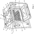
FIG. 1 is an environmental view of a freestanding range including a system for power management; -
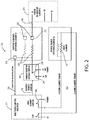
FIG. 2 is a schematic diagram of a system for power management; -
FIG. 3 is a flowchart of a method for control of an appliance implementing a system for power management; -
FIG. 4 is an environmental view of a cooktop including a system for power management; and -
FIG. 5 is a flowchart of a method for control of an appliance implementing a system for power management in accordance with the disclosure. - Referring to
FIGS. 1 and2 , a system for power management of a plurality of heating sources for an electric range is shown in accordance with the disclosure.Reference numeral 10 generally refers to an electric range incorporating apower management system 12. Theelectric range 10 includes acooktop element 14 and anoven element 16. Aswitch 18 is in electrical connection with thecooktop element 14 and configured to supply a first voltage or a second voltage to thecooktop element 14 from avoltage source 20. Thesystem 12 further comprises acontroller 22 in communication with theoven element 16, thecooktop element 14, and theswitch 18. Thecontroller 22 is configured to position theswitch 18 in afirst state 24 and asecond state 26. In thefirst state 24, thecontroller 12 controls theswitch 18 to supply the first voltage to thecooktop element 14 in response to an off-state of theoven element 16. In thesecond state 26, thecontroller 12 controls theswitch 18 to supply the second voltage to thecooktop element 14 in response to an on-state of theoven element 16. - The
system 12 provides numerous benefits including limiting the peak power usage of theelectric range 10 while maintaining a peak performance of the plurality ofcooktop elements 50 or the at least oneoven element 16 when operated individually. Though in this example, thesystem 12 is implemented in therange 10, thesystem 12 may similarly be implemented to selectively supply the first voltage or the second voltage to a first heating element in response to a state of operation (e.g. active, inactive) of a second heating element. The system may be implemented in various systems that include at least a first and a second heating element. - In reference to the implementation generally illustrated in
FIG. 1 , theelectric range 10 is shown including acooktop 42 and anoven 44. Theoven 44 comprises adoor 46 operably coupled to therange 10 and at least oneoven element 16 disposed in anoven cavity 48. Thecooktop 42 comprises a plurality ofcooktop elements 50 including thecooktop element 14. The plurality ofcooktop elements 50 are disposed on acooktop surface 52. Thepower management system 12 is operable to supply either a first voltage or a second voltage to the at least onecooktop element 14 of the plurality ofcooktop elements 50 in response to the operational state of the at least oneoven element 16. The elements (e.g. cooktop elements, oven elements) refer to heating elements that may be implemented in various home appliances. Each of the heating elements may correspond to a resistive heating element, inductive heating element, or any other form of heating element configured to operate from a voltage supply. Theelectric range 10 further comprises auser interface 54 including a plurality of control inputs 56 (e.g. oven controls, timer controls, clock controls, etc.), adisplay 58, and a plurality ofcooktop element controls 60. Theelectric range 10 is shown in an illustrative environment including acountertop 62 andcabinets 64. Thesystem 12 is configured to control a power supplied to at least one cooktop element from a voltage source in response to the activation of the at least oneoven element 16. In some implementations, thesystem 12 is configured to advantageously control a voltage supplied to thecooktop element 14 to supply a first voltage to thecooktop element 14 in response to theoven element 16 being in an inactive state. Thesystem 12 is further configured to supply a second voltage to thecooktop element 14 in response to theoven element 16 being in an active state. - Referring now to
FIGS. 1 and2 , thesystem 12 is incorporated in theelectric range 10 and in communication with the plurality ofcontrol inputs 56. Thesystem 12 provides various benefits including managing a power usage of thecooktop elements 50 when at least onecooktop element 14 is active in combination with the at least oneoven element 16 during a temporal period. Thesystem 12 is operable to limit the peak power usage of therange 10 by supplying a lower voltage to at least one of thecooktop elements 50 in response to theoven element 16 being active. By reducing the voltage supplied to the plurality ofcooktop elements 50, thesystem 12 is operable to reduce the peak power usage of therange 10 while maintaining the voltage supplied to theoven element 16. - Heating elements as referred to herein may refer to any electrically resistive element or device that may draw power in response to being activated. Activation as referred to herein refers to an on-state and any condition or state in which an electrical device, circuit, or element draws power.
- Referring now to
FIG. 2 , thepower management system 12 comprises acontroller 22 in communication with the at least onecooktop element 14 and the at least oneoven element 16. Thecontroller 22 is operable to detect or control an active or inactive state of thecooktop element 14 and theoven element 16. In some implementations, the at least onecooktop element 14 may comprise a plurality ofcooktop elements 50. Thecooktop elements 50 are supplied power from avoltage source 20 comprising a first line L1, a second line L2, and a neutral line N. Thevoltage source 20 may comprise a 3 or 4line 240V supply line at 60 Hz as typified in wiring standards in the United States. In such implementations, the fourth line may comprise a grounded connection. - Though the
voltage source 20 is referred to as a 240V supply line with a frequency of 60 Hz, the voltage source may vary based on a particular voltage supplied in an environment in which thesystem 12 is implemented. Thesystem 12 may be configured to operate with any voltage standard, for example 230V at 50 Hz, 220V at 50 Hz, etc. Additionally, thesystem 12 may be configured to operate at different voltages including 480V at 60 Hz, 460V at 50 Hz, 440V at 50 Hz, etc. It shall be understood to those skilled in the art that the various implementations of thesystem 12, some of which are described herein, may be configured to utilize any voltage source including any alternating current (AC) voltage source. - One of the first line L1 or the second line L2 may supply power to the
cooktop element 14 at afirst connection 66. A connection from the first line L1 to the second line L2 may provide the first voltage. Similarly a connection from either of the first line L1 or the second line L2 to the neutral line N may provide the second voltage. As shown, the first line L1 is in electrical communication with thecooktop element 14 via afirst cooktop control 72 of the cooktop element controls 60. Anindicator 74 is in communication with thecontroller 22 via a cooktop state indication input 76. Theindicator 74 is operable to detect and communicate a signal to thecontroller 22 in response to a control state of thecooktop element 14. - The
indicator 74, and other indicators introduced herein, may comprise any device or circuit operable to supply a signal to thecontroller 22 in response to power being supplied to a heating element. Upon activation of thecooktop element 14, theindicator 74 communicates a signal to thecontroller 22. In response to the signal, thecontroller 22 is configured to determine if thecooktop element 14 is active. In response to thecooktop element 14 being active, thecontroller 22 is configured to activate a power management control for thecooktop element 14. Theindicator 74 communicates the control state of thecooktop element 14 to limit unnecessary changes in theswitch 18 in response to theoven element 16 being active when thecooktop element 14 is inactive. In some implementations, thecontroller 22 may function without theindicator 74 and change from thefirst state 24 to thesecond state 26 any time that theoven element 16 is active. However, this configuration may cause unnecessary wear on theswitch 18. - The
switch 18 may comprise any electrical switching device, for example a relay, a 2-way relay, or a plurality of relays, in electrical communication with thecooktop element 14. Theswitch 18 is further in communication with thecontroller 22 via apower control output 78 which is configured to selectively activate thefirst state 24 and thesecond state 26 of theswitch 18. In thefirst state 24, the switch is in electrical communication with a second line L2 allowing current to flow from the first line L1 through thefirst cooktop control 72 and thecooktop element 14 to supply a first voltage to thecooktop element 14. As discussed herein, the first voltage may be 240V at 60 Hz. Thecontroller 22 is configured to maintain theswitch 18 in thefirst state 24 in response to theoven element 16 being inactive. - The
controller 22 is further configured to activate and control theoven element 16 in response to one or more inputs by a user into the plurality ofcontrol inputs 56 as shown inFIG. 1 . Similar to most modern ovens, thecontroller 22 may be operable to activate theoven element 16 via anoven element control 80, for example a relay or switch. Theoven element control 80 is configured to supply power to theoven element 16 from the first line L1 and through the second line L2 to form anoven element circuit 82. Theoven element circuit 82 may further comprise a double line-break DLB relay that serves as a safety device that is operable to disconnect/short theoven element circuit 82 in response to a fault condition. The fault condition may be detected by thecontroller 22 in response to an overheating condition or any other safety hazard detected by thecontroller 22. - In some implementations, the
controller 22 is operable to activate theoven element 16 via theoven element control 80. In some implementations, thecontroller 22 may be in communication with an indicator configured to communicate the operating state of anoven element 16. In either of these implementations, thecontroller 22 is configured to change the state of theswitch 18 from thefirst state 24 to thesecond state 26 through thepower control output 78 in response to theoven element 16 being configured in an active state and the cooktop state indication input 76 communicating that thecooktop element 14 is also in an active state. In thesecond state 26, theswitch 18 is in electrical communication with the neutral line N and is configured to supply the second voltage (e.g. 120v) from the first line L1, through thecooktop element 14, and through the neutral line N to complete the circuit in thesecond state 26. - In operation, the
controller 22 is operable to identify a control state or operating state of the plurality ofcooktop elements 50 and theoven element 16. During operation of one or more of thecooktop elements 50 during periods when theoven element 16 is inactive or off, thecontroller 22 maintains theswitch 18 in thefirst state 24 supplying the first voltage to thecooktop elements 50. During operation of theoven element 16 while thecooktop elements 50 are inactive or off, thecontroller 22 is also configured to maintain theswitch 18 in thefirst state 24. During operation of thecooktop elements 50 while theoven element 16 is active, the controller is configured to change the position of theswitch 18 to thesecond state 26 via thepower control output 78. In this way, the power usage of thesystem 12 is limited by supplying the second voltage (the lower voltage) to thecooktop elements 50 during active operation of both thecooktop elements 50 and theoven element 16. - As described above, the
system 12 is operable to limit a peak power consumption of the plurality ofcooktop elements 50 and at least oneoven element 16. The benefits of the unique configurations and controls, such as thecontroller 22, provide for maintaining high-performance from a first heating element (e.g. the cooktop element 14) and a second heating element (e.g. the oven element 16) during individual operation of either the first heating element or the second heating element. By supplying a first voltage to the first heating element in a first state and a second voltage to the first heating element in a second state, the controller of a power management system is operable to provide peak performance to the first heating element in response to the second heating element being inactive. This novel approach to controlling the power supplied to at least one heating element of a plurality of heating elements provides for benefits including limiting the peak power consumption of the plurality of heating elements while allowing at least one heating element to be selectively operated at a second voltage. Limiting the peak power consumption of the plurality of heating elements is particularly important to control the power required to operate the plurality heating elements in situations where a power supply may be limited or restricted. - Referring to
FIG. 3 , amethod 100 for operating thecooktop element 14 and theoven element 16 is shown. When activated, thecontroller 22 monitors theheating elements 50 including thecooktop element 14 and the oven element 16 (102). Thecontroller 22 monitors and/or controls the operating state of theoven element 16 to determine if theoven element 16 is active (104). If thecontroller 22 identifies that theoven element 16 is not active, thecontroller 22 is configured to control the position theswitch 18 to activate thefirst state 24. With theswitch 18 is positioned in thefirst state 24 thecooktop element 14 is in electrical connection with the second line L2 to supply the first voltage (e.g. 240V) to the cooktop element 14 (106). Followingstep 106, thecontroller 22 is configured to continue monitoring the heating elements by returning to step 102. - If the
controller 22 identifies that the oven element is active instep 104, the controller is further configured to determine if thecooktop element 14 is active (108). If thecooktop element 14 is active, thecontroller 22 is configured to control the position of theswitch 18 to activate thesecond state 26 by changing the connection of theswitch 18 from the second line L2 to the neutral line N (110). In thesecond state 26, thecooktop element 14 is in electrical connection with the neutral line to supply the second voltage (e.g. 120V) to thecooktop element 14. If thecooktop element 14 is inactive, thecontroller 22 is configured to maintain thefirst state 24 of the switch 18 (112). Thefirst state 24 of the switch may comprise an initial state or a resting state of theswitch 18 during operation of thesystem 12. Following either ofsteps heating elements - In various implementations of the
system 12, thecontroller 22 may comprise at least one circuit or processor configured to monitor and control the various inputs, outputs, switches and/or relays to accomplish the steps listed herein. In some implementations, thecontroller 22 may further be configured to receive inputs corresponding to thecontrol inputs 56 to control various timing and temperature related processes to control theoven element 16 and/or the plurality ofcooktop elements 14. Such processes may include maintaining and controlling temperature, preheating, timed cooking, timers, alarms and other various cooking controls related to cooktops, ovens, freestanding ranges, and other home appliances. The at least one circuit or processor ofcontroller 22 may be configured as a logic controller that may further be in communication with a memory. The memory may be configured to store and provide access to one or more programmable operations that may be referenced by the at least one circuit or processor to implement the steps discussed herein, including themethod 150 discussed herein in reference toFIG. 5 . - Referring to
FIG. 4 , thesystem 12 is similarly implemented in acooktop 120 comprising a plurality ofheating elements 122. One or more of theheating elements 122 may include aprimary heating element 124 and at least onesecondary heating element 126. Each of theheating elements 122 may correspond to a resistive heating element, inductive element or any other form of heating element configured to operate from a voltage supply. Thecooktop 120 further includes a plurality of cooktop element controls 126 configured to control a power supplied to each of the plurality ofheating elements 122. - In this implementation, the
system 12 may be in communication with each of theheating elements 122 and configured to identify and distinguish whether each ofheating elements 122, including theprimary heating elements 124 and thesecondary elements 126, is in an active state. In order to detect or identify if each of theheating elements 122 is active or inactive, a controller (similar to the controller 22) may be in communication with a plurality of indicators operable to communicate a state of operation (active/inactive, ON/OFF) of each of theheating elements 122. In this configuration, the controller is configured to detect and distinguish if one or more of theheating elements 122 are active. In response to the detection of at least one heating element in an active state, the controller is configured to control a switch to supply a first or a second voltage to a first plurality ofheating elements 128 or a second ofheating elements 130. - In some implementations, the first plurality of
heating elements 128 are supplied a first voltage (e.g. 240V) from a voltage source in response to the second plurality ofheating elements 130 being in an inactive state. To supply the first voltage to the first plurality ofheating elements 128, the controller is configured to control a position of a switch to a first state. In the first state, power is supplied to the first plurality ofheating elements 128 from a first line of a voltage source to a second line of the voltage source to supply the first voltage to the first plurality of heating elements. The second plurality ofheating elements 130 may be supplied the first voltage during either of an active or inactive condition of the first plurality ofheating elements 128 detected by the controller. - The controller is configured to lower the voltage supplied to the first plurality of
cooktop elements 128 in response to at least one of thesecond cooktop elements 130 being detected in an active state. That is, if at least one of the first plurality ofheating elements 128 is detected by the controller in an active state and at least one of the second plurality ofheating elements 130 is detected in an active state, the controller is configured to control the position of the switch to a second state. In the second state the switch supplies the second voltage to the first plurality ofheating elements 128. In the second state, the switch is configured to supply power to the first plurality ofheating elements 128 from the first line of the voltage source to a neutral line of the voltage source. - The
cooktop 120 provides similar advantages to thefreestanding range 10 introduced in reference toFIG. 1 in that thecooktop 120 includes thesystem 12 to limit a peak power consumption of thecooktop 120. Further, as demonstrated in this example, thesystem 12 may be implemented to control a peak power consumption of a variety of devices and systems comprising a plurality of heating elements. Though in this example the first plurality ofheating elements 128 and the second plurality ofheating elements 130 each refer to a set of two heating elements, a controller implemented similar to thesystem 12 may be configured to control the power supplied to any heating element or a portion of a heating element. For example, the controller may be configured to supply theprimary heating element 124, the second voltage in response to a detection of at least one heating element of a plurality of heating elements being active. - The systems, controllers, and methods discussed herein may further provide for multiple switches, similar to the
switch 18, to be controlled by one or more controllers (e.g. the controller 22) to selectively supply a first voltage or a second voltage to one or more heating elements of any number of heating elements. Such systems may be implemented by identifying one or more indications of at least one heating element of a first plurality of heating elements in an active state. The controller may further be operable to detect at least one heating element of a second plurality of heating elements in an active state. In response to at least one of the second heating elements being active, the controller may control a first switch of a plurality of switches or relays to provide a first or second voltage to at least one of the first plurality of heating elements. Further, in response to an indication of one of the first and one of the second pluralities of heating elements being in an active state, the controller may be operable to control a second switch of the plurality of switches or relays to provide a first or second voltage to at least a third heating element. - By implementing a controller configured to detect at least one heating element in an active state of a first plurality of heating elements and a second plurality of heating elements, the systems and methods discussed herein provide for a flexible architecture that is operable to limit a peak power consumption of a wide variety of systems and devices comprising a plurality of heating elements. Additional benefits of the flexible architecture as described herein include limiting the peak power consumption of a system based on states of operation corresponding to at least a first and a second heating element. In response to each of the states of operation, a controller may be configured to selectively supply a first voltage or a second voltage to the first or second heating elements.
- Referring now to
FIGS. 4 and5 , amethod 154 for operating thecooktop 120 is shown. As discussed herein, a controller, similar tocontroller 22, is configured to monitor an operating state of the plurality of heating elements 122 (152). In operation, the controller determines if one of the second plurality ofheating elements 130 is active (154). If the controller identifies that the second plurality ofheating elements 130 is inactive, the controller is configured to control the position of a switch to activate or maintain a first state. In the first state, the first plurality ofheating elements 128 is in electrical connection with the first line L1 and the second line L2 to supply the first voltage (e.g. 240V) to the first plurality of heating elements 128 (156). Followingstep 156, the controller is configured to continue monitoring theheating elements 122 by returning to step 152. - If the controller identifies that at least one of the second plurality of
heating elements 130 is active, the controller is further configured to determine if at least one of the first plurality ofelements 128 is active (158). If at least one of the first plurality ofheating elements 128 is active, the controller is configured to control the position of the switch to activate the second state by changing the connection of the switch from the second line L2 to the neutral line N (160). In the second state, thefirst heating elements 128 are in electrical connection with the first line L1 and the neutral line N to supply the second voltage (e.g. 120V) to the first plurality ofheating elements 128. If the first plurality ofheating elements 128 is inactive, the controller is configured to maintain the first state of the switch (152). Following either ofsteps heating elements 122 by returning to step 152.
Claims (7)
- A system for power management (12) of a plurality of heating sources for an electric range (10), the system comprising:a cooktop heating element (14);an oven heating element (16);a switch (18) in electrical connection with the cooktop heating element (14) and configured to supply a first voltage or a second voltage to the cooktop heating element (14) from a voltage source (20),characterized in that the system comprises a controller (22) in communication with the oven heating element (16) and configured to control the at least one switch (18), the controller (22) being operable between:a first state (24), wherein the controller (22) controls the switch (18) to supply the first voltage to the cooktop heating element (14) in response to an off-state of the oven element (16); anda second state (26), wherein the controller (22) controls the switch (18) to supply the second voltage to the cooktop heating element (14) in response to an on-state of the oven heating element (16).
- The system according to claim 1, wherein the first voltage is greater than the second voltage.
- The system according to claims 1 or 2, wherein the controller (22) is further in communication with at least one indicator (74) of the oven heating element (16) to receive an indication of a state of the oven heating element (16).
- The system according to claims 1-3, wherein the voltage supply comprises a first line (L1), a second line (L2), and a neutral line (N), the first line (L1) being in electrical connection with the cooktop heating element (14).
- The system according to claims 1-4, wherein the controller (22) is further operable to supply the first voltage to the cooktop by controlling the switch (18) to connect to the second line (L2) in the first state (24).
- The system according to claims 1-5, wherein the controller (22) is further operable to supply the second voltage the cooktop heating element (14) by controlling the switch (18) to connect to the neutral line (N) in the second state (26).
- The system according to claims 1-6, wherein the first voltage is approximately 240v and the second voltage is approximately 120V.
Applications Claiming Priority (1)
| Application Number | Priority Date | Filing Date | Title |
|---|---|---|---|
| US14/255,007 US10024545B2 (en) | 2014-04-17 | 2014-04-17 | Power management for home appliances |
Publications (2)
| Publication Number | Publication Date |
|---|---|
| EP2934064A1 EP2934064A1 (en) | 2015-10-21 |
| EP2934064B1 true EP2934064B1 (en) | 2019-08-21 |
Family
ID=52875425
Family Applications (1)
| Application Number | Title | Priority Date | Filing Date |
|---|---|---|---|
| EP15159298.7A Active EP2934064B1 (en) | 2014-04-17 | 2015-03-16 | Power management for home appliances |
Country Status (2)
| Country | Link |
|---|---|
| US (1) | US10024545B2 (en) |
| EP (1) | EP2934064B1 (en) |
Families Citing this family (5)
| Publication number | Priority date | Publication date | Assignee | Title |
|---|---|---|---|---|
| KR20160010093A (en) * | 2014-07-18 | 2016-01-27 | 삼성전자주식회사 | Home appliance, a controller for controlling the home appliance, system for controlling a home appliance using the controller, method of controlling the home appliance and non-transitory computer readable storage medium |
| WO2018116063A1 (en) * | 2016-12-23 | 2018-06-28 | BSH Hausgeräte GmbH | Cooking appliance apparatus, and method for operating a cooking appliance apparatus |
| US11041622B2 (en) * | 2019-01-04 | 2021-06-22 | Haier Us Appliance Solutions, Inc. | Gas cooktop with power management |
| DE102019106072B4 (en) * | 2019-03-11 | 2021-01-14 | TQS - Technical Quartz Solutions GmbH | Method for operating an infrared heater and device with an infrared heater |
| EP4290137A1 (en) * | 2022-06-07 | 2023-12-13 | SMEG S.p.A. | Appliance system and method for managing an appliance system |
Family Cites Families (22)
| Publication number | Priority date | Publication date | Assignee | Title |
|---|---|---|---|---|
| US2263420A (en) | 1939-07-17 | 1941-11-18 | Swartzbaugh Mfg Company | Circuit for electric ranges |
| DE2605533B2 (en) | 1976-02-12 | 1980-03-27 | Licentia Patent-Verwaltungs-Gmbh, 6000 Frankfurt | Electronic control device for electric cookers |
| FR2466047A1 (en) | 1979-09-21 | 1981-03-27 | Humbert Daniel | Electricity consumer power loading regulator - provides priority circuit power without cutting other loads |
| US4663067A (en) * | 1985-10-31 | 1987-05-05 | Earth Protection Systems, Inc. | Transient soil erosion and evaporation palliative composition and method |
| US5280157A (en) * | 1992-01-31 | 1994-01-18 | General Electric Company | Power switching arrangement for cooking oven |
| IT1255162B (en) | 1992-06-23 | 1995-10-20 | Smeg Spa | HOB WITH ELECTRONICALLY CONTROLLED MULTIPLE ELECTRIC PLATES |
| IL109402A0 (en) | 1994-04-22 | 1994-07-31 | Yahav Shimon | Electrical cooking apparatus |
| US5932128A (en) * | 1997-02-26 | 1999-08-03 | White Consolidated Industries, Inc. | Switching control system for heating panel with leakage current cancellation |
| US6157008A (en) | 1999-07-08 | 2000-12-05 | Maytag Corporation | Power distribution system for an appliance |
| KR100653056B1 (en) | 2001-03-09 | 2006-12-01 | 삼성전자주식회사 | microwave oven and method of controlling for power saving mode thereof |
| US6497276B2 (en) | 2001-03-31 | 2002-12-24 | Ron D. Clark | Combined refrigerator-oven apparatus |
| DE10121534A1 (en) * | 2001-05-03 | 2002-11-07 | Bsh Bosch Siemens Hausgeraete | display device |
| ITMI20011253A1 (en) | 2001-06-14 | 2002-12-14 | Whirlpool Co | POWER MANAGEMENT SYSTEM IN ELECTRIC COOKING APPLIANCES |
| KR20030018548A (en) | 2001-08-30 | 2003-03-06 | 주식회사 엘지이아이 | Power control device for over the range |
| US7420142B2 (en) * | 2002-07-26 | 2008-09-02 | Illinois Tool Works, Inc | Power control module for electrical appliances |
| ES2300168B1 (en) | 2005-10-27 | 2009-05-08 | Bsh Electrodomesticos España, S.A. | KITCHEN HOB AND PROCEDURE FOR THE OPERATION OF A KITCHEN HOB. |
| US7368686B2 (en) * | 2006-09-06 | 2008-05-06 | General Electric Company | Apparatus and methods for operating an electric appliance |
| US20090167085A1 (en) | 2007-12-28 | 2009-07-02 | Julia Fonseca | Voltage Detection System for a Range |
| US8102080B2 (en) * | 2007-12-28 | 2012-01-24 | General Electric Company | Control system for an appliance |
| US8541719B2 (en) * | 2008-09-15 | 2013-09-24 | General Electric Company | System for reduced peak power consumption by a cooking appliance |
| US20100200565A1 (en) * | 2009-02-06 | 2010-08-12 | Leung Tony W | Control system for electric heating elements |
| US8344292B2 (en) * | 2009-12-21 | 2013-01-01 | Whirlpool Corporation | Rotary switch with improved simmer performance |
-
2014
- 2014-04-17 US US14/255,007 patent/US10024545B2/en active Active
-
2015
- 2015-03-16 EP EP15159298.7A patent/EP2934064B1/en active Active
Non-Patent Citations (1)
| Title |
|---|
| None * |
Also Published As
| Publication number | Publication date |
|---|---|
| EP2934064A1 (en) | 2015-10-21 |
| US10024545B2 (en) | 2018-07-17 |
| US20150300651A1 (en) | 2015-10-22 |
Similar Documents
| Publication | Publication Date | Title |
|---|---|---|
| EP2934064B1 (en) | Power management for home appliances | |
| AU2015292881B2 (en) | Heating element control circuit | |
| US7045748B2 (en) | Cooking appliance lockout | |
| US20080083729A1 (en) | Apparatus and methods for operating an electric appliance | |
| US10237925B2 (en) | Cooking appliance | |
| CN204438245U (en) | Electricity cooking pot and control circuit thereof | |
| EP3038431B1 (en) | Circuit for driving cooker, system for driving cooker, cooker, and method for driving cooker | |
| EP0576408B1 (en) | Cooking hob provided with electronically controlled multiple electric plates | |
| KR20160133189A (en) | Cooking appliance and Methof for controlling it | |
| EP4033153A1 (en) | Domestic appliance with stand-by function | |
| CN1888568B (en) | Safety device for microwave oven | |
| KR100667210B1 (en) | Microwave oven and control method thereof | |
| CN114080072B (en) | Relay state detection method, device and equipment of electromagnetic heating appliance | |
| CN203812033U (en) | Multi-direction sensing power supply control device | |
| CN105992400B (en) | Heating control device, heating control method and cooking utensil | |
| KR102040390B1 (en) | Temperature controlling apparatus for inductive heating device | |
| EP3575693A1 (en) | Electric oven and method of operation of such oven | |
| JP2022044872A (en) | Induction heating cooker | |
| EP2432295B1 (en) | Method and system for controlling a resistive load | |
| CA2579549C (en) | Apparatus and methods for operating an electric appliance | |
| EP2659588B1 (en) | A control unit used in household appliances | |
| KR20000042583A (en) | Electric power saving circuit | |
| CN108167886A (en) | A kind of electromagnetic heater of changeable heating cavity | |
| KR19980028996U (en) | Non-operating display device according to the operation of the safety device of the microwave oven | |
| KR20010048742A (en) | Method and apparatus for driving heater of micro wave oven |
Legal Events
| Date | Code | Title | Description |
|---|---|---|---|
| PUAI | Public reference made under article 153(3) epc to a published international application that has entered the european phase |
Free format text: ORIGINAL CODE: 0009012 |
|
| AK | Designated contracting states |
Kind code of ref document: A1 Designated state(s): AL AT BE BG CH CY CZ DE DK EE ES FI FR GB GR HR HU IE IS IT LI LT LU LV MC MK MT NL NO PL PT RO RS SE SI SK SM TR |
|
| AX | Request for extension of the european patent |
Extension state: BA ME |
|
| 17P | Request for examination filed |
Effective date: 20160420 |
|
| RBV | Designated contracting states (corrected) |
Designated state(s): AL AT BE BG CH CY CZ DE DK EE ES FI FR GB GR HR HU IE IS IT LI LT LU LV MC MK MT NL NO PL PT RO RS SE SI SK SM TR |
|
| GRAP | Despatch of communication of intention to grant a patent |
Free format text: ORIGINAL CODE: EPIDOSNIGR1 |
|
| STAA | Information on the status of an ep patent application or granted ep patent |
Free format text: STATUS: GRANT OF PATENT IS INTENDED |
|
| INTG | Intention to grant announced |
Effective date: 20190528 |
|
| GRAS | Grant fee paid |
Free format text: ORIGINAL CODE: EPIDOSNIGR3 |
|
| GRAA | (expected) grant |
Free format text: ORIGINAL CODE: 0009210 |
|
| STAA | Information on the status of an ep patent application or granted ep patent |
Free format text: STATUS: THE PATENT HAS BEEN GRANTED |
|
| AK | Designated contracting states |
Kind code of ref document: B1 Designated state(s): AL AT BE BG CH CY CZ DE DK EE ES FI FR GB GR HR HU IE IS IT LI LT LU LV MC MK MT NL NO PL PT RO RS SE SI SK SM TR |
|
| REG | Reference to a national code |
Ref country code: GB Ref legal event code: FG4D |
|
| REG | Reference to a national code |
Ref country code: CH Ref legal event code: EP |
|
| REG | Reference to a national code |
Ref country code: DE Ref legal event code: R096 Ref document number: 602015036135 Country of ref document: DE |
|
| REG | Reference to a national code |
Ref country code: AT Ref legal event code: REF Ref document number: 1171219 Country of ref document: AT Kind code of ref document: T Effective date: 20190915 |
|
| REG | Reference to a national code |
Ref country code: IE Ref legal event code: FG4D |
|
| REG | Reference to a national code |
Ref country code: LT Ref legal event code: MG4D |
|
| REG | Reference to a national code |
Ref country code: NL Ref legal event code: MP Effective date: 20190821 |
|
| PG25 | Lapsed in a contracting state [announced via postgrant information from national office to epo] |
Ref country code: PT Free format text: LAPSE BECAUSE OF FAILURE TO SUBMIT A TRANSLATION OF THE DESCRIPTION OR TO PAY THE FEE WITHIN THE PRESCRIBED TIME-LIMIT Effective date: 20191223 Ref country code: NO Free format text: LAPSE BECAUSE OF FAILURE TO SUBMIT A TRANSLATION OF THE DESCRIPTION OR TO PAY THE FEE WITHIN THE PRESCRIBED TIME-LIMIT Effective date: 20191121 Ref country code: HR Free format text: LAPSE BECAUSE OF FAILURE TO SUBMIT A TRANSLATION OF THE DESCRIPTION OR TO PAY THE FEE WITHIN THE PRESCRIBED TIME-LIMIT Effective date: 20190821 Ref country code: SE Free format text: LAPSE BECAUSE OF FAILURE TO SUBMIT A TRANSLATION OF THE DESCRIPTION OR TO PAY THE FEE WITHIN THE PRESCRIBED TIME-LIMIT Effective date: 20190821 Ref country code: FI Free format text: LAPSE BECAUSE OF FAILURE TO SUBMIT A TRANSLATION OF THE DESCRIPTION OR TO PAY THE FEE WITHIN THE PRESCRIBED TIME-LIMIT Effective date: 20190821 Ref country code: LT Free format text: LAPSE BECAUSE OF FAILURE TO SUBMIT A TRANSLATION OF THE DESCRIPTION OR TO PAY THE FEE WITHIN THE PRESCRIBED TIME-LIMIT Effective date: 20190821 Ref country code: NL Free format text: LAPSE BECAUSE OF FAILURE TO SUBMIT A TRANSLATION OF THE DESCRIPTION OR TO PAY THE FEE WITHIN THE PRESCRIBED TIME-LIMIT Effective date: 20190821 Ref country code: BG Free format text: LAPSE BECAUSE OF FAILURE TO SUBMIT A TRANSLATION OF THE DESCRIPTION OR TO PAY THE FEE WITHIN THE PRESCRIBED TIME-LIMIT Effective date: 20191121 |
|
| PG25 | Lapsed in a contracting state [announced via postgrant information from national office to epo] |
Ref country code: ES Free format text: LAPSE BECAUSE OF FAILURE TO SUBMIT A TRANSLATION OF THE DESCRIPTION OR TO PAY THE FEE WITHIN THE PRESCRIBED TIME-LIMIT Effective date: 20190821 Ref country code: AL Free format text: LAPSE BECAUSE OF FAILURE TO SUBMIT A TRANSLATION OF THE DESCRIPTION OR TO PAY THE FEE WITHIN THE PRESCRIBED TIME-LIMIT Effective date: 20190821 Ref country code: LV Free format text: LAPSE BECAUSE OF FAILURE TO SUBMIT A TRANSLATION OF THE DESCRIPTION OR TO PAY THE FEE WITHIN THE PRESCRIBED TIME-LIMIT Effective date: 20190821 Ref country code: GR Free format text: LAPSE BECAUSE OF FAILURE TO SUBMIT A TRANSLATION OF THE DESCRIPTION OR TO PAY THE FEE WITHIN THE PRESCRIBED TIME-LIMIT Effective date: 20191122 Ref country code: IS Free format text: LAPSE BECAUSE OF FAILURE TO SUBMIT A TRANSLATION OF THE DESCRIPTION OR TO PAY THE FEE WITHIN THE PRESCRIBED TIME-LIMIT Effective date: 20191221 Ref country code: RS Free format text: LAPSE BECAUSE OF FAILURE TO SUBMIT A TRANSLATION OF THE DESCRIPTION OR TO PAY THE FEE WITHIN THE PRESCRIBED TIME-LIMIT Effective date: 20190821 |
|
| REG | Reference to a national code |
Ref country code: AT Ref legal event code: MK05 Ref document number: 1171219 Country of ref document: AT Kind code of ref document: T Effective date: 20190821 |
|
| PG25 | Lapsed in a contracting state [announced via postgrant information from national office to epo] |
Ref country code: TR Free format text: LAPSE BECAUSE OF FAILURE TO SUBMIT A TRANSLATION OF THE DESCRIPTION OR TO PAY THE FEE WITHIN THE PRESCRIBED TIME-LIMIT Effective date: 20190821 |
|
| PG25 | Lapsed in a contracting state [announced via postgrant information from national office to epo] |
Ref country code: RO Free format text: LAPSE BECAUSE OF FAILURE TO SUBMIT A TRANSLATION OF THE DESCRIPTION OR TO PAY THE FEE WITHIN THE PRESCRIBED TIME-LIMIT Effective date: 20190821 Ref country code: EE Free format text: LAPSE BECAUSE OF FAILURE TO SUBMIT A TRANSLATION OF THE DESCRIPTION OR TO PAY THE FEE WITHIN THE PRESCRIBED TIME-LIMIT Effective date: 20190821 Ref country code: PL Free format text: LAPSE BECAUSE OF FAILURE TO SUBMIT A TRANSLATION OF THE DESCRIPTION OR TO PAY THE FEE WITHIN THE PRESCRIBED TIME-LIMIT Effective date: 20190821 Ref country code: AT Free format text: LAPSE BECAUSE OF FAILURE TO SUBMIT A TRANSLATION OF THE DESCRIPTION OR TO PAY THE FEE WITHIN THE PRESCRIBED TIME-LIMIT Effective date: 20190821 Ref country code: DK Free format text: LAPSE BECAUSE OF FAILURE TO SUBMIT A TRANSLATION OF THE DESCRIPTION OR TO PAY THE FEE WITHIN THE PRESCRIBED TIME-LIMIT Effective date: 20190821 |
|
| PG25 | Lapsed in a contracting state [announced via postgrant information from national office to epo] |
Ref country code: IS Free format text: LAPSE BECAUSE OF FAILURE TO SUBMIT A TRANSLATION OF THE DESCRIPTION OR TO PAY THE FEE WITHIN THE PRESCRIBED TIME-LIMIT Effective date: 20200224 Ref country code: CZ Free format text: LAPSE BECAUSE OF FAILURE TO SUBMIT A TRANSLATION OF THE DESCRIPTION OR TO PAY THE FEE WITHIN THE PRESCRIBED TIME-LIMIT Effective date: 20190821 Ref country code: SM Free format text: LAPSE BECAUSE OF FAILURE TO SUBMIT A TRANSLATION OF THE DESCRIPTION OR TO PAY THE FEE WITHIN THE PRESCRIBED TIME-LIMIT Effective date: 20190821 Ref country code: SK Free format text: LAPSE BECAUSE OF FAILURE TO SUBMIT A TRANSLATION OF THE DESCRIPTION OR TO PAY THE FEE WITHIN THE PRESCRIBED TIME-LIMIT Effective date: 20190821 |
|
| REG | Reference to a national code |
Ref country code: DE Ref legal event code: R097 Ref document number: 602015036135 Country of ref document: DE |
|
| PLBE | No opposition filed within time limit |
Free format text: ORIGINAL CODE: 0009261 |
|
| STAA | Information on the status of an ep patent application or granted ep patent |
Free format text: STATUS: NO OPPOSITION FILED WITHIN TIME LIMIT |
|
| PG2D | Information on lapse in contracting state deleted |
Ref country code: IS |
|
| 26N | No opposition filed |
Effective date: 20200603 |
|
| PG25 | Lapsed in a contracting state [announced via postgrant information from national office to epo] |
Ref country code: SI Free format text: LAPSE BECAUSE OF FAILURE TO SUBMIT A TRANSLATION OF THE DESCRIPTION OR TO PAY THE FEE WITHIN THE PRESCRIBED TIME-LIMIT Effective date: 20190821 |
|
| PG25 | Lapsed in a contracting state [announced via postgrant information from national office to epo] |
Ref country code: MC Free format text: LAPSE BECAUSE OF FAILURE TO SUBMIT A TRANSLATION OF THE DESCRIPTION OR TO PAY THE FEE WITHIN THE PRESCRIBED TIME-LIMIT Effective date: 20190821 |
|
| REG | Reference to a national code |
Ref country code: CH Ref legal event code: PL |
|
| REG | Reference to a national code |
Ref country code: BE Ref legal event code: MM Effective date: 20200331 |
|
| PG25 | Lapsed in a contracting state [announced via postgrant information from national office to epo] |
Ref country code: LU Free format text: LAPSE BECAUSE OF NON-PAYMENT OF DUE FEES Effective date: 20200316 |
|
| PG25 | Lapsed in a contracting state [announced via postgrant information from national office to epo] |
Ref country code: IE Free format text: LAPSE BECAUSE OF NON-PAYMENT OF DUE FEES Effective date: 20200316 Ref country code: CH Free format text: LAPSE BECAUSE OF NON-PAYMENT OF DUE FEES Effective date: 20200331 Ref country code: LI Free format text: LAPSE BECAUSE OF NON-PAYMENT OF DUE FEES Effective date: 20200331 |
|
| PG25 | Lapsed in a contracting state [announced via postgrant information from national office to epo] |
Ref country code: BE Free format text: LAPSE BECAUSE OF NON-PAYMENT OF DUE FEES Effective date: 20200331 |
|
| PG25 | Lapsed in a contracting state [announced via postgrant information from national office to epo] |
Ref country code: MT Free format text: LAPSE BECAUSE OF FAILURE TO SUBMIT A TRANSLATION OF THE DESCRIPTION OR TO PAY THE FEE WITHIN THE PRESCRIBED TIME-LIMIT Effective date: 20190821 Ref country code: CY Free format text: LAPSE BECAUSE OF FAILURE TO SUBMIT A TRANSLATION OF THE DESCRIPTION OR TO PAY THE FEE WITHIN THE PRESCRIBED TIME-LIMIT Effective date: 20190821 |
|
| PG25 | Lapsed in a contracting state [announced via postgrant information from national office to epo] |
Ref country code: MK Free format text: LAPSE BECAUSE OF FAILURE TO SUBMIT A TRANSLATION OF THE DESCRIPTION OR TO PAY THE FEE WITHIN THE PRESCRIBED TIME-LIMIT Effective date: 20190821 |
|
| PGFP | Annual fee paid to national office [announced via postgrant information from national office to epo] |
Ref country code: FR Payment date: 20230110 Year of fee payment: 9 |
|
| PGFP | Annual fee paid to national office [announced via postgrant information from national office to epo] |
Ref country code: IT Payment date: 20230213 Year of fee payment: 9 Ref country code: GB Payment date: 20230126 Year of fee payment: 9 Ref country code: DE Payment date: 20230117 Year of fee payment: 9 |
|
| P01 | Opt-out of the competence of the unified patent court (upc) registered |
Effective date: 20230522 |