EP3038081A1 - Method for adjusting liquid crystal display and apparatus thereof - Google Patents
Method for adjusting liquid crystal display and apparatus thereof Download PDFInfo
- Publication number
- EP3038081A1 EP3038081A1 EP15202344.6A EP15202344A EP3038081A1 EP 3038081 A1 EP3038081 A1 EP 3038081A1 EP 15202344 A EP15202344 A EP 15202344A EP 3038081 A1 EP3038081 A1 EP 3038081A1
- Authority
- EP
- European Patent Office
- Prior art keywords
- load voltage
- liquid crystal
- crystal display
- transmittance
- voltage
- Prior art date
- Legal status (The legal status is an assumption and is not a legal conclusion. Google has not performed a legal analysis and makes no representation as to the accuracy of the status listed.)
- Ceased
Links
Images


Classifications
-
- G—PHYSICS
- G09—EDUCATION; CRYPTOGRAPHY; DISPLAY; ADVERTISING; SEALS
- G09G—ARRANGEMENTS OR CIRCUITS FOR CONTROL OF INDICATING DEVICES USING STATIC MEANS TO PRESENT VARIABLE INFORMATION
- G09G3/00—Control arrangements or circuits, of interest only in connection with visual indicators other than cathode-ray tubes
- G09G3/20—Control arrangements or circuits, of interest only in connection with visual indicators other than cathode-ray tubes for presentation of an assembly of a number of characters, e.g. a page, by composing the assembly by combination of individual elements arranged in a matrix no fixed position being assigned to or needed to be assigned to the individual characters or partial characters
- G09G3/34—Control arrangements or circuits, of interest only in connection with visual indicators other than cathode-ray tubes for presentation of an assembly of a number of characters, e.g. a page, by composing the assembly by combination of individual elements arranged in a matrix no fixed position being assigned to or needed to be assigned to the individual characters or partial characters by control of light from an independent source
- G09G3/36—Control arrangements or circuits, of interest only in connection with visual indicators other than cathode-ray tubes for presentation of an assembly of a number of characters, e.g. a page, by composing the assembly by combination of individual elements arranged in a matrix no fixed position being assigned to or needed to be assigned to the individual characters or partial characters by control of light from an independent source using liquid crystals
- G09G3/3611—Control of matrices with row and column drivers
- G09G3/3648—Control of matrices with row and column drivers using an active matrix
-
- H—ELECTRICITY
- H01—ELECTRIC ELEMENTS
- H01H—ELECTRIC SWITCHES; RELAYS; SELECTORS; EMERGENCY PROTECTIVE DEVICES
- H01H13/00—Switches having rectilinearly-movable operating part or parts adapted for pushing or pulling in one direction only, e.g. push-button switch
- H01H13/70—Switches having rectilinearly-movable operating part or parts adapted for pushing or pulling in one direction only, e.g. push-button switch having a plurality of operating members associated with different sets of contacts, e.g. keyboard
- H01H13/83—Switches having rectilinearly-movable operating part or parts adapted for pushing or pulling in one direction only, e.g. push-button switch having a plurality of operating members associated with different sets of contacts, e.g. keyboard characterised by legends, e.g. Braille, liquid crystal displays, light emitting or optical elements
-
- G—PHYSICS
- G09—EDUCATION; CRYPTOGRAPHY; DISPLAY; ADVERTISING; SEALS
- G09G—ARRANGEMENTS OR CIRCUITS FOR CONTROL OF INDICATING DEVICES USING STATIC MEANS TO PRESENT VARIABLE INFORMATION
- G09G3/00—Control arrangements or circuits, of interest only in connection with visual indicators other than cathode-ray tubes
- G09G3/006—Electronic inspection or testing of displays and display drivers, e.g. of LED or LCD displays
-
- G—PHYSICS
- G09—EDUCATION; CRYPTOGRAPHY; DISPLAY; ADVERTISING; SEALS
- G09G—ARRANGEMENTS OR CIRCUITS FOR CONTROL OF INDICATING DEVICES USING STATIC MEANS TO PRESENT VARIABLE INFORMATION
- G09G3/00—Control arrangements or circuits, of interest only in connection with visual indicators other than cathode-ray tubes
- G09G3/20—Control arrangements or circuits, of interest only in connection with visual indicators other than cathode-ray tubes for presentation of an assembly of a number of characters, e.g. a page, by composing the assembly by combination of individual elements arranged in a matrix no fixed position being assigned to or needed to be assigned to the individual characters or partial characters
- G09G3/2003—Display of colours
-
- G—PHYSICS
- G09—EDUCATION; CRYPTOGRAPHY; DISPLAY; ADVERTISING; SEALS
- G09G—ARRANGEMENTS OR CIRCUITS FOR CONTROL OF INDICATING DEVICES USING STATIC MEANS TO PRESENT VARIABLE INFORMATION
- G09G3/00—Control arrangements or circuits, of interest only in connection with visual indicators other than cathode-ray tubes
- G09G3/20—Control arrangements or circuits, of interest only in connection with visual indicators other than cathode-ray tubes for presentation of an assembly of a number of characters, e.g. a page, by composing the assembly by combination of individual elements arranged in a matrix no fixed position being assigned to or needed to be assigned to the individual characters or partial characters
- G09G3/34—Control arrangements or circuits, of interest only in connection with visual indicators other than cathode-ray tubes for presentation of an assembly of a number of characters, e.g. a page, by composing the assembly by combination of individual elements arranged in a matrix no fixed position being assigned to or needed to be assigned to the individual characters or partial characters by control of light from an independent source
- G09G3/36—Control arrangements or circuits, of interest only in connection with visual indicators other than cathode-ray tubes for presentation of an assembly of a number of characters, e.g. a page, by composing the assembly by combination of individual elements arranged in a matrix no fixed position being assigned to or needed to be assigned to the individual characters or partial characters by control of light from an independent source using liquid crystals
- G09G3/3611—Control of matrices with row and column drivers
-
- G—PHYSICS
- G09—EDUCATION; CRYPTOGRAPHY; DISPLAY; ADVERTISING; SEALS
- G09G—ARRANGEMENTS OR CIRCUITS FOR CONTROL OF INDICATING DEVICES USING STATIC MEANS TO PRESENT VARIABLE INFORMATION
- G09G3/00—Control arrangements or circuits, of interest only in connection with visual indicators other than cathode-ray tubes
- G09G3/20—Control arrangements or circuits, of interest only in connection with visual indicators other than cathode-ray tubes for presentation of an assembly of a number of characters, e.g. a page, by composing the assembly by combination of individual elements arranged in a matrix no fixed position being assigned to or needed to be assigned to the individual characters or partial characters
- G09G3/34—Control arrangements or circuits, of interest only in connection with visual indicators other than cathode-ray tubes for presentation of an assembly of a number of characters, e.g. a page, by composing the assembly by combination of individual elements arranged in a matrix no fixed position being assigned to or needed to be assigned to the individual characters or partial characters by control of light from an independent source
- G09G3/36—Control arrangements or circuits, of interest only in connection with visual indicators other than cathode-ray tubes for presentation of an assembly of a number of characters, e.g. a page, by composing the assembly by combination of individual elements arranged in a matrix no fixed position being assigned to or needed to be assigned to the individual characters or partial characters by control of light from an independent source using liquid crystals
- G09G3/3611—Control of matrices with row and column drivers
- G09G3/3696—Generation of voltages supplied to electrode drivers
-
- G—PHYSICS
- G09—EDUCATION; CRYPTOGRAPHY; DISPLAY; ADVERTISING; SEALS
- G09G—ARRANGEMENTS OR CIRCUITS FOR CONTROL OF INDICATING DEVICES USING STATIC MEANS TO PRESENT VARIABLE INFORMATION
- G09G2320/00—Control of display operating conditions
- G09G2320/02—Improving the quality of display appearance
- G09G2320/0242—Compensation of deficiencies in the appearance of colours
-
- G—PHYSICS
- G09—EDUCATION; CRYPTOGRAPHY; DISPLAY; ADVERTISING; SEALS
- G09G—ARRANGEMENTS OR CIRCUITS FOR CONTROL OF INDICATING DEVICES USING STATIC MEANS TO PRESENT VARIABLE INFORMATION
- G09G2320/00—Control of display operating conditions
- G09G2320/02—Improving the quality of display appearance
- G09G2320/0271—Adjustment of the gradation levels within the range of the gradation scale, e.g. by redistribution or clipping
- G09G2320/0276—Adjustment of the gradation levels within the range of the gradation scale, e.g. by redistribution or clipping for the purpose of adaptation to the characteristics of a display device, i.e. gamma correction
-
- G—PHYSICS
- G09—EDUCATION; CRYPTOGRAPHY; DISPLAY; ADVERTISING; SEALS
- G09G—ARRANGEMENTS OR CIRCUITS FOR CONTROL OF INDICATING DEVICES USING STATIC MEANS TO PRESENT VARIABLE INFORMATION
- G09G2320/00—Control of display operating conditions
- G09G2320/06—Adjustment of display parameters
- G09G2320/0666—Adjustment of display parameters for control of colour parameters, e.g. colour temperature
-
- G—PHYSICS
- G09—EDUCATION; CRYPTOGRAPHY; DISPLAY; ADVERTISING; SEALS
- G09G—ARRANGEMENTS OR CIRCUITS FOR CONTROL OF INDICATING DEVICES USING STATIC MEANS TO PRESENT VARIABLE INFORMATION
- G09G2320/00—Control of display operating conditions
- G09G2320/06—Adjustment of display parameters
- G09G2320/0673—Adjustment of display parameters for control of gamma adjustment, e.g. selecting another gamma curve
-
- G—PHYSICS
- G09—EDUCATION; CRYPTOGRAPHY; DISPLAY; ADVERTISING; SEALS
- G09G—ARRANGEMENTS OR CIRCUITS FOR CONTROL OF INDICATING DEVICES USING STATIC MEANS TO PRESENT VARIABLE INFORMATION
- G09G2320/00—Control of display operating conditions
- G09G2320/06—Adjustment of display parameters
- G09G2320/0693—Calibration of display systems
-
- G—PHYSICS
- G09—EDUCATION; CRYPTOGRAPHY; DISPLAY; ADVERTISING; SEALS
- G09G—ARRANGEMENTS OR CIRCUITS FOR CONTROL OF INDICATING DEVICES USING STATIC MEANS TO PRESENT VARIABLE INFORMATION
- G09G2320/00—Control of display operating conditions
- G09G2320/08—Arrangements within a display terminal for setting, manually or automatically, display parameters of the display terminal
-
- G—PHYSICS
- G09—EDUCATION; CRYPTOGRAPHY; DISPLAY; ADVERTISING; SEALS
- G09G—ARRANGEMENTS OR CIRCUITS FOR CONTROL OF INDICATING DEVICES USING STATIC MEANS TO PRESENT VARIABLE INFORMATION
- G09G2360/00—Aspects of the architecture of display systems
- G09G2360/14—Detecting light within display terminals, e.g. using a single or a plurality of photosensors
- G09G2360/145—Detecting light within display terminals, e.g. using a single or a plurality of photosensors the light originating from the display screen
-
- G—PHYSICS
- G09—EDUCATION; CRYPTOGRAPHY; DISPLAY; ADVERTISING; SEALS
- G09G—ARRANGEMENTS OR CIRCUITS FOR CONTROL OF INDICATING DEVICES USING STATIC MEANS TO PRESENT VARIABLE INFORMATION
- G09G2360/00—Aspects of the architecture of display systems
- G09G2360/16—Calculation or use of calculated indices related to luminance levels in display data
Definitions
- the present invention generally relates to a field of liquid crystal display technology, and more particularly to a method for adjusting a liquid crystal display and an apparatus thereof.
- a method of improving the perspective rate of the liquid crystal display includes: decreasing regions of a black matrix BM, increasing an antireflection film, using a negative liquid crystal and changing the configuration of pixel electrodes, which implies changes on the structure of the liquid crystal display.
- the embodiments of the present invention provide a method for adjusting a liquid crystal display and an apparatus thereof, so as to improve brightness of the liquid crystal display.
- a method for adjusting a liquid crystal display including:
- changing the on-load voltage across the source circuit of the liquid crystal display, and measuring the transmittances of the liquid crystal display at different on-load voltages may include:
- changing the on-load voltage across the source circuit of the liquid crystal display, and measuring transmittances of the liquid crystal display at different on-load voltages may include:
- determining the on-load voltage corresponding to the maximum transmittance of the liquid crystal display according to the corresponding relationship between the on-load voltage and the transmittance may include:
- the method may further include:
- the method may further include:
- an apparatus for adjusting a liquid crystal display including:
- the change module may include:
- the change module may include:
- the determining module may include:
- the apparatus may further include:
- the apparatus may further include:
- a device for adjusting a liquid crystal display including:
- a computer program product stored on a computer usable medium, comprising computer-readable program means for causing an apparatus to implement the method according to the invention.
- the technical solutions provided by the embodiments of the present invention may include the following advantageous effects: by adjusting the operation voltage of the source circuit to the voltage corresponding to the maximum transmittance of the liquid crystal display, the transmittance of the liquid crystal display is increased, and then the brightness of the liquid crystal display is increased, whereby the brightness of the liquid crystal display may be increased while the structure of the liquid crystal display does not change.
- Fig. 1 is a flow chart showing a method for adjusting a liquid crystal display according to an exemplary embodiment.
- the method for adjusting the liquid crystal display is used for a terminal device with the liquid crystal display, such as a mobile phone, a tablet, as an object to be adjusted, and includes the following steps S101 to S103.
- step S101 an on-load voltage across a source circuit of the liquid crystal display is changed, and transmittances of the liquid crystal display at different on-load voltages are measured.
- the above step S101 may include: the on-load voltage is gradually increased or decreased according to a preset step size starting from a preset initial voltage, and the transmittance of the liquid crystal display at the increased or decreased on-load voltage is measured until the measured transmittance begins to decrease.
- the above step S101 may further include the following steps A1 to A2.
- step A1 the step size currently used is decreased to obtain a new step size when the measured transmittance begins to decrease.
- step A2 an operation of gradually decreasing or increasing the on-load voltage opposite to the increased or decreased operation executed before is performed according to the new step size starting from the current on-load voltage, and the transmittance of the liquid crystal display at the decreased or increased on-load voltages is measured until the measured transmittance begins to decrease.
- a range of the on-load voltage of the source circuit is from 4V to 6V
- the preset initial voltage is 4V
- the preset step size is 0.3V.
- the on-load voltage is gradually increased by 0.3V starting from 4V, and the transmittance of the liquid crystal display at the increased on-load voltage is measured until the measured transmittance begins to decrease.
- the used step size is decreased to 0.1V
- the on-load voltage is gradually decreased by 0.1V starting from the current on-load voltage, and the transmittance of the liquid crystal display at the decreased on-load voltage is measured until the measured transmittance begins to decrease.
- the on-load voltage is gradually increased by 0.05V starting from the current on-load voltage, and the transmittance of the liquid crystal display at the increased on-load voltage is measured until the measured transmittance begins to decrease.
- the above steps of decreasing and increasing the on-load voltage are repeated until the step size is decreased to a preset accuracy.
- the range of the on-load voltage of the source circuit is from 4V to 6V
- the preset initial voltage is 6V
- the preset step size is 0.3V
- the on-load voltage is gradually decreased by 0.3V starting from 6V, and the transmittance of the liquid crystal display at the decreased on-load voltage is measured until the measured transmittance begins to decrease. If the used step size is decreased to 0.1V the on-load voltage is gradually increased by 0.1V starting from the current on-load voltage, and the transmittance of the liquid crystal display at the increased on-load voltage is measured until the measured transmittance begins to decrease.
- the on-load voltage is gradually decreased by 0.05V starting from the current on-load voltage, and the transmittance of the liquid crystal display at the decreased on-load voltage is measured until the measured transmittance begins to decrease.
- the above steps of decreasing and increasing the on-load voltage are repeated until the step size is decreased to a preset accuracy.
- step S102 an on-load voltage corresponding to a maximum transmittance of the liquid crystal display is determined according to a corresponding relationship between the on-load voltage and the transmittance.
- the above step S102 may include: a critical on-load voltage is determined according to the corresponding relationship between the on-load voltage and the transmittance, and the critical on-load voltage is set as the on-load voltage corresponding to the maximum transmittance;
- the critical on-load voltage is 5V
- the transmittance is the largest at the critical on-load voltage.
- the transmittance of the liquid crystal display begins to decrease. Since the critical on-load voltage of each liquid crystal display is different, the critical on-load voltage of each liquid crystal display is found by changing the on-load voltage across the source circuit of the liquid crystal display.
- step S103 an operation voltage of the source circuit is determined according to the on-load voltage corresponding to the maximum transmittance, and the on-load voltage across the source circuit is adjusted to the operation voltage.
- the operation voltage of the source circuit is determined in a preset range, and the on-load voltage across the source circuit is adjusted to the operation voltage. For example, if the on-load voltage corresponding to the maximum transmittance is 5.2V, taking the on-load voltage 5.2V corresponding to the maximum transmittance as a center, the operation voltage of the source circuit determined in the preset range of 4.8V to 5.6V is 5V, and the on-load voltage across the source circuit is adjusted to 5V.
- the technical solutions provided by the embodiments of the present invention may include the following advantageous effects: by adjusting the operation voltage of the source circuit to the voltage corresponding to the maximum transmittance of the liquid crystal display, the transmittance of the liquid crystal display is increased, and then the brightness of the liquid crystal display is increased, whereby the brightness of the liquid crystal display may be increased while the structure of the liquid crystal display does not change.
- Fig. 3 is a flow chart showing another method for adjusting a liquid crystal display according to an exemplary embodiment.
- the method for adjusting the liquid crystal display is used for a terminal device with the liquid crystal display, such as a mobile phone, a tablet, as an object to be adjusted, and includes the following steps.
- step S301 an on-load voltage across a source circuit of the liquid crystal display is changed, and transmittances of the liquid crystal display at different on-load voltages are measured.
- step S302 an on-load voltage corresponding to a maximum transmittance of the liquid crystal display is determined according to a corresponding relationship between the on-load voltage and the transmittance.
- step S303 an operation voltage of the source circuit is determined according to the on-load voltage corresponding to the maximum transmittance, and the on-load voltage across the source circuit is adjusted to the operation voltage.
- step S304 color temperature of the liquid crystal display is adjusted to a preset color temperature value in the case that the on-load voltage of the source circuit is kept to the determined operation voltage.
- the preset color temperature value is 6500K
- the on-load voltage of the source circuit is kept to the determined operation voltage
- the voltages of three colors red, green, blue RGB are adjusted, and the color temperature of the liquid crystal display is gradually measured until the color temperature value is adjusted to 6500K.
- step S305 a gamma ray value of the liquid crystal display is adjusted to a preset gamma ray value in the case that the on-load voltage of the source circuit is kept to the determined operation voltage and the color temperature is adjusted to the preset color temperature value.
- the preset gamma ray value is 2.2, and in the case that the on-load voltage of the source circuit is kept to the determined operation voltage and the color temperature is adjusted to the preset color temperature value, each gray-scale voltage is adjusted so that the gamma ray value is 2.2.
- the technical solutions provided by the embodiments of the present invention may include the following advantageous effects: on the premise of ensuring the brightness of the liquid crystal display, the display effect of the image will be better.
- Fig. 4 is a flow chart showing a method for adjusting a liquid crystal display according to an exemplary embodiment.
- the method for adjusting the liquid crystal display takes a terminal device with the liquid crystal display, such as a mobile phone, a tablet, as an object to be adjusted, and includes the following steps.
- step S401 the on-load voltage is gradually increased according to a preset step size starting from a preset initial voltage, and the transmittance of the liquid crystal display at the increased on-load voltage is measured until the measured transmittance begins to decrease.
- step S402 the step size currently used is decreased to obtain a new step size when the measured transmittance begins to decrease.
- step S403 an operation of decreasing or increasing the on-load voltage opposite to the increased or decreased operation before is gradually performed according to the new step size starting from the current on-load voltage, and the transmittance of the liquid crystal display at the decreased or increased on-load voltages is measured until the measured transmittance begins to decrease.
- step S404 the above step S402 and step S403 are repeated until the step size is decreased to a preset accuracy.
- step S405 color temperature of the liquid crystal display is adjusted to a preset color temperature value in the case that the on-load voltage of the source circuit is kept to the determined operation voltage.
- step S406 a gamma ray value of the liquid crystal display is adjusted to a preset gamma ray value in the case that the on-load voltage of the source circuit is kept to the determined operation voltage and the color temperature is adjusted to the preset color temperature value.
- the technical solutions provided by the embodiments of the present invention may include the following advantageous effect: the image may be better displayed while ensuring the brightness of the liquid crystal display.
- Fig. 5 is a block diagram showing an apparatus for adjusting a liquid crystal display according to an exemplary embodiment.
- the apparatus for adjusting the liquid crystal display is used for a terminal device with the liquid crystal display, such as a mobile phone, a tablet, as an object to be adjusted, and includes:
- the change module 51 may include:
- the change module 51 may include:
- the determining module may include:
- the apparatus may further include:
- the apparatus may further include:
- the technical solutions provided by the embodiments of the present invention may include the following advantageous effects: by adjusting the operation voltage of the source circuit to the voltage corresponding to the maximum transmittance of the liquid crystal display, the transmittance of the liquid crystal display is increased, and then the brightness of the liquid crystal display is increased, whereby the brightness of the liquid crystal display may be increased without changing the structure of the liquid crystal display.
- Fig. 8 is a block diagram showing a device 1200 for adjusting a liquid crystal display according to an exemplary embodiment, and the device is used to a terminal device.
- the device 1200 may be a mobile phone, a computer, a digital broadcast terminal, a messaging device, a gaming console, a tablet, a medical device, exercise equipment, a personal digital assistant (PDA), and the like.
- PDA personal digital assistant
- the device 1200 may include one or more of the following components: a processing component 1202, a memory 1204, a power component 1206, a multimedia component 1208, an audio component 1210, an input/output (I/O) interface 1212, a sensor component 1214, and a communication component 1216.
- a processing component 1202 a memory 1204, a power component 1206, a multimedia component 1208, an audio component 1210, an input/output (I/O) interface 1212, a sensor component 1214, and a communication component 1216.
- the processing component 1202 usually controls overall operations of the device 1200, such as the operations associated with display, telephone calls, data communications, camera operations, and recording operations.
- the processing component 1202 may include one or more processors 1220 to execute instructions to perform all or part of the steps in the above described methods.
- the processing component 1202 may include one or more modules which facilitate the interaction between the processing component 1202 and other components.
- the processing component 1202 may include a multimedia module to facilitate the interaction between the multimedia component 1208 and the processing component 1202.
- the memory 1204 is configured to store various types of data to support the operation of the device 1200. Examples of such data include instructions for any application or method operated on the device 1200, contact data, phonebook data, messages, pictures, videos, etc.
- the memory 1204 may be implemented using any type of volatile or non-volatile memory device or combination thereof, such as a static random access memory (SRAM), an electrically erasable programmable read-only memory (EEPROM), an erasable programmable read-only memory (EPROM), a programmable read-only memory (PROM), a read-only memory (ROM), a magnetic memory, a flash memory, a magnetic or optical disk.
- SRAM static random access memory
- EEPROM electrically erasable programmable read-only memory
- EPROM erasable programmable read-only memory
- PROM programmable read-only memory
- ROM read-only memory
- magnetic memory a magnetic memory
- flash memory a flash memory
- magnetic or optical disk a magnetic or optical disk
- the power component 1206 provides power to various components of the device 1200.
- the power component 1206 may include a power management system, one or more power sources, and other components associated with the generation, management, and distribution of power in the device 1200.
- the multimedia component 1208 includes a screen providing an output interface between the device 1200 and the user.
- the screen may include a liquid crystal display (LCD) and a touch panel (TP). If the screen includes the touch panel, the screen may be implemented as a touch screen to receive input signals from the user.
- the touch panel includes one or more touch sensors to sense touches, slips, and gestures on the touch panel. The touch sensors may not only sense a boundary of a touch or slip action, but also sense a period of time and a pressure associated with the touch or slip action.
- the multimedia component 1208 includes a front camera and/or a rear camera.
- the front camera and/or the rear camera may receive an external multimedia datum while the device 1200 is in an operation manner, such as a photographing manner or a video manner.
- Each of the front camera and the rear camera may be a fixed optical lens system or have focus and optical zoom capability.
- the audio component 1210 is configured to output and/or input audio signals.
- the audio component 1210 includes a microphone (MIC) configured to receive an external audio signal when the device 1200 is in an operation manner, such as a call manner, a recording manner, and a voice identification manner.
- the received audio signal may be further stored in the memory 1204 or transmitted via the communication component 1216.
- the audio component 1210 further includes a speaker to output audio signals.
- the I/O interface 1212 provides an interface between the processing component 1202 and peripheral interface modules, such as a keyboard, a click wheel, a button, and the like.
- the button may include, but not limited to, a home button, a volume button, a starting button, and a locking button.
- the sensor component 1214 includes one or more sensors to provide status assessments of various aspects of the device 1200. For instance, the sensor component 1214 may detect an open/closed status of the device 1200, relative positioning of components, e.g., the display and the keyboard, of the device 1200, a change in position of the device 1200 or a component of the device 1200, a presence or absence of user contact with the device 1200, an orientation or an acceleration/deceleration of the device 1200, and a change in temperature of the device 1200.
- the sensor component 1214 may include a proximity sensor configured to detect the presence of nearby objects without any physical contact.
- the sensor component 1214 may also include a light sensor, such as a CMOS or CCD image sensor, for use in imaging applications.
- the sensor component 1214 may also include an accelerometer sensor, a gyroscope sensor, a magnetic sensor, a pressure sensor, or a temperature sensor.
- the communication component 1216 is configured to facilitate communication, wired or wirelessly, between the device 1200 and other devices.
- the device 1200 may access a wireless network based on a communication standard, such as WI-FI, 2G, or 3G, or a combination thereof.
- the communication component 1216 receives a broadcast signal or broadcast associated information from an external broadcast management system via a broadcast channel.
- the communication component 1216 further includes a near field communication (NFC) module to facilitate short-range communications.
- the NFC module may be implemented based on a radio frequency identification (RFID) technology, an infrared data association (IrDA) technology, an ultra-wideband (UWB) technology, a Bluetooth (BT) technology, and other technologies.
- RFID radio frequency identification
- IrDA infrared data association
- UWB ultra-wideband
- BT Bluetooth
- the device 1200 may be implemented with one or more application specific integrated circuits (ASICs), digital signal processors (DSPs), digital signal processing devices (DSPDs), programmable logic devices (PLDs), field programmable gate arrays (FPGAs), controllers, micro-controllers, microprocessors, or other electronic components, for performing the above method.
- ASICs application specific integrated circuits
- DSPs digital signal processors
- DSPDs digital signal processing devices
- PLDs programmable logic devices
- FPGAs field programmable gate arrays
- controllers micro-controllers, microprocessors, or other electronic components, for performing the above method.
- non-transitory computer readable storage medium including instructions, such as included in the memory 1204, executable by the processor 820 in the device 1200, for performing the above method.
- the non-transitory computer-readable storage medium may be a ROM, a random access memory (RAM), a CD-ROM, a magnetic tape, a floppy disc, an optical data storage device, and the like.
- a device for adjusting a liquid crystal display including:
- the processor may also be configured to: gradually increase or decreasing the on-load voltage according to a preset step size starting from a preset initial voltage, and measure the transmittance of the liquid crystal display at the increased or decreased on-load voltage until the measured transmittance begins to decrease.
- the processor may also be configured to: decrease the step size currently used to obtain a new step size when the measured transmittance begins to decrease; and perform an operation of gradually decreasing or increasing the on-load voltage opposite to the increased or decreased operation before according to the new step size starting from the current on-load voltage, and measure the transmittance of the liquid crystal display at the decreased or increased on-load voltages until the measured transmittance begins to decrease.
- the processor may also be configured to: determine a critical on-load voltage according to the corresponding relationship between the on-load voltage and the transmittance, and use the critical on-load voltage as the on-load voltage corresponding to the maximum transmittance; wherein, the transmittance of the liquid crystal display begins to decrease when the on-load voltage is larger or less than the critical on-load voltage.
- the processor may also be configured to: adjust color temperature of the liquid crystal display to a preset color temperature value in the case that the on-load voltage of the source circuit is kept to the determined operation voltage.
- the processor may also be configured to: adjust a gamma ray value of the liquid crystal display to a preset gamma ray value in the case that the on-load voltage of the source circuit is kept to the determined operation voltage and the color temperature is adjusted to the preset color temperature value.
- a non-transitory computer readable storage medium when instructions in the storage medium are executed by the processor of an apparatus such as e.g. a terminal, the apparatus may execute a method for adjusting a liquid crystal display, the method includes:
- the changing the on-load voltage across the source circuit of the liquid crystal display, and measuring transmittances of the liquid crystal display at different on-load voltages may include:
- the changing the on-load voltage across the source circuit of the liquid crystal display, and measuring transmittances of the liquid crystal display at different on-load voltages may include:
- the determining the on-load voltage corresponding to the maximum transmittance of the liquid crystal display according to the corresponding relationship between the on-load voltage and the transmittance may include:
- the method may further include: adjusting color temperature of the liquid crystal display to a preset color temperature value in the case that the on-load voltage of the source circuit is kept to the determined operation voltage.
- the method may further include: adjusting a gamma ray value of the liquid crystal display to a preset gamma ray value in the case that the on-load voltage of the source circuit is kept to the determined operation voltage and the color temperature is adjusted to the preset color temperature value.
Landscapes
- Engineering & Computer Science (AREA)
- Physics & Mathematics (AREA)
- Computer Hardware Design (AREA)
- General Physics & Mathematics (AREA)
- Theoretical Computer Science (AREA)
- Chemical & Material Sciences (AREA)
- Crystallography & Structural Chemistry (AREA)
- Control Of Indicators Other Than Cathode Ray Tubes (AREA)
- Liquid Crystal Display Device Control (AREA)
- Liquid Crystal (AREA)
Abstract
Description
- The present invention generally relates to a field of liquid crystal display technology, and more particularly to a method for adjusting a liquid crystal display and an apparatus thereof.
- In the related art, with the increase of resolution of a liquid crystal display, the number of pixels per inch PPI increases, thus resulting in decreased perspective rate of the liquid crystal display. In the related art, a method of improving the perspective rate of the liquid crystal display includes: decreasing regions of a black matrix BM, increasing an antireflection film, using a negative liquid crystal and changing the configuration of pixel electrodes, which implies changes on the structure of the liquid crystal display.
- In order to solve the problem in the related art, the embodiments of the present invention provide a method for adjusting a liquid crystal display and an apparatus thereof, so as to improve brightness of the liquid crystal display.
- According to a first aspect of the embodiments of the present invention, there is provided a method for adjusting a liquid crystal display, including:
- changing an on-load voltage across a source circuit of the liquid crystal display, and measuring transmittances of the liquid crystal display at different on-load voltages;
- determining an on-load voltage corresponding to a maximum transmittance of the liquid crystal display according to a corresponding relationship between the on-load voltage and the transmittance; and
- determining an operation voltage of the source circuit according to the on-load voltage corresponding to the maximum transmittance, and adjusting the on-load voltage across the source circuit to the operation voltage.
- In an embodiment, changing the on-load voltage across the source circuit of the liquid crystal display, and measuring the transmittances of the liquid crystal display at different on-load voltages may include:
- gradually increasing or decreasing the on-load voltage according to a preset step size starting from a preset initial voltage, and measuring transmittances of the liquid crystal display at the increased or decreased on-load voltage until the measured transmittance begins to decrease.
- In an embodiment, changing the on-load voltage across the source circuit of the liquid crystal display, and measuring transmittances of the liquid crystal display at different on-load voltages may include:
- decreasing the step size currently used to obtain a new step size when the measured transmittance begins to decrease; and
- performing an operation of gradually decreasing or increasing the on-load voltage opposite to the previously increased or decreased operation according to the new step size starting from the current on-load voltage, and measuring transmittance of the liquid crystal display at the decreased or increased on-load voltage until the measured transmittance begins to decrease.
- In an embodiment, determining the on-load voltage corresponding to the maximum transmittance of the liquid crystal display according to the corresponding relationship between the on-load voltage and the transmittance may include:
- determining a critical on-load voltage according to the corresponding relationship between the on-load voltage and the transmittance, and using the critical on-load voltage as the on-load voltage corresponding to the maximum transmittance;
- wherein, the transmittance of the liquid crystal display begins to decrease when the on-load voltage is larger or less than the critical on-load voltage.
- In an embodiment, the method may further include:
- adjusting color temperature of the liquid crystal display to a preset color temperature value in the case that the on-load voltage of the source circuit is kept to the determined operation voltage.
- In an embodiment, the method may further include:
- adjusting a gamma ray value of the liquid crystal display to a preset gamma ray value in the case that the on-load voltage of the source circuit is kept to the determined operation voltage and the color temperature is adjusted to the preset color temperature value.
- According to a second aspect of the embodiments of the present invention, there is provided an apparatus for adjusting a liquid crystal display, including:
- a change module configured to change an on-load voltage across a source circuit of the liquid crystal display, and measure transmittances of the liquid crystal display at different on-load voltages;
- a determining module configured to determine an on-load voltage corresponding to a maximum transmittance of the liquid crystal display according to a corresponding relationship between the on-load voltage and the transmittance; and
- a first adjustment module configured to determine an operation voltage of the source circuit according to the on-load voltage corresponding to the maximum transmittance, and adjust the on-load voltage across the source circuit to the operation voltage.
- In an embodiment, the change module may include:
- a first change sub-module configured to gradually increase or decrease the on-load voltage according to a preset step size starting from a preset initial voltage, and measure the transmittance of the liquid crystal display at the increased or decreased on-load voltage until the measured transmittance begins to decrease.
- In an embodiment, the change module may include:
- a decrease sub-module configured to decrease the step size currently used to obtain a new step size when the measured transmittance begins to decrease; and
- a second change sub-module configured to perform an operation of gradually decreasing or increasing the on-load voltage opposite to the increased or decreased operation before according to the new step size starting from the current on-load voltage, and measure the transmittance of the liquid crystal display at the decreased or increased on-load voltages until the measured transmittance begins to decrease.
- In an embodiment, the determining module may include:
- a determining sub-module configured to determine a critical on-load voltage according to the corresponding relationship between the on-load voltage and the transmittance, and set the critical on-load voltage as the on-load voltage corresponding to the maximum transmittance;
- wherein, the transmittance of the liquid crystal display begins to decrease when the on-load voltage is larger or less than the critical on-load voltage.
- In an embodiment, the apparatus may further include:
- a second adjustment module configured to adjust color temperature of the liquid crystal display to a preset color temperature value in the case that the on-load voltage of the source circuit is kept to the determined operation voltage.
- In an embodiment, the apparatus may further include:
- a third adjustment module configured to adjust a gamma ray value of the liquid crystal display to a preset gamma ray value in the case that the on-load voltage of the source circuit is kept to the determined operation voltage and the color temperature is adjusted to the preset color temperature value.
- According to a third aspect of the embodiments of the present invention, there is provided a device for adjusting a liquid crystal display, including:
- a processor; and
- a memory for storing instructions executable by the processor;
- wherein the processor is configured to:
- change an on-load voltage across a source circuit of the liquid crystal display, and measure transmittance of the liquid crystal display at different on-load voltages;
- determine an on-load voltage corresponding to a maximum transmittance of the liquid crystal display according to a corresponding relationship between the on-load voltage and the transmittance; and
- determine an operation voltage of the source circuit according to the on-load voltage corresponding to the maximum transmittance, and adjust the on-load voltage across the source circuit to the operation voltage.
- According to a fourth aspect, there is provided a computer program product stored on a computer usable medium, comprising computer-readable program means for causing an apparatus to implement the method according to the invention.
- The technical solutions provided by the embodiments of the present invention may include the following advantageous effects: by adjusting the operation voltage of the source circuit to the voltage corresponding to the maximum transmittance of the liquid crystal display, the transmittance of the liquid crystal display is increased, and then the brightness of the liquid crystal display is increased, whereby the brightness of the liquid crystal display may be increased while the structure of the liquid crystal display does not change.
- It is to be understood that both the foregoing general description and the following detailed description are exemplary and explanatory only and are not restrictive of the invention, as claimed.
- The accompanying drawings, which are incorporated in and constitute a part of this specification, illustrate embodiments consistent with the invention and, together with the description, serve to explain the principles of the present invention.
-
Fig. 1 is a flow chart showing a method for adjusting a liquid crystal display according to an exemplary embodiment. -
Fig. 2 is a diagram showing a relationship between an on-load voltage across a source circuit of the liquid crystal display and transmittance according to an exemplary embodiment. -
Fig. 3 is a flow chart showing another method for adjusting a liquid crystal display according to an exemplary embodiment. -
Fig. 4 is a flow chart showing a method for adjusting a liquid crystal display according to an exemplary embodiment. -
Fig. 5 is a block diagram showing a device for adjusting a liquid crystal display according to an exemplary embodiment. -
Fig. 6 is a block diagram showing another device for adjusting a liquid crystal display according to an exemplary embodiment. -
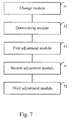
Fig. 7 is a block diagram showing another device for adjusting a liquid crystal display according to an exemplary embodiment. -
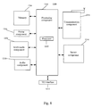
Fig. 8 is a block diagram showing a device for adjusting a liquid crystal display according to an exemplary embodiment. - Reference will now be made in detail to exemplary embodiments, examples of which are illustrated in the accompanying drawings. The following description refers to the accompanying drawings in which the same numbers in different drawings represent the same or similar elements unless otherwise represented. The implementations set forth in the following description of exemplary embodiments do not represent all implementations consistent with the invention. Instead, they are merely examples of apparatuses and methods consistent with aspects related to the invention as recited in the appended claims.
-
Fig. 1 is a flow chart showing a method for adjusting a liquid crystal display according to an exemplary embodiment. As shown inFig. 1 , the method for adjusting the liquid crystal display is used for a terminal device with the liquid crystal display, such as a mobile phone, a tablet, as an object to be adjusted, and includes the following steps S101 to S103. - In step S101, an on-load voltage across a source circuit of the liquid crystal display is changed, and transmittances of the liquid crystal display at different on-load voltages are measured.
- In an embodiment, the above step S101 may include: the on-load voltage is gradually increased or decreased according to a preset step size starting from a preset initial voltage, and the transmittance of the liquid crystal display at the increased or decreased on-load voltage is measured until the measured transmittance begins to decrease.
- The above step S101 may further include the following steps A1 to A2.
- In step A1, the step size currently used is decreased to obtain a new step size when the measured transmittance begins to decrease.
- In step A2, an operation of gradually decreasing or increasing the on-load voltage opposite to the increased or decreased operation executed before is performed according to the new step size starting from the current on-load voltage, and the transmittance of the liquid crystal display at the decreased or increased on-load voltages is measured until the measured transmittance begins to decrease.
- For example, a range of the on-load voltage of the source circuit is from 4V to 6V, the preset initial voltage is 4V, and the preset step size is 0.3V. The on-load voltage is gradually increased by 0.3V starting from 4V, and the transmittance of the liquid crystal display at the increased on-load voltage is measured until the measured transmittance begins to decrease. If the used step size is decreased to 0.1V, the on-load voltage is gradually decreased by 0.1V starting from the current on-load voltage, and the transmittance of the liquid crystal display at the decreased on-load voltage is measured until the measured transmittance begins to decrease. If the used step size is decreased to 0.05V, the on-load voltage is gradually increased by 0.05V starting from the current on-load voltage, and the transmittance of the liquid crystal display at the increased on-load voltage is measured until the measured transmittance begins to decrease. The above steps of decreasing and increasing the on-load voltage are repeated until the step size is decreased to a preset accuracy.
- In another example, the range of the on-load voltage of the source circuit is from 4V to 6V, the preset initial voltage is 6V, and the preset step size is 0.3V The on-load voltage is gradually decreased by 0.3V starting from 6V, and the transmittance of the liquid crystal display at the decreased on-load voltage is measured until the measured transmittance begins to decrease. If the used step size is decreased to 0.1V the on-load voltage is gradually increased by 0.1V starting from the current on-load voltage, and the transmittance of the liquid crystal display at the increased on-load voltage is measured until the measured transmittance begins to decrease. If the used step size is decreased to 0.05V, the on-load voltage is gradually decreased by 0.05V starting from the current on-load voltage, and the transmittance of the liquid crystal display at the decreased on-load voltage is measured until the measured transmittance begins to decrease. The above steps of decreasing and increasing the on-load voltage are repeated until the step size is decreased to a preset accuracy.
- In step S102, an on-load voltage corresponding to a maximum transmittance of the liquid crystal display is determined according to a corresponding relationship between the on-load voltage and the transmittance.
- In an embodiment, the above step S102 may include: a critical on-load voltage is determined according to the corresponding relationship between the on-load voltage and the transmittance, and the critical on-load voltage is set as the on-load voltage corresponding to the maximum transmittance;
- wherein, the transmittance of the liquid crystal display begins to decrease when the on-load voltage is larger or less than the critical on-load voltage.
- For example, as shown in
Fig. 2 , the critical on-load voltage is 5V, and the transmittance is the largest at the critical on-load voltage. When the on-load voltage is larger or less than the critical on-load voltage, the transmittance of the liquid crystal display begins to decrease. Since the critical on-load voltage of each liquid crystal display is different, the critical on-load voltage of each liquid crystal display is found by changing the on-load voltage across the source circuit of the liquid crystal display. - In step S103, an operation voltage of the source circuit is determined according to the on-load voltage corresponding to the maximum transmittance, and the on-load voltage across the source circuit is adjusted to the operation voltage.
- For example, taking the on-load voltage corresponding to the maximum transmittance as a center, the operation voltage of the source circuit is determined in a preset range, and the on-load voltage across the source circuit is adjusted to the operation voltage. For example, if the on-load voltage corresponding to the maximum transmittance is 5.2V, taking the on-load voltage 5.2V corresponding to the maximum transmittance as a center, the operation voltage of the source circuit determined in the preset range of 4.8V to 5.6V is 5V, and the on-load voltage across the source circuit is adjusted to 5V.
- The technical solutions provided by the embodiments of the present invention may include the following advantageous effects: by adjusting the operation voltage of the source circuit to the voltage corresponding to the maximum transmittance of the liquid crystal display, the transmittance of the liquid crystal display is increased, and then the brightness of the liquid crystal display is increased, whereby the brightness of the liquid crystal display may be increased while the structure of the liquid crystal display does not change.
-
Fig. 3 is a flow chart showing another method for adjusting a liquid crystal display according to an exemplary embodiment. As shown inFig. 3 , the method for adjusting the liquid crystal display is used for a terminal device with the liquid crystal display, such as a mobile phone, a tablet, as an object to be adjusted, and includes the following steps. - In step S301, an on-load voltage across a source circuit of the liquid crystal display is changed, and transmittances of the liquid crystal display at different on-load voltages are measured.
- In step S302, an on-load voltage corresponding to a maximum transmittance of the liquid crystal display is determined according to a corresponding relationship between the on-load voltage and the transmittance.
- In step S303, an operation voltage of the source circuit is determined according to the on-load voltage corresponding to the maximum transmittance, and the on-load voltage across the source circuit is adjusted to the operation voltage.
- The exemplary explanations of the above steps S301 to S303 refer to the exemplary explanations in steps S101 to S103, which are not described herein anymore.
- In step S304, color temperature of the liquid crystal display is adjusted to a preset color temperature value in the case that the on-load voltage of the source circuit is kept to the determined operation voltage.
- For example, the preset color temperature value is 6500K, and in the case that the on-load voltage of the source circuit is kept to the determined operation voltage, the voltages of three colors red, green, blue RGB are adjusted, and the color temperature of the liquid crystal display is gradually measured until the color temperature value is adjusted to 6500K.
- In step S305, a gamma ray value of the liquid crystal display is adjusted to a preset gamma ray value in the case that the on-load voltage of the source circuit is kept to the determined operation voltage and the color temperature is adjusted to the preset color temperature value.
- For example, the preset gamma ray value is 2.2, and in the case that the on-load voltage of the source circuit is kept to the determined operation voltage and the color temperature is adjusted to the preset color temperature value, each gray-scale voltage is adjusted so that the gamma ray value is 2.2.
- The technical solutions provided by the embodiments of the present invention may include the following advantageous effects: on the premise of ensuring the brightness of the liquid crystal display, the display effect of the image will be better.
-
Fig. 4 is a flow chart showing a method for adjusting a liquid crystal display according to an exemplary embodiment. As shown inFig. 4 , the method for adjusting the liquid crystal display takes a terminal device with the liquid crystal display, such as a mobile phone, a tablet, as an object to be adjusted, and includes the following steps. - In step S401, the on-load voltage is gradually increased according to a preset step size starting from a preset initial voltage, and the transmittance of the liquid crystal display at the increased on-load voltage is measured until the measured transmittance begins to decrease.
- In step S402, the step size currently used is decreased to obtain a new step size when the measured transmittance begins to decrease.
- In step S403, an operation of decreasing or increasing the on-load voltage opposite to the increased or decreased operation before is gradually performed according to the new step size starting from the current on-load voltage, and the transmittance of the liquid crystal display at the decreased or increased on-load voltages is measured until the measured transmittance begins to decrease.
- In step S404, the above step S402 and step S403 are repeated until the step size is decreased to a preset accuracy.
- In step S405, color temperature of the liquid crystal display is adjusted to a preset color temperature value in the case that the on-load voltage of the source circuit is kept to the determined operation voltage.
- In step S406, a gamma ray value of the liquid crystal display is adjusted to a preset gamma ray value in the case that the on-load voltage of the source circuit is kept to the determined operation voltage and the color temperature is adjusted to the preset color temperature value.
- The technical solutions provided by the embodiments of the present invention may include the following advantageous effect: the image may be better displayed while ensuring the brightness of the liquid crystal display.
-
Fig. 5 is a block diagram showing an apparatus for adjusting a liquid crystal display according to an exemplary embodiment. As shown inFig. 5 , the apparatus for adjusting the liquid crystal display is used for a terminal device with the liquid crystal display, such as a mobile phone, a tablet, as an object to be adjusted, and includes: - a
change module 51 configured to change an on-load voltage across a source circuit of the liquid crystal display, and measure transmittance of the liquid crystal display at different on-load voltages; - a determining
module 52 configured to determine an on-load voltage corresponding to a maximum transmittance of the liquid crystal display according to a corresponding relationship between the on-load voltage and the transmittance; and - a
first adjustment module 53 configured to determine an operation voltage of the source circuit according to the on-load voltage corresponding to the maximum transmittance, and adjust the on-load voltage across the source circuit to the operation voltage. - In an embodiment, as shown in
Fig. 6 , thechange module 51 may include: - a
first change sub-module 61 configured to gradually increase or decrease the on-load voltage according to a preset step size starting from a preset initial voltage, and measure the transmittance of the liquid crystal display at the increased or decreased on-load voltage until the measured transmittance begins to decrease. - In an embodiment, the
change module 51 may include: - a
decrease sub-module 62 configured to decrease the step size currently used to obtain a new step size when the measured transmittance begins to decrease; and - a
second change sub-module 63 configured to perform an operation of gradually decreasing or increasing the on-load voltage opposite to the increased or decreased operation before according to the new step size starting from the current on-load voltage, and measure the transmittance of the liquid crystal display at the decreased or increased on-load voltages until the measured transmittance begins to decrease. - In an embodiment, the determining module may include:
- a determining sub-module configured to determine a critical on-load voltage according to the corresponding relationship between the on-load voltage and the transmittance, and set the critical on-load voltage as the on-load voltage corresponding to the maximum transmittance;
- wherein, the transmittance of the liquid crystal display begins to decrease when the on-load voltage is larger or less than the critical on-load voltage.
- In an embodiment, as shown in
Fig. 7 , the apparatus may further include: - a
second adjustment module 71 configured to adjust color temperature of the liquid crystal display to a preset color temperature value in the case that the on-load voltage of the source circuit is kept to the determined operation voltage. - In an embodiment, as shown in
Fig. 7 , the apparatus may further include: - a
third adjustment module 72 configured to adjust a gamma ray value of the liquid crystal display to a preset gamma ray value in the case that the on-load voltage of the source circuit is kept to the determined operation voltage and the color temperature is adjusted to the preset color temperature value. - With regard to the device in the above embodiment, detailed description of specific manner for conducting operation of modules has been made in the embodiment related to the method, and no detailed illustration will be made herein.
- The technical solutions provided by the embodiments of the present invention may include the following advantageous effects: by adjusting the operation voltage of the source circuit to the voltage corresponding to the maximum transmittance of the liquid crystal display, the transmittance of the liquid crystal display is increased, and then the brightness of the liquid crystal display is increased, whereby the brightness of the liquid crystal display may be increased without changing the structure of the liquid crystal display.
-
Fig. 8 is a block diagram showing adevice 1200 for adjusting a liquid crystal display according to an exemplary embodiment, and the device is used to a terminal device. For example, thedevice 1200 may be a mobile phone, a computer, a digital broadcast terminal, a messaging device, a gaming console, a tablet, a medical device, exercise equipment, a personal digital assistant (PDA), and the like. - Referring to
Fig. 8 , thedevice 1200 may include one or more of the following components: aprocessing component 1202, amemory 1204, apower component 1206, amultimedia component 1208, anaudio component 1210, an input/output (I/O)interface 1212, asensor component 1214, and acommunication component 1216. - The
processing component 1202 usually controls overall operations of thedevice 1200, such as the operations associated with display, telephone calls, data communications, camera operations, and recording operations. Theprocessing component 1202 may include one ormore processors 1220 to execute instructions to perform all or part of the steps in the above described methods. Moreover, theprocessing component 1202 may include one or more modules which facilitate the interaction between theprocessing component 1202 and other components. For instance, theprocessing component 1202 may include a multimedia module to facilitate the interaction between themultimedia component 1208 and theprocessing component 1202. - The
memory 1204 is configured to store various types of data to support the operation of thedevice 1200. Examples of such data include instructions for any application or method operated on thedevice 1200, contact data, phonebook data, messages, pictures, videos, etc. Thememory 1204 may be implemented using any type of volatile or non-volatile memory device or combination thereof, such as a static random access memory (SRAM), an electrically erasable programmable read-only memory (EEPROM), an erasable programmable read-only memory (EPROM), a programmable read-only memory (PROM), a read-only memory (ROM), a magnetic memory, a flash memory, a magnetic or optical disk. - The
power component 1206 provides power to various components of thedevice 1200. Thepower component 1206 may include a power management system, one or more power sources, and other components associated with the generation, management, and distribution of power in thedevice 1200. - The
multimedia component 1208 includes a screen providing an output interface between thedevice 1200 and the user. In some embodiments, the screen may include a liquid crystal display (LCD) and a touch panel (TP). If the screen includes the touch panel, the screen may be implemented as a touch screen to receive input signals from the user. The touch panel includes one or more touch sensors to sense touches, slips, and gestures on the touch panel. The touch sensors may not only sense a boundary of a touch or slip action, but also sense a period of time and a pressure associated with the touch or slip action. In some embodiments, themultimedia component 1208 includes a front camera and/or a rear camera. The front camera and/or the rear camera may receive an external multimedia datum while thedevice 1200 is in an operation manner, such as a photographing manner or a video manner. Each of the front camera and the rear camera may be a fixed optical lens system or have focus and optical zoom capability. - The
audio component 1210 is configured to output and/or input audio signals. For example, theaudio component 1210 includes a microphone (MIC) configured to receive an external audio signal when thedevice 1200 is in an operation manner, such as a call manner, a recording manner, and a voice identification manner. The received audio signal may be further stored in thememory 1204 or transmitted via thecommunication component 1216. In some embodiments, theaudio component 1210 further includes a speaker to output audio signals. - The I/
O interface 1212 provides an interface between theprocessing component 1202 and peripheral interface modules, such as a keyboard, a click wheel, a button, and the like. The button may include, but not limited to, a home button, a volume button, a starting button, and a locking button. - The
sensor component 1214 includes one or more sensors to provide status assessments of various aspects of thedevice 1200. For instance, thesensor component 1214 may detect an open/closed status of thedevice 1200, relative positioning of components, e.g., the display and the keyboard, of thedevice 1200, a change in position of thedevice 1200 or a component of thedevice 1200, a presence or absence of user contact with thedevice 1200, an orientation or an acceleration/deceleration of thedevice 1200, and a change in temperature of thedevice 1200. Thesensor component 1214 may include a proximity sensor configured to detect the presence of nearby objects without any physical contact. Thesensor component 1214 may also include a light sensor, such as a CMOS or CCD image sensor, for use in imaging applications. In some embodiments, thesensor component 1214 may also include an accelerometer sensor, a gyroscope sensor, a magnetic sensor, a pressure sensor, or a temperature sensor. - The
communication component 1216 is configured to facilitate communication, wired or wirelessly, between thedevice 1200 and other devices. Thedevice 1200 may access a wireless network based on a communication standard, such as WI-FI, 2G, or 3G, or a combination thereof. In one exemplary embodiment, thecommunication component 1216 receives a broadcast signal or broadcast associated information from an external broadcast management system via a broadcast channel. In one exemplary embodiment, thecommunication component 1216 further includes a near field communication (NFC) module to facilitate short-range communications. For example, the NFC module may be implemented based on a radio frequency identification (RFID) technology, an infrared data association (IrDA) technology, an ultra-wideband (UWB) technology, a Bluetooth (BT) technology, and other technologies. - In exemplary embodiments, the
device 1200 may be implemented with one or more application specific integrated circuits (ASICs), digital signal processors (DSPs), digital signal processing devices (DSPDs), programmable logic devices (PLDs), field programmable gate arrays (FPGAs), controllers, micro-controllers, microprocessors, or other electronic components, for performing the above method. - In exemplary embodiments, there is also provided a non-transitory computer readable storage medium including instructions, such as included in the
memory 1204, executable by the processor 820 in thedevice 1200, for performing the above method. For example, the non-transitory computer-readable storage medium may be a ROM, a random access memory (RAM), a CD-ROM, a magnetic tape, a floppy disc, an optical data storage device, and the like. - According to an embodiment of the invention, there is provided a device for adjusting a liquid crystal display, including:
- a processor; and
- a memory for storing instructions executable by the processor;
- wherein the processor is configured to:
- change an on-load voltage across a source circuit of the liquid crystal display, and measure transmittance of the liquid crystal display at different on-load voltages;
- determine an on-load voltage corresponding to a maximum transmittance of the liquid crystal display according to a corresponding relationship between the on-load voltage and the transmittance; and
- determine an operation voltage of the source circuit according to the on-load voltage corresponding to the maximum transmittance, and adjust the on-load voltage across the source circuit to the operation voltage.
- The processor may also be configured to: gradually increase or decreasing the on-load voltage according to a preset step size starting from a preset initial voltage, and measure the transmittance of the liquid crystal display at the increased or decreased on-load voltage until the measured transmittance begins to decrease.
- The processor may also be configured to: decrease the step size currently used to obtain a new step size when the measured transmittance begins to decrease; and perform an operation of gradually decreasing or increasing the on-load voltage opposite to the increased or decreased operation before according to the new step size starting from the current on-load voltage, and measure the transmittance of the liquid crystal display at the decreased or increased on-load voltages until the measured transmittance begins to decrease.
- The processor may also be configured to: determine a critical on-load voltage according to the corresponding relationship between the on-load voltage and the transmittance, and use the critical on-load voltage as the on-load voltage corresponding to the maximum transmittance; wherein, the transmittance of the liquid crystal display begins to decrease when the on-load voltage is larger or less than the critical on-load voltage.
- The processor may also be configured to: adjust color temperature of the liquid crystal display to a preset color temperature value in the case that the on-load voltage of the source circuit is kept to the determined operation voltage.
- The processor may also be configured to: adjust a gamma ray value of the liquid crystal display to a preset gamma ray value in the case that the on-load voltage of the source circuit is kept to the determined operation voltage and the color temperature is adjusted to the preset color temperature value.
- A non-transitory computer readable storage medium, when instructions in the storage medium are executed by the processor of an apparatus such as e.g. a terminal, the apparatus may execute a method for adjusting a liquid crystal display, the method includes:
- changing an on-load voltage across a source circuit of the liquid crystal display, and measuring transmittances of the liquid crystal display at different on-load voltages;
- determining an on-load voltage corresponding to a maximum transmittance of the liquid crystal display according to a corresponding relationship between the on-load voltage and the transmittance; and
- determining an operation voltage of the source circuit according to the on-load voltage corresponding to the maximum transmittance, and adjusting the on-load voltage across the source circuit to the operation voltage.
- The changing the on-load voltage across the source circuit of the liquid crystal display, and measuring transmittances of the liquid crystal display at different on-load voltages may include:
- gradually increasing or decreasing the on-load voltage according to a preset step size starting from a preset initial voltage, and measuring transmittances of the liquid crystal display at the increased or decreased on-load voltage until the measured transmittance begins to decrease.
- The changing the on-load voltage across the source circuit of the liquid crystal display, and measuring transmittances of the liquid crystal display at different on-load voltages may include:
- decreasing the step size currently used to obtain a new step size when the measured transmittance begins to decrease; and
- performing an operation of gradually decreasing or increasing the on-load voltage opposite to the increased or decreased operation before according to the new step size starting from the current on-load voltage, and measuring transmittances of the liquid crystal display at the decreased or increased on-load voltages until the measured transmittance begins to decrease.
- The determining the on-load voltage corresponding to the maximum transmittance of the liquid crystal display according to the corresponding relationship between the on-load voltage and the transmittance may include:
- determining a critical on-load voltage according to the corresponding relationship between the on-load voltage and the transmittance, and using the critical on-load voltage as the on-load voltage corresponding to the maximum transmittance;
- wherein, the transmittance of the liquid crystal display begins to decrease when the on-load voltage is larger or less than the critical on-load voltage.
- The method may further include: adjusting color temperature of the liquid crystal display to a preset color temperature value in the case that the on-load voltage of the source circuit is kept to the determined operation voltage.
- The method may further include: adjusting a gamma ray value of the liquid crystal display to a preset gamma ray value in the case that the on-load voltage of the source circuit is kept to the determined operation voltage and the color temperature is adjusted to the preset color temperature value.
- After considering this description and carrying out the embodiments disclosed herein, those skilled in the art may easy anticipate other implementation aspects of the present invention. The present invention is meant to cover any variations, usage or adaptive change of these embodiments, and these variations, usage or adaptive change follow general concept of the present invention and include the often-used knowledge or the customary technical means in the technical field that is not disclosed in the present invention. The description and embodiments are only exemplary, and the real range and spirit of the present invention are defined by the following claims.
Claims (14)
- A method for adjusting a liquid crystal display, characterized by comprising:changing (S101, S301) an on-load voltage across a source circuit of the liquid crystal display, and measuring transmittances of the liquid crystal display at different on-load voltages;determining (S102, S302) an on-load voltage corresponding to a maximum transmittance of the liquid crystal display according to a corresponding relationship between the on-load voltage and the transmittance; anddetermining (S103, S303) an operation voltage of the source circuit according to the on-load voltage corresponding to the maximum transmittance, and adjusting the on-load voltage across the source circuit to the operation voltage.
- The method according to claim 1, characterized in that, the changing the on-load voltage across the source circuit of the liquid crystal display, and measuring transmittances of the liquid crystal display at different on-load voltages comprises:gradually increasing or decreasing (S401, S402) the on-load voltage according to a preset step size starting from a preset initial voltage, and measuring transmittances of the liquid crystal display at the increased or decreased on-load voltage until the measured transmittance begins to decrease.
- The method according to claim 2, characterized in that, the changing the on-load voltage across the source circuit of the liquid crystal display, and measuring transmittances of the liquid crystal display at different on-load voltages comprises:decreasing (S403) the step size currently used to obtain a new step size when the measured transmittance begins to decrease; andperforming (S404) an operation of gradually decreasing or increasing the on-load voltage opposite to the increased or decreased operation before according to the new step size starting from the current on-load voltage, and measuring transmittances of the liquid crystal display at the decreased or increased on-load voltages until the measured transmittance begins to decrease.
- The method according to claim 1, characterized in that, the determining the on-load voltage corresponding to the maximum transmittance of the liquid crystal display according to the corresponding relationship between the on-load voltage and the transmittance comprises:determining a critical on-load voltage according to the corresponding relationship between the on-load voltage and the transmittance, and using the critical on-load voltage as the on-load voltage corresponding to the maximum transmittance;wherein, the transmittance of the liquid crystal display begins to decrease when the on-load voltage is larger or less than the critical on-load voltage.
- The method according to claim 1, characterized in that, the method further comprises:adjusting (S304, S405) color temperature of the liquid crystal display to a preset color temperature value in the case that the on-load voltage of the source circuit is kept to the determined operation voltage.
- The method according to claim 5, characterized in that, the method further comprises:adjusting (S305, S406) a gamma ray value of the liquid crystal display to a preset gamma ray value in the case that the on-load voltage of the source circuit is kept to the determined operation voltage and the color temperature is adjusted to the preset color temperature value.
- An apparatus for adjusting a liquid crystal display, characterized by comprising:a change module (51) configured to change an on-load voltage across a source circuit of the liquid crystal display, and measure transmittances of the liquid crystal display at different on-load voltages;a determining module (52) configured to determine an on-load voltage corresponding to a maximum transmittance of the liquid crystal display according to a corresponding relationship between the on-load voltage and the transmittance; anda first adjustment module (53) configured to determine an operation voltage of the source circuit according to the on-load voltage corresponding to the maximum transmittance, and adjust the on-load voltage across the source circuit to the operation voltage.
- The apparatus according to claim 7, characterized in that, the change module (51) comprises:a first change sub-module (61) configured to gradually increase or decrease the on-load voltage according to a preset step size starting from a preset initial voltage, and measure the transmittance of the liquid crystal display at the increased or decreased on-load voltage until the measured transmittance begins to decrease.
- The apparatus according to claim 8, characterized in that, the change module (51) comprises:a decrease sub-module (62) configured to decrease the step size currently used to obtain a new step size when the measured transmittance begins to decrease; anda second change sub-module (63) configured to perform an operation of gradually decreasing or increasing the on-load voltage opposite to the increased or decreased operation before according to the new step size starting from the current on-load voltage, and measure the transmittance of the liquid crystal display at the decreased or increased on-load voltages until the measured transmittance begins to decrease.
- The apparatus according to claim 7, characterized in that, the determining module (52) comprises:a determining sub-module configured to determine a critical on-load voltage according to the corresponding relationship between the on-load voltage and the transmittance, and set the critical on-load voltage as the on-load voltage corresponding to the maximum transmittance;wherein, the transmittance of the liquid crystal display begins to decrease when the on-load voltage is larger or less than the critical on-load voltage.
- The apparatus according to claim 7, characterized in that, the apparatus further comprises:a second adjustment module (71) configured to adjust color temperature of the liquid crystal display to a preset color temperature value in the case that the on-load voltage of the source circuit is kept to the determined operation voltage.
- The apparatus according to claim 11, characterized in that, the apparatus further comprises:a third adjustment module (73) configured to adjust a gamma ray value of the liquid crystal display to a preset gamma ray value in the case that the on-load voltage of the source circuit is kept to the determined operation voltage and the color temperature is adjusted to the preset color temperature value.
- A device for adjusting a liquid crystal display, characterized by comprising:a processor; anda memory for storing instructions executable by the processor;wherein the processor is configured to:change an on-load voltage across a source circuit of the liquid crystal display, and measure transmittances of the liquid crystal display at different on-load voltages;determine an on-load voltage corresponding to a maximum transmittance of the liquid crystal display according to a corresponding relationship between the on-load voltage and the transmittance; anddetermine an operation voltage of the source circuit according to the on-load voltage corresponding to the maximum transmittance, and adjust the on-load voltage across the source circuit to the operation voltage.
- A computer program product stored on a computer usable medium, comprising computer-readable program means for causing an apparatus to implement the method according to any one of claims 1 to 6.
Applications Claiming Priority (1)
| Application Number | Priority Date | Filing Date | Title |
|---|---|---|---|
| CN201410835876.8A CN104464674B (en) | 2014-12-26 | 2014-12-26 | Liquid crystal display method of adjustment and device |
Publications (1)
| Publication Number | Publication Date |
|---|---|
| EP3038081A1 true EP3038081A1 (en) | 2016-06-29 |
Family
ID=52910631
Family Applications (1)
| Application Number | Title | Priority Date | Filing Date |
|---|---|---|---|
| EP15202344.6A Ceased EP3038081A1 (en) | 2014-12-26 | 2015-12-23 | Method for adjusting liquid crystal display and apparatus thereof |
Country Status (9)
| Country | Link |
|---|---|
| US (1) | US10109248B2 (en) |
| EP (1) | EP3038081A1 (en) |
| JP (1) | JP2017505465A (en) |
| KR (1) | KR101845506B1 (en) |
| CN (1) | CN104464674B (en) |
| BR (1) | BR112015027548A2 (en) |
| MX (1) | MX362249B (en) |
| RU (1) | RU2627930C2 (en) |
| WO (1) | WO2016101478A1 (en) |
Families Citing this family (6)
| Publication number | Priority date | Publication date | Assignee | Title |
|---|---|---|---|---|
| CN104464674B (en) * | 2014-12-26 | 2017-12-08 | 小米科技有限责任公司 | Liquid crystal display method of adjustment and device |
| CN109061921B (en) * | 2018-08-14 | 2021-03-02 | Oppo广东移动通信有限公司 | Preparation method and device of color-changing assembly and electronic equipment |
| CN109003589A (en) * | 2018-08-15 | 2018-12-14 | 京东方科技集团股份有限公司 | A kind of method and device, display device adjusting Gamma reference voltage |
| CN109559707B (en) * | 2018-12-26 | 2020-11-24 | 惠科股份有限公司 | Gamma value processing method and device of display panel and display equipment |
| CN111028808B (en) * | 2019-12-24 | 2021-10-08 | 惠州市华星光电技术有限公司 | Method, device and system for adjusting brightness and visual angle of liquid crystal panel and display device |
| CN111585319B (en) * | 2020-04-20 | 2021-12-14 | 维沃移动通信有限公司 | Camera power supply method, device, electronic device and storage medium |
Citations (3)
| Publication number | Priority date | Publication date | Assignee | Title |
|---|---|---|---|---|
| US5555205A (en) * | 1993-04-27 | 1996-09-10 | Dai Nippon Printing Co., Ltd. | Method device for recording information, and method for measuring the transmittance of liquid crystals, which is applied to recording information |
| US20070236433A1 (en) * | 2006-04-05 | 2007-10-11 | Seiko Epson Corporation | Control method and control apparatus for liquid crystal display |
| WO2014190644A1 (en) * | 2013-05-31 | 2014-12-04 | 京东方科技集团股份有限公司 | Gamma curve adjustment method and gamma curve adjustment device |
Family Cites Families (24)
| Publication number | Priority date | Publication date | Assignee | Title |
|---|---|---|---|---|
| JPS5999368A (en) * | 1982-11-30 | 1984-06-08 | Rohm Co Ltd | Method and apparatus for measuring inverse voltage of semiconductor element |
| JP2862456B2 (en) * | 1993-04-27 | 1999-03-03 | 大日本印刷株式会社 | Information recording method using liquid crystal recording medium |
| JP2000105363A (en) * | 1998-07-29 | 2000-04-11 | Matsushita Electric Ind Co Ltd | Liquid crystal display device and driving method of liquid crystal display device |
| JP2000172218A (en) * | 1998-12-03 | 2000-06-23 | Matsushita Electric Ind Co Ltd | Liquid crystal display |
| KR20020080332A (en) * | 1999-10-26 | 2002-10-23 | 마츠시타 덴끼 산교 가부시키가이샤 | Liquid crystal display and method for manufacturing the same, and method for driving liquid crystal display |
| JP3668839B2 (en) * | 1999-10-26 | 2005-07-06 | 松下電器産業株式会社 | LIQUID CRYSTAL DISPLAY DEVICE, ITS MANUFACTURING METHOD, AND LIQUID CRYSTAL DISPLAY DEVICE DRIVE METHOD |
| JP2003157056A (en) * | 2001-11-20 | 2003-05-30 | Matsushita Electric Ind Co Ltd | Gamma correction method for liquid crystal display |
| US7952555B2 (en) * | 2003-11-19 | 2011-05-31 | Eizo Nanao Corporation | Luminance control method, liquid crystal display device and computer program |
| JP3976095B2 (en) * | 2004-05-27 | 2007-09-12 | 株式会社ナナオ | Gamma value acquisition method for liquid crystal display device, gamma value acquisition system for realizing the same, computer for acquiring the same, and program used therefor |
| JP4015157B2 (en) * | 2004-07-20 | 2007-11-28 | シャープ株式会社 | Drive device for liquid crystal display device, program and recording medium, and liquid crystal display device |
| JP2006163290A (en) * | 2004-12-10 | 2006-06-22 | Canon Inc | Image display device |
| JP3952067B2 (en) * | 2005-06-10 | 2007-08-01 | セイコーエプソン株式会社 | Display device, electro-optical device driving method, and electronic apparatus |
| CN101393727B (en) | 2007-09-21 | 2011-07-20 | 北京京东方光电科技有限公司 | Highly dynamic contrast processing apparatus and method for LCD device |
| JP2009294364A (en) | 2008-06-04 | 2009-12-17 | Sharp Corp | Residual dc measuring device, residual dc measuring system, residual dc measuring method, residual dc measuring device control program, computer readable recording medium |
| CN100594538C (en) * | 2008-07-14 | 2010-03-17 | 上海广电光电子有限公司 | Color temperature modulation method of liquid crystal display |
| KR101330353B1 (en) | 2008-08-08 | 2013-11-20 | 엘지디스플레이 주식회사 | Liquid Crystal Display and Driving Method thereof |
| KR101362169B1 (en) | 2008-09-24 | 2014-02-13 | 엘지디스플레이 주식회사 | Gamma Correction System and its Correction Method |
| CN101685207B (en) * | 2008-09-27 | 2011-12-28 | 北京京东方光电科技有限公司 | Measuring method and device |
| JP4668342B2 (en) * | 2009-08-31 | 2011-04-13 | シャープ株式会社 | Liquid crystal display device |
| CN102110421B (en) * | 2009-12-28 | 2013-11-06 | 京东方科技集团股份有限公司 | Gray-scale adjustment method and device |
| CN102467862B (en) | 2010-11-17 | 2014-08-27 | 京东方科技集团股份有限公司 | Voltage regulation method and device of liquid crystal display panel |
| CN102708814B (en) * | 2011-07-29 | 2015-04-29 | 京东方科技集团股份有限公司 | Alternating-current test method and system for relation curve of voltage and transmittance of liquid crystal display (LCD) module |
| CN103413513B (en) * | 2013-07-22 | 2016-03-30 | 北京京东方光电科技有限公司 | A kind of method of adjustment and device showing module driving voltage |
| CN104464674B (en) * | 2014-12-26 | 2017-12-08 | 小米科技有限责任公司 | Liquid crystal display method of adjustment and device |
-
2014
- 2014-12-26 CN CN201410835876.8A patent/CN104464674B/en active Active
-
2015
- 2015-04-29 BR BR112015027548A patent/BR112015027548A2/en not_active Application Discontinuation
- 2015-04-29 JP JP2016565539A patent/JP2017505465A/en active Pending
- 2015-04-29 KR KR1020157015964A patent/KR101845506B1/en active Active
- 2015-04-29 RU RU2015138994A patent/RU2627930C2/en active
- 2015-04-29 WO PCT/CN2015/077825 patent/WO2016101478A1/en not_active Ceased
- 2015-04-29 MX MX2015012096A patent/MX362249B/en active IP Right Grant
- 2015-12-23 EP EP15202344.6A patent/EP3038081A1/en not_active Ceased
-
2016
- 2016-12-14 US US15/378,540 patent/US10109248B2/en active Active
Patent Citations (4)
| Publication number | Priority date | Publication date | Assignee | Title |
|---|---|---|---|---|
| US5555205A (en) * | 1993-04-27 | 1996-09-10 | Dai Nippon Printing Co., Ltd. | Method device for recording information, and method for measuring the transmittance of liquid crystals, which is applied to recording information |
| US20070236433A1 (en) * | 2006-04-05 | 2007-10-11 | Seiko Epson Corporation | Control method and control apparatus for liquid crystal display |
| WO2014190644A1 (en) * | 2013-05-31 | 2014-12-04 | 京东方科技集团股份有限公司 | Gamma curve adjustment method and gamma curve adjustment device |
| US20150243198A1 (en) * | 2013-05-31 | 2015-08-27 | Boe Technology Group Co., Ltd. | Gamma curve adjustment method and gamma curve adjustment apparatus |
Non-Patent Citations (1)
| Title |
|---|
| "HP 4140B data sheet", 1 March 1987 (1987-03-01), XP055259783, Retrieved from the Internet <URL:http://www.keysight.com/upload/cmc_upload/All/04140-90021.pdf?&cc=DE&lc=ger> [retrieved on 20160318] * |
Also Published As
| Publication number | Publication date |
|---|---|
| KR20160091245A (en) | 2016-08-02 |
| MX2015012096A (en) | 2017-02-28 |
| US20170092213A1 (en) | 2017-03-30 |
| CN104464674A (en) | 2015-03-25 |
| RU2627930C2 (en) | 2017-08-14 |
| KR101845506B1 (en) | 2018-04-04 |
| RU2015138994A (en) | 2017-03-16 |
| MX362249B (en) | 2019-01-09 |
| JP2017505465A (en) | 2017-02-16 |
| WO2016101478A1 (en) | 2016-06-30 |
| BR112015027548A2 (en) | 2017-09-12 |
| CN104464674B (en) | 2017-12-08 |
| US10109248B2 (en) | 2018-10-23 |
Similar Documents
| Publication | Publication Date | Title |
|---|---|---|
| US11015973B2 (en) | Method and apparatus for acquiring ambient light brightness based on the luminance value of the screen of a terminal device | |
| US10032076B2 (en) | Method and device for displaying image | |
| US9858885B2 (en) | Method and device for reducing display brightness | |
| RU2630167C1 (en) | Method and device for switching colour range mode | |
| JP7166171B2 (en) | INTERFACE IMAGE DISPLAY METHOD, APPARATUS AND PROGRAM | |
| US10109248B2 (en) | Method and device for adjusting liquid crystal display | |
| EP3032821A1 (en) | Method and device for shooting a picture | |
| CN112033527B (en) | Ambient brightness detection method, device, equipment and storage medium | |
| WO2017080055A1 (en) | Liquid crystal display method and apparatus | |
| US10013151B2 (en) | Method and terminal device for adjusting widget | |
| CN104238890B (en) | Character displaying method and device | |
| CN104182967B (en) | image processing method, device and terminal | |
| CN104536713B (en) | Method and device for displaying characters in image | |
| CN112019680A (en) | Screen brightness adjustment method and device | |
| CN108184103A (en) | The method and apparatus for showing image | |
| US9641737B2 (en) | Method and device for time-delay photographing | |
| EP3629318A2 (en) | Method and apparatus for compensating operating parameter of display circuit | |
| CN108538261B (en) | Method and device for controlling display, and display device | |
| CN105808096A (en) | Sliding block display method and apparatus | |
| CN107958652A (en) | Array base palte, electronic equipment | |
| CN106775541B (en) | Electronic device and screen display method | |
| CN111383608A (en) | Display control method and apparatus, electronic device, and computer-readable storage medium | |
| CN111383568A (en) | Display control method and apparatus, electronic device, and computer-readable storage medium | |
| CN108877702B (en) | Method and device for displaying image | |
| CN111383583A (en) | Display control method and apparatus, electronic device, and computer-readable storage medium |
Legal Events
| Date | Code | Title | Description |
|---|---|---|---|
| PUAI | Public reference made under article 153(3) epc to a published international application that has entered the european phase |
Free format text: ORIGINAL CODE: 0009012 |
|
| AK | Designated contracting states |
Kind code of ref document: A1 Designated state(s): AL AT BE BG CH CY CZ DE DK EE ES FI FR GB GR HR HU IE IS IT LI LT LU LV MC MK MT NL NO PL PT RO RS SE SI SK SM TR |
|
| AX | Request for extension of the european patent |
Extension state: BA ME |
|
| STAA | Information on the status of an ep patent application or granted ep patent |
Free format text: STATUS: REQUEST FOR EXAMINATION WAS MADE |
|
| 17P | Request for examination filed |
Effective date: 20161222 |
|
| RBV | Designated contracting states (corrected) |
Designated state(s): AL AT BE BG CH CY CZ DE DK EE ES FI FR GB GR HR HU IE IS IT LI LT LU LV MC MK MT NL NO PL PT RO RS SE SI SK SM TR |
|
| STAA | Information on the status of an ep patent application or granted ep patent |
Free format text: STATUS: EXAMINATION IS IN PROGRESS |
|
| 17Q | First examination report despatched |
Effective date: 20170810 |
|
| STAA | Information on the status of an ep patent application or granted ep patent |
Free format text: STATUS: THE APPLICATION HAS BEEN REFUSED |
|
| 18R | Application refused |
Effective date: 20190124 |