EP3036975B1 - Commande d'un système d'éclairage - Google Patents
Commande d'un système d'éclairage Download PDFInfo
- Publication number
- EP3036975B1 EP3036975B1 EP14759321.4A EP14759321A EP3036975B1 EP 3036975 B1 EP3036975 B1 EP 3036975B1 EP 14759321 A EP14759321 A EP 14759321A EP 3036975 B1 EP3036975 B1 EP 3036975B1
- Authority
- EP
- European Patent Office
- Prior art keywords
- user
- wireless
- user device
- lighting system
- region
- Prior art date
- Legal status (The legal status is an assumption and is not a legal conclusion. Google has not performed a legal analysis and makes no representation as to the accuracy of the status listed.)
- Not-in-force
Links
- 230000004044 response Effects 0.000 claims description 23
- 230000033001 locomotion Effects 0.000 claims description 9
- 230000000704 physical effect Effects 0.000 claims description 6
- 230000002547 anomalous effect Effects 0.000 claims description 5
- 238000004590 computer program Methods 0.000 claims description 4
- 238000005259 measurement Methods 0.000 description 12
- 238000000034 method Methods 0.000 description 8
- 230000009471 action Effects 0.000 description 7
- 238000010586 diagram Methods 0.000 description 5
- 230000006870 function Effects 0.000 description 5
- 238000012360 testing method Methods 0.000 description 5
- 238000001514 detection method Methods 0.000 description 4
- 238000004891 communication Methods 0.000 description 3
- 230000003993 interaction Effects 0.000 description 3
- 238000013507 mapping Methods 0.000 description 3
- 238000012545 processing Methods 0.000 description 3
- 238000002604 ultrasonography Methods 0.000 description 3
- 241000282412 Homo Species 0.000 description 1
- 206010028813 Nausea Diseases 0.000 description 1
- 230000000903 blocking effect Effects 0.000 description 1
- 230000001413 cellular effect Effects 0.000 description 1
- 230000000694 effects Effects 0.000 description 1
- 206010015037 epilepsy Diseases 0.000 description 1
- 230000004807 localization Effects 0.000 description 1
- 230000008693 nausea Effects 0.000 description 1
- 230000003287 optical effect Effects 0.000 description 1
- 230000008569 process Effects 0.000 description 1
- 230000009467 reduction Effects 0.000 description 1
- 230000011664 signaling Effects 0.000 description 1
- 239000002699 waste material Substances 0.000 description 1
Images
Classifications
-
- H—ELECTRICITY
- H05—ELECTRIC TECHNIQUES NOT OTHERWISE PROVIDED FOR
- H05B—ELECTRIC HEATING; ELECTRIC LIGHT SOURCES NOT OTHERWISE PROVIDED FOR; CIRCUIT ARRANGEMENTS FOR ELECTRIC LIGHT SOURCES, IN GENERAL
- H05B47/00—Circuit arrangements for operating light sources in general, i.e. where the type of light source is not relevant
- H05B47/10—Controlling the light source
- H05B47/175—Controlling the light source by remote control
- H05B47/19—Controlling the light source by remote control via wireless transmission
-
- H—ELECTRICITY
- H05—ELECTRIC TECHNIQUES NOT OTHERWISE PROVIDED FOR
- H05B—ELECTRIC HEATING; ELECTRIC LIGHT SOURCES NOT OTHERWISE PROVIDED FOR; CIRCUIT ARRANGEMENTS FOR ELECTRIC LIGHT SOURCES, IN GENERAL
- H05B45/00—Circuit arrangements for operating light-emitting diodes [LED]
- H05B45/10—Controlling the intensity of the light
- H05B45/14—Controlling the intensity of the light using electrical feedback from LEDs or from LED modules
-
- H—ELECTRICITY
- H05—ELECTRIC TECHNIQUES NOT OTHERWISE PROVIDED FOR
- H05B—ELECTRIC HEATING; ELECTRIC LIGHT SOURCES NOT OTHERWISE PROVIDED FOR; CIRCUIT ARRANGEMENTS FOR ELECTRIC LIGHT SOURCES, IN GENERAL
- H05B47/00—Circuit arrangements for operating light sources in general, i.e. where the type of light source is not relevant
- H05B47/10—Controlling the light source
- H05B47/105—Controlling the light source in response to determined parameters
- H05B47/11—Controlling the light source in response to determined parameters by determining the brightness or colour temperature of ambient light
-
- H—ELECTRICITY
- H05—ELECTRIC TECHNIQUES NOT OTHERWISE PROVIDED FOR
- H05B—ELECTRIC HEATING; ELECTRIC LIGHT SOURCES NOT OTHERWISE PROVIDED FOR; CIRCUIT ARRANGEMENTS FOR ELECTRIC LIGHT SOURCES, IN GENERAL
- H05B47/00—Circuit arrangements for operating light sources in general, i.e. where the type of light source is not relevant
- H05B47/10—Controlling the light source
- H05B47/105—Controlling the light source in response to determined parameters
- H05B47/115—Controlling the light source in response to determined parameters by determining the presence or movement of objects or living beings
-
- H05B47/1965—
-
- H05B47/199—
-
- H—ELECTRICITY
- H05—ELECTRIC TECHNIQUES NOT OTHERWISE PROVIDED FOR
- H05B—ELECTRIC HEATING; ELECTRIC LIGHT SOURCES NOT OTHERWISE PROVIDED FOR; CIRCUIT ARRANGEMENTS FOR ELECTRIC LIGHT SOURCES, IN GENERAL
- H05B45/00—Circuit arrangements for operating light-emitting diodes [LED]
- H05B45/10—Controlling the intensity of the light
-
- H—ELECTRICITY
- H05—ELECTRIC TECHNIQUES NOT OTHERWISE PROVIDED FOR
- H05B—ELECTRIC HEATING; ELECTRIC LIGHT SOURCES NOT OTHERWISE PROVIDED FOR; CIRCUIT ARRANGEMENTS FOR ELECTRIC LIGHT SOURCES, IN GENERAL
- H05B47/00—Circuit arrangements for operating light sources in general, i.e. where the type of light source is not relevant
- H05B47/10—Controlling the light source
- H05B47/165—Controlling the light source following a pre-assigned programmed sequence; Logic control [LC]
-
- Y—GENERAL TAGGING OF NEW TECHNOLOGICAL DEVELOPMENTS; GENERAL TAGGING OF CROSS-SECTIONAL TECHNOLOGIES SPANNING OVER SEVERAL SECTIONS OF THE IPC; TECHNICAL SUBJECTS COVERED BY FORMER USPC CROSS-REFERENCE ART COLLECTIONS [XRACs] AND DIGESTS
- Y02—TECHNOLOGIES OR APPLICATIONS FOR MITIGATION OR ADAPTATION AGAINST CLIMATE CHANGE
- Y02B—CLIMATE CHANGE MITIGATION TECHNOLOGIES RELATED TO BUILDINGS, e.g. HOUSING, HOUSE APPLIANCES OR RELATED END-USER APPLICATIONS
- Y02B20/00—Energy efficient lighting technologies, e.g. halogen lamps or gas discharge lamps
- Y02B20/40—Control techniques providing energy savings, e.g. smart controller or presence detection
Definitions
- the present disclosure relates to the control of a lighting system from a wireless device.
- Indoor positioning refers to techniques whereby the position of a wireless user device can be determined with respect to a location network comprising multiple anchor radios, the anchors being wireless nodes whose positions are known a priori (typically being recorded in a location database).
- Various measurements of the signals transmitted between the mobile device and anchor nodes may be employed to obtain the device's position, such as the RSSI (receiver signal strength indicator), ToA (time of arrival) and AoA (Angle of arrival).
- the determination of the device's position may be achieved using measurements made and processed at the device (a "device-centric” implementation) or using measurements made and processed at the location network (a "network-centric” implementation).
- one application of indoor positioning is to automatically provide a wireless mobile device with access to control of the lighting system when that mobile device is found to be positioned in a particular spatial region associated with the lighting. For instance, access to control of the lamps in a room may be provided to a wireless user device if the device is found to be positioned inside that room and requests access. Once a wireless user device is positioned and determined to be within a valid region, control access is provided to that device via a lighting control network.
- WO2004/023849 A1 discloses a lighting control system and a method of controlling lights that involves two-way wireless communication, wherein the two-way wireless communication is used for pairing a remote control device to one or more ballasts of the lighting system.
- US2011/0140864 A1 discloses a system and method for identifying and categorizing distributed devices, that involves localization of a device and the association of an identifier with the device.
- the method involves a portable programming tool sending a low-power discovery message to the distributed devices.
- the devices in range respond with identification information.
- the portable programming tool organizes the responses based on proximity and sends a "flash" message to the device closest.
- the user confirm that this is the device that he intended and can store the identifier and e.g. location of the device for later use, such as load shedding or the reduction of power consumption.
- US 2012/0184299 A1 discloses systems and methods for managing interaction with controllable lighting networks.
- a user's input regarding the user's preferred level of interaction with a controllable lighting network is used to selectively allow the controllable lighting network access to the user's personal data such as the user's identity or the user's personal lighting preferences.
- Location-based control of a lighting system may seem like a benign application with little potential for abuse.
- a malicious party may try to control lighting when that party is not validly located in the relevant region, such as the room being lit.
- the malicious party may thus cause harm, disruption or nuisance to legitimate users such as the occupants of the room, owner of the building or organizer of an event, etc.
- a malicious party could expose occupants to danger by turning off the lights when a room is occupied; or could induce panic, lost productivity or illness such as nausea or epilepsy by controlling the lights erratically; or could deliberately waste resources by turning on the lights when a room is unoccupied.
- location-based access is insecure is that the user seeking control can be a spatially separate entity than the wireless device whose position is determined in order to grant access. Furthermore, the access control commands and the location-based service control program may be temporally separated. Thus it is possible for a malicious, outside party to gain unauthorized access by introducing a rogue relay device into the control region, e.g. into the room whose lighting is to be controlled. From the perspective of the location network, the relay device is validly located to allow access. However, the relay device may be left permanently or semi-permanently in the room while the malicious party transfers the control access rights to a rogue device outside the room (or other such authorized control region). This enables the malicious party to gain outside access to the lighting control network using the rogue device via the relay. Another possibility would be that a malicious user leaves behind a rogue device pre-programmed to send out malicious control commands.
- Distance bounding is limited to proving distance based on "non-modifiable" hardware tokens (like an RF smart-card) but does not consider the possibility of a relay device which could be modified to enable it to be remotely controlled.
- apparatus for use in a lighting system in accordance with claim 1.
- the apparatus comprising: a device location module, a user location module and an access module.
- the device location module is configured to determine device location relating to a location of a wireless device
- the user location module is configured to determine user location information indicative of whether a user is accompanying the wireless device in said region.
- the access module is configured to selectively allow the wireless device to control the lighting system in dependence on a plurality of access rules, i.e. to grant the wireless device access to the control of the lighting system on condition of fulfilling these rules.
- the access rules comprise at least that: (i) to be allowed control, the wireless device's location must be determined to be within a certain spatial region associated with the lighting system; but also that (ii) the access module will withhold said allowance, i.e. will refrain from granting the wireless device access to the control of the lighting system, in response to determining that said user location information is indicative of the wireless device being unaccompanied by a user.
- a localized presence sensing system may be used to validate user presence in the vicinity of the position from which a location-based control access ensues.
- the user location module may be configured to determine said user location information based on an input from at least one presence sensor.
- the presence sensor may be an occupancy sensor and said user location information may indicates whether or not any user is located in said region, and said determination that the wireless device is unaccompanied may comprise detecting that no user is present in said region.
- the presence sensor may be a position sensor and said user location information may comprises a particular position of a user within said region, and similarly the device location information may comprises a particular position of the wireless device within said region.
- the determination that the wireless device is unaccompanied may comprise detecting that the user is not located at a same position within said region as the wireless device.
- the presence sensor may comprise a motion sensor and said user location information may indicate whether or not motion is detected in said region.
- the determination that the wireless device is unaccompanied may comprises detecting no motion in said region. This maybe used in conjunction with or independently of the occupancy or position based embodiments above.
- the user device is required to respond to a challenge by a physical action that may be observed and validated by a trusted system such as the presence sensing system.
- the access module may be configured to issue a challenge into the region associated with the lighting system.
- the user location information may then comprises return of a response to said challenge demonstrating a human to be present in said region, or a lack of the response indicating that a human is not present - as the challenge is understandable to a human but not recognized automatically by the wireless device and/or the response is a physical action that is not performed automatically by the wireless device.
- the determination that the wireless device is unaccompanied may comprise detecting the lack of said response.
- the user location module may comprises a timer and an input from the device location module, and the user location information may comprise a time for which the wireless device has remained in said region.
- the determination that the wireless device is unaccompanied may comprise determining that the wireless device has remained in the region beyond a length of time such that a user is assumed not to be accompanying the wireless device (e.g. overnight).
- the user location information may comprise information on anomalous behavior not consistent with a user located within said region, and the determination that the wireless device is unaccompanied may comprises detecting the anomalous behavior.
- any of the above tests for determining whether the wireless device is unaccompanied by a user may be applied alone or in conjunction.
- the access may only be granted on meeting a combination of two or more of the tests, or may be granted in response to meeting any one or a subset of the tests.
- a lighting system in accordance with claim 14 and/or a corresponding computer program product for controlling a lighting system in accordance with claim15.
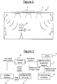
- Figure 1 illustrates an example of a lighting system installed or otherwise disposed in an environment 2 according to embodiments of the present disclosure.
- the environment 2 may comprise an indoor space comprising one or more rooms, corridors or halls, e.g. of a home, office, shop floor, mall, restaurant, bar, warehouse, airport, station or the like; or an outdoor space such as a garden, park, street, or stadium; or a covered space such as a gazebo, pagoda or marquee; or any other type of enclosed or partially enclosed space such as the interior of a vehicle.
- the environment 2 in question comprises an interior space of a building.
- the lighting system comprises one or more luminaires 4, each comprising one or more lamps plus any relevant fixture. Each lamp may be for example an LED-based lamp, a filament bulb or a fluorescent tube.
- the one or more luminaires 4 are controlled by a lighting control network 6.
- the lighting system also comprises a location system or network comprising one or more wireless anchor nodes 10.
- the anchor nodes 10 may also have an additional function such as being access points of a wireless local area network (WLAN), e.g. a Wi-Fi- network (and hence maybe "shared" components comprised by both the lighting system and another system such as a WLAN).
- the anchor nodes 10 may be dedicated nodes of the location system.
- a user 12 accompanying a wireless mobile user device 14, e.g. carrying the wireless device 14 about his or her person, or being situated in a position consistent with operating the device 14.
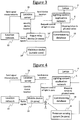
- FIG. 2 provides an overview of the system and shows the interaction of the wireless user device 14 with the location network 10 and the lighting control network 6.
- the lighting control network 6 may be coupled to a location server 16 for use in providing location services, as will be discussed in more detail shortly.
- the location server 16 may comprise one or more server units at one or more sites. This server 16 could be physically disposed in the environment 2 (e.g. coupled to the lighting network via a local wired or wireless network in the same building) or could be accessed remotely (e.g. coupled via a wider network such as the Internet).
- the lighting control network 6 may also be coupled to a commissioning database 18 storing a mapping between the luminaires 4 or lamps and physical (spatial) zones of the environment 2 (e.g. rooms of a building).
- the commissioning database 18 may also store calibration parameters and/or other settings for operating one or more of the lamps. Again, the commissioning database 18 could be physically disposed in the environment 2 (e.g. coupled to the lighting network 6 via a wired or wireless local network in the same building) or could be accessed remotely (e.g. via a wider network such as the Internet).
- the wireless user device 14 and lighting control network 6 are operable to communicate wirelessly with one another.
- the anchor nodes 10 are also wireless access points (access nodes) of a wireless local area network, e.g. Wi-Fi access points
- the lighting network 6 may be connected to the local network either directly by a wired or wireless local connection, or indirectly via wider network such as the Internet.
- the wireless user device 14 may then communicate with the lighting network 6 via the access/anchor nodes 10 and suitable wireless transceivers (not shown) in the device 14 and lighting network 6 respectively.
- wireless user device 14 and lighting control network 6 could be arranged to communicate via a separate channel than anchor/access nodes 10 of the location network, such as via separate dedicated RF transceivers in the device 14 and lighting network 6 respectively, or via a connection through the cellular network and Internet.
- the system is arranged to determine device location information relating to the location of the wireless user device 14, and to communicate that information to the lighting control network 6 via such channels as exemplified above.
- Device location information may comprise an indication of whether or not a wireless device 14 is found to be within a particular spatial region, i.e. its presence or absence, e.g. within a particular room.
- the device location information may comprise a position of the wireless device 14, i.e. information narrowing down the location of the device within the spatial region in question, beyond just an indication of whether or not present in that region, e.g. narrowing down to a particular place or point within a room or other region.
- the position may comprise spatial coordinates of the wireless device 14.
- the device location information may be determined by reference to the anchor nodes 10 of a location network, such as an indoor positioning system, based on one or more signals transmitted between the wireless user device 14 and one or more of the anchor nodes 10.
- the locations of the anchor nodes are known, e.g. being at fixed location, thus providing a known reference for determining the location of the wireless user device 14.
- the anchor locations may be stored in the location server 16.
- the device location information may comprise an indication of whether or not the wireless device 14 is found to be within wireless range of an anchor node 10, or within a distance-bounded range, thus indicating whether the device 14 is present in or absent from a region associated with the anchor node's range or distance-bounded range.
- the device location information may comprises a position determined based on measuring a property of the signal(s) transmitted between the device 14 and one or more anchor nodes 10, such as the RSSI (receiver signal strength indicator), ToA (time of arrival) and AoA (Angle of arrival) of the signal(s) between the wireless user device 14 and the one or more anchor nodes 10.
- the device's position could be estimated based on RSSI or ToA along with the AoA of a signal transmitted between the device 14 and one or more anchor nodes 10; or could be estimated based on the RSSI or ToA and a multilateration involving multiple anchor nodes, optionally also including AoA information.
- the location of the wireless device 14 maybe determined in a "device centric" fashion, i.e. the wireless user device 14 makes the measurement(s) of one or more signals received from one or more anchor devices 10, and performs the processing to determine its own location at the wireless device 14 itself based on such measurements.
- the wireless user device 14 can then submit the location information to the lighting control network 6.
- the wireless user device 14 may determine its location relative to one or more anchor nodes 10, and then look-up the location of the anchor node(s) 10 in the location database 16 to interpret that location in more absolute terms.
- this look-up may comprise mapping the anchor node 10 to an identification of a particular spatial region such as a particular room of a building, to thereby determine which room or region the wireless device 14 is found in.
- this look-up may comprise looking up the spatial coordinates of the node(s) 10 relative to a map, floor plan or the globe in order to combine these coordinates with the wireless user device's coordinates relative to the node(s) 10, thereby finding the coordinates of the wireless device 14 relative to the map, floor plan or the globe.
- the lighting control network 6 need not necessarily have its own connection to the location server 16 (though it may do). Instead the wireless user device 14 may be provided with a connection to the location server 16, e.g. via an access point 10 or other access channel, and via a local wired or wireless connection or network and/or a wider network such as the internet. Alternatively the wireless user device 14 may submit the "raw" signal measurements or information on its relative location to the location server, and the location server 16 performs the interpretation there and passes on the resulting location information to the lighting control network 6 via the lighting control network's connection with the location server 16. Alternatively the wireless user device 14 could submit the raw signal measurements or information on its relative location to the lighting control network 6, and the lighting control network 6 could then perform the look-up based on the lighting control network's connection with the location server 16.
- the location of the wireless device 14 maybe determined in a "network centric" fashion, i.e. one or more nodes 10 of the location network takes the measurement(s) of one or more signals received from the wireless user device 14, and the processing to determine the device's location based on such measurements is performed in the location network 10 or location server 16. Again this may involve a look-up in the location database 16 to interpret the relative location in more absolute terms, in a similar manner to that discussed above.
- the device positioning is not limited to a network of fixed anchor nodes 10.
- An alternative 10 would be to use a satellite based positioning system such as GPS, for determining the position of a wireless device 14 relative to a plurality of satellites.
- the lighting network 6 uses the device location information to determine whether or not the wireless mobile device 14 is found in a certain spatially-limited region associated with the lighting system.
- This region may for example be a particular zone of a building such as a particular room or an area within a room, or a zone of a covered or outdoor space.
- the region may comprise a region illuminated by the lighting system, or may be comprised by a region illuminated by the lighting system.
- the region could comprise a designated control zone outside the region being illuminated, e.g. a supervisor's office.
- the region in question may be a single region associated with the whole lighting system; or the lighting system could have multiple distinct regions associated with it, each served by different lighting in the form of one or more respective luminaires 4 or lamps of the lighting system (e.g. different rooms or other zones being served by different lights).
- the lighting control system 6 may determine whether the wireless user device 14 is found in a particular zone associated with particular lighting, and if so which region and which lighting this corresponds to. This may be performed by reference to locations or positions in commissioning database 18.
- the lighting control system 6 is configured to grant the wireless user device 14 with access to control of the lighting system on condition that it finds the wireless user device 14 to be in the appropriate spatial region.
- the wireless user device 14 may be granted access to control of the particular luminaire(s) 4 or lamp(s) illuminating a particular area (e.g. particular room) on condition of finding that wireless device 14 to be within the respective illuminated area or possibly another authorized zone associated with the illuminated area (e.g. a supervisor's office).
- the lighting control system 6 may be configured to perform this determination and conditionally grant control in response to a request issued from the wireless user device 14 to the lighting control system 6 (e.g. via any of the communication example channels discussed above).
- the lighting control system may poll the region or zone at intervals and grant the access automatically upon detecting a compatible user device 14.
- the wireless user device is granted access on condition of being found in a certain spatial region or the like, this does not necessarily preclude there being one or more additional access rules which may comprise other conditions that must be fulfilled as well.
- the one or more additional access rules may comprise a condition that the identity of the wireless device must be authenticated.
- the access rules may comprise one or more additional rules that are specifically applicable to the spatial region in question, such as an additional condition that the wireless device must be verified as having an administrator status for that spatial region.
- the control may comprise one or more of a number of potential functions.
- the control may comprise manual control of the relevant lighting 4 by the user 12 via a user interface of the wireless user device 14.
- the control may comprise turning the relevant lighting 4 on or off, or dimming the lighting, and/or may comprise commissioning functions.
- the control may comprise storing lighting settings in a luminaire 4 or the commissioning database 18, and/or may comprise reading settings or a status report from a luminaire 4 or the commissioning database 18 (which readings may be communicated back to the device 14 via any suitable channel such as those discussed above).
- a luminaire 4 comprises more than one lamp
- the control may enable control of individual lamps or may be limited to controlling the luminaire 4 as a whole. Alternatively there may be just one lamp per luminaire 4.
- the nodes 10 of the location network take the signal measurements of signals received from the wireless device 14, and send these measurements to the location server 16 for interpretation to identify the device location.
- the wireless user device 14 requests access to control of the lighting from the lighting control network 6.
- the lighting control network 6 retrieves the location information from the location server 16 and determines whether the wireless device 14 is found to be within the valid control zone, e.g. within the room whose lighting is sought to be controlled. Optionally this may be performed with reference to a mapping of zones to lighting stored in the commissioning database 18. If the wireless device 14 is found to be within the valid control region (and fulfills any other access rules applicable for that spatial region), the lighting control network 6 grants access but if not it withholds granting the access.
- the lighting control network 6 then controls the relevant lighting 4 based on one or more control signals received from the wireless user device (which again may be communicated via any suitable channel such as those discussed above), and optionally 4 based on settings or other parameters retrieved the commissioning database 18.
- the wireless user device which again may be communicated via any suitable channel such as those discussed above
- the commissioning database 18 optionally 4 based on settings or other parameters retrieved the commissioning database 18.
- Figure 3 illustrates a security threat in the provision of access rights to a user based on the location of a wireless device 14.
- the components and functionality of the system are the same as Figure 2 .
- a malicious user may separate the positioning functionality of the user device from the controlling functionality. This is done by leaving a rogue relay device 14' in the control zone (e.g. room) that acts as the identified wireless device (based on location), but another user device 14" of the malicious user seeking control is actually placed at a different location outside the valid control zone (e.g. outside the relevant room).
- the malicious user device 14" then can control the lights by assuming the identity of the relay device 14' or remotely controlling the relay device 14' in the room or zone.
- a malicious party may introduce malicious software into the located device 14' in the room or zone, which then sends out control commands (pre-programmed by the malicious user) to disrupt lighting behavior.
- the following discloses a selection of exemplary embodiments for more secure provision of control access based on location information.
- Each of these embodiments is based on a principle of determining whether a user (a human) is, or is likely to be, accompanying a wireless device 14 or 14' in the control zone. If so, access to control of the lighting 4 may be granted, but if not the grant of access is withheld.
- the disclosed techniques may be applicable to any system where access is provided to a user based on location of a wireless device, e.g. in application segments like offices, retail, industry, hospitality, and outdoor.
- a presence sensing system 8 is used to validate requests from a user to access the lighting control network.
- the presence sensing system determines binary (yes/no) occupancy of a user in the zone from which a location-based access request is received.
- a localized presence sensing system determines a particular position of a user in the vicinity of the position from which a location-based access request is received.
- a challenge is issued into the control zone, which a human must respond to by performing a physical act to prove him or herself to be present, and which can be observed and validated by a trusted system.
- the access provided to a device 14 is time-limited, on the basis that if a device 14' has remained too long in the control zone (e.g. overnight or for more than a time limit such as 24 hours) then it is unlikely to be accompanied by a user.
- anomaly detection is used to recognize the non-existence of a user in a zone.
- any of these embodiments for determining whether the wireless device 14 or 14' is unaccompanied by a user may be applied alone or in conjunction.
- the access may only be granted on meeting a combination of the tests of two or more of the embodiments, or may be granted in response to meeting any one or a subset of such tests.
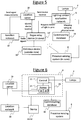
- Figures 4 to 6 illustrate an example environment 2 and lighting control system in accordance a first embodiment disclosed herein.
- Figure 4 illustrates the scenario (somewhat analogous to Figure 2 ) where a legitimate wireless user device 14 is accompanied by a user 12, e.g. carrying the wireless device 14 about his or her person, or being situated in a position consistent with operating the device 14.
- Figure 5 illustrates the scenario (somewhat analogous to Figure 3 ) where a rogue device such as a rogue relay device 14' is left in the control zone unaccompanied by a user, e.g. with a malicious user controlling the relay device 14' remotely from a malicious device 14" outside the zone.
- Figure 6 expands on more detail of the lighting control network 6 according to embodiments disclosed herein.
- the lighting control system is coupled to a presence sensing system 8 comprising one or more presence sensors.
- Lighting systems may already comprise presence sensors for automatically turning on and off or dimming lighting in dependence on whether a user is present.
- presence sensing has not previously been applied for determining whether access to control of the lighting should be granted to a wireless user device 14. According to the disclosure herein, this provides one way of determining whether a wireless device 14 or 14' is accompanied by a user and therefore whether it should be granted access or whether it is likely to be a rogue device such as a relay device.
- the lighting control network 6 comprises a controller 20.
- the controller 20 may be implemented in software stored on a computer-readable storage medium such as a magnetic or electronic medium, and arranged to be executed on a processor comprising one or more processing units. Alternatively it is not excluded that the controller 20 may be implemented wholly or partially in dedicated hardware circuitry, or configurable or re-configurable hardware circuitry such as a PGA or FPGA.
- the controller 20 may be a central controller arranged to control lighting 4 in a plurality of different places such as different rooms of a building, the control in each being based on detecting location in a respective control zone.
- the controller 20 may just serve the lighting associated with an individual control zone.
- the lighting system covers multiple such zones each associated with a respective portion of the lighting 4 comprising a respective one or more luminaires 4 or lamps.
- access to control of the lighting system may be granted only for the purpose of controlling the lighting associated with the respective zone - e.g. control of the lighting system is granted just for the control of lighting in the room from which the request for control is submitted. Granting access to "control of the lighting system" or the like does not necessarily imply control of the whole system or of all possible functionality.
- the controller 20 comprises an access module 24, and a control module 22 configured to operate the lighting 4 in accordance with control signals from the wireless user device 14 on condition of access being granted by the access module 24 based on preconfigured access rules.
- the access module 24 comprises a device location module 26 and a user location module 28.
- the device location module 26 is configured to determine the device location information relating to a location of the wireless device 14, as discussed above in relation to Figures 1 and 2 .
- the access rules applied by the access module 24 comprise a condition that the wireless device 14, 14' is within the corresponding control region or zone, as discussed above.
- the user location module 28 is configured to determine user location information relating to a location of a user 12.
- the user location information may comprise an indication as to whether or not any person is found to be present in the control zone, i.e. whether the zone is occupied or unoccupied, or an indication that the zone is likely to be unoccupied, or an indication that the zone is likely to be occupied.
- the user location information may comprise a position of a user, i.e. information narrowing down the location of a user 12 within the spatial region in question, beyond just an indication of whether or not present in that region, e.g. narrowing down to a particular place or point within a room or other zone.
- the position may comprise spatial coordinates of the user 12.
- the access module 24 uses such information to determine whether a wireless device 14 or 14' found within the control zone is also accompanied by a user 12 (a human). On condition that a wireless device 14 is found within the valid control zone and fulfills any other access rules applicable for that spatial region, and on condition that the wireless device is determined to be accompanied, then the access module 24 grants the wireless user device 14 with access to the relevant control of the lighting system 6, 4 via the control module 22. If either condition is not met on the other hand, the access module 22 withholds this granting of access - either by actively blocking access or by refraining from issuing a security token that grants the access. Note also that this function of the access module is not trying to verify the identity of a particular user or that a particular individual user is authorized. Rather, it is verifying whether the device 14 or 14' is accompanied by any human, as opposed to being unaccompanied in that it has been left behind by a malicious user who is not present.
- the access module 24 uses an input from a presence sensing system 8 to determine whether a wireless device 14 or 14' is accompanied by a user.
- a presence sensing system 8 that is typically already part of a lighting system can be used for an additional purpose to detect and prevent the security threat discussed above.
- the presence sensing system 8 comprises a binary (yes/no) occupancy sensor.
- Binary occupancy sensors such as those based on PIR (passive infrared) or ultrasound are typically used in many existing lighting systems for presence detection.
- the occupancy sensor indicates presence or absence (of some user) within its detection region. This region may be defined by the sensor's range or by distance bounding (e.g. based on signal strength or time-of flight of an ultrasound pulse).
- the occupancy sensor may additionally be used to detect the security threat in the case that a rogue device 14' is in the room or control zone, but the malicious user is outside the room or zone, since in this case no occupancy is detected.
- the access module 24 makes a query to the occupancy sensing system 8. Only if occupancy is determined, control access is provided to the requesting user device 14.
- a localizing presence sensing system 8 comprising localizing presence sensors is used to counter the security threat.
- the location network provides the position coordinates to the access module 24 for comparison with information on the user 12 from the localizing presence sensing system 8. This information may comprise a position of the user, e.g. in terms of spatial coordinates 12.
- the access module 24 can check whether a user 12 is found at the same position as the module device 14 requesting access. Note that "same position" or the like does not require the device 14 to be within a user's body - the user 12 and device 14 may be considered to be at the same location if their relative positions are consistent with the user carrying or using the user device 14.
- the presence sensing system 8 may be used to check whether there is user movement, either in the control zone generally or specifically at the position of the device 14. If a user movement is determined, then control access is provided to the requesting user device 14 at that position; if not, control access is denied.
- the access module 24 is configured to issue a challenge into the relevant region or zone, challenging a user to prove human presence.
- the challenge is issued only into the valid control zone exclusive of anywhere outside that zone, or at least selectively into that region in discrimination of regions outside. Further, the challenge can only be understood and/or responded to by a human user and cannot be simulated by a rogue device 14'.
- the challenge may be of a form that a device 14' cannot interpret automatically.
- the challenge may comprise an audio message played out into the zone (e.g. room), only being substantially audible within that zone or room.
- the challenge may comprise a human readable image such as text displayed on a screen in the room or zone, not visible outside.
- an audible message or human-readable image sent from the lighting system 6 to the wireless device 14 (via any suitable channel such as those discussed above) to be played out or displayed via the wireless device 14, e.g. text styled to resist automatic recognition such as the style used to distinguish internet bots from humans remotely on the internet.
- the user 12 is thus challenged to perform a physical action in response via the controlling device 14.
- the action in response to the challenge may comprise repeating the challenge verbatim, or performing some other correct action instructed by the challenge or otherwise derived by a human from the challenge.
- the action may be pre-defined for all users and locations, or a pre-defined action for different users or for different locations.
- the action could be independent of user or location but randomly chosen by the user location module and informed to the user through the wireless user device 14. This action has to be performed for the user location module to receive the response that is expected.
- the action may be a physical action that cannot be performed automatically by a wireless device 14'.
- Such physical actions may comprise moving the mobile in three-dimensional space or pressing a button sequence on one or more trusted devices (like a beamer) in the room.
- the response may be submitted back through a signal from the wireless user device 14 (via any suitable channel such as those discussed above), or through a separate user interface installed in the room or zone such as a console or speech recognition system.
- a third embodiment is based on time limited access being granted to the device 14 or 14'.
- the user location module comprises a timer and an input for receiving information on when the wireless device 14 or 14' has been found within the room or control zone.
- the wireless device 14 or 14' is allowed to control the room only for a specified duration after it has been detected to have entered the relevant zone. Further, the wireless device 14 may be required to prove that it entered the region or left it at least once per specified time interval. This prevents a relay device 14' being left behind, that could otherwise control the lighting system for unlimited time. If a device 14 remains in the same zone or same position for longer than a threshold point in time or time period, this may be taken as indicative of the fact that it is unlikely to be accompanied by a user. Example thresholds would be 12 hours, 18 hours, 24 hours, 36 hours, 48 hours, or overnight.
- the user location system may track the device 14 as it moves from or towards any of the known entrances of the room.
- a fourth embodiment is based on anomaly detection techniques.
- the user location module of the lighting control system 6 performs additional checks based on pre-defined rules or from learning normal operational behavior from the past. If it detects anomalous behavior not consistent with the way a legitimate user present in the room or zone would likely use the lighting system, this may be taken as indicative of the fact that the wireless device 14' signaling the control is unlikely to be that of a legitimate user present in the room or zone. Examples of such rules may comprise disallowing access if a device 14' attempts to completely switch off the lights when presence of users in the room is known to the lighting system, and/or disallowing access in response if a device 14' attempts to switch lights on and off or vary the dimming of lights back and forth at greater than a threshold rate. Additional information on the status or use of other equipment (like a beamer) could be used to identify anomaly in the commands sent to the lighting system.
Claims (15)
- Appareil à utiliser dans un système d'éclairage, l'appareil comprenant :un module de localisation de dispositif (26) configuré pour déterminer des informations de localisation de dispositif se rapportant à une localisation d'un dispositif utilisateur sans fil (14, 14') à l'intérieur d'une région spatiale associée au système d'éclairage ; etun module de localisation utilisateur (28) configuré pour déterminer des informations de localisation d'utilisateur indicatives du fait qu'un utilisateur (12) accompagne ou non le dispositif utilisateur sans fil dans ladite région spatiale ; et caractérisé en ce que l'appareil comprend en outre :
un module d'accès (24) configuré pour permettre au dispositif utilisateur sans fil (14, 14') de commander le système d'éclairage en fonction d'une pluralité de règles d'accès, les règles d'accès comprenant au moins que : (i) une admission est conditionnelle sur le dispositif utilisateur sans fil déterminé, sur la base d'informations de localisation dudit dispositif, comme étant à l'intérieur de ladite région spatiale associée au système d'éclairage, et (ii) ladite admission est refusée en réponse à la détermination que lesdites informations de localisation d'utilisateur sont indicatives du dispositif utilisateur sans fil qui est non accompagné par un utilisateur (12). - Appareil selon la revendication 1, dans lequel le module de localisation utilisateur (28) est configuré pour déterminer lesdites informations de localisation d'utilisateur sur la base d'une entrée provenant d'au moins un capteur de présence (8).
- Appareil selon la revendication 2, dans lequel l'au moins un capteur de présence (8) est un capteur d'occupation et lesdites informations de localisation d'utilisateur indiquent si n'importe quel utilisateur (12) est situé dans ladite région, et dans lequel ladite détermination que le dispositif utilisateur sans fil (14') est non accompagné comprend la détection qu'aucun utilisateur n'est présent dans ladite région.
- Appareil selon la revendication 1, dans lequel le module de localisation utilisateur (28) est configuré pour déterminer lesdites informations de localisation d'utilisateur sur la base d'au moins :une entrée en provenance d'au moins un capteur de présence sous la forme d'un capteur de position ;une entrée en provenance d'au moins un capteur de présence sous la forme d'un capteur de mouvement ; ouun temps pendant lequel le dispositif utilisateur sans fil (14, 14') est resté dans ladite région.
- Appareil selon la revendication 2, dans lequel l'au moins un capteur de présence (8) est un capteur de position et lesdites informations de localisation d'utilisateur comprennent une position d'un utilisateur (12) à l'intérieur de ladite région, dans lequel les informations de localisation de dispositif comprennent une position du dispositif utilisateur sans fil (14, 14') à l'intérieur de ladite région, et dans lequel ladite détermination que le dispositif utilisateur sans fil est non accompagné comprend la détection que l'utilisateur n'est pas situé à une même position à l'intérieur de ladite région que le dispositif utilisateur sans fil.
- Appareil selon l'une quelconque des revendications 2, 3 ou 5, dans lequel le capteur de présence (8) comprend un capteur de mouvement et lesdites informations de localisation d'utilisateur indiquent si vraiment un mouvement est détecté dans ladite région, et dans lequel ladite détermination que le dispositif utilisateur sans fil (14') est non accompagné comprend la détection de l'absence de mouvement dans ladite région.
- Appareil selon l'une quelconque des revendications précédentes, dans lequel :le module d'accès (24) est configuré pour lancer une demande d'accès dans la région associée au système d'éclairage ;lesdites informations de localisation d'utilisateur comprennent un retour d'une réponse à ladite demande d'accès démontrant qu'un utilisateur (12) est présent dans ladite région, ou une absence de la réponse indiquant qu'un utilisateur n'est pas présent, la demande d'accès étant compréhensible pour un utilisateur, mais pas reconnue automatiquement par le dispositif utilisateur sans fil (14, 14') et/ou la réponse comprenant une action physique qui n'est pas automatiquement effectuée par le dispositif utilisateur sans fil ; etdans lequel ladite détermination que le dispositif utilisateur sans fil est non accompagné comprend la détection de l'absence de ladite réponse.
- Appareil selon l'une quelconque des revendications précédentes, dans lequel le module de localisation utilisateur (28) comprend une minuterie et une entrée en provenance du module de localisation de dispositif (26), dans lequel les informations de localisation d'utilisateur comprennent un temps pendant lequel le dispositif utilisateur sans fil (14, 14') est resté dans ladite région, et dans lequel ladite détermination que le dispositif utilisateur sans fil est non accompagné comprend la détermination que le dispositif utilisateur sans fil est resté dans la région au-delà d'une durée de sorte qu'un utilisateur (12) est supposé ne pas accompagner le dispositif utilisateur sans fil.
- Appareil selon l'une quelconque des revendications précédentes, dans lequel les informations de localisation d'utilisateur comprennent des informations concernant un comportement anormal non compatible avec un utilisateur (12) situé à l'intérieur de ladite région, et dans lequel ladite détermination que le dispositif utilisateur sans fil (14') est non accompagné comprend la détection du comportement anormal.
- Appareil selon l'une quelconque des revendications précédentes, dans lequel ladite région spatiale comprend une région illuminée par le système d'éclairage, ou est comprise par une région illuminée par le système d'éclairage.
- Appareil selon l'une quelconque des revendications précédentes, dans lequel le module de localisation de dispositif est configuré pour déterminer les informations de localisation de dispositif à partir d'un ou de plusieurs noeuds d'ancrage fixés (10) d'un réseau de localisation.
- Appareil selon l'une quelconque des revendications précédentes, dans lequel le module de localisation de dispositif (26) est configuré pour déterminer les informations de localisation de dispositif à partir d'un système de positionnement d'intérieur.
- Unité de commande (20) comprenant l'appareil selon l'une quelconque des revendications 1 à 12, et un module de commande (22) configuré pour mettre en oeuvre un ou plusieurs luminaires (4) du système d'éclairage sur la base de signaux de commande en provenance du dispositif utilisateur sans fil (14) quand le module d'accès (24) permet au dispositif utilisateur sans fil de commander le système d'éclairage.
- Système d'éclairage comprenant :un ou plusieurs luminaires (4) ;un module de commande (22) pour commander le système d'éclairage en mettant en oeuvre le ou les plusieurs luminaires ;un module de localisation de dispositif (26) configuré pour déterminer une localisation de dispositif se rapportant à une localisation d'un dispositif utilisateur sans fil (14, 14') à l'intérieur d'une région spatiale associée au système d'éclairage ;un module de localisation utilisateur (28) configuré pour déterminer des informations de localisation d'utilisateur indicatives de si un utilisateur (12) accompagne le dispositif utilisateur sans fil dans la région spatiale ; caractérisé en ce que le système d'éclairage comprend en outre :
un module d'accès (24) configuré pour permettre au dispositif utilisateur sans fil (14, 14') de commander le système d'éclairage en fonction d'une pluralité de règles d'accès, les règles d'accès comprenant au moins que : (i) une admission est conditionnelle sur le dispositif utilisateur sans fil déterminé, sur la base desdites informations de localisation de dispositif, comme étant à l'intérieur de ladite région spatiale associée au système d'éclairage, et (ii) ladite admission est refusée en réponse à la détermination que lesdites informations de localisation d'utilisateur sont indicatives du dispositif utilisateur sans fil étant non accompagné par un utilisateur (12). - Produit formant programme informatique pour sécuriser la commande d'un système d'éclairage, le produit formant programme informatique comprenant un code réalisé sur un support de stockage lisible par ordinateur et configuré de façon à, lorsqu'il est exécuté par un processeur, effectuer les opérations de :détermination de localisation de dispositif se rapportant à une localisation d'un dispositif utilisateur sans fil (14, 14') à l'intérieur d'une région spatiale associée au système d'éclairage ;détermination d'informations de localisation d'utilisateur indicatives de si un utilisateur (12) accompagne le dispositif utilisateur sans fil dans ladite région spatiale ; et caractérisé en ce que le code est en outre configuré pour effectuer une opération de :
autorisation au dispositif utilisateur sans fil (14, 14') à commander le système d'éclairage en fonction d'une pluralité de règles d'accès, les règles d'accès comprenant au moins que : (i) une admission est conditionnelle sur le dispositif utilisateur sans fil déterminé, sur la base desdites informations de localisation de dispositif, comme étant à l'intérieur de ladite région spatiale associée au système d'éclairage, et (ii) ladite admission est refusée en réponse à la détermination que lesdites informations de localisation d'utilisateur sont indicatives du dispositif utilisateur sans fil étant non accompagné par un utilisateur (12).
Priority Applications (1)
| Application Number | Priority Date | Filing Date | Title |
|---|---|---|---|
| EP14759321.4A EP3036975B1 (fr) | 2013-08-23 | 2014-07-23 | Commande d'un système d'éclairage |
Applications Claiming Priority (3)
| Application Number | Priority Date | Filing Date | Title |
|---|---|---|---|
| EP13181579 | 2013-08-23 | ||
| PCT/IB2014/063340 WO2015025235A1 (fr) | 2013-08-23 | 2014-07-23 | Commande d'un système d'éclairage |
| EP14759321.4A EP3036975B1 (fr) | 2013-08-23 | 2014-07-23 | Commande d'un système d'éclairage |
Publications (2)
| Publication Number | Publication Date |
|---|---|
| EP3036975A1 EP3036975A1 (fr) | 2016-06-29 |
| EP3036975B1 true EP3036975B1 (fr) | 2019-05-15 |
Family
ID=49028988
Family Applications (1)
| Application Number | Title | Priority Date | Filing Date |
|---|---|---|---|
| EP14759321.4A Not-in-force EP3036975B1 (fr) | 2013-08-23 | 2014-07-23 | Commande d'un système d'éclairage |
Country Status (6)
| Country | Link |
|---|---|
| US (1) | US9961747B2 (fr) |
| EP (1) | EP3036975B1 (fr) |
| JP (1) | JP6456387B2 (fr) |
| CN (1) | CN105684556B (fr) |
| RU (1) | RU2678690C2 (fr) |
| WO (1) | WO2015025235A1 (fr) |
Families Citing this family (25)
| Publication number | Priority date | Publication date | Assignee | Title |
|---|---|---|---|---|
| US10021767B2 (en) | 2014-04-25 | 2018-07-10 | Philips Lighting Holding B.V. | Zone based lighting access |
| WO2015189161A1 (fr) | 2014-06-13 | 2015-12-17 | Koninklijke Philips N.V. | Localisation basée sur un réseau de nœuds sans fil |
| US10623950B2 (en) | 2015-06-23 | 2020-04-14 | Signify Holding B.V. | System for protecting location information |
| JP6540283B2 (ja) * | 2015-06-30 | 2019-07-10 | 富士通株式会社 | 通信装置、通信方法、および、通信プログラム |
| GB2531865B (en) * | 2015-07-31 | 2019-12-25 | Legrand Electric Ltd | Electronic device connection method |
| JP6517623B2 (ja) * | 2015-08-04 | 2019-05-22 | 株式会社東芝 | 無線機器配置推定装置、無線機器配置推定方法、無線機器配置推定プログラム |
| WO2017024275A2 (fr) | 2015-08-05 | 2017-02-09 | Lutron Electronics Co., Inc. | Système de commande de charge sensible à l'emplacement d'un occupant et/ou dispositif mobile |
| EP3348007A1 (fr) | 2015-09-07 | 2018-07-18 | Philips Lighting Holding B.V. | Incorporation de données dans la lumière |
| DE102015222471A1 (de) | 2015-11-13 | 2017-05-18 | Osram Gmbh | System und Verfahren zur Positionsermittlung einer mobilen Bake |
| CN106879099A (zh) * | 2015-12-10 | 2017-06-20 | 亿光电子工业股份有限公司 | 照明装置 |
| WO2017144408A1 (fr) | 2016-02-25 | 2017-08-31 | Philips Lighting Holding B.V. | Dispositifs appariés |
| WO2017162550A1 (fr) * | 2016-03-24 | 2017-09-28 | Philips Lighting Holding B.V. | Commande d'éclairage utilisant une distribution spatiale d'utilisateurs |
| US10379514B2 (en) * | 2016-07-27 | 2019-08-13 | Ademco Inc. | Systems and methods for controlling a home automation system based on identifying a user location via a wi-fi fingerprint |
| CN109792821B (zh) * | 2016-08-10 | 2021-12-07 | 昕诺飞控股有限公司 | 照明控制 |
| US10129964B1 (en) * | 2016-10-19 | 2018-11-13 | City Theatrical, Inc. | Wireless tool and methods for controlling and testing systems |
| KR20180062036A (ko) | 2016-11-30 | 2018-06-08 | 삼성전자주식회사 | 조명 제어장치 및 방법 |
| CN107277968B (zh) * | 2017-06-07 | 2019-11-08 | 安徽艳阳电气集团有限公司 | 一种小区楼宇led灯智能控制平台 |
| US10652249B2 (en) * | 2017-10-31 | 2020-05-12 | Microsoft Technology Licensing, Llc | Remote locking a multi-user device to a set of users |
| JP6988020B2 (ja) * | 2018-07-26 | 2022-01-05 | シグニファイ ホールディング ビー ヴィSignify Holding B.V. | トラッキングシステムをコンフィギュレーションするための方法、トラッキングシステム、トラッキングシステムを組み込んだ照明システム及びコンピュータプログラム |
| US20220014244A1 (en) * | 2018-11-30 | 2022-01-13 | Telefonaktiebolaget Lm Ericsson (Publ) | Methods for providing lower-layer split full spatial samples |
| US11232684B2 (en) | 2019-09-09 | 2022-01-25 | Appleton Grp Llc | Smart luminaire group control using intragroup communication |
| US11219112B2 (en) | 2019-09-09 | 2022-01-04 | Appleton Grp Llc | Connected controls infrastructure |
| US11343898B2 (en) | 2019-09-20 | 2022-05-24 | Appleton Grp Llc | Smart dimming and sensor failure detection as part of built in daylight harvesting inside the luminaire |
| US10789846B1 (en) * | 2020-03-19 | 2020-09-29 | Cdw Llc | Available vehicle parking space dispatch |
| WO2022043008A1 (fr) * | 2020-08-26 | 2022-03-03 | Signify Holding B.V. | Système d'identification et de localisation individuel basé sur la reconnaissance d'image |
Citations (1)
| Publication number | Priority date | Publication date | Assignee | Title |
|---|---|---|---|---|
| US20120184299A1 (en) * | 2009-06-30 | 2012-07-19 | Koninklijke Philips Electronics N.V. | Systems and methods for managing interaction with controllable lighting networks |
Family Cites Families (34)
| Publication number | Priority date | Publication date | Assignee | Title |
|---|---|---|---|---|
| US5489827A (en) * | 1994-05-06 | 1996-02-06 | Philips Electronics North America Corporation | Light controller with occupancy sensor |
| US5721583A (en) * | 1995-11-27 | 1998-02-24 | Matsushita Electric Industrial Co., Ltd. | Interactive television system for implementing electronic polling or providing user-requested services based on identification of users or of remote control apparatuses which are employed by respective users to communicate with the system |
| US5905442A (en) * | 1996-02-07 | 1999-05-18 | Lutron Electronics Co., Inc. | Method and apparatus for controlling and determining the status of electrical devices from remote locations |
| US20020043938A1 (en) * | 2000-08-07 | 2002-04-18 | Lys Ihor A. | Automatic configuration systems and methods for lighting and other applications |
| US6720874B2 (en) * | 2000-09-29 | 2004-04-13 | Ids Systems, Inc. | Portal intrusion detection apparatus and method |
| DE60330018D1 (de) * | 2002-09-04 | 2009-12-24 | Koninkl Philips Electronics Nv | Master-slave-orientiertes zweiseitiges drahtloses hf-beleuchtungssteuersystem |
| US20050239445A1 (en) * | 2004-04-16 | 2005-10-27 | Jeyhan Karaoguz | Method and system for providing registration, authentication and access via broadband access gateway |
| US7286835B1 (en) | 2004-09-10 | 2007-10-23 | Airespace, Inc. | Enhanced wireless node location using differential signal strength metric |
| US8093817B2 (en) * | 2005-04-22 | 2012-01-10 | Koninklijke Philips Electronics N.V. | Method and system for lighting control |
| EP1882393A1 (fr) * | 2005-04-22 | 2008-01-30 | Koninklijke Philips Electronics N.V. | Procede et systeme de commande d'eclairage |
| US8880047B2 (en) * | 2005-08-03 | 2014-11-04 | Jeffrey C. Konicek | Realtime, location-based cell phone enhancements, uses, and applications |
| WO2008059412A1 (fr) * | 2006-11-17 | 2008-05-22 | Philips Intellectual Property & Standards Gmbh | Dispositif d'éclairage pour planchers |
| EP2084944B1 (fr) * | 2006-11-17 | 2012-05-30 | Koninklijke Philips Electronics N.V. | Bâton lumineux pour une commande d'éclairage |
| EP2158499A1 (fr) * | 2007-06-14 | 2010-03-03 | Koninklijke Philips Electronics N.V. | Procédé de localisation d'objet, système, marqueur et dispositif d'interface utilisateur |
| US7852205B2 (en) | 2008-04-10 | 2010-12-14 | Honeywell International Inc. | System and method for calibration of radio frequency location sensors |
| BRPI0918937A2 (pt) | 2009-01-07 | 2016-10-11 | Koninkl Philips Electronics Nv | sistema de gerenciamento de iluminação, método para implementar o sistema de gerenciamento de iluminação e módulo executivo para o uso em um sistema de gerenciamento de iluminação |
| WO2010092510A1 (fr) | 2009-02-10 | 2010-08-19 | Philips Intellectual Property & Standards Gmbh | Systeme et procede de commande d'acces a un system de commande en reseau |
| JP2011009066A (ja) * | 2009-06-25 | 2011-01-13 | Panasonic Electric Works Co Ltd | 照明システム |
| US8581707B2 (en) | 2009-12-16 | 2013-11-12 | Pyramid Meriden Inc. | Methods and apparatus for identifying and categorizing distributed devices |
| US8959621B2 (en) * | 2009-12-22 | 2015-02-17 | Disney Enterprises, Inc. | Human verification by contextually iconic visual public turing test |
| WO2011151796A1 (fr) | 2010-06-03 | 2011-12-08 | Koninklijke Philips Electronics N.V. | Système et procédé permettant de commander l'éclairage |
| US8706310B2 (en) * | 2010-06-15 | 2014-04-22 | Redwood Systems, Inc. | Goal-based control of lighting |
| JP2011102792A (ja) * | 2010-09-28 | 2011-05-26 | Seiko Epson Corp | 測位装置及び測位方法 |
| WO2012085794A1 (fr) | 2010-12-22 | 2012-06-28 | Koninklijke Philips Electronics N.V. | Commande de systèmes immotiques |
| ES2539706T3 (es) | 2010-12-30 | 2015-07-03 | Koninklijke Philips N.V. | Un sistema de iluminación, una fuente luminosa, un dispositivo y un procedimiento de autorización del dispositivo por la fuente luminosa |
| US9198264B2 (en) * | 2010-12-30 | 2015-11-24 | Koninklijke Philips N.V. | Policy-based OLN light management system |
| JP2012155975A (ja) * | 2011-01-25 | 2012-08-16 | Iris Ohyama Inc | 人感センサ付照明器具 |
| US20130127591A1 (en) | 2011-11-20 | 2013-05-23 | International Business Machines Corporation | Secure facilities access |
| JP5578629B2 (ja) * | 2011-12-27 | 2014-08-27 | Necソリューションイノベータ株式会社 | 勤怠管理装置、勤怠管理方法およびプログラム |
| CN102843830A (zh) * | 2012-08-21 | 2012-12-26 | 常熟卓辉光电科技有限公司 | 一种基于物联网技术的无线智能照明控制装置 |
| RU2656686C2 (ru) | 2012-10-17 | 2018-06-06 | Филипс Лайтинг Холдинг Б.В. | Предоставление управления над совместно используемой системой |
| JP6072933B2 (ja) * | 2012-12-18 | 2017-02-01 | フィリップス ライティング ホールディング ビー ヴィ | センサからのパルスの送信の制御 |
| TWI508627B (zh) * | 2013-03-22 | 2015-11-11 | Internat Mobile Iot Corp | 照明控制系統 |
| CN106134269B (zh) * | 2014-01-07 | 2020-03-17 | 飞利浦灯具控股公司 | 控制定位系统中的信标 |
-
2014
- 2014-07-23 RU RU2016110422A patent/RU2678690C2/ru active
- 2014-07-23 EP EP14759321.4A patent/EP3036975B1/fr not_active Not-in-force
- 2014-07-23 WO PCT/IB2014/063340 patent/WO2015025235A1/fr active Application Filing
- 2014-07-23 US US14/913,778 patent/US9961747B2/en not_active Expired - Fee Related
- 2014-07-23 JP JP2016535542A patent/JP6456387B2/ja not_active Expired - Fee Related
- 2014-07-23 CN CN201480046704.0A patent/CN105684556B/zh not_active Expired - Fee Related
Patent Citations (1)
| Publication number | Priority date | Publication date | Assignee | Title |
|---|---|---|---|---|
| US20120184299A1 (en) * | 2009-06-30 | 2012-07-19 | Koninklijke Philips Electronics N.V. | Systems and methods for managing interaction with controllable lighting networks |
Also Published As
| Publication number | Publication date |
|---|---|
| JP2016530685A (ja) | 2016-09-29 |
| EP3036975A1 (fr) | 2016-06-29 |
| WO2015025235A1 (fr) | 2015-02-26 |
| RU2678690C2 (ru) | 2019-01-31 |
| US9961747B2 (en) | 2018-05-01 |
| CN105684556A (zh) | 2016-06-15 |
| CN105684556B (zh) | 2018-12-25 |
| US20160205746A1 (en) | 2016-07-14 |
| RU2016110422A3 (fr) | 2018-07-03 |
| JP6456387B2 (ja) | 2019-01-23 |
| RU2016110422A (ru) | 2017-09-28 |
Similar Documents
| Publication | Publication Date | Title |
|---|---|---|
| EP3036975B1 (fr) | Commande d'un système d'éclairage | |
| US10117308B2 (en) | Associating information with an asset or a physical space | |
| US10467887B2 (en) | Systems and methods of integrating sensor output of a mobile device with a security system | |
| US11595777B2 (en) | Electronic location identification and tracking system with beacon clustering | |
| CN106537963B (zh) | 基于无线节点的网络进行的定位 | |
| CN107258087B (zh) | 位置化信标信号和控制相关信号的时间复用传输 | |
| CA3027015C (fr) | Association d'informations a un actif ou a un espace physique | |
| US20210082216A1 (en) | Electronic access control and location tracking system | |
| US20180066861A1 (en) | Systems and methods of detection with active infrared sensors | |
| US11361060B1 (en) | Home automation system supporting dual-authentication | |
| US11949683B2 (en) | Guest access to control devices |
Legal Events
| Date | Code | Title | Description |
|---|---|---|---|
| PUAI | Public reference made under article 153(3) epc to a published international application that has entered the european phase |
Free format text: ORIGINAL CODE: 0009012 |
|
| 17P | Request for examination filed |
Effective date: 20160323 |
|
| AK | Designated contracting states |
Kind code of ref document: A1 Designated state(s): AL AT BE BG CH CY CZ DE DK EE ES FI FR GB GR HR HU IE IS IT LI LT LU LV MC MK MT NL NO PL PT RO RS SE SI SK SM TR |
|
| AX | Request for extension of the european patent |
Extension state: BA ME |
|
| DAX | Request for extension of the european patent (deleted) | ||
| STAA | Information on the status of an ep patent application or granted ep patent |
Free format text: STATUS: EXAMINATION IS IN PROGRESS |
|
| 17Q | First examination report despatched |
Effective date: 20170630 |
|
| RIN1 | Information on inventor provided before grant (corrected) |
Inventor name: KUMAR, SANDEEP SHANKARAN Inventor name: PANDHARIPANDE, ASHISH VIJAY |
|
| REG | Reference to a national code |
Ref country code: DE Ref legal event code: R079 Ref document number: 602014046838 Country of ref document: DE Free format text: PREVIOUS MAIN CLASS: H05B0037020000 Ipc: H05B0033080000 |
|
| GRAP | Despatch of communication of intention to grant a patent |
Free format text: ORIGINAL CODE: EPIDOSNIGR1 |
|
| STAA | Information on the status of an ep patent application or granted ep patent |
Free format text: STATUS: GRANT OF PATENT IS INTENDED |
|
| RAP1 | Party data changed (applicant data changed or rights of an application transferred) |
Owner name: PHILIPS LIGHTING HOLDING B.V. |
|
| RIC1 | Information provided on ipc code assigned before grant |
Ipc: H05B 33/08 20060101AFI20181116BHEP Ipc: H05B 37/02 20060101ALI20181116BHEP |
|
| INTG | Intention to grant announced |
Effective date: 20181207 |
|
| RIN1 | Information on inventor provided before grant (corrected) |
Inventor name: PANDHARIPANDE, ASHISH VIJAY Inventor name: KUMAR, SANDEEP SHANKARAN |
|
| RAP1 | Party data changed (applicant data changed or rights of an application transferred) |
Owner name: SIGNIFY HOLDING B.V. |
|
| GRAS | Grant fee paid |
Free format text: ORIGINAL CODE: EPIDOSNIGR3 |
|
| GRAA | (expected) grant |
Free format text: ORIGINAL CODE: 0009210 |
|
| STAA | Information on the status of an ep patent application or granted ep patent |
Free format text: STATUS: THE PATENT HAS BEEN GRANTED |
|
| AK | Designated contracting states |
Kind code of ref document: B1 Designated state(s): AL AT BE BG CH CY CZ DE DK EE ES FI FR GB GR HR HU IE IS IT LI LT LU LV MC MK MT NL NO PL PT RO RS SE SI SK SM TR |
|
| REG | Reference to a national code |
Ref country code: CH Ref legal event code: EP |
|
| REG | Reference to a national code |
Ref country code: IE Ref legal event code: FG4D |
|
| REG | Reference to a national code |
Ref country code: DE Ref legal event code: R096 Ref document number: 602014046838 Country of ref document: DE |
|
| REG | Reference to a national code |
Ref country code: SE Ref legal event code: TRGR |
|
| REG | Reference to a national code |
Ref country code: NL Ref legal event code: MP Effective date: 20190515 |
|
| REG | Reference to a national code |
Ref country code: LT Ref legal event code: MG4D |
|
| PG25 | Lapsed in a contracting state [announced via postgrant information from national office to epo] |
Ref country code: NL Free format text: LAPSE BECAUSE OF FAILURE TO SUBMIT A TRANSLATION OF THE DESCRIPTION OR TO PAY THE FEE WITHIN THE PRESCRIBED TIME-LIMIT Effective date: 20190515 Ref country code: LT Free format text: LAPSE BECAUSE OF FAILURE TO SUBMIT A TRANSLATION OF THE DESCRIPTION OR TO PAY THE FEE WITHIN THE PRESCRIBED TIME-LIMIT Effective date: 20190515 Ref country code: HR Free format text: LAPSE BECAUSE OF FAILURE TO SUBMIT A TRANSLATION OF THE DESCRIPTION OR TO PAY THE FEE WITHIN THE PRESCRIBED TIME-LIMIT Effective date: 20190515 Ref country code: ES Free format text: LAPSE BECAUSE OF FAILURE TO SUBMIT A TRANSLATION OF THE DESCRIPTION OR TO PAY THE FEE WITHIN THE PRESCRIBED TIME-LIMIT Effective date: 20190515 Ref country code: NO Free format text: LAPSE BECAUSE OF FAILURE TO SUBMIT A TRANSLATION OF THE DESCRIPTION OR TO PAY THE FEE WITHIN THE PRESCRIBED TIME-LIMIT Effective date: 20190815 Ref country code: FI Free format text: LAPSE BECAUSE OF FAILURE TO SUBMIT A TRANSLATION OF THE DESCRIPTION OR TO PAY THE FEE WITHIN THE PRESCRIBED TIME-LIMIT Effective date: 20190515 Ref country code: AL Free format text: LAPSE BECAUSE OF FAILURE TO SUBMIT A TRANSLATION OF THE DESCRIPTION OR TO PAY THE FEE WITHIN THE PRESCRIBED TIME-LIMIT Effective date: 20190515 Ref country code: PT Free format text: LAPSE BECAUSE OF FAILURE TO SUBMIT A TRANSLATION OF THE DESCRIPTION OR TO PAY THE FEE WITHIN THE PRESCRIBED TIME-LIMIT Effective date: 20190915 |
|
| REG | Reference to a national code |
Ref country code: DE Ref legal event code: R079 Ref document number: 602014046838 Country of ref document: DE Free format text: PREVIOUS MAIN CLASS: H05B0033080000 Ipc: H05B0045000000 |
|
| PG25 | Lapsed in a contracting state [announced via postgrant information from national office to epo] |
Ref country code: BG Free format text: LAPSE BECAUSE OF FAILURE TO SUBMIT A TRANSLATION OF THE DESCRIPTION OR TO PAY THE FEE WITHIN THE PRESCRIBED TIME-LIMIT Effective date: 20190815 Ref country code: GR Free format text: LAPSE BECAUSE OF FAILURE TO SUBMIT A TRANSLATION OF THE DESCRIPTION OR TO PAY THE FEE WITHIN THE PRESCRIBED TIME-LIMIT Effective date: 20190816 Ref country code: LV Free format text: LAPSE BECAUSE OF FAILURE TO SUBMIT A TRANSLATION OF THE DESCRIPTION OR TO PAY THE FEE WITHIN THE PRESCRIBED TIME-LIMIT Effective date: 20190515 Ref country code: RS Free format text: LAPSE BECAUSE OF FAILURE TO SUBMIT A TRANSLATION OF THE DESCRIPTION OR TO PAY THE FEE WITHIN THE PRESCRIBED TIME-LIMIT Effective date: 20190515 |
|
| REG | Reference to a national code |
Ref country code: AT Ref legal event code: MK05 Ref document number: 1134914 Country of ref document: AT Kind code of ref document: T Effective date: 20190515 |
|
| PG25 | Lapsed in a contracting state [announced via postgrant information from national office to epo] |
Ref country code: EE Free format text: LAPSE BECAUSE OF FAILURE TO SUBMIT A TRANSLATION OF THE DESCRIPTION OR TO PAY THE FEE WITHIN THE PRESCRIBED TIME-LIMIT Effective date: 20190515 Ref country code: AT Free format text: LAPSE BECAUSE OF FAILURE TO SUBMIT A TRANSLATION OF THE DESCRIPTION OR TO PAY THE FEE WITHIN THE PRESCRIBED TIME-LIMIT Effective date: 20190515 Ref country code: RO Free format text: LAPSE BECAUSE OF FAILURE TO SUBMIT A TRANSLATION OF THE DESCRIPTION OR TO PAY THE FEE WITHIN THE PRESCRIBED TIME-LIMIT Effective date: 20190515 Ref country code: CZ Free format text: LAPSE BECAUSE OF FAILURE TO SUBMIT A TRANSLATION OF THE DESCRIPTION OR TO PAY THE FEE WITHIN THE PRESCRIBED TIME-LIMIT Effective date: 20190515 Ref country code: SK Free format text: LAPSE BECAUSE OF FAILURE TO SUBMIT A TRANSLATION OF THE DESCRIPTION OR TO PAY THE FEE WITHIN THE PRESCRIBED TIME-LIMIT Effective date: 20190515 Ref country code: DK Free format text: LAPSE BECAUSE OF FAILURE TO SUBMIT A TRANSLATION OF THE DESCRIPTION OR TO PAY THE FEE WITHIN THE PRESCRIBED TIME-LIMIT Effective date: 20190515 |
|
| REG | Reference to a national code |
Ref country code: DE Ref legal event code: R097 Ref document number: 602014046838 Country of ref document: DE |
|
| PG25 | Lapsed in a contracting state [announced via postgrant information from national office to epo] |
Ref country code: SM Free format text: LAPSE BECAUSE OF FAILURE TO SUBMIT A TRANSLATION OF THE DESCRIPTION OR TO PAY THE FEE WITHIN THE PRESCRIBED TIME-LIMIT Effective date: 20190515 Ref country code: MC Free format text: LAPSE BECAUSE OF FAILURE TO SUBMIT A TRANSLATION OF THE DESCRIPTION OR TO PAY THE FEE WITHIN THE PRESCRIBED TIME-LIMIT Effective date: 20190515 |
|
| REG | Reference to a national code |
Ref country code: CH Ref legal event code: PL |
|
| PLBE | No opposition filed within time limit |
Free format text: ORIGINAL CODE: 0009261 |
|
| STAA | Information on the status of an ep patent application or granted ep patent |
Free format text: STATUS: NO OPPOSITION FILED WITHIN TIME LIMIT |
|
| PG25 | Lapsed in a contracting state [announced via postgrant information from national office to epo] |
Ref country code: TR Free format text: LAPSE BECAUSE OF FAILURE TO SUBMIT A TRANSLATION OF THE DESCRIPTION OR TO PAY THE FEE WITHIN THE PRESCRIBED TIME-LIMIT Effective date: 20190515 |
|
| REG | Reference to a national code |
Ref country code: BE Ref legal event code: MM Effective date: 20190731 |
|
| 26N | No opposition filed |
Effective date: 20200218 |
|
| PG25 | Lapsed in a contracting state [announced via postgrant information from national office to epo] |
Ref country code: PL Free format text: LAPSE BECAUSE OF FAILURE TO SUBMIT A TRANSLATION OF THE DESCRIPTION OR TO PAY THE FEE WITHIN THE PRESCRIBED TIME-LIMIT Effective date: 20190515 |
|
| PG25 | Lapsed in a contracting state [announced via postgrant information from national office to epo] |
Ref country code: LI Free format text: LAPSE BECAUSE OF NON-PAYMENT OF DUE FEES Effective date: 20190731 Ref country code: CH Free format text: LAPSE BECAUSE OF NON-PAYMENT OF DUE FEES Effective date: 20190731 Ref country code: SI Free format text: LAPSE BECAUSE OF FAILURE TO SUBMIT A TRANSLATION OF THE DESCRIPTION OR TO PAY THE FEE WITHIN THE PRESCRIBED TIME-LIMIT Effective date: 20190515 Ref country code: LU Free format text: LAPSE BECAUSE OF NON-PAYMENT OF DUE FEES Effective date: 20190723 Ref country code: BE Free format text: LAPSE BECAUSE OF NON-PAYMENT OF DUE FEES Effective date: 20190731 |
|
| PG25 | Lapsed in a contracting state [announced via postgrant information from national office to epo] |
Ref country code: IE Free format text: LAPSE BECAUSE OF NON-PAYMENT OF DUE FEES Effective date: 20190723 |
|
| PGFP | Annual fee paid to national office [announced via postgrant information from national office to epo] |
Ref country code: FR Payment date: 20200728 Year of fee payment: 7 Ref country code: GB Payment date: 20200724 Year of fee payment: 7 Ref country code: DE Payment date: 20200729 Year of fee payment: 7 |
|
| PGFP | Annual fee paid to national office [announced via postgrant information from national office to epo] |
Ref country code: SE Payment date: 20200727 Year of fee payment: 7 Ref country code: IT Payment date: 20200721 Year of fee payment: 7 |
|
| PG25 | Lapsed in a contracting state [announced via postgrant information from national office to epo] |
Ref country code: CY Free format text: LAPSE BECAUSE OF FAILURE TO SUBMIT A TRANSLATION OF THE DESCRIPTION OR TO PAY THE FEE WITHIN THE PRESCRIBED TIME-LIMIT Effective date: 20190515 |
|
| PG25 | Lapsed in a contracting state [announced via postgrant information from national office to epo] |
Ref country code: IS Free format text: LAPSE BECAUSE OF FAILURE TO SUBMIT A TRANSLATION OF THE DESCRIPTION OR TO PAY THE FEE WITHIN THE PRESCRIBED TIME-LIMIT Effective date: 20190915 |
|
| PG25 | Lapsed in a contracting state [announced via postgrant information from national office to epo] |
Ref country code: HU Free format text: LAPSE BECAUSE OF FAILURE TO SUBMIT A TRANSLATION OF THE DESCRIPTION OR TO PAY THE FEE WITHIN THE PRESCRIBED TIME-LIMIT; INVALID AB INITIO Effective date: 20140723 Ref country code: MT Free format text: LAPSE BECAUSE OF FAILURE TO SUBMIT A TRANSLATION OF THE DESCRIPTION OR TO PAY THE FEE WITHIN THE PRESCRIBED TIME-LIMIT Effective date: 20190515 |
|
| REG | Reference to a national code |
Ref country code: DE Ref legal event code: R119 Ref document number: 602014046838 Country of ref document: DE |
|
| GBPC | Gb: european patent ceased through non-payment of renewal fee |
Effective date: 20210723 |
|
| PG25 | Lapsed in a contracting state [announced via postgrant information from national office to epo] |
Ref country code: GB Free format text: LAPSE BECAUSE OF NON-PAYMENT OF DUE FEES Effective date: 20210723 Ref country code: DE Free format text: LAPSE BECAUSE OF NON-PAYMENT OF DUE FEES Effective date: 20220201 |
|
| PG25 | Lapsed in a contracting state [announced via postgrant information from national office to epo] |
Ref country code: SE Free format text: LAPSE BECAUSE OF NON-PAYMENT OF DUE FEES Effective date: 20210724 Ref country code: FR Free format text: LAPSE BECAUSE OF NON-PAYMENT OF DUE FEES Effective date: 20210731 |
|
| PG25 | Lapsed in a contracting state [announced via postgrant information from national office to epo] |
Ref country code: MK Free format text: LAPSE BECAUSE OF FAILURE TO SUBMIT A TRANSLATION OF THE DESCRIPTION OR TO PAY THE FEE WITHIN THE PRESCRIBED TIME-LIMIT Effective date: 20190515 |
|
| PG25 | Lapsed in a contracting state [announced via postgrant information from national office to epo] |
Ref country code: IT Free format text: LAPSE BECAUSE OF NON-PAYMENT OF DUE FEES Effective date: 20210723 |