EP3036953B1 - Lte based multicast in unlicensed spectrum - Google Patents
Lte based multicast in unlicensed spectrum Download PDFInfo
- Publication number
- EP3036953B1 EP3036953B1 EP14758024.5A EP14758024A EP3036953B1 EP 3036953 B1 EP3036953 B1 EP 3036953B1 EP 14758024 A EP14758024 A EP 14758024A EP 3036953 B1 EP3036953 B1 EP 3036953B1
- Authority
- EP
- European Patent Office
- Prior art keywords
- lte
- unlicensed spectrum
- base station
- module
- nodes
- Prior art date
- Legal status (The legal status is an assumption and is not a legal conclusion. Google has not performed a legal analysis and makes no representation as to the accuracy of the status listed.)
- Active
Links
- 238000001228 spectrum Methods 0.000 title claims description 388
- 238000004891 communication Methods 0.000 claims description 264
- 230000005540 biological transmission Effects 0.000 claims description 229
- 238000000034 method Methods 0.000 claims description 97
- 230000001360 synchronised effect Effects 0.000 claims description 35
- 230000000153 supplemental effect Effects 0.000 claims description 14
- 238000004590 computer program Methods 0.000 claims description 7
- 230000036961 partial effect Effects 0.000 claims description 6
- 101001018494 Homo sapiens Pro-MCH Proteins 0.000 claims 1
- 102100033721 Pro-MCH Human genes 0.000 claims 1
- 230000000737 periodic effect Effects 0.000 description 109
- 230000006870 function Effects 0.000 description 73
- 238000010586 diagram Methods 0.000 description 41
- 230000001413 cellular effect Effects 0.000 description 28
- 230000002776 aggregation Effects 0.000 description 25
- 238000004220 aggregation Methods 0.000 description 25
- 230000002457 bidirectional effect Effects 0.000 description 24
- 238000007726 management method Methods 0.000 description 20
- 238000005516 engineering process Methods 0.000 description 16
- 238000012545 processing Methods 0.000 description 15
- 230000008569 process Effects 0.000 description 13
- 230000008054 signal transmission Effects 0.000 description 11
- 230000011664 signaling Effects 0.000 description 9
- 230000008901 benefit Effects 0.000 description 8
- 238000012937 correction Methods 0.000 description 7
- 125000004122 cyclic group Chemical group 0.000 description 6
- 230000000694 effects Effects 0.000 description 6
- 238000013459 approach Methods 0.000 description 4
- 239000000969 carrier Substances 0.000 description 4
- 230000008859 change Effects 0.000 description 4
- 230000007774 longterm Effects 0.000 description 4
- 238000005259 measurement Methods 0.000 description 4
- 238000013461 design Methods 0.000 description 3
- 238000012423 maintenance Methods 0.000 description 3
- 230000007246 mechanism Effects 0.000 description 3
- 238000010295 mobile communication Methods 0.000 description 3
- 238000012986 modification Methods 0.000 description 3
- 230000004048 modification Effects 0.000 description 3
- 230000003287 optical effect Effects 0.000 description 3
- 238000012384 transportation and delivery Methods 0.000 description 3
- 230000006835 compression Effects 0.000 description 2
- 238000007906 compression Methods 0.000 description 2
- 230000006837 decompression Effects 0.000 description 2
- 238000001514 detection method Methods 0.000 description 2
- 239000000835 fiber Substances 0.000 description 2
- 230000000977 initiatory effect Effects 0.000 description 2
- 230000008520 organization Effects 0.000 description 2
- 239000002245 particle Substances 0.000 description 2
- 230000010363 phase shift Effects 0.000 description 2
- 230000002829 reductive effect Effects 0.000 description 2
- 230000001105 regulatory effect Effects 0.000 description 2
- 238000013468 resource allocation Methods 0.000 description 2
- 230000002441 reversible effect Effects 0.000 description 2
- 230000011218 segmentation Effects 0.000 description 2
- 230000003595 spectral effect Effects 0.000 description 2
- HRANPRDGABOKNQ-ORGXEYTDSA-N (1r,3r,3as,3br,7ar,8as,8bs,8cs,10as)-1-acetyl-5-chloro-3-hydroxy-8b,10a-dimethyl-7-oxo-1,2,3,3a,3b,7,7a,8,8a,8b,8c,9,10,10a-tetradecahydrocyclopenta[a]cyclopropa[g]phenanthren-1-yl acetate Chemical compound C1=C(Cl)C2=CC(=O)[C@@H]3C[C@@H]3[C@]2(C)[C@@H]2[C@@H]1[C@@H]1[C@H](O)C[C@@](C(C)=O)(OC(=O)C)[C@@]1(C)CC2 HRANPRDGABOKNQ-ORGXEYTDSA-N 0.000 description 1
- 230000003213 activating effect Effects 0.000 description 1
- 230000006978 adaptation Effects 0.000 description 1
- 238000003491 array Methods 0.000 description 1
- 230000003190 augmentative effect Effects 0.000 description 1
- 230000010267 cellular communication Effects 0.000 description 1
- 239000003795 chemical substances by application Substances 0.000 description 1
- 230000001419 dependent effect Effects 0.000 description 1
- 239000011521 glass Substances 0.000 description 1
- 230000002452 interceptive effect Effects 0.000 description 1
- 230000000670 limiting effect Effects 0.000 description 1
- 238000013507 mapping Methods 0.000 description 1
- 239000011159 matrix material Substances 0.000 description 1
- 238000011084 recovery Methods 0.000 description 1
- 239000000523 sample Substances 0.000 description 1
- 230000002123 temporal effect Effects 0.000 description 1
- 238000012546 transfer Methods 0.000 description 1
Images


Classifications
-
- H—ELECTRICITY
- H04—ELECTRIC COMMUNICATION TECHNIQUE
- H04W—WIRELESS COMMUNICATION NETWORKS
- H04W72/00—Local resource management
- H04W72/30—Resource management for broadcast services
-
- H—ELECTRICITY
- H04—ELECTRIC COMMUNICATION TECHNIQUE
- H04W—WIRELESS COMMUNICATION NETWORKS
- H04W72/00—Local resource management
- H04W72/04—Wireless resource allocation
- H04W72/044—Wireless resource allocation based on the type of the allocated resource
- H04W72/0446—Resources in time domain, e.g. slots or frames
-
- H—ELECTRICITY
- H04—ELECTRIC COMMUNICATION TECHNIQUE
- H04W—WIRELESS COMMUNICATION NETWORKS
- H04W72/00—Local resource management
- H04W72/04—Wireless resource allocation
- H04W72/044—Wireless resource allocation based on the type of the allocated resource
- H04W72/0453—Resources in frequency domain, e.g. a carrier in FDMA
-
- H—ELECTRICITY
- H04—ELECTRIC COMMUNICATION TECHNIQUE
- H04W—WIRELESS COMMUNICATION NETWORKS
- H04W72/00—Local resource management
- H04W72/20—Control channels or signalling for resource management
- H04W72/23—Control channels or signalling for resource management in the downlink direction of a wireless link, i.e. towards a terminal
-
- H—ELECTRICITY
- H04—ELECTRIC COMMUNICATION TECHNIQUE
- H04W—WIRELESS COMMUNICATION NETWORKS
- H04W4/00—Services specially adapted for wireless communication networks; Facilities therefor
- H04W4/06—Selective distribution of broadcast services, e.g. multimedia broadcast multicast service [MBMS]; Services to user groups; One-way selective calling services
Definitions
- Wireless communications networks are widely deployed to provide various communication services such as voice, video, packet data, messaging, broadcast, and the like. These wireless networks may be multiple-access networks capable of supporting multiple users by sharing the available network resources.
- a wireless communications network may include a number of access points.
- the access points of a cellular network may include a number of base stations, such as NodeBs (NBs) or evolved NodeBs (eNBs).
- the access points of a wireless local area network (WLAN) may include a number of WLAN access points, such as WiFi nodes.
- Each access point may support communication for a number of user equipments (UEs) and may often communicate with multiple UEs at the same time. Similarly, each UE may communicate with a number of access points, and may sometimes communicate with multiple access points and/or access points employing different access technologies.
- An access point may communicate with a UE via downlink and uplink.
- the downlink (or forward link) refers to the communication link from the access point to the UE
- the uplink (or reverse link) refers to the communication link from the UE to the access point.
- WLANs are attractive because, unlike cellular networks that operate in a licensed spectrum, WiFi networks generally operate in an unlicensed spectrum.
- access to unlicensed spectrum may need coordination to ensure that access points of the same or different operator deployments, using the same or different techniques for accessing the unlicensed spectrum, can co-exist and make effective use of the unlicensed spectrum.
- EP 2 234 420 A1 relates to a mobile communication system in which a base station carries out radio communications with a plurality of mobile terminals. More particularly, it relates to a mobile communication system that can provide a broadcast type multimedia service (MBMS: Multimedia Broadcast Multicast Service) for mobile terminals.
- MBMS Multimedia Broadcast Multicast Service
- MBMS transmission dedicated cell only a downlink is provided and no uplink is provided. A method of transmitting a paging signal to a mobile terminal in this MBMS dedicated cell is established.
- ETSI TR 102 907 v1.2.1 (2012-11) "Reconfigurable Radio Systems (RRS); Use Cases for Operation in White Space Frequency Bands " relates to LTE MBMS in TV white space frequency bands in MBSFN scenerio.
- the described features generally relate to a method for wireless communications, and more particularly, to broadcast signal transmission using a number of nodes in an unlicensed spectrum.
- a set of nodes may be identified for use in transmission of a broadcast signal, with a first subset of the nodes transmitting the broadcast signal to deliver first content during a first time period, and with a second subset of the nodes transmitting the broadcast signal to deliver second content during a second time period.
- the first subset of nodes is different than the second subset of nodes.
- the set of nodes may thus form a single frequency network (SFN) that performs partial SFN operation during the first and second time periods.
- SFN single frequency network
- an unlicensed spectrum e.g., a spectrum typically used for WiFi communications
- cellular communications e.g., Long Term Evolution (LTE) communications
- LTE Long Term Evolution
- LTE communications in an unlicensed spectrum may leverage LTE concepts and may introduce some modifications to physical layer (PHY) and media access control (MAC) aspects of the network or network devices to provide efficient operation in the unlicensed spectrum and to meet regulatory requirements.
- the unlicensed spectrum may range from 600 Megahertz (MHz) to 6 Gigahertz (GHz), for example.
- LTE communications in an unlicensed spectrum may perform significantly better than WiFi with respect to spectrum utilization and/or data rate.
- an all LTE deployment (for single or multiple operators) in an unlicensed spectrum may perform significantly better than WiFi due to better base station coordination, for example.
- LTE communications in an unlicensed spectrum may perform better than WiFi in other scenarios such as when an LTE communication in an unlicensed spectrum is mixed with WiFi (for single or multiple operators).
- a transmitting device may, in some deployments perform a clear channel assessment (CCA) during a listening interval to determine if a particular carrier is available. If it is determined that a carrier is not available, a CCA may be performed again at a later time.
- CCA clear channel assessment
- use of unlicensed spectrum may need coordination to ensure that access points of the same or different operator deployments, using the same or different techniques for accessing the unlicensed spectrum, may co-exist within the unlicensed spectrum.
- the co-existence may be facilitated by the synchronization of listening intervals and coordination of CCAs performed by different devices or nodes that want to access the unlicensed spectrum.
- different nodes in a system may be coordinated to provide broadcast signal.
- a set of nodes may be identified for use in transmission of a broadcast signal, each node of the set of nodes may have synchronized listening intervals and transmission periods.
- a first subset of the nodes may transmit the broadcast signal to deliver first content during a first time period
- a second subset of the nodes may transmit the broadcast signal to deliver second content during a second time period.
- the first subset of nodes may be different than the second subset of nodes.
- the set of nodes may thus form a single frequency network (SFN) that performs partial SFN operation during the first and second time periods.
- SFN single frequency network
- UEs communicating with one or more of the nodes may receive information related to synchronized listening intervals and transmission periods among each node of the set of nodes, and receive the broadcast signal from different subsets of nodes during different time periods.
- control information related to the synchronization and timing of broadcast signal transmissions may be transmitted in a licensed spectrum, with the broadcast signal transmitted in the unlicensed spectrum.
- a UE may transmit a request to receive the broadcast signal responsive to receiving at least a portion of the control information. Transmission of such a request may be transmitted using the licensed or unlicensed spectrum.
- LTE downlink traffic may be offloaded to an unlicensed spectrum.
- a carrier aggregation mode may be used to offload both LTE downlink and uplink traffic from a licensed spectrum to an unlicensed spectrum.
- LTE downlink and uplink communications between a base station (e.g., eNB) and a UE may take place in an unlicensed spectrum.
- LTE and other base stations and UEs may support one or more of these or similar modes of operation.
- OFDMA communications signals may be used for LTE downlink communications in an unlicensed spectrum
- SC-FDMA communications signals may be used for LTE uplink communications in an unlicensed spectrum.
- an LTE network in an unlicensed spectrum may be configured to be synchronous with an LTE network in the licensed spectrum.
- LTE networks using an unlicensed spectrum deployed on a given channel by multiple SPs may be configured to be synchronous across the multiple SPs.
- One approach to incorporate both the above features may involve using a constant timing offset between LTE communications in a licensed spectrum and LTE communications in an unlicensed spectrum for a given SP.
- An LTE network using an unlicensed spectrum may provide unicast and/or multicast services according to the needs of the SP.
- an LTE network using an unlicensed spectrum may operate in a bootstrapped mode in which LTE cells act as anchor and provide relevant LTE cell information for LTE communications over an unlicensed spectrum (e.g., radio frame timing, common channel configuration, system frame number or SFN, etc.).
- LTE cells act as anchor and provide relevant LTE cell information for LTE communications over an unlicensed spectrum (e.g., radio frame timing, common channel configuration, system frame number or SFN, etc.).
- the bootstrapped mode may support the supplemental downlink and the carrier aggregation modes described above.
- the PHY-MAC layers of the LTE network using an unlicensed spectrum may operate in a standalone mode in which the LTE network using an unlicensed spectrum operates independently from an LTE network using a licensed spectrum.
- a CDMA system may implement a radio technology such as CDMA2000, Universal Terrestrial Radio Access (UTRA), etc.
- CDMA2000 covers IS-2000, IS-95, and IS-856 standards.
- IS-2000 Releases 0 and A are commonly referred to as CDMA2000 IX, IX, etc.
- IS-856 (TIA-856) is commonly referred to as CDMA2000 1xEV-DO, High Rate Packet Data (HRPD), etc.
- UTRA includes Wideband CDMA (WCDMA) and other variants of CDMA.
- a TDMA system may implement a radio technology such as Global System for Mobile Communications (GSM).
- GSM Global System for Mobile Communications
- An OFDMA system may implement a radio technology such as Ultra Mobile Broadband (UMB), Evolved UTRA (E-UTRA), IEEE 802.11 (WiFi), IEEE 802.16 (WiMAX), IEEE 802.20, Flash-OFDM, etc.
- UMB Ultra Mobile Broadband
- E-UTRA Evolved UTRA
- WiFi WiFi
- WiMAX IEEE 802.16
- IEEE 802.20 Flash-OFDM
- UTRA and E-UTRA are part of Universal Mobile Telecommunication System (UMTS).
- LTE and LTE-Advanced (LTE-A) are new releases of UMTS that use E-UTRA.
- UTRA, E-UTRA, UMTS, LTE, LTE-A, and GSM are described in documents from an organization named "3rd Generation Partnership Project" (3GPP).
- CDMA2000 and UMB are described in documents from an organization named "3rd Generation Partnership Project 2" (3GPP2).
- 3GPP2 3rd Generation Partnership Project 2
- the techniques described herein may be used for the systems and radio technologies mentioned above as well as other systems and radio technologies.
- the description below describes an LTE system for purposes of example, and LTE terminology is used in much of the description below, although the techniques are applicable beyond LTE applications.
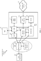
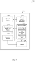
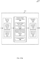
- the LTE network architecture 100 may be referred to as an Evolved Packet System (EPS).
- the LTE network architecture 100 may include one or more user equipment (UE) 102, an Evolved UMTS Terrestrial Radio Access Network (E-UTRAN) 104, an Evolved Packet Core (EPC) 110, a Home Subscriber Server (HSS) 120, and an Operator's Internet Protocol (IP) Services 122.
- the EPS can interconnect with other access networks, but for simplicity those entities/interfaces are not shown.
- the EPS provides packet-switched services, however, as those skilled in the art will readily appreciate, the various concepts presented throughout this disclosure may be extended to networks providing circuit-switched services.
- the E-UTRAN includes the base stations 106 and other base stations 108.
- the base station 106 provides user and control planes protocol terminations toward the UE 102.
- the base station 106 may be connected to the other base stations 108 via a backhaul (e.g., an X2 interface).
- the base station 106 provides an access point to the EPC 110 for a UE 102.
- the base station 106 is connected to the EPC 110.
- the EPC 110 may include a Mobility Management Entity (MME) 112, other MMEs 114, a Serving Gateway 116, a Multimedia Broadcast Multicast Service (MBMS) Gateway 124, a Broadcast Multicast Service Center (BM-SC) 126, a Packet Data Network (PDN) Gateway 118, and a multicell/multicast coordination entity (MCE) 128.
- MME Mobility Management Entity
- MBMS Multimedia Broadcast Multicast Service
- BM-SC Broadcast Multicast Service Center
- PDN Packet Data Network
- MCE multicell/multicast coordination entity
- the PDN Gateway 118 is connected to the Operator's IP Services 122.
- the Operator's IP Services 122 may include the Internet, an intranet, an IP Multimedia Subsystem (IMS), and a PS Streaming Service (PSS).
- the BM-SC 126 may provide functions for MBMS user service provisioning and delivery.
- the BM-SC 126 may serve as an entry point for content provider MBMS transmission, may be used to authorize and initiate MBMS Bearer Services within a PLMN, and may be used to schedule and deliver MBMS transmissions.
- the MBMS Gateway 124 may be used to distribute MBMS traffic to the base stations (e.g., 106, 108) belonging to a Multicast Broadcast Single Frequency Network (MBSFN) area broadcasting a particular service, and may be responsible for session management (start/stop) and for collecting eMBMS related charging information.
- the MCE 128 may be responsible for allocating time and frequency resources for multicell MBMS transmission. As such, the MCE 128 performs scheduling on the radio interface.
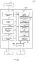
- the wireless communications system 200 includes a plurality of base stations (e.g ., access points, eNBs, or WLAN access points) 205, a number of user equipments (UEs) 215, and a core network 230.
- Some of the base stations 205 may communicate with the UEs 215 under the control of a base station controller (not shown), which may be part of the core network 230 or certain base stations 205 (e.g., access points or eNBs) in various embodiments.
- Some of the base stations 205 may communicate control information and/or user data with the core network 230 through backhaul 232.
- some of the base stations 205 may communicate, either directly or indirectly, with each other over backhaul links 234, which may be wired or wireless communication links.
- the wireless communications system 200 may support operation on multiple carriers (waveform signals of different frequencies).
- Multi-carrier transmitters can transmit modulated signals simultaneously on the multiple carriers.
- each communications link 225 may be a multi-carrier signal modulated according to various radio technologies.
- Each modulated signal may be sent on a different carrier and may carry control information (e.g., reference signals, control channels, etc.), overhead information, data, etc.
- the base stations 205 may wirelessly communicate with the UEs 215 via one or more base station antennas. Each of the base stations 205 may provide communication coverage for a respective coverage area 210.
- a base station 205 may be referred to as a access point, a base transceiver station (BTS), a radio base station, a radio transceiver, a basic service set (BSS), an extended service set (ESS), a NodeB, an evolved NodeB (eNB), a Home NodeB, a Home eNodeB, a WLAN access point, a WiFi node or some other suitable terminology.
- the coverage area 210 for an access point may be divided into sectors making up only a portion of the coverage area (not shown).
- the wireless communications system 200 may include base stations 205 of different types (e.g., macro, micro, and/or pico base stations).
- the base stations 205 may also utilize different radio technologies, such as cellular and/or WLAN radio access technologies.
- the base stations 205 may be associated with the same or different access networks or operator deployments.
- the coverage areas of different base stations 205, including the coverage areas of the same or different types of base stations 205, utilizing the same or different radio technologies, and/or belonging to the same or different access networks, may overlap.
- the wireless communications system 200 may include an LTE/LTE-A communications system (or network) that supports one or more modes of operation or deployment scenarios for LTE/LTE-A in an unlicensed spectrum, and may employ multiple component carriers having synchronized listening intervals and coordinated CCAs.
- the wireless communications system 200 may support enhanced Multimedia Broadcast Multicast Services (eMBMS), which is a point-to-multipoint interface specification designed to provide efficient delivery of broadcast and multicast services both within a cell as well as within a network such as the wireless communications system 200.
- eMBMS enhanced Multimedia Broadcast Multicast Services
- SFN single-frequency network
- Such eMBMS operation may be facilitated by eMBMS coordination manager 240, and will be described in more detail below.
- the wireless communications system 200 may support wireless communications using an unlicensed spectrum and an access technology different from LTE/LTE-A in an unlicensed spectrum, or a licensed spectrum and an access technology different from LTE/LTE-A.
- LTE/LTE-A communications systems the term evolved NodeB or eNB may be generally used to describe of the base stations 205.
- the wireless communications system 200 may be a Heterogeneous LTE/LTE-A network in which different types of base stations provide coverage for various geographical regions. For example, each base station 205 may provide communication coverage for a macro cell, a pico cell, a femto cell, and/or other types of cell.
- Small cells such as pico cells, femto cells, and/or other types of cells may include low power nodes or LPNs.
- a macro cell generally covers a relatively large geographic area (e.g ., several kilometers in radius) and may allow unrestricted access by UEs with service subscriptions with the network provider.
- a pico cell would generally cover a relatively smaller geographic area and may allow unrestricted access by UEs with service subscriptions with the network provider.
- a femto cell would also generally cover a relatively small geographic area (e.g., a home) and, in addition to unrestricted access, may also provide restricted access by UEs having an association with the femto cell (e.g., UEs in a closed subscriber group (CSG), UEs for users in the home, and the like).
- a base eNB for a macro cell may be referred to as a macro eNB.
- An eNB for a pico cell may be referred to as a pico eNB.
- an eNB for a femto cell may be referred to as a femto eNB or a home eNB.
- An eNB may support one or multiple (e.g., two, three, four, and the like) cells.
- the core network 230 may communicate with the base stations 205 via a backhaul 232 (e.g., S1, etc.).
- the base stations 205 may also communicate with one another, e.g., directly or indirectly via backhaul links 234 (e.g., X2, etc.) and/or via backhaul 232 (e.g., through core network 230).
- the wireless communications system 200 may support synchronous or asynchronous operation. For synchronous operation, the base stations may have similar frame and/or gating timing, and transmissions from different base stations may be approximately aligned in time. For asynchronous operation, the base stations may have different frame and/or gating timing, and transmissions from different base stations may not be aligned in time.
- the UEs 215 may be dispersed throughout the wireless communications system 200, and each UE 215 may be stationary or mobile.
- a UE 215 may also be referred to by those skilled in the art as a mobile device, a mobile station, a subscriber station, a mobile unit, a subscriber unit, a wireless unit, a remote unit, a wireless device, a wireless communication device, a remote device, a mobile subscriber station, an access terminal, a mobile terminal, a wireless terminal, a remote terminal, a handset, a user agent, a mobile client, a client, or some other suitable terminology.
- a UE 215 may be a cellular phone, a personal digital assistant (PDA), a wireless modem, a wireless communication device, a handheld device, a tablet computer, a laptop computer, a cordless phone, a wearable item such as a watch or glasses, a wireless local loop (WLL) station, or the like.
- a UE 215 may be able to communicate with macro eNBs, pico eNBs, femto eNBs, relays, and the like.
- a UE 215 may also be able to communicate over different access networks, such as cellular or other WWAN access networks, or WLAN access networks.
- the communications links 225 shown in wireless communications system 200 may include uplinks for carrying uplink (UL) transmissions (e.g., from a UE 115 to a base station 205) and/or downlinks for carrying downlink (DL) transmissions (e.g., from a base station 205 to a UE 215).
- the UL transmissions may also be called reverse link transmissions, while the DL transmissions may also be called forward link transmissions.
- the downlink transmissions may be made using a licensed spectrum, an unlicensed spectrum, or both.
- the uplink transmissions may be made using a licensed spectrum, an unlicensed spectrum, or both.
- various deployment scenarios for LTE/LTE-A in an unlicensed spectrum may be supported including a supplemental downlink mode in which LTE downlink capacity in a licensed spectrum may be offloaded to an unlicensed spectrum, a carrier aggregation mode in which both LTE downlink and uplink capacity may be offloaded from a licensed spectrum to an unlicensed spectrum, and a standalone mode in which LTE downlink and uplink communications between a base station (e.g., an eNB) and a UE may take place in an unlicensed spectrum.
- a base station e.g., an eNB
- OFDMA communications signals may be used in the communications links 225 for LTE downlink transmissions in an unlicensed and/or a licensed spectrum
- SC-FDMA communications signals may be used in the communications links 225 for LTE uplink transmissions in an unlicensed and/or a licensed spectrum.
- Transmissions using the unlicensed spectrum may be carried using one or more carrier frequencies in a frequency band.
- a frequency band for example, may be divided into multiple carrier frequencies, and each carrier frequency may have the same bandwidth or different bandwidth. For example, each carrier frequency may occupy 20 MHz of a 5GHz frequency band.
- a device seeking to transmit using unlicensed spectrum may be required to verify that the spectrum is available for use in such a transmission, that is, the spectrum is not already in use by one or more other devices.
- a CCA may be used to determine availability of the unlicensed spectrum. Performance of a CCA generally involves checking that the desired spectrum is not otherwise occupied prior to initiating transmissions.
- CCA opportunities are coordinated across multiple base stations 205, and may occur at periodic listening intervals, such as every 10 ms.
- a transmitting entity, such as a base station 205 may desire channel access and perform a CCA to determine if a particular carrier frequency in the unlicensed spectrum is occupied. If the particular carrier frequency in the unlicensed spectrum is occupied, the base station 205 waits until the next CCA opportunity before attempting to obtain channel access again on the associated carrier frequency.
- a set of base stations 205 may provide a broadcast signal, such as a signal broadcast according to eMBMS techniques, using an unlicensed spectrum.
- the eMBMS coordination manager 240 in such embodiments may provide control information to each base station 205 that defines the characteristics of the broadcast signal, such as resources to be used to transmit the broadcast signal, timing of content to be transmitted using the broadcast signal, etc.
- each base station 205 performs a CCA and, if the associated portion of the unlicensed spectrum is available, will transmit the broadcast signal according to the information provided by the eMBMS coordination manager 240.
- a CCA fails for a particular base station 205, meaning that another transmitter within a vicinity of the base station 205 is transmitting using the unlicensed spectrum, the particular base station 205 will not transmit signals using the unlicensed spectrum for the transmission period associated with the listening interval (although the base station 205 may transmit one or more signals using the licensed spectrum).
- a UE 215 receiving such a broadcast signal may thus receive the broadcast signal from different base stations 205 during different time periods.
- transmission of broadcast signals using unlicensed spectrum may be coordinated so as to provide such broadcast transmissions in deployments where a UE 215 may receive signals from multiple base stations 205, thus if one or more base stations 205 are not transmitting the broadcast signal, a UE 215 may still receive the broadcast signal from another base station 205 having an overlapping coverage area. Additional details regarding the implementation of broadcast signals in various LTE deployment scenarios or modes of operation for unlicensed spectrum in a system, such as the wireless communications system 200, as well as other features and functions related to the operation of LTE/LTE-A in an unlicensed spectrum, are provided below with reference to FIGS. 3A-40 .
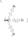
- FIG. 3A shows a diagram of a wireless communications system 300 illustrating examples of a supplemental downlink mode, a carrier aggregation mode, and a standalone mode for an LTE network that supports LTE/LTE-A communications over an unlicensed spectrum.
- the wireless communications system 300 may be an example of portions of the wireless communications system 200 of FIG. 2 .
- the base station 205-a may be an example of the base stations 205 of FIG. 2
- the UEs 215-a may be examples of the UEs 215 of FIG. 2 .
- the base station 205-a may transmit OFDMA communications signals to a UE 215-a using a downlink 305.
- the downlink 305 is associated with a frequency F1 in an unlicensed spectrum.
- the base station 205-a may transmit OFDMA communications signals to the same UE 215-a using a bidirectional link 310 and may receive SC-FDMA communications signals from that UE 215-a using the bidirectional link 310.
- the bidirectional link 310 is associated with a frequency F4 in a licensed spectrum.
- the downlink 305 in the unlicensed spectrum and the bidirectional link 310 in the licensed spectrum may operate concurrently.
- the downlink 305 may provide a downlink capacity offload for the base station 205-a.
- the downlink 305 may be used for unicast services (e.g., addressed to one UE) services or for multicast services (e.g., addressed to several UEs). This scenario may occur with any service provider (e.g., traditional mobile network operator or MNO) that uses a licensed spectrum and needs to relieve some of the traffic and/or signaling congestion.
- MNO mobile network operator
- the base station 205-a may transmit OFDMA communications signals to a UE 215-a using a bidirectional link 315 and may receive SC-FDMA communications signals from the same UE 215-a using the bidirectional link 315.
- the bidirectional link 315 is associated with the frequency F1 in the unlicensed spectrum.
- the base station 205-a may also transmit OFDMA communications signals to the same UE 215-a using a bidirectional link 320 and may receive SC-FDMA communications signals from the same UE 215-a using the bidirectional link 320.
- the bidirectional link 320 is associated with a frequency F2 in a licensed spectrum.
- the bidirectional link 315 may provide a downlink and uplink capacity offload for the base station 205-a. Like the supplemental downlink described above, this scenario may occur with any service provider (e.g., MNO) that uses a licensed spectrum and needs to relieve some of the traffic and/or signaling congestion.
- MNO service provider
- the base station 205-a may transmit OFDMA communications signals to a UE 215-a using a bidirectional link 325 and may receive SC-FDMA communications signals from the same UE 215-a using the bidirectional link 325.
- the bidirectional link 325 is associated with the frequency F3 in an unlicensed spectrum.
- the base station 205-a may also transmit OFDMA communications signals to the same UE 115-a using a bidirectional link 330 and may receive SC-FDMA communications signals from the same UE 215-a using the bidirectional link 330.
- the bidirectional link 330 is associated with the frequency F2 in the licensed spectrum.
- the bidirectional link 325 may provide a downlink and uplink capacity offload for the base station 205-a.
- This example and those provided above are presented for illustrative purposes and there may be other similar modes of operation or deployment scenarios that combine LTE communications in a licensed spectrum and LTE communications in an unlicensed spectrum for capacity offload.
- an operational configuration may include a bootstrapped mode (e.g., supplemental downlink, carrier aggregation) that uses the LTE primary component carrier (PCC) on the licensed spectrum and the LTE secondary component carrier (SCC) on the unlicensed spectrum.
- PCC primary component carrier
- SCC LTE secondary component carrier
- control for LTE communications in an unlicensed spectrum may be transported over the LTE uplink (e.g., uplink portion of the bidirectional link 310).
- LBT listen-before-talk
- CSMA carrier sense multiple access
- LBT may be implemented on the base station (e.g., eNB) by, for example, using a periodic (e.g., every 10 milliseconds) clear channel assessment (CCA) and/or a grab-and-relinquish mechanism aligned to a radio frame boundary.
- CCA clear channel assessment
- data and control may be communicated in LTE (e.g., bidirectional links 310, 320, and 330) while data may be communicated in an unlicensed spectrum (e.g., bidirectional links 315 and 325).
- LTE Long Term Evolution
- unlicensed spectrum e.g., bidirectional links 315 and 325.
- the carrier aggregation mechanisms supported when using an unlicensed spectrum may fall under a hybrid frequency division duplex-time division duplex (FDD-TDD) carrier aggregation or a TDD-TDD carrier aggregation with different symmetry across component carriers.
- FDD-TDD hybrid frequency division duplex-time division duplex
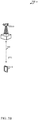
- FIG. 3B shows a diagram of a wireless communications system 300-a illustrating an example of a standalone mode for an LTE using an unlicensed spectrum.
- the wireless communications system 300-a may be an example of portions of the wireless communications system 200 of FIG. 2 .
- the base station 205-b may be an example of the base stations 205 of FIG. 2 and the base station 205-a of FIG. 3A
- the UE 215-b may be an example of the UEs 215 of FIG. 2 and the UEs 215-a of FIG. 3A .
- the base station 205-b may transmit OFDMA communications signals to the UE 215-b using a bidirectional link 340 and may receive SC-FDMA communications signals from the UE 215-b using the bidirectional link 340.
- the bidirectional link 340 is associated with the frequency F3 in an unlicensed spectrum described above with reference to FIG. 3A .
- the standalone mode may be used in non-traditional wireless access scenarios, such as in-stadium access ( e.g., unicast, multicast).
- the typical service provider for this mode of operation may be a stadium owner, cable company, event hosts, hotels, enterprises, and large corporations that do not have licensed spectrum.
- an operational configuration for the standalone mode may use the PCC on the unlicensed spectrum.
- LBT may be implemented on both the base station and the UE.
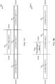
- FIG. 4 shows a diagram 400 illustrating an example of carrier aggregation when using LTE concurrently in licensed and unlicensed spectrum according to various embodiments.
- the carrier aggregation scheme in diagram 400 may correspond to the hybrid FDD-TDD carrier aggregation described above with reference to FIG. 3A .
- This type of carrier aggregation may be used in at least portions of the wireless communications system 200 of FIG. 2 .
- this type of carrier aggregation may be used in the base stations 205, and/or 205-a of FIG. 2 and/or 3A, and/or in the UEs 215, and/or 215-a of FIG. 2 and/or 3A.
- an FDD FDD-LTE
- a first TDD TDD1
- LTE-U LTE communications in an unlicensed spectrum
- a second TDD TDD2
- another FDD FDD-LTE
- TDD1 results in a DL:UL ratio of 6:4, while the ratio for TDD2 is 7:3.
- the different effective DL:UL ratios are 3:1, 1:3, 2:2, 3:1, 2:2, and 3:1.
- This example is presented for illustrative purposes and there may be other carrier aggregation schemes that combine the operations of LTE in a licensed spectrum and LTE in an unlicensed spectrum.
- a transmitting device such as a base station 205 or UE 215 (or a transmitter of a transmitting device) may use a gating interval (gated period) to gain access to a channel of the unlicensed spectrum.
- the gating interval may define the application of a contention-based protocol, such as a Listen Before Talk (LBT) protocol based on the LBT protocol specified in ETSI (EN 301 893).
- LBT Listen Before Talk
- the gating interval may indicate when a transmitting device needs to perform a clear channel assessment (CCA). The outcome of the CCA indicates to the transmitting device whether a channel of the unlicensed spectrum is available or in use.
- CCA clear channel assessment
- the gating interval may allow the transmitting device to use the channel - typically for a predefined period of time.
- the gating interval may prevent the transmitting device from using the channel for a period of time.
- a transmitting device may be useful for a transmitting device to generate a gating interval on a periodic basis and synchronize at least one boundary of the gating interval with at least one boundary of a periodic frame structure.
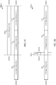
- FIG. 5A illustrates a first example 500 of a periodic gating interval 505 for a cellular downlink in an unlicensed spectrum.
- the periodic gating interval 505 may be used by a base station that supports LTE communications over an unlicensed spectrum. Examples of such a base station may be the base stations 205, 205-a, and/or 205-b of FIG. 2 , 3A , and/or 3B.
- the gating interval 505 may be used with the wireless communications system 200 of FIG. 2 and with portions of the wireless communications system 200 shown in FIG. 3A and/or 3B.
- the duration of the periodic gating interval 505 is shown to be equal to (or approximately equal to) the duration of the periodic frame structure 510 associated with the cellular downlink.
- “approximately equal” means the duration of the periodic gating interval 505 is within a cyclic prefix (CP) duration of the duration of the periodic frame structure 510.
- CP cyclic prefix
- At least one boundary of the periodic gating interval 505 may be synchronized with at least one boundary of the periodic frame structure 510.
- the periodic gating interval 505 may have boundaries that are aligned with the frame boundaries of the periodic frame structure 510.
- the periodic gating interval 505 may have boundaries that are synchronized with, but offset from, the frame boundaries of the periodic frame structure 510.
- the boundaries of the periodic gating interval 505 may be aligned with subframe boundaries of the periodic frame structure 510, or with subframe midpoint boundaries (e.g., the midpoints of particular subframes) of the periodic frame structure 510.
- each periodic frame structure 510 may include an LTE radio frame (e.g., an LTE radio frame (N-1), an LTE radio frame (N), or an LTE radio frame (N+1)).
- LTE radio frame may have a duration of ten milliseconds
- the periodic gating interval 505 may also have a duration of ten milliseconds.
- the boundaries of the periodic gating interval 505 may be synchronized with the boundaries (e.g ., frame boundaries, subframe boundaries, or subframe midpoint boundaries) of one of the LTE radio frames (e.g., the LTE radio frame (N)).
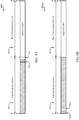
- FIG. 5B illustrates a second example 500-a of a periodic gating interval 505-a for a cellular downlink in an unlicensed spectrum.
- the periodic gating interval 505-a may be used by a base station that supports LTE communications over an unlicensed spectrum. Examples of such a base station may be the base stations 205, 205-a, and/or 205-b of FIG. 2 , 3A , and/or 3B.
- the gating interval 505-a may be used with the wireless communications system 200 of FIG. 2 and with portions of the wireless communications system 200 shown in FIG. 3A and/or 3B.
- the duration of the periodic gating interval 505-a is shown to be a sub-multiple of (or an approximate sub-multiple of) the duration of the periodic frame structure 510 associated with the cellular downlink.
- an "approximate sub-multiple of' means the duration of the periodic gating interval 505-a is within a cyclic prefix (CP) duration of the duration of a sub-multiple of (e.g., half) the periodic frame structure 510.
- CP cyclic prefix
- At least one boundary of the periodic gating interval 505-a may be synchronized with at least one boundary of the periodic frame structure 510.
- the periodic gating interval 505-a may have a leading or trailing boundary that is aligned with a leading or trailing frame boundary of the periodic frame structure 510.
- the periodic gating interval 505-a may have boundaries that are synchronized with, but offset from, each of the frame boundaries of the periodic frame structure 510.
- the boundaries of the periodic gating interval 505-a may be aligned with subframe boundaries of the periodic frame structure 510, or with sub frame midpoint boundaries (e.g., the midpoints of particular sub frames) of the periodic frame structure 510.
- each periodic frame structure 510 may include an LTE radio frame (e.g., an LTE radio frame (N-1), an LTE radio frame (N), or an LTE radio frame (N+1)).
- LTE radio frame may have a duration of ten milliseconds
- the periodic gating interval 505-a may have a duration of five milliseconds.
- the boundaries of the periodic gating interval 505-a may be synchronized with the boundaries (e.g., frame boundaries, subframe boundaries, or subframe midpoint boundaries) of one of the LTE radio frames (e.g., LTE radio frame (N)).
- FIG. 5C illustrates a third example 500-b of a periodic gating interval 505-b for a cellular downlink in an unlicensed spectrum.
- the periodic gating interval 505-b may be used by a base station that supports LTE communications over an unlicensed spectrum. Examples of such a base station may be the base stations 205, 205-a, and/or 205-b of FIG. 2 , 3A , and/or 3B.
- the gating interval 505-b may be used with the wireless communications system 200 of FIG. 2 and with portions of the wireless communications system 200 shown in FIG. 3A and/or 3B.
- the duration of the periodic gating interval 505-b is shown to be an integer multiple of (or an approximate integer multiple of) the duration of the periodic frame structure 510 associated with the cellular downlink.
- an "approximate integer multiple of' means the duration of the periodic gating interval 505-b is within a cyclic prefix (CP) duration of an integer multiple of (e.g., double) the duration of the periodic frame structure 510.
- CP cyclic prefix
- At least one boundary of the periodic gating interval 505-b may be synchronized with at least one boundary of the periodic frame structure 510.
- the periodic gating interval 505-b may have a leading boundary and a trailing boundary that are aligned with respective leading or trailing frame boundaries of the periodic frame structure 510.
- the periodic gating interval 505-b may have boundaries that are synchronized with, but offset from, the frame boundaries of the periodic frame structure 510.
- the boundaries of the periodic gating interval 505-b may be aligned with subframe boundaries of the periodic frame structure 510, or with subframe midpoint boundaries (e.g., the midpoints of particular subframes) of the periodic frame structure 510.
- each periodic frame structure 510 may include an LTE radio frame (e.g., an LTE radio frame (N-1), an LTE radio frame (N), or an LTE radio frame (N+1)).
- LTE radio frame may have a duration of ten milliseconds
- the periodic gating interval 505-b may have a duration of twenty milliseconds.
- the boundaries of the periodic gating interval 505-b may be synchronized with the boundaries (e.g., frame boundaries, subframe boundaries, or subframe midpoint boundaries) of one or two of the LTE radio frames (e.g., LTE radio frame (N) and LTE radio frame (N+1)).
- FIG. 5D illustrates a fourth example 500-c of a periodic gating interval 505-c for a cellular downlink in an unlicensed spectrum.
- the periodic gating interval 505-c may be used by a base station that supports LTE communications over an unlicensed spectrum. Examples of such a base station may be the base stations 205, 205-a, and/or 205-b of FIG. 2 , 3A , and/or 3B.
- the gating interval 505-c may be used with the wireless communications system 200 of FIG. 2 and with portions of the wireless communications system 200 shown in FIG. 3A and/or 3B.
- the duration of the periodic gating interval 505-c is shown to be a sub-multiple of (or an approximate sub-multiple of) the duration of the periodic frame structure 510 associated with the cellular downlink.
- the sub-multiple may be one-tenth of the duration of the periodic frame structure 510.
- At least one boundary of the periodic gating interval 505-c may be synchronized with at least one boundary of the periodic frame structure 510.
- the periodic gating interval 505-c may have a leading or trailing boundary that is aligned with a leading or trailing frame boundary of the periodic frame structure 510.
- the periodic gating interval 505-c may have boundaries that are synchronized with, but offset from, each of the frame boundaries of the periodic frame structure 510.
- the boundaries of the periodic gating interval 505-c may be aligned with subframe boundaries of the periodic frame structure 510, or with subframe midpoint boundaries (e.g., the midpoints of particular sub frames) of the periodic frame structure 510.
- each periodic frame structure 510 may include an LTE radio frame (e.g., an LTE radio frame (N-1), an LTE radio frame (N), or an LTE radio frame (N+1)).
- Each LTE radio frame may have a duration of ten milliseconds
- the periodic gating interval 505-c may have a duration of one millisecond (e.g., the duration of one subframe).
- the boundaries of the periodic gating interval 505-c may be synchronized with the boundaries ( e.g., frame boundaries, subframe boundaries, or subframe midpoint boundaries) of one of the LTE radio frames (e.g., LTE radio frame (N)).
- FIG. 6 illustrates a fifth example 600 of a periodic gating interval 505-d for a cellular downlink in an unlicensed spectrum.
- the periodic gating interval 505-d may be used by a base station that supports LTE communications over an unlicensed spectrum. Examples of such a base station may be the base stations 205, 205-a, and/or 205-b of FIG. 2 , 3A , and/or 3B.
- the gating interval 505 may be used with the wireless communications system 200 of FIG. 2 and with portions of the wireless communications system 200 shown in FIG. 3A and/or 3B.
- the duration of the periodic gating interval 505-d is shown to be equal to (or approximately equal to) the duration of a periodic frame structure 510-a associated with the cellular downlink.
- the boundaries of the periodic gating interval 505-d may be synchronized with (e.g., aligned with) the boundaries of the periodic frame structure 510-a.
- the periodic frame structure 510-a may include an LTE radio frame having ten subframes (e.g., SF0, SF1, ..., SF9).
- Subframes SF0 through SF8 may be downlink (D) subframes 610, and subframe SF9 may be a special (S') subframe 615.
- the D subframes 610 may collectively define a channel occupancy time of the LTE radio frame, and at least part of the S' subframe 615 may define a channel idle time.
- an LTE radio frame may have a maximum channel occupancy time (ON time) between one and 9.5 milliseconds, and a minimum channel idle time (OFF time) of five percent of the channel occupancy time (e.g., a minimum of 50 microseconds).
- the periodic gating interval 505-d may abide by these requirements of the LTE standard by providing a 0.5 millisecond guard period ( i.e., OFF time) as part of the S' sub frame 615.
- the S' subframe 615 may include one or more CCA slots 620 (e.g., time slots) in which the transmitting devices contending for a particular channel of an unlicensed spectrum may perform their CCAs.
- CCA slots 620 e.g., time slots
- the device may transmit one or more signals to reserve the channel until the end of the periodic gating interval 505-d.
- the one or more signals may in some cases include Channel Usage Beacon Signals (CUBS) 630.
- CUBS 630 may be used for both channel synchronization and channel reservation. That is, a device that performs a CCA for the channel after another device begins to transmit CUBS on the channel may detect the energy of the CUBS 630 and determine that the channel is currently unavailable.
- the transmitting device may use the channel for up to a predetermined period of time (e.g., one LTE radio frame) to transmit a waveform (e.g., an LTE-based waveform 640).
- a predetermined period of time e.g., one LTE radio frame
- a waveform e.g., an LTE-based waveform 640
- the gating interval may take the form of an LBT Fixed Based Equipment (LBT-FBE) gating interval or an LBT Load Based Equipment (LBT-LBE) gating interval.
- LBT-FBE LBT Fixed Based Equipment
- LBT-LBE LBT Load Based Equipment
- An LBT-FBE gating interval may have a fixed/periodic timing and may not be directly influenced by traffic demand (e.g., its timing can be changed through reconfiguration).
- traffic demand e.g., its timing can be changed through reconfiguration
- an LBT-LBE gating interval may not have a fixed timing (i.e., be asynchronous) and may be largely influenced by traffic demand.
- periodic gating interval 505 may be an LBT-FBE gating interval.
- a potential advantage of the periodic gating interval 505 described with reference to FIG. 5A is that it may preserve the ten millisecond LTE radio frame structure defined in the current LTE specification.
- the duration of a gating interval is less than the duration of an LTE radio frame (e.g., as descried with reference to FIG. 5B or 5D )
- the advantages of preserving the LTE radio frame structure no longer exist and an LBT-LBE gating interval may be advantageous.
- a potential advantage of using an LBT-LBE gating interval is that it may retain the subframe structure of LTE PHY channels, without any symbol puncturing at the beginning or end of the gating interval.
- a potential disadvantage of using an LBT-LBE gating interval is not being able to synchronize the use of a gating interval between the different base stations of an operator (e.g., because each base station uses a random back-off time for an extended CCA).
- FIGS. 7A and 7B illustrate how a contention-based protocol such as LBT may be implemented within an S' subframe 625-a of a gating interval, such as an S' subframe of the ten millisecond gating interval 505-d described with reference to FTG. 6.
- the contention-based protocol may be used with, for example, the base stations 205, 205-a, and/or 205-b of FIG. 2 , 3A , and/or 3B.
- the contention-based protocol may be used with the wireless communications system 200 of FIG. 2 and with portions of the wireless communications system 200 shown in FIG. 3A and/or 3B.
- each of the guard period 705 and the CCA period 710 may have a duration of 0.5 milliseconds and include seven OFDM symbol positions 715.
- each of the OFDM symbol positions 715 in the CCA period 710 may be transformed into a CCA slot 620-a upon a base station selecting the OFDM symbol position 715 for performing a CCA.
- the same or different ones of the OFDM symbol positions 715 may be pseudo-randomly selected by ones of multiple base stations, thereby providing a sort of CCA time dithering.
- the base stations may be operated by a single LTE operator or different operators.
- An OFDM symbol position 715 may be pseudo-randomly selected in that a base station may be configured to select different ones of the OFDM symbol positions at different times, thereby giving each of the multiple base stations an opportunity to select the OFDM symbol position 715 that occurs earliest in time.
- the first base station to perform a successful CCA has an opportunity to reserve a corresponding channel or channels of an unlicensed spectrum, and a base station's pseudo-random selection of an OFDM symbol position 715 for performing a CCA ensures that it has the same chance of performing a successful CCA as every other base station.
- the base stations may in some cases be configured to select the same CCA slot 620-a.
- FIGS. 8A and 8B provide examples of how an S' subframe such as the S' subframe 625-a described with reference to FIG. 7A and/or 7B may be used in conjunction with a current gating interval 505.
- the current gating intervals 505-e, 505-g shown in FIGS. 8A and 8B may be examples of the ten millisecond gating interval 505-d described with reference to FIG. 6 .
- the use of S' subframes in conjunction with a current gating interval may be handled by, for example, the base stations 205, 205-a, and/or 205-b of FIG. 2 , 3A , and/or 3B.
- the use of S' subframes in conjunction with a current gating interval may be handled may be the wireless communications system 200 of FIG. 2 and with portions of the wireless communications system 200 shown in FIG. 3A and/or 3B.
- FIG. 8A provides an example 800 in which an S' subframe is included as a last subframe of the current gating interval 505-e.
- the guard period 705-a and the CCA period 710-a of the S' subframe occur at the end of the current gating interval 505-e, just prior to a trailing boundary of the current gating interval 505-e and the start of a next transmission interval 505-f.
- the next transmission interval 505-f may be gated ON or gated OFF for a downlink transmission of each of a number of transmitting devices, depending on whether a CCA performed by the transmitting device indicates that an unlicensed spectrum is available or unavailable during the next transmission interval 505-f.
- the next transmission interval 505-f may also be a next gating interval.
- FIG. 8B provides an example 800-a in which an S' subframe is included as a first subframe of the current gating interval 505-g.
- the guard period 705-b and the CCA period 710-b of the S' subframe occur at the start of the current gating interval 505-g, just after a leading boundary of the current gating interval 505-g.
- the next transmission interval 505-h may be gated ON or gated OFF for a downlink transmission of each of a number of transmitting devices, depending on whether a CCA performed by the transmitting device indicates that an unlicensed spectrum is available or unavailable during the next transmission interval 505-h.
- the next transmission interval 505-h may also be a next gating interval.
- FIG. 8C provides an example 800-b of how the performance of CCAs for an unlicensed spectrum (or a channel of the unlicensed spectrum) may be synchronized across multiple base stations 205.
- the multiple base stations 205 may include an eNB1 and an eNB2.
- the performance of CCAs may be provided by, for example, the base stations 205, 205-a, and/or 205-b of FIG. 2 , 3A , and/or 3B.
- the performance of CCAs may be used in the wireless communications system 200 of FIG. 2 and with portions of the wireless communications system 200 shown in FIG. 3A and/or 3B.
- an S' subframe 625-b within a current gating interval of the eNB1 may be synchronized with an S' subframe 625-c within a current gating interval of the eNB2. Also, and because of a synchronized pseudo-random CCA slot selection processes implemented by each eNB, the eNB2 may select a CCA slot 620-c that occurs at a different time (e.g., different OFDM symbol position) than the CCA slot 620-b selected by eNB1.
- the eNB1 may select a CCA slot 620-b aligned with the fifth OFDM symbol position of the aligned CCA periods of the S' subframes 625-b and 625-c, and the eNB2 may select a CCA slot 620-c aligned with the third OFDM symbol position of the aligned CCA periods.
- a next transmission interval following the synchronized S' subframes 625-b and 625-c may begin after the CCA periods of the S' subframes 625-b and 625-c and start with a D subframe, as shown. Because the CCA slot 620-c of the eNB2 is scheduled first in time, the eNB2 has a chance to reserve the next transmission interval before the eNB1 has a chance to reserve the next transmission interval.
- the eNB1 may be provided the first chance to reserve a later transmission interval (e.g., because its CCA slot may occur at an earlier time than the CCA slot of the eNB2 in a later gating interval).
- FIG. 8C shows there is a WiFi transmission (Tx) activity that coincides with a portion of the aligned CCA periods of the S' subframes 625-b and 625-c.
- Tx WiFi transmission
- the eNB2 may determine as a result of performing its CCA that the unlicensed spectrum is unavailable, and may gate OFF a downlink transmission 805-a in the unlicensed spectrum for the next transmission interval.
- a downlink transmission of the eNB2 may therefore be blocked as a result of the WiFi Tx activity occurring during performance of the eNB2's CCA.
- the eNB1 may perform its CCA. Because of the timing of the CCA slot 620-b selected by the eNB1, the eNB1 may determine as a result of performing its CCA that the unlicensed spectrum is available (e.g., because the WiFi Tx activity does not occur during the CCA slot 620-b, and because the eNB2 was not able to reserve the next transmission interval at an earlier time). The eNB1 may therefore reserve the next transmission interval and gate ON a downlink transmission 805 in the unlicensed spectrum for the next transmission interval. Methods for reserving the unlicensed spectrum (or a channel of the unlicensed spectrum) are described in detail later in this description.
- FIGS. 7A , 7B , 8A, 8B , and 8C provide examples of how a CCA slot 620 may be selected in the context of a ten millisecond gating interval, such as the gating interval 505-d described with reference to FIG. 6 .
- FIGS. 8D , 8E , 8F , and 8G provide examples of how a CCA slot 620 may be selected in the context of a one or two millisecond gating interval.
- a gating interval of ten milliseconds may provide advantages such as a low gating interval overhead in the presence of a low WiFi activity, and an ability to retain the subframe-based PHY channel design of existing LTE channels.
- a long channel idle time e.g., 0.5+ milliseconds, depending on a CCA delay induced by CCA dithering
- a short contention window transmit opportunity e.g., a transmit opportunity during the guard period 705 described with reference to FIGS. 7A and 7B
- a gating interval of, for example, one or two milliseconds may lead to a higher gating interval overhead, and may require more extensive changes to the LTE PHY channel design to support sub-millisecond transmit durations.
- a gating interval of perhaps one or two milliseconds may mitigate or eliminate the aforementioned disadvantages associated with a ten millisecond gating interval.
- FIG. 8D provides an example 800-c of a one millisecond gating interval 505-i.
- a one millisecond gating interval may be used by the base stations 205, 205-a, and/or 205-b of FIG. 2 , 3A , and/or 3B.
- the one millisecond gating interval may be used in the wireless communications system 200 of FIG. 2 and with portions of the wireless communications system 200 shown in FIG. 3A and/or 3B.
- the current LTE specification requires a channel occupancy time (ON time) ⁇ one millisecond, and a channel idle time ⁇ five percent of the channel occupancy time.
- the current LTE specification dictates a minimum gating interval duration of 1.05 milliseconds.
- the LTE specification could be relaxed to require a minimum channel occupancy time of perhaps 0.95 milliseconds, then a one millisecond gating interval would be possible.
- a gating interval 505-i of one millisecond may include 14 OFDM symbols (or symbol positions).
- a downlink transmission may occur during the first 13 OFDM symbols of the gating interval 505-i.
- Such a downlink transmission may have a duration (or channel occupancy time) of 929 microseconds.
- a channel occupancy time of 929 microseconds would require a channel idle time or guard period 705-a of 48 microseconds, which is less than the 71.4 microsecond duration of one OFDM symbol.
- the channel idle time or guard period 705-a of 48 microseconds, as well as one or more CCA slots 620-d, may be provided during the 14th OFDM symbol position.
- two CCA slots 620-d having a total duration of 20 microseconds may be provided during the 14th OFDM symbol position, thereby enabling some amount of CCA randomization (dithering).
- each CCA slot 620-d in the example 800-c has a duration of less than one OFDM symbol.
- the gating interval 505-i is common reference signal (CRS) friendly.
- An example 800-d of a one millisecond gating interval 505-j that is UE-specific reference signal (UERS) friendly is shown in FIG. 8E . Similar to the gating interval 505-i, the gating interval 505-j includes 14 OFDM symbols. However, the channel idle time or guard period 705-b and CCA slots 620-e are provided in the first OFDM symbol position.
- a successful CCA performed during a CCA slot 620-e of the current gating interval 505-j thereby enables the unlicensed spectrum to be reserved, and enables a downlink transmission to be made, in the current gating interval.
- the next transmission interval is therefore included within the current gating interval.
- FIG. 8F provides an example 800-e of a two millisecond gating interval 505-k.
- a two millisecond gating interval may be used by the base stations 205, 205-a, and/or 205-b of FIG. 2 , 3A , and/or 3B.
- the two millisecond gating interval may be used in the wireless communications system 200 of FIG. 2 and with portions of the wireless communications system 200 shown in FIG. 3A and/or 3B.
- the two millisecond gating interval 505-k complies with the current LTE specification requirements for maximum channel occupancy time and minimum channel idle time.
- the gating interval 505-k may include a D subframe 610-a and an S' subframe 625-d.
- the S' subframe is configured somewhat differently than previously described S' subframes. More particularly, the first 12 OFDM symbol positions of the S' subframe, as well as the 14 OFDM symbol positions of the preceding D subframe, may be used for a downlink transmission upon performing a successful CCA during a CCA slot 620-f preceding the gating interval 505-k.
- the channel occupancy time may therefore be 1.857 milliseconds, requiring a channel idle time or guard period 705-c of 96 microseconds.
- the channel idle time or guard period 705-c may therefore occupy the 13th OFDM symbol position of the S' subframe and part of the 14th OFDM symbol position of the S' subframe.
- the remaining duration of the 14th OFDM symbol position may be filled, at least in part, by a number of CCA slots 620-f.
- the number of CCA slots 620-f may be three CCA slots 620-f, which provides a slightly greater amount of CCA randomization (dithering) than the one millisecond gating intervals described with reference to FIGS. 8D and 8E .
- the gating interval 505-k is CRS friendly.
- An example 800-f of a two millisecond gating interval 505-1 that is UERS friendly is shown in FIG. 8G . Similar to the gating interval 505-k, the gating interval 505-1 includes a D subframe 625-e and an S' subframe 610-b. However, the temporal order of the subframes is reversed, with the S' subframe 610-b occurring first in time and the D subframe 625-e occurring later in time.
- the channel idle time or guard period 705-d and CCA slots 620-g are provided in the first OFDM symbol position of the S' subframe 610-b.
- a successful CCA performed during a CCA slot 620-g of the current gating interval 505-1 thereby enables the unlicensed spectrum to be reserved, and enables a downlink transmission 810 to be made, in the current gating interval.
- the next transmission interval is therefore included within the current gating interval.
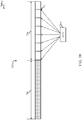
- FIG. 9 shows a diagram 900 illustrating communications between a base station 205-c and a UE 215-c.
- the base station 205-c may be an example of the base stations 205, 205-a, and/or 205-b of FIG. 2 , 3A , and/or 3B.
- the UE 215-c may be an example of the UEs 215, 215-a, and/or 215-b of FIG. 2 , 3A , and/or 3B.
- the base station 205-c and the UE 215-c may be used in the wireless communications system 200 of FIG. 2 and with portions of the wireless communications system 200 shown in FIG. 3A and/or 3B.
- the base station 205-c may communicate with the UE 215-c via a downlink 910 in an unlicensed spectrum, and the UE 215-c may communicate with the base station 205-c via a primary component carrier (PCC) uplink 905 in a licensed spectrum.
- PCC primary component carrier
- the UE 215-c may transmit feedback information to the base station 205-c via the PCC uplink 905, and the base station 205-c may receive the feedback information from the UE 215-c via the PCC uplink 905.
- the feedback information may address (or pertain to) signals transmitted from the base station 205-c to the UE 215-c via the downlink 910. Transmitting feedback information for the unlicensed spectrum via the licensed spectrum may improve the reliability of feedback information for the unlicensed spectrum.
- the feedback information may in some cases include feedback information for at least one transmission interval gated from the downlink 910.
- the feedback information may include channel state information (CSI), such as CSI for the downlink 910.
- CSI channel state information
- the CSI may include long-term CSI.
- the CSI may include short-term CSI.
- the long-term CSI may include, for example, radio resource management (RRM) information that captures the details of the channel interference environment (e.g., information identifying each source of dominant interference, whether it be a WiFi, station (STA), and/or base station, for example; information identifying an average strength and/or spatial characteristics of each interfering signal; etc.).
- RRM radio resource management
- the short-term CSI may include, for example, a CQI, a rank indicator (RI), and/or a pre-coding matrix indicator.
- the CSI may be sent from a UE 215-c to a base station 205-c, via the PCC uplink 905, in a second subframe following the start of downlink transmissions in a current transmission interval in the unlicensed spectrum.
- the feedback information may include HARQ feedback information, such as HARQ feedback information for the downlink 910.
- HARQ may ignore transmission intervals where downlink transmissions were gated OFF.
- HARQ may be used for transmission intervals where downlink transmissions are gated ON, and a simple automated repeat request (ARQ) may be used for transmission intervals where downlink transmissions are gated OFF. Both examples may retain almost full HARQ functionality in the context of a single deployment with no WiFi interference.
- the second example may be forced to predominantly use ARQ, in which case CSI may become the main tool for link adaptation.
- Asynchronous HARQ may be transmitted in a manner that is unaffected by gating of the unlicensed spectrum.
- a downlink transmission is not acknowledged (NAK'd)
- NAK'd When a downlink transmission is not acknowledged (NAK'd), a best effort HARQ retransmission may be made via the downlink 910. However, after a timeout period, the NAK'd packet may be recovered through radio link control (RLC) retransmissions via the downlink 910 or a PCC downlink.
- RLC radio link control
- the base station 205-c may in some cases use both the long-term CSI and the short-term CSI to select a modulation and coding scheme (MCS) for the downlink 910 in the unlicensed spectrum.
- MCS modulation and coding scheme
- the HARQ may then be used to fine-tune the served spectral efficient of the downlink 910 in real-time.
- FIG. 10 shows a diagram 1000 illustrating examples of normal and robust subframes in an unlicensed spectrum according to various embodiments.
- the normal and robust subframes may be transmitted by base stations that support LTE/LTE-A communications in an unlicensed spectrum. Examples of such base stations may be the base stations 205, 205-a, and/or 205-b of FIG. 2 , 3A , and/or 3B.
- the normal and robust subframes may be used by UEs that support LTE/LTE-A communications in an unlicensed spectrum. Examples of such UEs may be the UEs 215, 215-a, and/or 215-b of FIG. 2 , 3A , and/or 3B.
- a normal legacy carrier type (LCT) subframe 1005 is shown.
- Normal LCT subframes 1005 may be used for LCT waveforms and may carry time-division multiplexed (TDM) PDCCH and CRS.
- TDM time-division multiplexed
- CRS normal new carrier type
- Normal NCT subframes 1015 may be used for NCT waveforms but may not include TDM PDCCH and CRS. Instead, a UE may use channel state information-reference signals (CSI-RS) for feedback and UE-RS for demodulation.
- CSI-RS channel state information-reference signals
- FIG. 10 shows a robust LCT subframe 1010 and a robust NCT subframe 1020.
- Robust subframes may differ from the normal ones in that they may include additional pilots (e.g., common pilots, enhanced CRS (eCRS)), which may be used to facilitate time-frequency tracking and channel estimation at the UE after a long gated-OFF period of LTE DL transmissions.
- additional pilots e.g., common pilots, enhanced CRS (eCRS)
- eCRS enhanced CRS
- SYNC subframes e.g., subframes carrying PSS, SSS, (possibly) PBCH, in addition to other LTE subchannels
- the robust LCT subframes 1010 may be transmitted for the first X subframes after a gated-OFF period that is greater than Y subframes.
- the parameters X and Y may vary based on the structure of the subframes and usage rules, for example.
- Normal LCT subframes 1005 may be transmitted in all other gated-ON periods.
- the robust NCT subframes 1020 may be transmitted for the first X subframes after a gated-OFF period that is greater than Y subframes.
- the parameters X and Y may vary based on the structure of the subframes and usage rules, for example.
- Normal NCT subframes 1015 may be transmitted in all other gated-ON periods.
- FIG. 11 shows a diagram 1100 illustrating examples of Physical Uplink Control Channel (PUCCH) signals and Physical Uplink Shared Channel (PUSCH) signals for an unlicensed spectrum according to various embodiments.
- the PUCCH and PUSCH signals may be handled by base stations that support LTE/LTE-A communications in an unlicensed spectrum. Examples of such base stations may be the base stations 205, 205-a, and/or 205-b of FIG. 2 , 3A , and/or 3B.
- the PUCCH and PUSCH signals may be handled by UEs that support LTE/LTE-A communications in an unlicensed spectrum. Examples of such UEs may be the UEs 215, 215-a, and/or 215-b of FIG. 2 , 3A , and/or 3B.
- PUCCH and PUSCH signals are typically based on localized frequency division multiplexing (LFDM) waveforms that occupy a set of subcarriers where a different modulation symbol is sent for each subcarrier or some precoding is done before sending the frequency domain waveform.
- LFDM localized frequency division multiplexing
- small amounts of data available to be sent result in a small portion of the spectrum being occupied.
- TX-PSD transmit power spectral density
- each transmitter interleave its signals so they occupy every 1-out-of-every-Nth subcarrier (e.g., 1-out-of-10, 1-out-of-12), thereby leaving many subcarriers in the middle unoccupied.
- This approach may increase the nominal bandwidth occupancy to enable sending the waveform with a higher power (but still with low enough PSD to meet regulations).
- Interleaved frequency division multiplexing (IFDM) and interleaved orthogonal frequency division multiplexing (I-OFDM) signals may be used that occupy 1-out-of-Nth subcarrier in order to send signals confined to those subcarriers.
- IFDM waveforms are shown to generate PUCCH signals 1105 and PUSCH signals 1110 for transmission in an unlicensed spectrum.
- I-OFDM waveforms are shown to generate PUCCH signals 1115 and PUSCH signals 1120 for transmission in an unlicensed spectrum.
- FIG. 12 shows a diagram 1200 illustrating an example of load-based gating in an unlicensed spectrum according to various embodiments.
- the load-based gating may be performed by base stations that support LTE/LTE-A communications in an unlicensed spectrum. Examples of such base stations may be the base stations 205, 205-a, and/or 205-b of FIG. 2 , 3A , and/or 3B.
- LBT listen-before-talk
- FBE frame-based equipment
- LBT-FBE techniques rely in part on gating that preserves the 10 milliseconds radio frame structure of LTE.
- the use of shorter gating structures (1 milliseconds, 2 milliseconds), while allowing for periodic gating, may tend not to preserve the LTE frame structure.
- Using LBT-LBE may provide the potential benefit of retaining the subframe structure of LTE PHY channels without the need for symbol puncturing at the beginning or end of a gating period.
- the CCA may be similar to the CCA for LBT-FBE, but an extended CCA (which is not used in LBT-FBE), may be based on randomly selecting an integer N (e.g., 1 ⁇ N ⁇ q), and wait for N CCA durations where the channel is clear.
- N e.g. 1 ⁇ N ⁇ q
- Transmission at different subframes (SFs) in a subframe sequence of an unlicensed spectrum channel may be based on results from an extended CCA and from a CCA.
- An extended CCA may be based on a parameter 4 ⁇ q ⁇ 32, whose value is advertised by a vendor. When the channel has had a long break a CCA may need to be performed. If a CCA finds a clear channel, then it may be possible to start transmitting right away. If not, an extended CCA may be performed before transmission. Once transmission begins, it may continue for at most (13/32) ⁇ q ms (referred to as the maximum channel occupancy time), before another extended CCA may need to be performed. Upon a successful reception (from another node), ACK/NACK transmission may begin immediately (without a CCA), provided that the last successful CCA/extended CCA was performed less than a maximum channel occupancy time before.
- the minimum idle time for an extended CCA is approximately between 25 microseconds ( ⁇ s) and 0.6 milliseconds.
- CUPS may be used to fill the gap as described above.
- an extended CCA 620-m is performed at subframe (SF) 8 in a sequence 1205.
- the maximum channel occupancy time is such that a next extended CCA 620-m need not be performed until SF 18.
- LTE downlink transmissions may take place during SFs 9-12 as a result of the channel being free after the first extended CCA 620-m.
- a CCA 620-n may be performed at SF 15 for additional transmissions within the maximum channel occupancy time.
- LTE transmissions may take place at SFs 16 and 17.
- a second extended CCA 620-m may occur after the maximum channel occupancy time, which in this example leads to additional LTE transmissions in SFs 22-25.
- a block diagram illustrates a multiple-input multiple-output (MIMO) communication system 1300 including a base station (e.g., eNB) 1310 and a UE 1350.
- the eNB 1310 and the UE 1350 may support LTE-based communications using a licensed and/or unlicensed spectrum.
- the base station 1310 may be an example of one or more aspects of the base stations or devices 105, 205, 205-a, 205-b, 205-c, 2105, 2305, 2355, and/or 2405 described with reference to FIG.
- the system 1300 may illustrate aspects of the wireless communications system 200 of FIG. 2 , and/or portions of the wireless communications systems described with reference to FIG. 2 , 3A , 3B , 9 , 21A , and/or 21B.
- a controller/processor 1340 In the downlink (DL), upper layer packets from the core network are provided to a controller/processor 1340.
- the controller/processor 1375 may implement the functionality of the L2 layer.
- the controller/processor 1375 may provide header compression, ciphering, packet segmentation and reordering, multiplexing between logical and transport channels, and radio resource allocations to the UE 1350 based on various priority metrics.
- the controller/processor 1375 may also be responsible for HARQ operations, retransmission of lost packets, and signaling to the UE 1350.
- the transmit (TX) processor 1316 may implement various signal processing functions for a L1 layer (i.e., physical layer).
- the signal processing functions include coding and interleaving to facilitate forward error correction (FEC) at the UE 1350 and mapping to signal constellations based on various modulation schemes (e.g., binary phase-shift keying (BPSK), quadrature phase-shift keying (QPSK), M-phase-shift keying (M-PSK), M-quadrature amplitude modulation (M-QAM)).
- FEC forward error correction
- BPSK binary phase-shift keying
- QPSK quadrature phase-shift keying
- M-PSK M-phase-shift keying
- M-QAM M-quadrature amplitude modulation
- Each stream is then mapped to an OFDM subcarrier, multiplexed with a reference signal (e.g., pilot) in the time and/or frequency domain, and then combined together using an Inverse Fast Fourier Transform (IFFT) to produce a physical channel carrying a time domain OFDM symbol stream.
- the OFDM stream is spatially precoded to produce multiple spatial streams.
- Channel estimates from a channel estimator 1374 may be used to determine the coding and modulation scheme, as well as for spatial processing.
- the channel estimate may be derived from a reference signal and/or channel condition feedback transmitted by the UE 1350.
- Each spatial stream may then be provided to a different antenna 1320 via a separate transmitter 1318TX.
- Each transmitter 1318TX may modulate an RF carrier with a respective spatial stream for transmission.
- each receiver 1354RX receives a signal through its respective antenna 1352.
- Each receiver 1354RX recovers information modulated onto an RF carrier and provides the information to the receive (RX) processor 1356.
- the RX processor 1356 may implement various signal processing functions of the L1 layer.
- the RX processor 1356 may perform spatial processing on the information to recover any spatial streams destined for the UE 1350. If multiple spatial streams are destined for the UE 1350, they may be combined by the RX processor 1356 into a single OFDM symbol stream.
- the RX processor 1356 then converts the OFDM symbol stream from the time-domain to the frequency domain using a Fast Fourier Transform (FFT).
- FFT Fast Fourier Transform
- the frequency domain signal comprises a separate OFDM symbol stream for each subcarrier of the OFDM signal.
- the symbols on each subcarrier, and the reference signal, are recovered and demodulated by determining the most likely signal constellation points transmitted by the base station 1310. These soft decisions may be based on channel estimates computed by the channel estimator 1358.
- the soft decisions are then decoded and deinterleaved to recover the data and control signals that were originally transmitted by the base station 1310 on the physical channel.
- the data and control signals are then provided to the controller/processor 1359.
- the controller/processor 1359 may implement a L2 layer.
- the controller/processor can be associated with a memory 1360 that stores program codes and data.
- the memory 1360 may be referred to as a computer-readable medium.
- the controller/processor 1359 provides demultiplexing between transport and logical channels, packet reassembly, deciphering, header decompression, control signal processing to recover upper layer packets from the core network.
- the upper layer packets are then provided to a data sink 1362, which represents all the protocol layers above the L2 layer.
- Various control signals may also be provided to the data sink 1362 for L3 processing.
- the controller/processor 1359 is also responsible for error detection using an acknowledgement (ACK) and/or negative acknowledgement (NACK) protocol to support HARQ operations.
- ACK acknowledgement
- NACK negative acknowledgement
- a data source 1367 is used to provide upper layer packets to the controller/processor 1359.
- the data source 1367 represents all protocol layers above the L2 layer.
- the controller/processor 1359 may implement the L2 layer for the user plane and the control plane by providing header compression, ciphering, packet segmentation and reordering, and multiplexing between logical and transport channels based on radio resource allocations by the base station 1310.
- the controller/processor 1359 may also be responsible for HARQ operations, retransmission of lost packets, and signaling to the base station 1310.
- Channel estimates derived by a channel estimator 1358 from a reference signal or feedback transmitted by the base station 1310 may be used by the TX processor 1368 to select the appropriate coding and modulation schemes, and to facilitate spatial processing.
- the spatial streams generated by the TX processor 1368 may be provided to different antenna 1352 via separate transmitters 1354TX. Each transmitter 1354TX may modulate an RF carrier with a respective spatial stream for transmission.
- the UL transmission is processed at the base station 1310 in a manner similar to that described in connection with the receiver function at the UE 1350.
- Each receiver 1318RX receives a signal through its respective antenna 1320.
- Each receiver 1318RX recovers information modulated onto an RF carrier and provides the information to a RX processor 1370.
- the RX processor 1370 may implement the L1 layer.
- the controller/processor 1375 may implement the L2 layer.
- the controller/processor 1375 can be associated with a memory 1376 that stores program codes and data.
- the memory 1376 may be referred to as a computer-readable medium.
- the control/processor 1375 provides demultiplexing between transport and logical channels, packet reassembly, deciphering, header decompression, control signal processing to recover upper layer packets from the UE 1350.
- Upper layer packets from the controller/processor 1375 may be provided to the core network.
- the controller/processor 1375 may also be responsible for error detection using an ACK and/or NACK protocol to support HARQ operations.
- enhanced multimedia broadcast multicast services in LTE/LTE-A communications using an unlicensed spectrum are considered.
- eMBMS enhanced multimedia broadcast multicast services
- all base stations in an eMBMS area transmit in a synchronized manner such that each base station transmits the same waveform at the same time.
- each base station has to contend for use of the unlicensed spectrum.
- Each base station generally will see different local WiFi activity. The nonsynchronous nature of the local WiFi activity may cause the base stations to be off at different times. As a result, the eMBMS transmissions may not occur in a synchronized fashion unless certain issues are addressed.
- Various aspects facilitate multimedia broadcast single frequency network (MBSFN) transmission in an unlicensed spectrum from base stations of a given eMBMS deployment.
- Each base station may perform a clear channel assessment (CCA) independently and contribute to the MBSFN transmission whenever the performed CCA indicates a clear channel.
- CCA clear channel assessment
- a base station does not depend on CSI feedback or ARQ.
- LBT listen-before-talk
- a broadcast multicast service center may apply application forward error correction (FEC) by taking into account a percentage of a gated period.
- FEC application forward error correction
- the BM-SC is aware that a particular service is transmitted over an unlicensed spectrum and of a typical load of a base station (eNB or access point (AP)) in a service area.
- eNB base station
- AP access point
- Such information may be delivered to the BM-SC via operations administration and maintenance (OAM).
- OAM operations administration and maintenance
- a base station may report the base station's gated period to the BM-SC based on the base station's history.
- the base station reports may be sent to the BM-SC via a multicell/multicast coordination entity (MCE).
- MCE multicell/multicast coordination entity
- the MCE may consolidate the reports prior to forwarding to the BM-SC.
- the BM-SC may apply FEC based on a base station report.
- the BM-SC may also adjust the FEC rate based on a UE's reception report.
- a base station may decide if an eMBMS service should be sent over an unlicensed spectrum or a licensed spectrum. For example, high latency tolerate services may be sent over the unlicensed spectrum.
- the MCE may determine the MCS by taking into account a percentage of the base station gated period as well as when the base station gates off.
- the MCE is aware that a particular service is transmitted using over an unlicensed spectrum and of a typical load of the base station (eNB or AP) in a service area (e.g., multicast broadcast single frequency network (MBSFN) area).
- MBSFN multicast broadcast single frequency network
- Such information may be delivered to the MCE via operations administration and maintenance (OAM) procedures.
- OAM operations administration and maintenance
- the MCE can estimate the gated period that the base station will experience, and thereafter determine a sustainable MCS.
- the base station may inform (e.g., provide feedback to) the MCE of a percentage of an on-duration.
- the base station may report the base station's gated period to the MCE based on the base station's history.
- the MCE may then determine the MCS and MBSFN subframes based on reports from base stations in a given MBSFN area.
- a further issue involving eMBMS in LTE/LTE-A communications in an unlicensed spectrum relates to MBSFN subframe configuration.
- a gated LTE waveform transmission in an unlicensed spectrum may require robust LTE subframes transmitted for the first X subframes after a gated-off period of greater than Y subframes.
- Different base stations may have different gated-off periods and may require robust LTE subframes at a different radio frame.
- the robust LTE subframes allow the UE to quickly acquire the base station when the base station activates (e.g., turns on) after gating off for a period of time.
- the robust LTE subframes have a different subframe structure compared to regular unicast subframes or regular MBSFN subframes.
- the robust LTE subframes may need to be taken into account for MBSFN subframe configuration because at a certain radio frame, one or more base stations may need the robust LTE subframes as the one or more base stations turn on after gating off for a period of time, while other base stations do not need the robust LTE subframes because the other base stations do not gate off or do not gate off for a long enough period of time.
- the MCE may configure MBSFN subframes by not using the first X subframes for all radio frames.
- the MCE may configure the robust LTE subframes for MBSFN and align a cyclic prefix (CP) length of robust LTE subframes with MBSFN subframes when the robust LTE subframes are configured for MBSFN.
- CP cyclic prefix
- LTE/LTE-A communications in an unlicensed spectrum may be applied to a small cell deployment scenario and an MBSFN transmission may use a unicast CP length as well as other unicast numerology.
- the robust LTE subframes may be specially handled to ensure proper MBSFN operation as explained below.
- FIG. 14 shows a diagram 1400 illustrating a subframe structure for LTE/LTE-A in an unlicensed spectrum.
- the presence of robust LTE subframes 1405 in a frame may depend on an off duration of a base station.
- the remaining subframes in the frame may be normal LTE subframes 1410.
- FIG. 15 shows a diagram 1500 illustrating subframe structures of a plurality of base stations for LTE/LTE-A in an unlicensed spectrum.
- different base stations may have different robust LTE subframes 1410-a because the different base stations may gate off at different times with different gating off periods.
- FIG. 16 shows a diagram 1600 illustrating subframe structures of a plurality of base stations for LTE/LTE-A in an unlicensed spectrum.
- each radio frame of each base station may have X robust LTE subframes 1405-b, where X is a positive integer, configured if robust LTE subframes are allocated for MBSFN transmission on a respective radio frame even if a particular base station may not gate off during that period of time.
- Some base stations may turn on after gating off for a period of time and may require robust LTE subframes for a UE to acquire the base station when the base station turns on.
- all base stations may configure robust LTE subframes every radio frame when the first X or a subset of the first X subframes are configured for MBSFN regardless of whether the base stations were gated off or not.
- the remaining (i.e., non-robust) subframes in each radio frame may be normal LTE subframes 1410-b.
- a base station may use the remaining resource elements (REs) that are not used by MBSFN for unicast transmission in the first X subframes without a robust subframe structure if robust subframes are not needed.
- REs resource elements
- the base station assumes the first X subframes on every radio frame with a robust subframe structure for MBSFN transmission, and when the base station does not need a robust subframe structure, it can use the remaining REs with normal subframe structure for unicast transmission.
- the MCE is in charge of data on the control plane while the base station is in charge of data on the user plane.
- the MCCH indicates corresponding MCS and MBSFN subframes for each PMCH.
- the base station may schedule up to 29 MTCHs.
- the base station may allocate MBSFN subframes for each MTCH based on the amount of data delivered from a SYNC protocol for each service.
- Different base stations may have different gated periods and/or gate off at different times. If a base station simply schedules and transmits MTCH based on the amount of data delivered from the SYNC protocol, different base stations may transmit different data due to a different gating pattern, thereby losing MBSFN gain.
- FIG. 17 shows a diagram 1700 illustrating base station transmission of eMBMS for LTE/LTE-A in an unlicensed spectrum.
- the base station may schedule and transmit MTCH as if no gated period exists.
- the base station may drop packets when the base station gates off the LTE MBSFN transmission.
- the amount of data dropped by the base station may be consistent with MTCH scheduling.
- the base station may continue transmitting normal LTE packets 1410-c subsequent to a dropped packet when the LTE transmission resumes. In this way, base stations that do not gate off in an MBSFN area may transmit the same content during an on-duration.
- the base stations that gate off may refrain from transmitting corresponding data, thereby preserving MBSFN operation.
- An MBSFN transmission may cause interference to base stations (eNBs or APs) within the MBSFN area.
- a base station may set transmit power according to a CCA 620-r measurement obtained by the base station.
- a base station may lower PMCH transmission power as long as a UE is able to receive an MBSFN signal that is strong enough for the UE to decode the signal.
- the decision on PMCH transmission power may be based on: 1) periodic MBSFN signal measurements by the base station; and/or 2) periodic or threshold-based UE MBSFN measurements reported to the base station.
- a further issue involving eMBMS in LTE/LTE-A communications in an unlicensed spectrum relates to reliability of a multicast control channel (MCCH) and MCH scheduling information (MSI).
- MCCH and MSI are used for MTCH decoding.
- the MCCH indicates the allocated MBSFN subframes and the MCS for each PMCH.
- the MSI indicates the allocated MBSFN subframes for MTCH ( e.g., each service).
- FEC application layer forward error correction
- FEC may make content delivery more reliable but typically will not make UE reception of MCCH and MSI more reliable.
- the base station may transmit MCCH and MSI on a primary component carrier (PCC), along with a system information block type 13 (SIB13) and a MCCH change notification.
- PCC primary component carrier
- SIB13 system information block type 13
- the PCC transmits a broadcast channel even if the PCC does not send any MBMS services.
- the SIB13 on PCC may indicate if the MCCH is sent from the PCC or in an unlicensed spectrum.
- the transmission of MCCH and MSI may be repeated.
- the MCCH may indicate a first multiple MBSFN subframes for MSI within an MCH scheduling period (MSP).
- MSP MCH scheduling period
- the MCCH may be configured for repetition in an unlicensed spectrum or the MCCH's information may be sent in a SIB on the PCC.
- the base station may transmit the subframes delivering MCCH and MSI in an unlicensed spectrum regardless of the CCA result.
- a 5% duty cycle may be allowed by the LBT operation.
- the base station may interfere with an AP's transmission up to 5% of the time.
- the MCCH may be transmitted once every 32/64/128/256 radio frames.
- the MSI can be configured to transmit once every 8/16/32/64/128/256/512/1024 radio frames.
- a duty cycle is 1/320.
- a duty cycle is 1/80.
- an overall transmission interference of MCCH and MSI to AP can be made less than 5%.
- enhancements for an operator-controlled access point are considered. If the operator has control of both the base station and the AP, and the base station is co-located with the AP, the base station may send SIB13 and MCCH information to APs within the MBSFN area. An AP may mute its transmission on all subframes allocated by SIB13 and MCCH to ensure reliable reception of SIB13 and all MBSFN subframes allocated for MCCH. MBSFN subframes allocated for MBSFN transmission in MCCH can be used for unicast transmission if not used by a MBMS. Alternatively, the base station may signal the corresponding subframe for SIB13 and MCCH/MSI transmission, and the AP may mute its transmission on only SIB13, MCCH subframes and MSI subframes.
- the MCE can send SIB13 and MCCH information to APs within the MBSFN area.
- the AP may mute its transmission on all subframes allocated by SIB13 and MSI/MCCH, or the AP may mute its transmission only on MCCH subframes and MSI subframes.
- the AP mutes a downlink transmission, the AP may mute potential uplink transmissions from a UE.
- the AP may disable a beacon transmission for the off-period.
- the UE may still send probes to other APs.
- the AP may set a silent period to UEs so that the UEs do not transmit signals during the silent period.
- the AP may also set a fake packet length in a preamble.
- UEs may assume a medium is occupied for the packet length and back-off from performing an uplink transmission.
- a scheduled UE transmission may be introduced in the uplink so that the AP can mute the UE's uplink transmission accordingly.
- FIG. 18 shows a diagram 1800 illustrating an example of MBSFN configuration considering a standalone mode of operation for LTE/LTE-A in an unlicensed where a carrier for LTE/LTE-A in an unlicensed spectrum is not attached to any primary component carrier (PCC).
- PCC primary component carrier
- a UE may need to be aware of MBSFN configurations to obtain a CP type in different subframes when an MBSFN transmission and a unicast transmission have different CP lengths.
- a certain number of subframes 1405-d per radio frame may be excluded from MBSFN use.
- a subset of the first X subframes in a radio frame may be excluded from MBSFN use, where X is a positive integer.
- the subframes may be used for system information, MBSFN configuration, etc. MBSFN time usage may be lower than 90%.
- the first X subframes may be used for robust LTE subframes 1405-d when the base station starts transmission after being gated off. Hence, the first X subframes 1405-d may be excluded from MBSFN use since aligning robust subframes for MBSFN may require unnecessary overhead.
- the remaining subframes may be normal LTE subframes 1410-d.
- FIG. 19 shows a block diagram 1900 illustrating the data flow between different modules/means/components in an exemplary UE 215-d configured for LTE/LTE-A in an unlicensed spectrum.
- the UE 215-d may have various other configurations and may be included or be part of a personal computer (e.g., laptop computer, netbook computer, tablet computer, etc.), a cellular telephone, a PDA, a digital video recorder (DVR), an internet appliance, a gaming console, an e-readers, etc.
- the UE 215-d may have an internal power supply (not shown), such as a small battery, to facilitate mobile operation.
- the station UE 215-d may be an example of the UEs 215, 215-a, 215-b, and/or 215-c of FIG. 2 , 3A , 3B , and/or 9.
- the UE 215-d may be configured to implement at least some of the features and functions described herein with respect to FIGS. 1-12 , 14-18 , and 26-36 .
- the UE 215-d may include a processor module 1910, a memory module 1920, a transceiver module 1940, antennas 1950, and an UE modes module 1960. Each of these components may be in communication with each other, directly or indirectly, over one or more buses 1905.
- the memory module 1920 may include random access memory (RAM) and read-only memory (ROM).
- the memory module 1920 may store computer-readable, computer-executable software (SW) code 1925 containing instructions that are configured to, when executed, cause the processor module 1910 to perform various functions described herein for using LTE-based communications in an unlicensed channel.
- SW software
- the software code 1925 may not be directly executable by the processor module 1910 but be configured to cause the computer (e.g., when compiled and executed) to perform functions described herein.
- the processor module 1910 may include an intelligent hardware device, e.g., a central processing unit (CPU), a microcontroller, an application-specific integrated circuit (ASIC), etc.
- the processor module 1910 may process information received through the transceiver module 1940 and/or to be sent to the transceiver module 1940 for transmission through the antennas 1950.
- the processor module 1910 may handle, alone or in connection with the UE modes module 1960, various aspects of using LTE-based communications in an unlicensed channel.
- the transceiver module 1940 may be configured to communicate bi-directionally with base stations (e.g., base stations 205).
- the transceiver module 1940 may be implemented as one or more transmitter modules and one or more separate receiver modules.
- the transceiver module 1940 may support communications in a licensed spectrum (e.g., LTE) and in an unlicensed spectrum.
- the transceiver module 1940 may include a modem configured to modulate the packets and provide the modulated packets to the antennas 1950 for transmission, and to demodulate packets received from the antennas 1950. While the UE 215-d may include a single antenna, there may be embodiments in which the UE 215-d may include multiple antennas 1950.
- the UE 215-d may further include a communications management module 1930.
- the communications management module 1930 may manage communications with various access points.
- the communications management module 1930 may be a component of the UE 215-d in communication with some or all of the other components of the UE 215-d over the one or more buses 1905.
- functionality of the communications management module 1930 may be implemented as a component of the transceiver module 1940, as a computer program product, and/or as one or more controller elements of the processor module 1910.
- the UE modes module 1960 may be configured to perform and/or control some or all of the functions or aspects described in FIGS. 1-12 , 14-18 , and 26-36 related to using LTE-based communications in an unlicensed channel.
- the UE modes module 1960 may be configured to support a supplemental downlink mode, a carrier aggregation mode, and/or a standalone mode.
- the UE modes module 1960 may include an LTE module 1961 configured to handle LTE communications in a licensed spectrum, an LTE unlicensed module 1962 configured to handle LTE communications in an unlicensed spectrum, and an unlicensed module 1963 configured to handle communications other than LTE communications in an unlicensed spectrum.
- the UE modes module 1960, or portions of it, may be a processor. Moreover, some or all of the functionality of the UE modes module 1960 may be performed by the processor module 1910 and/or in connection with the processor module 1910.
- the exemplary UE 215-d configured for LTE/LTE-A in an unlicensed spectrum may include additional modules that perform at least some of the features and functions described herein with respect to FIGS. 1-12 , 14-18 , and 26-36 .
- the features and functions described with respect to FIGS. 1-12 , 14-18 , and 26-36 may be performed by a module and the UE 215-d may include one or more of those modules.
- the modules may be one or more hardware components specifically configured to carry out the stated processes/algorithm, implemented by a processor configured to perform the stated processes/algorithm, stored within a computer-readable medium for implementation by a processor, or some combination thereof.
- FIG. 20 shows a block diagram 2000 illustrating the data flow between different modules/means/components in an exemplary apparatus 205-d (e.g., base station, eNB, MCE, BM-SC, or access point (AP)) configured for LTE/LTE-A in an unlicensed spectrum.
- the apparatus 205-d may be an example of the base stations 205, 205-a, 205-b, and/or 205-c of FIG. 2 , 3A , 3B , and/or 9.
- the apparatus 205-d may be configured to implement at least some of the features and functions described herein with respect to FIGS. 1-12 , 14-18 , and 26-36 .
- the apparatus 205-d may include a processor module 2010, a memory module 2020, a transceiver module 2030, antennas 2040, and a base station modes module 2090.
- the apparatus 205-d may also include one or both of a base station communications module 2060 and a network communications module 2070. Each of these components may be in communication with each other, directly or indirectly, over one or more buses 2005.
- the memory module 2020 may include RAM and ROM.
- the memory module 2020 may also store computer-readable, computer-executable software (SW) code 2025 containing instructions that are configured to, when executed, cause the processor module 2010 to perform various functions described herein for using LTE-based communications in an unlicensed channel.
- SW software
- the software code 2025 may not be directly executable by the processor module 2010 but be configured to cause the computer, e.g., when compiled and executed, to perform functions described herein.
- the processor module 2010 may include an intelligent hardware device, e.g., a CPU, a microcontroller, an ASIC, etc.
- the processor module 2010 may process information received through the transceiver module 2030, the base station communications module 2060, and/or the network communications module 2070.
- the processor module 2010 may also process information to be sent to the transceiver module 2030 for transmission through the antennas 2040, to the base station communications module 2060, and/or to the network communications module 2070.
- the processor module 2010 may handle, alone or in connection with the base station modes module 2090, various aspects of using LTE-based communications in an unlicensed channel.
- the transceiver module 2030 may include a modem configured to modulate the packets and provide the modulated packets to the antennas 2040 for transmission, and to demodulate packets received from the antennas 2040.
- the transceiver module 2030 may be implemented as one or more transmitter modules and one or more separate receiver modules.
- the transceiver module 2030 may support communications in a licensed spectrum (e.g., LTE) and in an unlicensed spectrum.
- the transceiver module 2030 may be configured to communicate bi-directionally, via the antennas 2040, with one or more UEs 215 as illustrated in FIG. 2 , 3A , 3B , and/or FIG. 9 , for example.
- the apparatus 205-d may typically include multiple antennas 2040 (e.g., an antenna array).
- the apparatus 205-d may communicate with a core network 230-a through the network communications module 2070.
- the core network 230-a may be an example of the core network 230 of FIG. 2 .
- the apparatus 205-d may communicate with other base stations, such as the base station 205-e and the base station 205-f, using the base station communications module 2060.
- the apparatus 205-d may further include a communications management module 2050.
- the communications management module 2050 may manage communications with stations and/or other devices.
- the communications management module 2050 may be in communication with some or all of the other components of the apparatus 205-d via the bus or buses 2005.
- functionality of the communications management module 2050 may be implemented as a component of the transceiver module 2030, as a computer program product, and/or as one or more controller elements of the processor module 2010.
- the base station modes module 2090 may be configured to perform and/or control some or all of the functions or aspects described in FIGS. 1-12 , 14-18 , and 26-36 related to using LTE-based communications in an unlicensed channel.
- the base station modes module 2090 may be configured to support a supplemental downlink mode, a carrier aggregation mode, and/or a standalone mode.
- the base station modes module 2090 may include an LTE module 2091 configured to handle LTE/LTE-A communications in a licensed spectrum, an LTE unlicensed module 2092 configured to handle LTE/LTE-A communications in an unlicensed spectrum, and an unlicensed module 2093 configured to handle communications other than LTE/LTE-A communications in an unlicensed spectrum.
- the base station modes module 2090, or portions of it, may be a processor. Moreover, some or all of the functionality of the base station modes module 2090 may be performed by the processor module 2010 and/or in connection with the processor module 2010.
- the apparatus may include additional modules that perform at least some of the features and functions described herein with respect to FIGS. 1-12 and 14-18 , and each of the steps of the algorithm in the flow charts of FIGS. 26-36 .
- the features and functions described above with respect to FIGS. 1-12 and 14-18 , and each step in the flow charts of FIGS. 26-36 may be performed by a module and the apparatus may include one or more of those modules.
- the modules may be one or more hardware components specifically configured to carry out the stated processes/algorithm, implemented by a processor configured to perform the stated processes/algorithm, stored within a computer-readable medium for implementation by a processor, or some combination thereof.
- the apparatus e.g., eNB or base station 205d, MCE 128, BM-SC 126, or AP
- the apparatus includes means for means for determining a gated period of a base station transmitting a service, means for applying forward error correction (FEC) to at least one packet associated with the service based on the determined gated period, means for receiving a reception report from a user equipment (UE), the reception report indicating a status of receiving the service, means for adjusting the FEC based on the received reception report, means for generating quality of service (QoS) information based on the determined gated period and the applied FEC, means for sending the QoS information to the base station, the QoS information facilitating the base station to transmit the service in an unlicensed spectrum or transmit the service in a licensed spectrum, means for generating quality of service (QoS) information for the service, means for sending the QoS information to the base station, the QoS information and the gated period facilitating the base station to transmit the service in an unlicense
- the aforementioned means may be one or more of the aforementioned modules of the apparatus 205-d and/or a processing system of the apparatus 205-d configured to perform the functions recited by the aforementioned means.
- the processing system may include the TX Processor 1316, the RX Processor 1370, and the controller/processor 1375 described above with reference to FIG. 13 .
- the aforementioned means may be the TX Processor 1316, the RX Processor 1370, and the controller/processor 1375 configured to perform the functions recited by the aforementioned means.
- a diagram illustrating a wireless communications system 2100 is discussed in which a broadcast signal may be transmitted according to eMBMS during a first time period using a plurality of nodes 2105.
- Coordination may be established between the plurality of wireless nodes 2105 (e.g., access points or eNBs), which may include, for example, synchronization of transmission and listening intervals, such as described with reference to FIG. 6 .
- Coordination may also include, for example, CCA coordination and/or synchronization of broadcast signal transmissions.
- the coordination between the wireless nodes 2105 may be established at least in part based on transmissions received from an eMBMS coordination manager 2140 and core network 2130.
- the wireless communications system 2100 may be an example of portions of the wireless communications systems described with reference to FIG. 2 , 3A , 3B , and/or 9.
- the wireless nodes 2105 may be examples of aspects of the access points 205, and/or base station 205-a, 205-b, 205-c described with reference to FIG. 2 , 3A , 3B , and/or 9.
- a number of nodes 2105 may be located within a relatively close proximity to one another. Such a deployment may be in, for example, a relatively densely populated urban area, or within a particular establishment or venue, such as a sports stadium, for example.
- the plurality of nodes 2105 may include macro cell nodes 2105-a and 2105-b, which may have relatively large corresponding coverage areas 2110-a and 2110-b.
- the plurality of nodes 2105 may also include a number of small cell nodes 2105-c, 2105-d, 2105-e, and 2105-f that may each have a relatively small corresponding coverage area 2110-c, 2110-d, 2110-e, and 2110-f.
- macro cell nodes 2105-a and 2105-b may be base stations that operate using a licensed and/or unlicensed spectrum
- small cell nodes 2105-c through 2105-f may be base stations that operate using the unlicensed spectrum
- the wireless nodes 2105 may transmit signals that cause other devices or nodes (e.g., WiFi nodes) within the coverage areas 2110 of the wireless nodes 2105 to avoid communicating over the unlicensed spectrum. Because the wireless nodes 2105 operate in a coordinated manner with synchronized listening intervals, use of the unlicensed spectrum by other devices or nodes operating within the coverage areas 2110 may be reduced, thereby increasing the likelihood of each wireless node 2105-a through 2105-f performing a successful CCA during a listening interval.
- other devices or nodes e.g., WiFi nodes
- some number of the wireless nodes 2105-a through 2105-f may not successfully reserve the unlicensed spectrum as a result of a coordinated CCA, and will not transmit LTE/LTE-A signals over an unlicensed spectrum during a subsequent transmission interval.
- a system such as system 2100
- different sets of nodes 2105-a through 2105-f may transmit, leading to a time-varying SFN channel.
- such partial SFN operation using unlicensed spectrum may provide a system that is robust to WiFi interference on individual nodes.
- system 2100 of FIG. 21A illustrates transmission of a broadcast signal according to eMBMS during a first time period.
- nodes 2105-a and 2105-b may communicate with UEs 2115-a and 2115-b, respectively, using communications link 2125 which may be associated with a frequency in a licensed spectrum.
- Nodes 2105-c through 2105-f may operate using unlicensed spectrum to transmit content in a broadcast signal.
- nodes 2105-d and 2105-f may not transmit during the first time period (e.g., due to unsuccessful CCAs associated with the first time period), and thus a subset of the nodes 2105, namely nodes 2105-c and 2105-e, may communicate with UEs 2115-a and 2115-b, respectively, using broadcast signal 2145 to deliver a first portion of the content of the broadcast signal during the first time period.
- nodes 2105 may have coordinated transmission intervals synchronized between listening intervals.
- FIG. 21B illustrates system 2100 during a second time period, in which a different subset of nodes 2105 may transmit broadcast information using unlicensed spectrum.
- nodes 2105-c and 2105-e may not transmit during the second time period (e.g., due to unsuccessful CCAs associated with the second time period), and thus a different subset of the nodes 2105, namely nodes 2105-d and 2105-f, may communicate with UEs 2115-a and 2115-b, respectively, using broadcast signal 2145 to deliver a second portion of the content of the broadcast signal during the second time period.
- such a system 2100 may have many more nodes 2105 than illustrated in FIGS. 21A and 21B , and a UE 2115 may be within a coverage area 2110 of a number of different nodes 2105, and may receive such a broadcast signal 2145 from one or more nodes 2105.
- a fraction of the nodes 2105 may transmit broadcast signal 2145, but the system may continue to provide sufficient coverage to provide reliable transmission of broadcast content.
- information related to the broadcast signal 2145 may be transmitted to UEs 2115 according to different techniques.
- system information may be provided in a system information block (SIB) to UEs 2115.
- SIB system information block
- Such a SIB may be included in a broadcast signal from a serving base station, such as nodes 2105-a and 2105-b, transmitted using a licensed spectrum.
- Such a SIB may be transported over, for example, a physical downlink shared channel (PDSCH), and may include an indication of a Multimedia Broadcast Multicast Services (MBMS) control channel (MCCH) location in time.
- MBMS Multimedia Broadcast Multicast Services
- MCCH Multimedia Broadcast Multicast Services
- the MCCH may include information related to available multicast content, and may trigger counting of UE 2115 requests to receive a particular multicast content.
- an eMBMS coordination manager 2140 may initiate a broadcast signal for particular multicast content when a certain number of UEs 2115 within a particular area request such content.
- a unicast service may be provided to the specific UEs 2115, rather than consuming multicast resources for relatively few UEs 2115.
- network efficiency may be enhanced by initiating a SFN multicast service to provide a broadcast signal over the unlicensed spectrum to deliver the content.
- the MCCH may be transmitted on a physical multicast channel (PMCH) using a licensed spectrum, for example. In other examples, the MCCH may be transmitted on the PMCH using the unlicensed spectrum. Broadcast signal 2145 content may be transmitted on a MBMS Traffic Channel (MTCH), which, according to various embodiments, may be transmitted on the PMCH using the unlicensed spectrum.
- PMCH physical multicast channel
- MTCH MBMS Traffic Channel
- nodes may operate using the unlicensed spectrum according to SDL, CA, or SA operating modes. Different portions of information and control information may be transmitted in a licensed and/or unlicensed spectrum, according to various embodiments, based in part on the particular operating mode of the system.
- FIGS. 22A , 22B , and 22C illustrate examples 2200, 2270, and 2280 of licensed frames/intervals 2205 and unlicensed frames/intervals 2210.
- the licensed frames/intervals 2205 and unlicensed frames/intervals 2210 may be synchronized, and a may be used as a periodic gating interval by a base station that supports transmissions over an unlicensed spectrum.
- Examples of such a base station may be the access points 205, base station 205, 205-a, 205-b, 205-c, and/or wireless nodes 2105 described with reference to FIG. 2 , 3A , 3B , 9 , 21A , and/or 21B.
- licensed frames/intervals 2205 and unlicensed frames/intervals 2210 may be used by UEs that support transmissions over an unlicensed spectrum.
- Examples of such UEs may be the UEs 215, 215-a, 215-b, 215-c, 2115 and/or wireless nodes described with reference to FIG. 2 , 3A , 3B , 21A , and/or 21B.
- the licensed frames/intervals 2205 and unlicensed frames/intervals 2210 may also be used with the wireless communications system 200/or and 2100, and portions of the wireless communications system 300, 300-a, and/or 900 described with reference to FIG. 2 , 3A , 3B , 9 , 21A , and/or 21B.
- a licensed transmission 2215 may include one or more LTE frames
- an unlicensed transmission 2220 may include one or more frames according to the particular operation mode of the system.
- unlicensed transmission 2220 may include one or more SDL frames, which include nine downlink subframes transmitted during transmission period 2225, and a S' (special) subframe 2230 that may include a listening interval or CCA period 2240.
- Unlicensed transmission 2220 may include, for example, one or more time division duplex (TDD) frames that include a particular TDD uplink/downlink (UL/DL) configuration for associated subframes when operating according to a carrier aggregation or standalone mode.
- TDD time division duplex
- SIB information 2235 may be transmitted using the licensed transmission 2215 in the licensed spectrum.
- SIB information 2235 may include, for example, a portion of MBMS control information (e.g., may include a portion of SIB-13 as defined in the LTE standards), which may indicate MCCH location in time on the licensed and/or unlicensed spectrum.
- MCCH 2245 is transmitted using licensed transmission 2215.
- MCCH 2245 may be transmitted over the PMCH in the licensed spectrum.
- a portion of the MCCH may be transmitted using unlicensed transmission 2220, such as illustrated in FIGS. 22B and 22C .
- a portion of MCCH 2255 may be transmitted over the PMCH in the unlicensed spectrum.
- the MCCH 2245 and/or 2255 may include information related to available MTCH services, and may initiate a counting procedure through which UEs that desire to receive one or more MTCH services may request the services through their associated serving base station.
- An eMBMS coordination manager such as eMBMS coordination manager 240 and/or 2140 of FIG. 2 , or FIGS. 21A or 21B , may receive the requests and initiate a particular broadcast service based on a predetermined number of requests for the services required to initiate the MTMS service.
- the MCCH 2245 in the licensed spectrum ( FIG. 5A ) is used to initiate the counting procedure.
- MCCH 2255 in the unlicensed spectrum FIG. 22B or 22C ) may be used to initiate the counting procedure.
- MCCH 2255 in the unlicensed spectrum may be augmented using a new SIB transmitted in the licensed spectrum. Use of the licensed spectrum may provide a more robust reporting for purposes of the counting procedure, and may provide relatively reliable information related to UEs requesting the MTMS service.
- UEs may report back responsive to the counting initiated by the MCCH 2245 or 2255 using licensed spectrum.
- UEs may report back responsive to the counting initiated by MCCH 2255 using unlicensed spectrum.
- MTCH 2250 may be a broadcast transmission in the unlicensed spectrum that includes broadcast signal content.
- the MTCH 2250 may be transmitted using unlicensed transmission 2220.
- all transmissions may be transmitted using unlicensed spectrum.
- a block diagram 2300 illustrates a device 2305 for use in wireless communications in accordance with various embodiments.
- the device 2305 may be an example of one or more aspects of the base stations 205, 205-a, 205-b, 205-c, 2105 and/or UEs 215, 215-a, 215-b, 215-c, 2115 described with reference to FIG. 2 , 3A , 3B , 9 , 21A , and/or 21B.
- the device 2305 may also be a processor.
- the device 2305 may include a receiver module 2310, a broadcast signal coordination module 2320, and/or a transmitter module 2330. Each of these components may be in communication with each other.
- the components of the device 2305 may, individually or collectively, be implemented with one or more application-specific integrated circuits (ASICs) adapted to perform some or all of the applicable functions in hardware.
- ASICs application-specific integrated circuits
- the functions may be performed by one or more other processing units (or cores), on one or more integrated circuits.
- other types of integrated circuits may be used (e.g., Structured/Platform ASICs, Field Programmable Gate Arrays (FPGAs), and other Semi-Custom ICs), which may be programmed in any manner known in the art.
- the functions of each unit may also be implemented, in whole or in part, with instructions embodied in a memory, formatted to be executed by one or more general or application-specific processors.
- the receiver module 2310 may be or include a radio frequency (RF) receiver, such as an RF receiver operable to receive transmissions in a licensed spectrum (e.g., a licensed LTE spectrum) and/or an unlicensed spectrum (e.g., a spectrum traditionally used by WiFi, Bluetooth, or other unlicensed spectrum).
- the receiver module 2310 may be used to receive various types of data and/or control signals (i.e., transmissions) over one or more communication links of a wireless communications system including the licensed and unlicensed spectrums, such as one or more communication links of the wireless communications system 200, 300, 300-a, 900, and/or 2100 described with reference to FIG. 2 , 3A , 3B , 9 , 21A , and/or 21B.
- RF radio frequency
- the transmitter module 2330 may be or include an RF transmitter, such as an RF transmitter operable to transmit in the licensed spectrum and/or the unlicensed spectrum.
- the transmitter module 2330 may be used to transmit various types of data and/or control signals ( i.e., transmissions) over one or more communication links of a wireless communications system, such as one or more communication links of the wireless communications system 200, 300, 300-a, 900, and/or 2100 described with reference to FIG. 2 , 3A , 3B , 9 , 21A , and/or 21B.
- the broadcast signal coordination module 2320 may configure and/or receive broadcast signals over an unlicensed spectrum.
- the broadcast signals may be configured to be transmitted by different subsets of nodes during different time periods.
- a plurality of nodes in the network may be configured to transmit the broadcast content in a SFN service.
- Control information related to the broadcast signal may be communicated using licensed spectrum and/or unlicensed spectrum, such as described above.
- the nodes may be configured to synchronize transmission intervals between listening intervals.
- Receiving broadcast transmissions may include receiving a broadcast signal from different subsets of nodes during different time periods.
- a block diagram 2350 illustrates a device 2355 for use in wireless communications in accordance with various embodiments.
- the device 2305 may be an example of one or more aspects of the base stations 205, 205-a, 205-b, 205-c, 2105, and/or UEs 215, 215-a, 215-b, 215-c, 2115 described with reference to FIG. 2 , 3A , 3B , 9 , 21A and/or 21B.
- the device 2355 may also be a processor.
- the device 2355 may include a receiver module 2312, a broadcast signal coordination module 2360, and/or a transmitter module 2332. Each of these components may be in communication with each other.
- the components of the device 2355 may, individually or collectively, be implemented with one or more ASICs adapted to perform some or all of the applicable functions in hardware. Alternatively, the functions may be performed by one or more other processing units (or cores), on one or more integrated circuits. In other embodiments, other types of integrated circuits may be used (e.g., Structured/Platform ASICs, FPGAs, and other Semi-Custom ICs), which may be programmed in any manner known in the art. The functions of each unit may also be implemented, in whole or in part, with instructions embodied in a memory, formatted to be executed by one or more general or application-specific processors.
- the receiver module 2312 may be an example of the receiver module 2310 of FIG. 23A .
- the receiver module 2312 may be or include a radio frequency (RF) receiver, such as an RF receiver operable to receive transmissions in a licensed spectrum (e.g., a licensed LTE spectrum) and/or an unlicensed spectrum (e.g., a spectrum traditionally used by WiFi, Bluetooth, or other unlicensed spectrum).
- RF radio frequency
- the RF receiver may include separate receivers for the licensed spectrum and the unlicensed spectrum.
- the separate receivers may in some cases take the form of a licensed spectrum module 2314 and an unlicensed spectrum module 2316.
- the receiver module 2312 including the licensed spectrum module 2314 and the unlicensed spectrum module 2316, may be used to receive various types of data and/or control signals ( i.e., transmissions) over one or more communication links of a wireless communications system including the licensed and unlicensed spectrums, such as one or more communication links of the wireless communications system 200, 300, 300-a. 900, and/or 2100 described with reference to FIG. 2 , 3A , 3B , 9 , 21A , and/or 21B.
- the transmitter module 2332 may be an example of the transmitter module 2330 of FIG. 23A .
- the transmitter module 2332 may be or include an RF transmitter, such as an RF transmitter operable to transmit in the licensed spectrum and/or the unlicensed spectrum.
- the RF transmitter may include separate transmitters for the licensed spectrum and the unlicensed spectrum.
- the separate transmitters may in some cases take the form of a licensed spectrum module 2334 and an unlicensed spectrum module 2336.
- the transmitter module 2332 may be used to transmit various types of data and/or control signals ( i.e., transmissions) over one or more communication links of a wireless communications system, such as one or more communication links of the wireless communications system 200, 300, 300-a, 900, and/or 2100 described with reference to FIG. 2 , 3A , 3B , 9 , 21A , and/or 21B.
- the broadcast signal coordination module 2360 may be an example of the broadcast signal coordination module 2320 described with reference to FIG. 23A and may include a synchronization information transmission timing module 2370, a broadcast information transmission timing module 2375, and/or a counting module 2380. Each of these components may be in communication with each other.
- synchronization information transmission timing module 2370 may synchronize transmission intervals and listening intervals, and coordinate performance of CCAs to determine availability of an unlicensed spectrum (e.g., a spectrum traditionally used by WiFi, Bluetooth, or other unlicensed spectrum) of each of a nodes.
- the timing of broadcast signals may be determined by broadcast information transmission timing module 2375.
- the counting module 2380 may assist in establishing MTCH services that may be provided to UEs when a predetermined number of UEs within a particular area request reception of a particular MTCH service.
- FIG. 24 a block diagram 2400 is shown that illustrates a base station 2405 configured for LTE/LTE-A over an unlicensed spectrum.
- the base station 2405 may be an example of one or more aspects of the base stations or devices 205, 205-a, 205-b, 205-c, 2105, 2305, and/or 2355 described with reference to FIG. 2 , 3A , 3B , 9 , 21A , 21B , 23A , and/or 23B.
- the base station 2405 may be configured to implement at least some of the broadcast signal coordination and transmission features and functions described with respect to FIG.
- the base station 2405 may include a processor module 2410, a memory module 2420, at least one transceiver module (represented by transceiver module(s) 2455), at least one antenna (represented by antenna(s) 2460), and/or a base station radio access technology (RAT) module 2470.
- the base station 2405 may also include one or both of a base station communications module 2430 and a network communications module 2440. Each of these components may be in communication with each other, directly or indirectly, over one or more buses 2435.
- the memory module 2420 may include random access memory (RAM) and/or read-only memory (ROM).
- the memory module 2420 may store computer-readable, computer-executable software (SW) code 2425 containing instructions that are configured to, when executed, cause the processor module 2410 to perform various functions described herein for using LTE-based communications in a licensed and/or unlicensed spectrum, including the performance of broadcast signal transmission over an unlicensed spectrum.
- the software code 2425 may not be directly executable by the processor module 2410 but be configured to cause the base station 2405, e.g., when compiled and executed, to perform various of the functions described herein.
- the processor module 2410 may include an intelligent hardware device, e.g., a central processing unit (CPU), a microcontroller, an ASIC, etc.
- the processor module 2410 may process information received through the transceiver module(s) 2455, the base station communications module 2430, and/or the network communications module 2440.
- the processor module 2410 may also process information to be sent to the transceiver module(s) 2455 for transmission through the antenna(s) 2460, to the base station communications module 2430 for transmission to one or more other base stations or eNBs 2405-a and 2405-b, and/or to the network communications module 2440 for transmission to a core network 2445, which may be an example of aspects of the core network 230 and/or 2130 described with reference to FIGS.
- a core network 2445 which may be an example of aspects of the core network 230 and/or 2130 described with reference to FIGS.
- the processor module 2410 may handle, alone or in connection with the base station RAT module 2470, various aspects of using LTE-based communications in a licensed and/or unlicensed spectrum, including the transmission of broadcast signals that may be synchronized across different subsets of nodes during different time periods.
- the transceiver module(s) 2455 may include a modem configured to modulate the packets and provide the modulated packets to the antenna(s) 2460 for transmission, and to demodulate packets received from the antenna(s) 2460.
- the transceiver module(s) 2455 may be implemented as one or more transmitter modules and one or more separate receiver modules.
- the transceiver module(s) 2455 may support communications in at least one licensed spectrum (e.g., a licensed LTE spectrum) and in at least one unlicensed spectrum (e.g., a spectrum traditionally used by WiFi, Bluetooth, or other unlicensed spectrum).
- the transceiver module(s) 2455 may be configured to communicate bi-directionally, via the antenna(s) 2460, with one or more of the UEs or devices 215, 215-a, 215-b, 215-c, and/or 2115 described with reference to FIG. 2 , 3A , 3B , 9 , 21A , and/or 21B, for example.
- the base station 2405 may typically include multiple antennas 2460 (e.g., an antenna array).
- the base station 2405 may communicate with the core network 2445 through the network communications module 2440.
- the base station 2405 may communicate with other base stations or eNBs, such as the base stations 2405-a and 2405-b, using the base station communications module 2430.
- the base station 2405 may further include a communications management module 2450.
- the communications management module 2450 may manage communications with other base stations, eNBs, and/or devices.
- the communications management module 2450 may be in communication with some or all of the other components of the base station 2405 via the bus or buses 2435.
- functionality of the communications management module 2450 may be implemented as a component of the transceiver module(s) 2455, as a computer program product, and/or as one or more controller elements of the processor module 2410.
- the base station RAT module 2470 may be configured to perform and/or control some or all of the base station functions or aspects described with reference to FIG. 2 , 3A , 3B , 9 , 21A , 21B , 22A , 22B , 22C , 23A , and/or 23B related to using LTE-based communications in a licensed and/or unlicensed spectrum.
- the base station RAT module 2470 may be configured to support a transmission of a broadcast signal using an unlicensed spectrum, as well as support related signaling of control information related to the broadcast signal in the unlicensed spectrum.
- the base station RAT module 2470 may include an LTE module 2475 configured to handle LTE communications, an LTE unlicensed module 2480 configured to handle LTE communications in an unlicensed spectrum, and a CCA for LTE communications, and/or a non-LTE unlicensed module 2485 configured to handle communications other than LTE in an unlicensed spectrum.
- the base station RAT module 2470 may also include a broadcast signal coordination module 2490 configured to perform, for example, any of the base station broadcast signal transmission and coordination functions described with reference to FIG. 2 , 3A , 3B , 9 , 21A , 21B , 22A , 22B , 22C , 23A , and/or 23B.
- the broadcast signal coordination module 2490 may be an example of similar modules (e.g., module 2320 and/or module 2360) described with reference to FIG. 23A and/or 23B.
- the base station RAT module 2470, or portions of it, may include a processor and/or some or all of the functionality of the base station RAT module 2470 may be performed by the processor module 2410 and/or in connection with the processor module 2410.
- FIG. 25 a block diagram 2500 is shown that illustrates a UE 2515 configured for LTE/LTE-A over an unlicensed spectrum.
- the UE 2515 may have various other configurations and may be included or be part of a personal computer (e.g., laptop computer, netbook computer, tablet computer, etc.), a cellular telephone, a PDA, a digital video recorder (DVR), an internet appliance, a gaming console, an e-readers, etc.
- the UE 2515 may have an internal power supply (not shown), such as a small battery, to facilitate mobile operation.
- the UE 2515 may be an example of one or more of the UEs or devices 215, 215-a, 215-b, 215-c, and/or 2115 described with reference to FIG. 2 , 3A , 3B , 9 , 21A , and/or 21B.
- the UE 2515 may be configured to communicate with one or more of the base stations or devices 205, 205-a, 205-b, 205-c, 2105, 2305, 2355, and/or 2405 described with reference to FIG. 2 , 3A , 3B , 9 , 21A , 21B , 23A , 23B , and/or 24.
- the UE 2515 may include a processor module 2510, a memory module 2520, at least one transceiver module (represented by transceiver module(s) 2570), at least one antenna (represented by antenna(s) 2580), and/or a UE RAT module 2540. Each of these components may be in communication with each other, directly or indirectly, over one or more buses 2535.
- the memory module 2520 may include RAM and/or ROM.
- the memory module 2520 may store computer-readable, computer-executable software (SW) code 2525 containing instructions that are configured to, when executed, cause the processor module 2510 to perform various functions described herein for using LTE-based communications in a licensed and/or unlicensed spectrum.
- SW software
- the software code 2525 may not be directly executable by the processor module 2510 but be configured to cause the UE 2515 (e.g., when compiled and executed) to perform various of the UE functions described herein.
- the processor module 2510 may include an intelligent hardware device, e.g., a CPU, a microcontroller, an ASIC, etc.
- the processor module 2510 may process information received through the transceiver module(s) 2570 and/or information to be sent to the transceiver module(s) 2570 for transmission through the antenna(s) 2580.
- the processor module 2510 may handle, alone or in connection with the UE RAT module 2540, various aspects of using LTE-based communications in a licensed and/or unlicensed spectrum.
- the transceiver module(s) 2570 may be configured to communicate bi-directionally with base stations.
- the transceiver module(s) 2570 may be implemented as one or more transmitter modules and one or more separate receiver modules.
- the transceiver module(s) 2570 may support communications in at least one licensed spectrum (e.g., a licensed LTE spectrum) and in at least one unlicensed spectrum (e.g., a spectrum traditionally used by WiFi, Bluetooth, or other unlicensed spectrum).
- the transceiver module(s) 2570 may include a modem configured to modulate the packets and provide the modulated packets to the antenna(s) 2580 for transmission, and to demodulate packets received from the antenna(s) 2580. While the UE 2515 may include a single antenna, there may be embodiments in which the UE 2515 may include multiple antennas 2580.
- the UE 2515 may further include a communications management module 2530.
- the communications management module 2530 may manage communications with various base stations or eNBs.
- the communications management module 2530 may be a component of the UE 2515 in communication with some or all of the other components of the UE 2515 over the one or more buses 2535.
- functionality of the communications management module 2530 may be implemented as a component of the transceiver module(s) 2570, as a computer program product, and/or as one or more controller elements of the processor module 2510.
- the UE RAT module 2540 may be configured to perform and/or control some or all of the UE functions or aspects described in FIG. 2 , 3A , 3B , 9 , 21A , 21B , 22A , 22B , 22C , 23A , 23B , and/or 24 related to using LTE-based communications in a licensed and/or unlicensed spectrum.
- the UE RAT module 2540 may be configured to support reception of broadcast signals and associated control information in a supplemental downlink mode, a carrier aggregation mode, and/or a standalone mode.
- the UE RAT module 2540 may be configured to receive broadcast signals from different subsets of nodes during different time periods in which broadcast signals are transmitted.
- the UE RAT module 2540 may include an LTE module 2545 configured to handle LTE communications, an LTE unlicensed module 2550 configured to handle LTE/LTE-A communications over an unlicensed spectrum, a broadcast signal coordination module 2555, and/or a synchronization receiver module 2560.
- the broadcast signal coordination module 2555 may be an example of similar modules (e.g., module 2320 and/or module 2360) described with reference to FIG. 23A and/or 23B, and may coordinate the reception of broadcast signals transmitted from different subsets of nodes.
- the UE RAT module 2540, or portions of it, may include a processor and/or some or all of the functionality of the UE RAT module 2540 may be performed by the processor module 2510 and/or in connection with the processor module 2510.
- the system 1300 may also perform broadcast signal transmission and reception across different subsets of nodes during different time periods such as described with reference to FIG. 6 , 21A , 21B , 22A , 22B , 22C , 23A , and/or 23B.
- the processor 1359 may include a module or function 1361 that may perform various functions related to using LTE-based communications in a licensed and/or unlicensed spectrum.
- the module or function 1361 may perform some or all of the functions of the broadcast signal coordination module 2320 or 2360 described with reference to FIG. 23A or 23B , and/or of the UE RAT module 2540 described with reference to FIG. 25 .
- the processor 1375 may include a module or function 1377 that may perform various aspects related to using LTE-based communications in a licensed and/or unlicensed spectrum.
- the module or function 1377 may perform some or all of the functions of the broadcast signal coordination module 2320 or 2360 described with reference to FIG. 23A or 23B , or the base station RAT module 2470 described with reference to FIG. 24 .
- the module or function 1377 may be used to coordinate broadcast signal transmissions across a set of nodes in an SFN.
- the components of the base station 1310 may, individually or collectively, be implemented with one or more ASICs adapted to perform some or all of the applicable functions in hardware.
- Each of the noted modules may be a means for performing one or more functions related to operation of the system 1300.
- the components of the UE 1350 may, individually or collectively, be implemented with one or more ASICs adapted to perform some or all of the applicable functions in hardware.
- Each of the noted components may be a means for performing one or more functions related to operation of the system 1300.
- FIG. 26 shows a flowchart illustrating an example of a method 2600 for wireless communications.
- the method 2600 may be performed by the UEs or devices 215, 215-a, 215-b, 215-c, 1350, 2115, 2305, 2355, and/or 2515 described with reference to FIG. 2 , 3A , 3B , 9 , 13 , 21A , 21B , 23A , 23B , and/or 25.
- a UE may execute one or more sets of codes to control the functional elements of the UE to perform the functions described below.
- a broadcast signal is received that delivers first content from each of a first subset of a plurality of nodes, the first subset transmitting the broadcast signal in an unlicensed spectrum during a first time period.
- the plurality of nodes may make up a single frequency network (SFN) that performs partial SFN operation during the first time period.
- the operation(s) at block 2605 may in some cases be performed using the broadcast signal coordination module 2320 and/or the receiver module 2310 described with reference to FIG. 23A , the broadcast information transmission timing module 2375, and/or receiver module 2312 described with reference to FIG. 23B , the broadcast signal coordination module 2555, the transceiver module 2570, and/or the antennas 2580 described with reference to FIG. 25 , and/or the module or function 1361, the Rx processor 1356, the Rx demodulators 1354-a through 1354-n, and/or the antennas 1352-a through 1352-n described with reference to FIG. 13 .
- the UE may receive a broadcast signal delivering second content from a second subset of the plurality of nodes, the second subset transmitting the broadcast signal in the unlicensed spectrum during a second time period, wherein the first subset of nodes is different than the second subset of nodes.
- the operation(s) at block 2610 may in some cases be performed using the broadcast signal coordination module 2320 and/or the receiver module 2310 described with reference to FIG. 23A , the broadcast information transmission timing module 2375, and/or receiver module 2312 described with reference to FIG. 23B , the broadcast signal coordination module 2555, the transceiver module 2570, and/or the antennas 2580 described with reference to FIG.
- the transmissions over an unlicensed spectrum by the nodes may be coordinated to provide synchronized transmission and listening intervals.
- the method 2600 may provide for wireless communications in which broadcast signals may be received on different subsets of a plurality of nodes at different times, thereby a time varying SFN channel in an unlicensed spectrum. It should be noted that the method 2600 is just one implementation and that the operations of the method 2600 may be rearranged or otherwise modified such that other implementations are possible.
- FIG. 27 shows a flowchart illustrating an example of a method 2700 for wireless communications.
- the method 2700 may be performed by the UEs or devices 215, 215-a, 215-b, 215-c, 1350, 2115, 2305, 2355, and/or 2515 described in FIG. 2 , 3A , 3B , 13 , 21A , 21B , 23A , 23B , and/or 25.
- a UE may execute one or more sets of codes to control the functional elements of the UE to perform the functions described below.
- a system information block is received comprising system information transmitted from a serving node in a licensed spectrum indicating location of a control channel for a broadcast signal.
- the SIB information may include an indication of a MCCH location in time, for example.
- the MCCH may be transmitted on a physical multicast channel (PMCH) using a licensed spectrum or using the unlicensed spectrum.
- the operation(s) at block 2705 may in some cases be performed using the broadcast signal coordination module 2320 and/or the receiver module 2310 described with reference to FIG. 23A , the broadcast information transmission timing module 2375, and/or receiver module 2312 described with reference to FIG.
- control channel information is received using the licensed spectrum, based on the SIB information.
- the operation(s) at block 2710 may in some cases be performed using the broadcast signal coordination module 2320 and/or the receiver module 2310 described with reference to FIG. 23A , the broadcast information transmission timing module 2375, and/or receiver module 2312 described with reference to FIG. 23B , the broadcast signal coordination module 2555, the transceiver module 2570, and/or the antennas 2580 described with reference to FIG. 25 , and/or the module or function 1361, the Rx processor 1356, the Rx demodulators 1354-a through 1354-n, and/or the antennas 1352-a through 1352-n described with reference to FIG. 13 .
- the UE may transmit, responsive to receiving the control channel information, a request to receive the broadcast signal.
- the request may be transmitted on a licensed spectrum to a base station, according to some embodiments. In other embodiments, the request may be transmitted on the unlicensed spectrum to the base station.
- the operation(s) at block 2715 may in some cases be performed using the broadcast signal coordination module 2320 and/or the transmitter module 2330 described with reference to FIG. 23A , the broadcast information transmission timing module 2375, and/or transmitter module 2332 described with reference to FIG. 23B , the broadcast signal coordination module 2555, the transceiver module 2570, and/or the antennas 2580 described with reference to FIG. 25 , and/or the module or function 1361, the Tx processor 1368, the Tx modulators 1354-a through 1354-n, and/or the antennas 1352-a through 1352-n described with reference to FIG. 13 .
- the UE may receive the broadcast signal from each of a first subset of a plurality of nodes, the first subset transmitting the broadcast signal in an unlicensed spectrum during a first time period.
- the operation(s) at block 2720 may in some cases be performed using the broadcast signal coordination module 2320 and/or the receiver module 2310 described with reference to FIG. 23A , the broadcast information transmission timing module 2375, and/or receiver module 2312 described with reference to FIG. 23B , the broadcast signal coordination module 2555, the transceiver module 2570, and/or the antennas 2580 described with reference to FIG. 25 , and/or the module or function 1361, the Rx processor 1356, the Rx demodulators 1354-a through 1354-n, and/or the antennas 1352-a through 1352-n described with reference to FIG. 13 .
- the UE may receive the broadcast signal from each of a second subset of the plurality of nodes, the second subset transmitting the broadcast signal in the unlicensed spectrum during a second time period.
- the operation(s) at block 2725 may in some cases be performed using the broadcast signal coordination module 2320 and/or the receiver module 2310 described with reference to FIG. 23A , the broadcast information transmission timing module 2375, and/or receiver module 2312 described with reference to FIG. 23B , the broadcast signal coordination module 2555, the transceiver module 2570, and/or the antennas 2580 described with reference to FIG. 25 , and/or the module or function 1361, the Rx processor 1356, the Rx demodulators 1354-a through 1354-n, and/or the antennas 1352-a through 1352-n described with reference to FIG. 13 .
- the method 2700 may provide for wireless communications in which broadcast signals may be received on different subsets of a plurality of nodes at different times, thereby a time varying SFN channel in an unlicensed spectrum. It should be noted that the method 2700 is just one implementation and that the operations of the method 2700 may be rearranged or otherwise modified such that other implementations are possible.
- FIG. 28 shows a flowchart illustrating an example of a method 2800 for wireless communications.
- the method 2800 may be performed by the base stations or devices 205, 205-a, 205-b, 205-c, 1310, 2105, 2305, 2355, and/or 2405 described in FIG. 2 , 3A , 3B , 9 , 13 , 21A , 21B , 23A , 23B , and/or 24.
- a base station may execute one or more sets of codes to control the functional elements of the base station to perform the functions described below.
- information may be received to synchronize listening intervals and transmission periods among each node of the plurality of nodes.
- the communications signals may be received from an eMBMS coordination manager, from a core network, and/or from other base stations, according to various embodiments.
- the operation(s) at block 2805 may in some cases be performed using the broadcast signal coordination module 2320 and/or 2360 described with reference to FIG. 23A and/or 23B, the base station RAT module 2470 described with reference to FIG. 24 , and/or the module or function 1377 described with reference to FIG. 13 .
- the base station may transmit, in an unlicensed spectrum during a first time period, a broadcast signal synchronized with a first subset of the plurality of nodes transmitting the broadcast signal in an unlicensed spectrum during the first time period, the broadcast signal delivering first content during the first time period.
- the operation(s) at block 2810 in some cases be performed using the broadcast signal coordination module 2320 and/or the transmitter module 2330 described with reference to FIG. 23A , the broadcast information transmission timing module 2375, and/or transmitter module 2332 described with reference to FIG. 23B , the broadcast signal coordination module 2490, the transceiver module 2455, and/or the antennas 2460 described with reference to FIG. 24 , and/or the module or function 1377, the Tx processor 1316, the Rx demodulators 1318-a through 1318-x, and/or the antennas 1320-a through 1320-x described with reference to FIG. 13 .
- the base station may transmit, in the unlicensed spectrum during a second time period, the broadcast signal synchronized with a second subset of the plurality of nodes transmitting the broadcast signal in an unlicensed spectrum during the second time period, the broadcast signal delivering second content during the second time period, wherein the first subset of nodes is different than the second subset of nodes.
- the operation(s) at block 2815 in some cases be performed using the broadcast signal coordination module 2320 and/or the transmitter module 2330 described with reference to FIG. 23A , the broadcast information transmission timing module 2375, and/or transmitter module 2332 described with reference to FIG. 23B , the broadcast signal coordination module 2490, the transceiver module 2455, and/or the antennas 2460 described with reference to FIG. 24 , and/or the module or function 1377, the Tx processor 1316, the Rx demodulators 1318-a through 1318-x, and/or the antennas 1320-a through 1320-x described with reference to FIG. 13 .
- the method 2800 may provide for wireless communications in which broadcast signals may be transmitted on different subsets of a plurality of nodes at different times, thereby a time varying SFN channel in an unlicensed spectrum. It should be noted that the method 2800 is just one implementation and that the operations of the method 2800 may be rearranged or otherwise modified such that other implementations are possible.
- FIG. 29 shows a flowchart illustrating an example of a method 2900 for wireless communications.
- the method 2900 may be performed by the base stations or devices 205, 205-a, 205-b, 205-c, 1310, 2105, 2305, 2355, and/or 2405 described in FIG. 2 , 3A , 3B , 9 , 13 , 21A , 21B , 23A , 23B , and/or 24.
- a base station may execute one or more sets of codes to control the functional elements of the base station to perform the functions described below.
- system information may be transmitted that indicates a location of a control channel for the broadcast signal.
- the operation(s) at block 2905 in some cases be performed using the broadcast signal coordination module 2320 and/or the transmitter module 2330 described with reference to FIG. 23A , the broadcast information transmission timing module 2375, and/or transmitter module 2332 described with reference to FIG. 23B , the broadcast signal coordination module 2490, the transceiver module 2455, and/or the antennas 2460 described with reference to FIG. 24 , and/or the module or function 1377, the Tx processor 1316, the Tx modulators 1318-a through 1318-x, and/or the antennas 1320-a through 1320-x described with reference to FIG. 13 .
- the base station may receive, responsive to transmitting the control channel, one or more user equipment (UE) requests to receive the broadcast signal.
- the operation(s) at block 2910 in some cases be performed using the broadcast signal coordination module 2320 and/or the receiver module 2310 described with reference to FIG. 23A , the counting module 2380, and/or receiver module 2312 described with reference to FIG. 23B , the broadcast signal coordination module 2490, the transceiver module 2455, and/or the antennas 2460 described with reference to FIG. 24 , and/or the module or function 1377, the Rx processor 1370, the Rx demodulators 1318-a through 1318-x, and/or the antennas 1320-a through 1320-x described with reference to FIG. 13 .
- the base station may transmit, responsive to receiving a predetermined number of UE requests to receive the broadcast signal, a broadcast signal in an unlicensed spectrum during a first time period, the broadcast signal delivering first content during the first time period via a first subset of a plurality of nodes.
- the operation(s) at block 2915 in some cases be performed using the broadcast signal coordination module 2320 and/or the transmitter module 2330 described with reference to FIG. 23A , the broadcast information transmission timing module 2375, and/or transmitter module 2332 described with reference to FIG. 23B , the broadcast signal coordination module 2490, the transceiver module 2455, and/or the antennas 2460 described with reference to FIG. 24 , and/or the module or function 1377, the Tx processor 1316, the Tx modulators 1318-a through 1318-x, and/or the antennas 1320-a through 1320-x described with reference to FIG. 13 .
- the base station may Transmit, responsive to receiving a predetermined number of UE requests to receive the broadcast signal, a broadcast signal in an unlicensed spectrum during a first time period, the broadcast signal delivering first content during the first time period via a first subset of a plurality of nodes.
- the operation(s) at block 2920 in some cases be performed using the broadcast signal coordination module 2320 and/or the transmitter module 2330 described with reference to FIG. 23A , the broadcast information transmission timing module 2375, and/or transmitter module 2332 described with reference to FIG. 23B , the broadcast signal coordination module 2490, the transceiver module 2455, and/or the antennas 2460 described with reference to FIG. 24 , and/or the module or function 1377, the Tx processor 1316, the Tx modulators 1318-a through 1318-x, and/or the antennas 1320-a through 1320-x described with reference to FIG. 13 .
- the method 2900 may provide for wireless communications in which broadcast signals may be transmitted, responsive to receiving UE requests to receive the broadcast signal, on different subsets of a plurality of nodes at different times, thereby a time varying SFN channel in an unlicensed spectrum. It should be noted that the method 2900 is just one implementation and that the operations of the method 2900 may be rearranged or otherwise modified such that other implementations are possible.
- FIG. 30 shows a flowchart illustrating an example of a method 3000 for wireless communications.
- the method 3000 may be performed by a BM-SC (e.g., BM-SC 126 of FIG. 1 ).
- the BM-SC determines a gated period of a base station transmitting a service.
- the BM-SC determines the gated period by determining that the service is transmitted by the base station in an unlicensed spectrum, determining a load of the base station in a service area, and estimating the gated period based on the service being transmitted in the unlicensed spectrum and the base station load in the service area. Additionally or alternatively, the BM-SC determines the gated period by receiving a report of the base station gated period from an MBMS coordination entity (MCE) and/or receiving a report of the base station gated period from a base station.
- MCE MBMS coordination entity
- the BM-SC applies forward error correction (FEC) to at least one packet associated with the service based on the determined gated period.
- FEC forward error correction
- SNR variation can occur when the base station is gated off from time to time. Therefore, FEC is applied to enable recovery of the at least one packet.
- the BM-SC may optionally receive a reception report from a user equipment (UE).
- the reception report may indicate a status of receiving the service. Thereafter, the BM-SC may adjust the FEC based on the received reception report.
- the BM-SC generates quality of service (QoS) information based on the determined gated period and the applied FEC for each service.
- the gated period can be determined via base station feedback or operations administration and maintenance (OAM) procedures.
- the BM-SC sends the QoS information to the base station, wherein the QoS information facilitates the base station in determining to transmit the service in an unlicensed spectrum or to transmit the service in a licensed spectrum.
- the base station may schedule the service in a licensed spectrum.
- the base station may schedule a service which is delay tolerant in an unlicensed spectrum where packet reception errors can be reduced by application layer FEC.
- the BM-SC may generate QoS information for the service. Accordingly, at block 3025, the BM-SC sends the QoS information to the base station, wherein the QoS information and the gated period facilitates the base station to transmit the service in an unlicensed spectrum or transmit the service in a licensed spectrum.
- FIG. 31 shows a flowchart illustrating an example of a method 3100 for wireless communications.
- the method 3100 may be performed by an MCE (e.g., MCE 128 of FIG. 1 ).
- the MCE determines a gated period of a base station transmitting a service in an unlicensed spectrum.
- the MCE may determine the gated period by determining a load of the base station in a service area, and estimating the gated period based on the service being transmitted in the unlicensed spectrum and the base station load and/or AP load in the service area via OAM.
- the MCE may determine the gated period by receiving a report of the gated period from the base station.
- the MCE determines a modulation and coding scheme (MCS) for at least one packet associated with the service based on the determined gated period.
- MCS modulation and coding scheme
- the MCE determines subframes for transmitting the service based on the determined gated period.
- the MCE may send the report of the gated period to a broadcast multicast service center (BM-SC).
- BM-SC broadcast multicast service center
- the report facilitates the BM-SC to apply forward error correction (FEC) to at least one packet associated with the service based on the report.
- FEC forward error correction
- FIG. 32 shows a flowchart illustrating an example of a method 3200 for wireless communications.
- the method 3200 may be performed by an MCE (e.g., MCE 128 of FIG. 1 ).
- MCE determines that a service is transmitted in an unlicensed spectrum based on the QoS of the service.
- the MCE configures at least one radio frame for transmitting the service in the unlicensed spectrum.
- the MCE configures the at least one radio frame by refraining from transmitting the service in the unlicensed spectrum via a multicast broadcast single frequency network (MBSFN) at a first X subframes of each of the at least one radio frame, wherein X is an integer, and 0 ⁇ X ⁇ 10. Thereafter, the MCE allocates subframes or a subset of subframes that are not the first X subframes of each of the at least one radio frame for transmitting the service in the unlicensed spectrum via the MBSFN. Hence, the first X subframes are excluded for any potential MBSFN subframe configuration.
- MBSFN multicast broadcast single frequency network
- the MCE configures the at least one radio frame by allocating a first X subframes or a subset of the first X subframes of each of the at least one radio frame for transmitting the service in the unlicensed spectrum via a multicast broadcast single frequency network (MBSFN), wherein X is an integer, and 0 ⁇ X ⁇ 10. Thereafter, the MCE can allocate subframes or a subset of subframes that are not the first X subframes of each of the at least one radio frame for transmitting the service in the unlicensed spectrum.
- MMSFN multicast broadcast single frequency network
- the MCE also aligns a cyclic prefix length of the first X subframes or the subset of the first X subframes with the subframes or the subset of subframes that are not the first X subframes when the first X subframes or the subset of the first X subframes are configured for MBSFN transmission and the subframes or the subset of subframes that are not the first X subframes are configured for MBSFN transmission.
- all base stations within an MBSFN area configure a subframe structure where a first X subframes of each of at least one radio frame is allocated for transmitting a service via the MBSFN.
- configuring the at least one radio frame includes configuring the first X subframes of each of the at least one radio frame for signal transmission, wherein the first X subframes of each of the at least one radio frame use a different subframe structure from the subframes that are not the first X subframes of each of the at least one radio frame.
- the different subframe structure may facilitate fast user equipment (UE) acquisition of a base station when the base station resumes transmission after a base station gated period.
- UE user equipment
- FIG. 33 shows a flowchart illustrating an example of a method 3300 for wireless communications.
- the method 3300 may be performed by a base station (e.g., eNB or access point (AP)).
- a base station e.g., eNB or access point (AP)
- the base station schedules the transmission of a plurality of packets received for a traffic channel.
- the base station transmits at least one packet of the plurality of packets according to a clear channel assessment (CCA) operation and the scheduling information.
- CCA clear channel assessment
- the base station activates a gated period based on the outcome of the CCA operation indicating that a medium is occupied.
- the base station refrains from transmitting a packet of the plurality of packets when the packet is scheduled to be transmitted during the gated period.
- the packet scheduled to be transmitted during the gated period is dropped.
- the base station deactivates the gated period when the CCA operation indicates that medium is unoccupied allowing base station transmission and the base station continues to transmit packets subsequent to the dropped packet according to the scheduling when the gated period is deactivated.
- FIG. 34 shows a flowchart illustrating an example of a method 3400 for wireless communications.
- the method 3000 may be performed by a base station (e.g., eNB or AP).
- the base station performs a clear channel assessment (CCA) to determine channel availability for transmitting a signal in an unlicensed spectrum.
- CCA clear channel assessment
- the base station sets a transmission power for transmitting the signal according to the CCA.
- the base station determines whether an MBSFN signal received by a UE is sufficient for the UE to decode in the unlicensed spectrum. Such decision can be based on the base station's MBSFN signal measurement or based on feedback from the UE.
- the base station adjusts a transmission power of a physical multicast channel (PMCH) according to the determination.
- PMCH physical multicast channel
- FIG. 35 shows a flowchart illustrating an example of a method 3500 for wireless communications.
- the method 3500 may be performed by a base station (e.g., eNB or AP).
- the base station transmits a service in an unlicensed spectrum.
- the base station transmits, in association with the service, a multicast control channel (MCCH), multicast channel scheduling information (MSI), system information block type 13 (SIB13), and a MCCH change notification in a licensed spectrum.
- the MCCH, MSI, SIB13, and MCCH change notification may be transmitted via a primary component carrier (PCC).
- the SIB13 may indicate whether the MCCH is sent from the PCC or the unlicensed spectrum.
- FIG. 36 shows a flowchart illustrating an example of a method 3600 for wireless communications.
- the method 3600 may be performed by a base station (e.g., eNB or AP).
- the base station transmits a service in an unlicensed spectrum.
- the base station periodically transmits a multicast control channel (MCCH) and multicast channel scheduling information (MSI) with repetition in association with the service.
- MCCH multicast control channel
- MSI multicast channel scheduling information
- FIG. 37 shows a flowchart illustrating an example of a method 3700 for wireless communications.
- the method 3700 may be performed by a base station (e.g., AP).
- the AP receives system information block type 13 (SIB13) and MCCH information from a base station.
- SIB13 system information block type 13
- MCCH MCCH information
- the AP mutes its transmission on all subframes allocated by SIB13 and MCCH or mutes its transmission on MCCH subframes and MSI subframes.
- the AP disables a potential uplink transmission from a UE for all subframes allocated by SIB13 and MCCH, or MCCH subframes and MSI subframes.
- FIG. 38 shows a flowchart illustrating an example of a method 3800 for wireless communications.
- the method 3800 may be performed by an AP.
- the AP receives system information block type 13 (SIB13) and multicast channel scheduling information (MSI) from a base station.
- SIB13 system information block type 13
- MSI multicast channel scheduling information
- the AP mutes all subframes allocated by SIB13 and MSI.
- the AP uses, for the downlink transmission, subframes allocated for MCCH for a unicast transmission if not used for an MBMS transmission.
- the AP disables a potential uplink transmission from a UE for all subframes allocated by SIB13 and MSI.
- FIG. 39 shows a flowchart illustrating an example of a method 3900 for wireless communications.
- the method 3900 may be performed by a base station (e.g., AP).
- the AP receives system information block type 13 (SIB13) and MCCH information from an MBMS coordination entity (MCE).
- SIB13 system information block type 13
- MCE MBMS coordination entity
- the AP mutes its transmission on subframes allocated by SIB13 and MCCH or mutes MCCH subframes and MSI subframes.
- the AP knows which subframes to mute according to AP implementation or specification. The more subframes the AP mutes, the stronger the coordination needed between a base station and the AP.
- the AP disables a potential uplink transmission from a UE for all subframes allocated by SIB13 and MCCH, or MCCH subframes and MSI subframes. For example, the AP may set a silent period to UEs in RTS/CTS signaling such that a UE does not transmit.
- the AP may also set a fake packet length in a message preamble such that a UE may assume that a medium is occupied, and therefore, refrain from transmitting on the uplink. Furthermore, the AP can schedule an uplink transmission to avoid subframes where the AP requires the UEs to be mute.
- FIG. 40 shows a flowchart illustrating an example of a method 4000 for configuring a radio frame for communicating a service in an unlicensed spectrum.
- the method 4000 may be performed by a base station (e.g., eNB).
- the base station reserves a first set of subframes of the radio frame for transmitting information not associated with communicating the service in the unlicensed spectrum via a multicast broadcast single frequency network (MBSFN).
- MBSFN multicast broadcast single frequency network
- the base station allocates a second set of subframes of the radio frame for transmitting information associated with communicating the service in the unlicensed spectrum via the MBSFN.
- the first set of subframes may include a first X subframes of the radio frame, wherein X is an integer, and 0 ⁇ X ⁇ 10.
- the second set of subframes may include subframes of the radio frame that are not the first X subframes.
- X 0 when an MBSFN transmission and a unicast transmission use a same cyclic prefix (CP) length, subcarrier spacing, and subframe structure.
- CP cyclic prefix
- Information and signals may be represented using any of a variety of different technologies and techniques.
- data, instructions, commands, information, signals, bits, symbols, and chips that may be referenced throughout the above description may be represented by voltages, currents, electromagnetic waves, magnetic fields or particles, optical fields or particles, or any combination thereof.
- a general-purpose processor may be a microprocessor, but in the alternative, the processor may be any conventional processor, controller, microcontroller, or state machine.
- a processor may also be implemented as a combination of computing devices, e.g ., a combination of a DSP and a microprocessor, multiple microprocessors, one or more microprocessors in conjunction with a DSP core, or any other such configuration.
- a processor may in some cases be in electronic communication with a memory, where the memory stores instructions that are executable by the processor.
- the functions described herein may be implemented in hardware, software executed by a processor, firmware, or any combination thereof. If implemented in software executed by a processor, the functions may be stored on or transmitted over as one or more instructions or code on a computer-readable medium. Other examples and implementations are within the scope of the disclosure and appended claims. For example, due to the nature of software, functions described above can be implemented using software executed by a processor, hardware, firmware, hardwiring, or combinations of any of these. Features implementing functions may also be physically located at various positions, including being distributed such that portions of functions are implemented at different physical locations.
- a computer program product or computer-readable medium both include a computer-readable storage medium and communication medium, including any mediums that facilitates transfer of a computer program from one place to another.
- a storage medium may be any medium that can be accessed by a general purpose or special purpose computer.
- computer-readable medium can comprise RAM, ROM, EEPROM, CD-ROM or other optical disk storage, magnetic disk storage or other magnetic storage devices, or any other medium that can be used to carry or store desired computer-readable program code in the form of instructions or data structures and that can be accessed by a general-purpose or special-purpose computer, or a general-purpose or special-purpose processor.
- any connection is properly termed a computer-readable medium.
- Disk and disc include compact disc (CD), laser disc, optical disc, digital versatile disc (DVD), floppy disk and blu-ray disc where disks usually reproduce data magnetically, while discs reproduce data optically with lasers. Combinations of the above are also included within the scope of computer-readable media.
Landscapes
- Engineering & Computer Science (AREA)
- Computer Networks & Wireless Communication (AREA)
- Signal Processing (AREA)
- Multimedia (AREA)
- Mobile Radio Communication Systems (AREA)
Applications Claiming Priority (4)
| Application Number | Priority Date | Filing Date | Title |
|---|---|---|---|
| US201361869298P | 2013-08-23 | 2013-08-23 | |
| US201361887312P | 2013-10-04 | 2013-10-04 | |
| US14/454,530 US9398563B2 (en) | 2013-08-23 | 2014-08-07 | LTE based multicast in unlicensed spectrum |
| PCT/US2014/050553 WO2015026553A1 (en) | 2013-08-23 | 2014-08-11 | Lte based multicast in unlicensed spectrum |
Publications (2)
| Publication Number | Publication Date |
|---|---|
| EP3036953A1 EP3036953A1 (en) | 2016-06-29 |
| EP3036953B1 true EP3036953B1 (en) | 2021-07-28 |
Family
ID=52480308
Family Applications (1)
| Application Number | Title | Priority Date | Filing Date |
|---|---|---|---|
| EP14758024.5A Active EP3036953B1 (en) | 2013-08-23 | 2014-08-11 | Lte based multicast in unlicensed spectrum |
Country Status (6)
| Country | Link |
|---|---|
| US (1) | US9398563B2 (zh) |
| EP (1) | EP3036953B1 (zh) |
| JP (2) | JP2016528849A (zh) |
| KR (2) | KR20160045840A (zh) |
| CN (2) | CN111432471B (zh) |
| WO (1) | WO2015026553A1 (zh) |
Families Citing this family (66)
| Publication number | Priority date | Publication date | Assignee | Title |
|---|---|---|---|---|
| US9226266B2 (en) * | 2013-09-03 | 2015-12-29 | Telefonaktiebolaget L M Ericsson (Publ) | Method for determining delay parameters for user data flow synchronization for eMBMS |
| CN105850220B (zh) * | 2013-12-24 | 2019-07-23 | 华为技术有限公司 | 数据传输方法和设备 |
| EP3100554A4 (en) * | 2014-01-28 | 2018-01-03 | Telefonaktiebolaget LM Ericsson (publ) | Network node, wireless device,respective method performed thereby for supporting wireless device operation in heterogeneous frequency bands |
| US9717087B2 (en) * | 2014-04-17 | 2017-07-25 | Qualcomm Incorporated | Techniques for transmitting data over an unlicensed radio frequency spectrum band in accordance with an agreement between operators |
| WO2015169371A1 (en) * | 2014-05-08 | 2015-11-12 | Nokia Solutions And Networks Oy | Improving multimedia broadcast service efficiency |
| US20150334744A1 (en) * | 2014-05-15 | 2015-11-19 | Qualcomm Incorporated | Load based lte/lte-a with unlicensed spectrum |
| US9603164B2 (en) * | 2014-07-01 | 2017-03-21 | Intel Corporation | Group carrier scheduling for unlicensed long term evolution network |
| JP6369559B2 (ja) * | 2014-11-06 | 2018-08-08 | 富士通株式会社 | 無線通信システム、基地局、端末および処理方法 |
| WO2016072908A1 (en) * | 2014-11-06 | 2016-05-12 | Telefonaktiebolaget L M Ericsson (Publ) | Dynamic listen before talk in license-assisted access |
| US10887888B2 (en) * | 2014-12-02 | 2021-01-05 | Telefonaktiebolaget Lm Ericsson (Publ) | Methods and modules for handling channels in a radio spectrum |
| US9942801B2 (en) * | 2014-12-15 | 2018-04-10 | Qualcomm Incorporated | Techniques for reserving a channel of a radio frequency spectrum |
| CA2972227C (en) * | 2014-12-25 | 2021-09-07 | Nec Corporation | Radio terminal, radio station, and method performed thereby |
| EP3253143B8 (en) * | 2015-01-28 | 2021-03-31 | Fujitsu Limited | Apparatus for feeding back channel information of unlicensed frequency band |
| US10051617B2 (en) * | 2015-03-17 | 2018-08-14 | Motorola Mobility Llc | Method and apparatus for scheduling user equipment uplink transmissions on an unlicensed carrier |
| CN112929886A (zh) * | 2015-03-20 | 2021-06-08 | 索尼公司 | 无线通信设备、方法以及非暂时性计算机可读介质 |
| US10477578B2 (en) * | 2015-03-24 | 2019-11-12 | Lg Electronics Inc. | Uplink data transmission method and user equipment, and uplink data reception method and base station |
| CN106160966B (zh) * | 2015-03-30 | 2021-01-26 | 中兴通讯股份有限公司 | 数据发送方法、占用信号的发送方法及装置 |
| KR102467048B1 (ko) * | 2015-04-09 | 2022-11-14 | 한국전자통신연구원 | 히든 노드 문제와 사용자 단말들의 채널 점유를 고려한 상향 링크 데이터 전송 방법 |
| WO2016163657A1 (ko) * | 2015-04-09 | 2016-10-13 | 한국전자통신연구원 | 히든 노드 문제와 사용자 단말들의 채널 점유를 고려한 상향 링크 데이터 전송 방법 |
| US10219246B2 (en) | 2015-04-10 | 2019-02-26 | Telefonaktiebolaget Lm Ericsson (Publ) | MBSFN area configuration in self-organizing networks |
| US10051662B2 (en) | 2015-04-15 | 2018-08-14 | Mediatek Inc. | Methods of listen-before-talk mechanism for opportunistic spectrum access |
| US10104691B2 (en) | 2015-04-15 | 2018-10-16 | Mediatek Inc. | Methods of listen-before-talk mechanism for opportunistic spectrum access |
| CN107637158A (zh) | 2015-05-14 | 2018-01-26 | 三星电子株式会社 | 用于在无线通信系统中管理竞争窗口的方法和装置 |
| JP6524791B2 (ja) * | 2015-05-15 | 2019-06-05 | パナソニックIpマネジメント株式会社 | 無線通信装置及び無線通信方法 |
| CN105634703B (zh) * | 2015-05-25 | 2017-11-17 | 宇龙计算机通信科技(深圳)有限公司 | 指示方法、指示系统、获取方法、获取系统和通信系统 |
| US20160381563A1 (en) * | 2015-06-29 | 2016-12-29 | Freescale Semiconductor, Inc. | Low interference cellular data commnunication in unlicensed frequency spectrum |
| US9596608B2 (en) | 2015-06-29 | 2017-03-14 | T-Mobile Usa, Inc. | Cellular communications spectrum management |
| US10420147B2 (en) * | 2015-07-05 | 2019-09-17 | Ofinno, Llc | Random access process in carrier aggregation |
| US9930498B2 (en) | 2015-07-31 | 2018-03-27 | Qualcomm Incorporated | Techniques for multimedia broadcast multicast service transmissions in unlicensed spectrum |
| CN106454881B (zh) * | 2015-08-06 | 2021-05-11 | 中兴通讯股份有限公司 | 数据发送、接收方法及装置 |
| US10531488B2 (en) | 2015-08-11 | 2020-01-07 | Lg Electronics Inc. | Method for transmitting/receiving wireless signal in wireless communication system and device therefor |
| CN107926042B (zh) * | 2015-08-13 | 2021-02-12 | 华为技术有限公司 | 一种用于无线通信系统的发送器和接收器 |
| CN113271582A (zh) * | 2015-08-14 | 2021-08-17 | 瑞典爱立信有限公司 | 无线电网络节点及其操作方法 |
| US10142952B2 (en) * | 2015-09-14 | 2018-11-27 | Ofinno Technologies, Llc | Synchronization of unlicensed cell reception of a wireless device |
| US10433277B2 (en) | 2015-11-02 | 2019-10-01 | Qualcomm Incorporated | Enhanced multicast broadcast multimedia service in enhanced component carriers over variable transmission bandwidth |
| WO2017090202A1 (ja) * | 2015-11-27 | 2017-06-01 | 富士通株式会社 | 無線通信システム、基地局装置、端末装置、及び無線通信方法 |
| CN108141737B (zh) * | 2015-12-31 | 2020-12-15 | 华为技术有限公司 | 系统信息传输方法、基站和用户设备 |
| EP3332594A4 (en) * | 2016-02-02 | 2019-03-27 | Nec Corporation | METHODS AND APPARATUSES FOR REALIZING UPLINK TRANSMISSION AND RECEPTION |
| WO2017135712A1 (ko) * | 2016-02-02 | 2017-08-10 | 엘지전자 주식회사 | 무선 통신 시스템에서 무선 신호 송수신 방법 및 장치 |
| CN105657852B (zh) | 2016-02-05 | 2019-05-24 | 北京佰才邦技术有限公司 | 传输处理方法及装置 |
| JP6593523B2 (ja) * | 2016-02-22 | 2019-10-23 | 富士通株式会社 | 無線通信システム、制御装置、基地局及び無線端末 |
| US10567110B2 (en) * | 2016-03-17 | 2020-02-18 | Ofinno, Llc | Modulation, coding and redundancy version in a wireless network |
| KR102287383B1 (ko) | 2016-03-25 | 2021-08-06 | 주식회사 윌러스표준기술연구소 | 무선 통신 시스템에서 비인가 대역으로의 상향링크 채널 액세스 방법 및 이를 위한 장치 |
| US9924369B2 (en) * | 2016-03-31 | 2018-03-20 | Corning Optical Communication Wireless Ltd | Selective non-distribution of received unlicensed spectrum communication signals by a remote unit(s) into a distributed communications system (DCS) |
| US10368329B2 (en) | 2016-04-11 | 2019-07-30 | Qualcomm Incorporated | Synchronization for standalone LTE broadcast |
| US10264604B2 (en) * | 2016-04-21 | 2019-04-16 | Telefonaktiebolaget Lm Ericsson (Publ) | Methods used in terminal devices and network devices, and associated devices |
| US10142951B2 (en) | 2016-05-05 | 2018-11-27 | Cisco Technology, Inc. | Synchronization of licensed assisted access long term evolution (LAA-LTE) over shared spectrum |
| WO2017190353A1 (zh) | 2016-05-06 | 2017-11-09 | 华为技术有限公司 | 多播业务接收方法、多播业务发送方法、装置及系统 |
| US10952031B2 (en) * | 2016-05-20 | 2021-03-16 | Huawei Technologies Co., Ltd. | Licensed-assisted user equipment cooperation in unlicensed sidelink |
| EP3469851A1 (en) * | 2016-06-10 | 2019-04-17 | Telefonaktiebolaget LM Ericsson (Publ) | Mbms and pmch in unlicensed bands |
| US10517021B2 (en) | 2016-06-30 | 2019-12-24 | Evolve Cellular Inc. | Long term evolution-primary WiFi (LTE-PW) |
| KR102492953B1 (ko) | 2016-07-23 | 2023-01-31 | 주식회사 윌러스표준기술연구소 | 비인가 대역에서 채널 엑세스 방법, 장치 및 시스템 |
| US10834757B2 (en) * | 2016-09-15 | 2020-11-10 | Qualcomm Incorporated | Methods and apparatus for channel reservation |
| US10700904B2 (en) | 2016-09-16 | 2020-06-30 | Huawei Technologies Co., Ltd. | Systems and methods for the coexistence of differing cyclic prefix lengths |
| KR20180049750A (ko) * | 2016-11-03 | 2018-05-11 | 삼성전자주식회사 | 이동통신시스템에서 통신 방법 및 장치 |
| US10230492B2 (en) * | 2017-01-04 | 2019-03-12 | Samsung Electronics Co., Ltd | System and method for blind detection of numerology |
| KR102134504B1 (ko) * | 2017-01-05 | 2020-07-16 | 아서스테크 컴퓨터 인코포레이션 | 무선 통신 시스템에서 뉴머롤로지를 결정하는 방법 및 장치 |
| KR102450962B1 (ko) * | 2017-01-13 | 2022-10-05 | 삼성전자 주식회사 | 무선 통신 시스템에 있어서 기지국 및 이의 제어 방법 |
| US11589387B2 (en) * | 2017-06-21 | 2023-02-21 | Qualcomm Incorporated | Spatial LBT with broadcast/multicast reception |
| US10827434B1 (en) * | 2017-07-19 | 2020-11-03 | Sprint Communications Company L.P. | Controlling coverage in a wireless communications network |
| WO2019073106A1 (en) * | 2017-10-12 | 2019-04-18 | Nokia Technologies Oy | SYSTEM AND METHOD FOR SPECTRUM TRANSMISSIONS WITHOUT LICENSE |
| EP3503452A1 (en) * | 2017-12-22 | 2019-06-26 | Koninklijke KPN N.V. | Coordinated transmission to a client device served by multiple communication networks |
| US10992997B2 (en) * | 2017-12-22 | 2021-04-27 | At&T Intellectual Property I, L.P. | Video alternate network access points and receivers |
| US10873440B2 (en) * | 2018-07-12 | 2020-12-22 | Qualcomm Incorporated | Time division duplexing techniques in shared radio frequency spectrum |
| FI20205328A1 (en) * | 2020-03-31 | 2021-10-01 | Nokia Solutions & Networks Oy | Selective OTA (Over-The-Air) reconfiguration of the unicast MBSFN (Multimedia Broadcast Single Frequency Network) network |
| CN113645670A (zh) * | 2020-05-11 | 2021-11-12 | 苹果公司 | 5g新无线电的组播广播服务 |
Family Cites Families (12)
| Publication number | Priority date | Publication date | Assignee | Title |
|---|---|---|---|---|
| US8660046B2 (en) * | 2006-08-09 | 2014-02-25 | Mitsubishi Electric Corporation | Data communications method and mobile communications system |
| GB0700750D0 (en) * | 2007-01-15 | 2007-02-21 | Samsung Electronics Co Ltd | Mobile communications |
| US8670363B2 (en) * | 2007-05-30 | 2014-03-11 | Qualcomm Incorporated | Method and apparatus for sending scheduling information for broadcast and multicast services in a cellular communication system |
| CN103763774B (zh) * | 2007-12-17 | 2017-10-13 | Tcl通讯科技控股有限公司 | 移动通信系统 |
| CN102474799B (zh) | 2009-06-29 | 2015-04-15 | 瑞典爱立信有限公司 | 电信系统中的方法和布置 |
| CN102264032B (zh) * | 2010-05-26 | 2016-02-10 | 中兴通讯股份有限公司 | 多媒体广播组播业务控制信息的发送方法及装置 |
| US8781447B2 (en) * | 2010-09-24 | 2014-07-15 | Intel Corporation | Techniques to wirelessly transmit data |
| KR102032101B1 (ko) * | 2010-12-06 | 2019-10-14 | 인터디지탈 패튼 홀딩스, 인크 | 허가 면제 스펙트럼에서의 무선 동작을 가능케 하는 방법 |
| KR101948801B1 (ko) * | 2011-04-11 | 2019-02-18 | 삼성전자주식회사 | Mbms 지원 사용자 장치의 데이터 수신 방법 및 장치 |
| CN103907388B (zh) * | 2011-09-26 | 2018-06-05 | 交互数字专利控股公司 | 波段间载波聚合装置及方法 |
| US9386576B2 (en) * | 2012-11-14 | 2016-07-05 | Qualcomm Incorporated | PUCCH resource determination for EPDCCH |
| US9467957B2 (en) * | 2014-01-21 | 2016-10-11 | Qualcomm Incorporated | Method and apparatus for resource allocation for distributed device to device synchronization |
-
2014
- 2014-08-07 US US14/454,530 patent/US9398563B2/en active Active
- 2014-08-11 WO PCT/US2014/050553 patent/WO2015026553A1/en active Application Filing
- 2014-08-11 KR KR1020167007426A patent/KR20160045840A/ko active Search and Examination
- 2014-08-11 JP JP2016536295A patent/JP2016528849A/ja not_active Withdrawn
- 2014-08-11 KR KR1020177027099A patent/KR102098565B1/ko active IP Right Grant
- 2014-08-11 CN CN202010237510.6A patent/CN111432471B/zh active Active
- 2014-08-11 CN CN201480045976.9A patent/CN105493592B/zh active Active
- 2014-08-11 EP EP14758024.5A patent/EP3036953B1/en active Active
-
2017
- 2017-10-19 JP JP2017202600A patent/JP6411611B2/ja not_active Expired - Fee Related
Non-Patent Citations (1)
| Title |
|---|
| None * |
Also Published As
| Publication number | Publication date |
|---|---|
| US20150055541A1 (en) | 2015-02-26 |
| KR20170116170A (ko) | 2017-10-18 |
| JP6411611B2 (ja) | 2018-10-24 |
| CN111432471B (zh) | 2023-07-07 |
| KR102098565B1 (ko) | 2020-04-08 |
| JP2018038059A (ja) | 2018-03-08 |
| KR20160045840A (ko) | 2016-04-27 |
| WO2015026553A1 (en) | 2015-02-26 |
| CN111432471A (zh) | 2020-07-17 |
| CN105493592A (zh) | 2016-04-13 |
| EP3036953A1 (en) | 2016-06-29 |
| US9398563B2 (en) | 2016-07-19 |
| JP2016528849A (ja) | 2016-09-15 |
| CN105493592B (zh) | 2020-03-24 |
Similar Documents
| Publication | Publication Date | Title |
|---|---|---|
| EP3036953B1 (en) | Lte based multicast in unlicensed spectrum | |
| AU2019284006B2 (en) | Techniques for selecting subframe type or for interleaving signals for wireless communications over unlicensed spectrum |
Legal Events
| Date | Code | Title | Description |
|---|---|---|---|
| PUAI | Public reference made under article 153(3) epc to a published international application that has entered the european phase |
Free format text: ORIGINAL CODE: 0009012 |
|
| 17P | Request for examination filed |
Effective date: 20160126 |
|
| AK | Designated contracting states |
Kind code of ref document: A1 Designated state(s): AL AT BE BG CH CY CZ DE DK EE ES FI FR GB GR HR HU IE IS IT LI LT LU LV MC MK MT NL NO PL PT RO RS SE SI SK SM TR |
|
| AX | Request for extension of the european patent |
Extension state: BA ME |
|
| DAX | Request for extension of the european patent (deleted) | ||
| STAA | Information on the status of an ep patent application or granted ep patent |
Free format text: STATUS: EXAMINATION IS IN PROGRESS |
|
| 17Q | First examination report despatched |
Effective date: 20180711 |
|
| RIC1 | Information provided on ipc code assigned before grant |
Ipc: H04W 4/06 20090101ALN20181219BHEP Ipc: H04W 72/00 20090101AFI20181219BHEP |
|
| STAA | Information on the status of an ep patent application or granted ep patent |
Free format text: STATUS: EXAMINATION IS IN PROGRESS |
|
| RIC1 | Information provided on ipc code assigned before grant |
Ipc: H04W 4/06 20090101ALN20201120BHEP Ipc: H04W 72/00 20090101AFI20201120BHEP |
|
| RIC1 | Information provided on ipc code assigned before grant |
Ipc: H04W 72/00 20090101AFI20201208BHEP Ipc: H04W 4/06 20090101ALN20201208BHEP |
|
| RIC1 | Information provided on ipc code assigned before grant |
Ipc: H04W 4/06 20090101ALN20201214BHEP Ipc: H04W 72/00 20090101AFI20201214BHEP |
|
| RIC1 | Information provided on ipc code assigned before grant |
Ipc: H04W 4/06 20090101ALN20210120BHEP Ipc: H04W 72/00 20090101AFI20210120BHEP |
|
| GRAP | Despatch of communication of intention to grant a patent |
Free format text: ORIGINAL CODE: EPIDOSNIGR1 |
|
| STAA | Information on the status of an ep patent application or granted ep patent |
Free format text: STATUS: GRANT OF PATENT IS INTENDED |
|
| RIC1 | Information provided on ipc code assigned before grant |
Ipc: H04W 72/00 20090101AFI20210205BHEP Ipc: H04W 4/06 20090101ALN20210205BHEP |
|
| INTG | Intention to grant announced |
Effective date: 20210316 |
|
| GRAS | Grant fee paid |
Free format text: ORIGINAL CODE: EPIDOSNIGR3 |
|
| GRAA | (expected) grant |
Free format text: ORIGINAL CODE: 0009210 |
|
| STAA | Information on the status of an ep patent application or granted ep patent |
Free format text: STATUS: THE PATENT HAS BEEN GRANTED |
|
| AK | Designated contracting states |
Kind code of ref document: B1 Designated state(s): AL AT BE BG CH CY CZ DE DK EE ES FI FR GB GR HR HU IE IS IT LI LT LU LV MC MK MT NL NO PL PT RO RS SE SI SK SM TR |
|
| REG | Reference to a national code |
Ref country code: GB Ref legal event code: FG4D |
|
| REG | Reference to a national code |
Ref country code: CH Ref legal event code: EP |
|
| REG | Reference to a national code |
Ref country code: AT Ref legal event code: REF Ref document number: 1415915 Country of ref document: AT Kind code of ref document: T Effective date: 20210815 |
|
| REG | Reference to a national code |
Ref country code: IE Ref legal event code: FG4D |
|
| REG | Reference to a national code |
Ref country code: DE Ref legal event code: R096 Ref document number: 602014079051 Country of ref document: DE |
|
| REG | Reference to a national code |
Ref country code: LT Ref legal event code: MG9D |
|
| REG | Reference to a national code |
Ref country code: NL Ref legal event code: MP Effective date: 20210728 |
|
| REG | Reference to a national code |
Ref country code: AT Ref legal event code: MK05 Ref document number: 1415915 Country of ref document: AT Kind code of ref document: T Effective date: 20210728 |
|
| PG25 | Lapsed in a contracting state [announced via postgrant information from national office to epo] |
Ref country code: NL Free format text: LAPSE BECAUSE OF FAILURE TO SUBMIT A TRANSLATION OF THE DESCRIPTION OR TO PAY THE FEE WITHIN THE PRESCRIBED TIME-LIMIT Effective date: 20210728 Ref country code: PT Free format text: LAPSE BECAUSE OF FAILURE TO SUBMIT A TRANSLATION OF THE DESCRIPTION OR TO PAY THE FEE WITHIN THE PRESCRIBED TIME-LIMIT Effective date: 20211129 Ref country code: NO Free format text: LAPSE BECAUSE OF FAILURE TO SUBMIT A TRANSLATION OF THE DESCRIPTION OR TO PAY THE FEE WITHIN THE PRESCRIBED TIME-LIMIT Effective date: 20211028 Ref country code: FI Free format text: LAPSE BECAUSE OF FAILURE TO SUBMIT A TRANSLATION OF THE DESCRIPTION OR TO PAY THE FEE WITHIN THE PRESCRIBED TIME-LIMIT Effective date: 20210728 Ref country code: ES Free format text: LAPSE BECAUSE OF FAILURE TO SUBMIT A TRANSLATION OF THE DESCRIPTION OR TO PAY THE FEE WITHIN THE PRESCRIBED TIME-LIMIT Effective date: 20210728 Ref country code: BG Free format text: LAPSE BECAUSE OF FAILURE TO SUBMIT A TRANSLATION OF THE DESCRIPTION OR TO PAY THE FEE WITHIN THE PRESCRIBED TIME-LIMIT Effective date: 20211028 Ref country code: AT Free format text: LAPSE BECAUSE OF FAILURE TO SUBMIT A TRANSLATION OF THE DESCRIPTION OR TO PAY THE FEE WITHIN THE PRESCRIBED TIME-LIMIT Effective date: 20210728 Ref country code: LT Free format text: LAPSE BECAUSE OF FAILURE TO SUBMIT A TRANSLATION OF THE DESCRIPTION OR TO PAY THE FEE WITHIN THE PRESCRIBED TIME-LIMIT Effective date: 20210728 Ref country code: RS Free format text: LAPSE BECAUSE OF FAILURE TO SUBMIT A TRANSLATION OF THE DESCRIPTION OR TO PAY THE FEE WITHIN THE PRESCRIBED TIME-LIMIT Effective date: 20210728 Ref country code: SE Free format text: LAPSE BECAUSE OF FAILURE TO SUBMIT A TRANSLATION OF THE DESCRIPTION OR TO PAY THE FEE WITHIN THE PRESCRIBED TIME-LIMIT Effective date: 20210728 Ref country code: HR Free format text: LAPSE BECAUSE OF FAILURE TO SUBMIT A TRANSLATION OF THE DESCRIPTION OR TO PAY THE FEE WITHIN THE PRESCRIBED TIME-LIMIT Effective date: 20210728 |
|
| PG25 | Lapsed in a contracting state [announced via postgrant information from national office to epo] |
Ref country code: PL Free format text: LAPSE BECAUSE OF FAILURE TO SUBMIT A TRANSLATION OF THE DESCRIPTION OR TO PAY THE FEE WITHIN THE PRESCRIBED TIME-LIMIT Effective date: 20210728 Ref country code: LV Free format text: LAPSE BECAUSE OF FAILURE TO SUBMIT A TRANSLATION OF THE DESCRIPTION OR TO PAY THE FEE WITHIN THE PRESCRIBED TIME-LIMIT Effective date: 20210728 Ref country code: GR Free format text: LAPSE BECAUSE OF FAILURE TO SUBMIT A TRANSLATION OF THE DESCRIPTION OR TO PAY THE FEE WITHIN THE PRESCRIBED TIME-LIMIT Effective date: 20211029 |
|
| REG | Reference to a national code |
Ref country code: CH Ref legal event code: PL |
|
| REG | Reference to a national code |
Ref country code: BE Ref legal event code: MM Effective date: 20210831 |
|
| PG25 | Lapsed in a contracting state [announced via postgrant information from national office to epo] |
Ref country code: LI Free format text: LAPSE BECAUSE OF NON-PAYMENT OF DUE FEES Effective date: 20210831 Ref country code: DK Free format text: LAPSE BECAUSE OF FAILURE TO SUBMIT A TRANSLATION OF THE DESCRIPTION OR TO PAY THE FEE WITHIN THE PRESCRIBED TIME-LIMIT Effective date: 20210728 Ref country code: CH Free format text: LAPSE BECAUSE OF NON-PAYMENT OF DUE FEES Effective date: 20210831 |
|
| REG | Reference to a national code |
Ref country code: DE Ref legal event code: R097 Ref document number: 602014079051 Country of ref document: DE |
|
| PG25 | Lapsed in a contracting state [announced via postgrant information from national office to epo] |
Ref country code: SM Free format text: LAPSE BECAUSE OF FAILURE TO SUBMIT A TRANSLATION OF THE DESCRIPTION OR TO PAY THE FEE WITHIN THE PRESCRIBED TIME-LIMIT Effective date: 20210728 Ref country code: SK Free format text: LAPSE BECAUSE OF FAILURE TO SUBMIT A TRANSLATION OF THE DESCRIPTION OR TO PAY THE FEE WITHIN THE PRESCRIBED TIME-LIMIT Effective date: 20210728 Ref country code: RO Free format text: LAPSE BECAUSE OF FAILURE TO SUBMIT A TRANSLATION OF THE DESCRIPTION OR TO PAY THE FEE WITHIN THE PRESCRIBED TIME-LIMIT Effective date: 20210728 Ref country code: MC Free format text: LAPSE BECAUSE OF FAILURE TO SUBMIT A TRANSLATION OF THE DESCRIPTION OR TO PAY THE FEE WITHIN THE PRESCRIBED TIME-LIMIT Effective date: 20210728 Ref country code: LU Free format text: LAPSE BECAUSE OF NON-PAYMENT OF DUE FEES Effective date: 20210811 Ref country code: EE Free format text: LAPSE BECAUSE OF FAILURE TO SUBMIT A TRANSLATION OF THE DESCRIPTION OR TO PAY THE FEE WITHIN THE PRESCRIBED TIME-LIMIT Effective date: 20210728 Ref country code: CZ Free format text: LAPSE BECAUSE OF FAILURE TO SUBMIT A TRANSLATION OF THE DESCRIPTION OR TO PAY THE FEE WITHIN THE PRESCRIBED TIME-LIMIT Effective date: 20210728 Ref country code: AL Free format text: LAPSE BECAUSE OF FAILURE TO SUBMIT A TRANSLATION OF THE DESCRIPTION OR TO PAY THE FEE WITHIN THE PRESCRIBED TIME-LIMIT Effective date: 20210728 |
|
| PLBE | No opposition filed within time limit |
Free format text: ORIGINAL CODE: 0009261 |
|
| STAA | Information on the status of an ep patent application or granted ep patent |
Free format text: STATUS: NO OPPOSITION FILED WITHIN TIME LIMIT |
|
| 26N | No opposition filed |
Effective date: 20220429 |
|
| PG25 | Lapsed in a contracting state [announced via postgrant information from national office to epo] |
Ref country code: IT Free format text: LAPSE BECAUSE OF FAILURE TO SUBMIT A TRANSLATION OF THE DESCRIPTION OR TO PAY THE FEE WITHIN THE PRESCRIBED TIME-LIMIT Effective date: 20210728 Ref country code: IE Free format text: LAPSE BECAUSE OF NON-PAYMENT OF DUE FEES Effective date: 20210811 Ref country code: BE Free format text: LAPSE BECAUSE OF NON-PAYMENT OF DUE FEES Effective date: 20210831 |
|
| PG25 | Lapsed in a contracting state [announced via postgrant information from national office to epo] |
Ref country code: HU Free format text: LAPSE BECAUSE OF FAILURE TO SUBMIT A TRANSLATION OF THE DESCRIPTION OR TO PAY THE FEE WITHIN THE PRESCRIBED TIME-LIMIT; INVALID AB INITIO Effective date: 20140811 |
|
| PG25 | Lapsed in a contracting state [announced via postgrant information from national office to epo] |
Ref country code: CY Free format text: LAPSE BECAUSE OF FAILURE TO SUBMIT A TRANSLATION OF THE DESCRIPTION OR TO PAY THE FEE WITHIN THE PRESCRIBED TIME-LIMIT Effective date: 20210728 |
|
| PGFP | Annual fee paid to national office [announced via postgrant information from national office to epo] |
Ref country code: GB Payment date: 20230712 Year of fee payment: 10 |
|
| PGFP | Annual fee paid to national office [announced via postgrant information from national office to epo] |
Ref country code: FR Payment date: 20230710 Year of fee payment: 10 Ref country code: DE Payment date: 20230711 Year of fee payment: 10 |
|
| PG25 | Lapsed in a contracting state [announced via postgrant information from national office to epo] |
Ref country code: MK Free format text: LAPSE BECAUSE OF FAILURE TO SUBMIT A TRANSLATION OF THE DESCRIPTION OR TO PAY THE FEE WITHIN THE PRESCRIBED TIME-LIMIT Effective date: 20210728 |