EP3036409B1 - Luftlageranordnung - Google Patents
Luftlageranordnung Download PDFInfo
- Publication number
- EP3036409B1 EP3036409B1 EP14838594.1A EP14838594A EP3036409B1 EP 3036409 B1 EP3036409 B1 EP 3036409B1 EP 14838594 A EP14838594 A EP 14838594A EP 3036409 B1 EP3036409 B1 EP 3036409B1
- Authority
- EP
- European Patent Office
- Prior art keywords
- spring
- plates
- base support
- bearing
- plate
- Prior art date
- Legal status (The legal status is an assumption and is not a legal conclusion. Google has not performed a legal analysis and makes no representation as to the accuracy of the status listed.)
- Active
Links
- 238000009423 ventilation Methods 0.000 claims description 7
- 239000011888 foil Substances 0.000 description 19
- 239000003351 stiffener Substances 0.000 description 3
- 238000004873 anchoring Methods 0.000 description 2
- 230000001419 dependent effect Effects 0.000 description 2
- 239000012530 fluid Substances 0.000 description 2
- 238000000034 method Methods 0.000 description 2
- 238000005452 bending Methods 0.000 description 1
- 238000010276 construction Methods 0.000 description 1
- 230000001066 destructive effect Effects 0.000 description 1
- 230000014759 maintenance of location Effects 0.000 description 1
- 125000006850 spacer group Chemical group 0.000 description 1
Images


Classifications
-
- F—MECHANICAL ENGINEERING; LIGHTING; HEATING; WEAPONS; BLASTING
- F01—MACHINES OR ENGINES IN GENERAL; ENGINE PLANTS IN GENERAL; STEAM ENGINES
- F01D—NON-POSITIVE DISPLACEMENT MACHINES OR ENGINES, e.g. STEAM TURBINES
- F01D25/00—Component parts, details, or accessories, not provided for in, or of interest apart from, other groups
- F01D25/18—Lubricating arrangements
- F01D25/22—Lubricating arrangements using working-fluid or other gaseous fluid as lubricant
-
- F—MECHANICAL ENGINEERING; LIGHTING; HEATING; WEAPONS; BLASTING
- F16—ENGINEERING ELEMENTS AND UNITS; GENERAL MEASURES FOR PRODUCING AND MAINTAINING EFFECTIVE FUNCTIONING OF MACHINES OR INSTALLATIONS; THERMAL INSULATION IN GENERAL
- F16C—SHAFTS; FLEXIBLE SHAFTS; ELEMENTS OR CRANKSHAFT MECHANISMS; ROTARY BODIES OTHER THAN GEARING ELEMENTS; BEARINGS
- F16C17/00—Sliding-contact bearings for exclusively rotary movement
- F16C17/04—Sliding-contact bearings for exclusively rotary movement for axial load only
- F16C17/042—Sliding-contact bearings for exclusively rotary movement for axial load only with flexible leaves to create hydrodynamic wedge, e.g. axial foil bearings
-
- F—MECHANICAL ENGINEERING; LIGHTING; HEATING; WEAPONS; BLASTING
- F16—ENGINEERING ELEMENTS AND UNITS; GENERAL MEASURES FOR PRODUCING AND MAINTAINING EFFECTIVE FUNCTIONING OF MACHINES OR INSTALLATIONS; THERMAL INSULATION IN GENERAL
- F16C—SHAFTS; FLEXIBLE SHAFTS; ELEMENTS OR CRANKSHAFT MECHANISMS; ROTARY BODIES OTHER THAN GEARING ELEMENTS; BEARINGS
- F16C43/00—Assembling bearings
- F16C43/02—Assembling sliding-contact bearings
-
- F—MECHANICAL ENGINEERING; LIGHTING; HEATING; WEAPONS; BLASTING
- F05—INDEXING SCHEMES RELATING TO ENGINES OR PUMPS IN VARIOUS SUBCLASSES OF CLASSES F01-F04
- F05D—INDEXING SCHEME FOR ASPECTS RELATING TO NON-POSITIVE-DISPLACEMENT MACHINES OR ENGINES, GAS-TURBINES OR JET-PROPULSION PLANTS
- F05D2220/00—Application
- F05D2220/40—Application in turbochargers
-
- F—MECHANICAL ENGINEERING; LIGHTING; HEATING; WEAPONS; BLASTING
- F05—INDEXING SCHEMES RELATING TO ENGINES OR PUMPS IN VARIOUS SUBCLASSES OF CLASSES F01-F04
- F05D—INDEXING SCHEME FOR ASPECTS RELATING TO NON-POSITIVE-DISPLACEMENT MACHINES OR ENGINES, GAS-TURBINES OR JET-PROPULSION PLANTS
- F05D2240/00—Components
- F05D2240/50—Bearings
- F05D2240/52—Axial thrust bearings
-
- F—MECHANICAL ENGINEERING; LIGHTING; HEATING; WEAPONS; BLASTING
- F05—INDEXING SCHEMES RELATING TO ENGINES OR PUMPS IN VARIOUS SUBCLASSES OF CLASSES F01-F04
- F05D—INDEXING SCHEME FOR ASPECTS RELATING TO NON-POSITIVE-DISPLACEMENT MACHINES OR ENGINES, GAS-TURBINES OR JET-PROPULSION PLANTS
- F05D2240/00—Components
- F05D2240/50—Bearings
- F05D2240/53—Hydrodynamic or hydrostatic bearings
-
- F—MECHANICAL ENGINEERING; LIGHTING; HEATING; WEAPONS; BLASTING
- F16—ENGINEERING ELEMENTS AND UNITS; GENERAL MEASURES FOR PRODUCING AND MAINTAINING EFFECTIVE FUNCTIONING OF MACHINES OR INSTALLATIONS; THERMAL INSULATION IN GENERAL
- F16C—SHAFTS; FLEXIBLE SHAFTS; ELEMENTS OR CRANKSHAFT MECHANISMS; ROTARY BODIES OTHER THAN GEARING ELEMENTS; BEARINGS
- F16C17/00—Sliding-contact bearings for exclusively rotary movement
- F16C17/02—Sliding-contact bearings for exclusively rotary movement for radial load only
- F16C17/024—Sliding-contact bearings for exclusively rotary movement for radial load only with flexible leaves to create hydrodynamic wedge, e.g. radial foil bearings
-
- F—MECHANICAL ENGINEERING; LIGHTING; HEATING; WEAPONS; BLASTING
- F16—ENGINEERING ELEMENTS AND UNITS; GENERAL MEASURES FOR PRODUCING AND MAINTAINING EFFECTIVE FUNCTIONING OF MACHINES OR INSTALLATIONS; THERMAL INSULATION IN GENERAL
- F16C—SHAFTS; FLEXIBLE SHAFTS; ELEMENTS OR CRANKSHAFT MECHANISMS; ROTARY BODIES OTHER THAN GEARING ELEMENTS; BEARINGS
- F16C2226/00—Joining parts; Fastening; Assembling or mounting parts
- F16C2226/50—Positive connections
- F16C2226/70—Positive connections with complementary interlocking parts
- F16C2226/76—Positive connections with complementary interlocking parts with tongue and groove or key and slot
-
- F—MECHANICAL ENGINEERING; LIGHTING; HEATING; WEAPONS; BLASTING
- F16—ENGINEERING ELEMENTS AND UNITS; GENERAL MEASURES FOR PRODUCING AND MAINTAINING EFFECTIVE FUNCTIONING OF MACHINES OR INSTALLATIONS; THERMAL INSULATION IN GENERAL
- F16C—SHAFTS; FLEXIBLE SHAFTS; ELEMENTS OR CRANKSHAFT MECHANISMS; ROTARY BODIES OTHER THAN GEARING ELEMENTS; BEARINGS
- F16C2360/00—Engines or pumps
- F16C2360/23—Gas turbine engines
- F16C2360/24—Turbochargers
-
- F—MECHANICAL ENGINEERING; LIGHTING; HEATING; WEAPONS; BLASTING
- F16—ENGINEERING ELEMENTS AND UNITS; GENERAL MEASURES FOR PRODUCING AND MAINTAINING EFFECTIVE FUNCTIONING OF MACHINES OR INSTALLATIONS; THERMAL INSULATION IN GENERAL
- F16C—SHAFTS; FLEXIBLE SHAFTS; ELEMENTS OR CRANKSHAFT MECHANISMS; ROTARY BODIES OTHER THAN GEARING ELEMENTS; BEARINGS
- F16C37/00—Cooling of bearings
- F16C37/002—Cooling of bearings of fluid bearings
Definitions
- US 5 871 284 A discloses a spring assembly for a foil thrust bearing set including a stiffener disc and a plurality of spring segments. Each spring segment has at least two anchoring tabs. When inserted into a slot in the stiffener disc, the anchoring tabs anchor the spring segment to the stiffener disc.
- KR 2001 0063915 discloses a foil thrust bearing structure including a base member having a plurality of slots, a plurality of insertable backing foils inserted into the slots of the base member, and a plurality of insertable contact foils fixedly inserted into the slots of the base member which are elastically supported by the backing foils.
- US 4 552 466 A discloses an air bearing structure to prevent destructive bending moments within the top foil. Welds are eliminated by mounting the top bearing foil in the bearing cartridge sleeve without using a spacer block. Tabs or pins at the end of the top bearing foil are restrained by slots or stops formed in the cartridge sleeve. These structural members are free to move in a direction normal to the shaft while being restrained from movement in the direction of shaft rotation.
- US 4 795 274 A discloses a fluid film foil bearing having a resilient trailing edge support whereby a bearing sheet of the pad assembly is fixed to a mounting block which in turn is supported by a resilient member in a slot of the journal sleeve.
- US 2008/310779 A1 discloses a hydrodynamic fluid film bearing assembly with a stationary retaining member and a plurality of foil subassemblies. Thereby, the complaint foils and the spring foil of each foil subassembly are held within the retaining member in such a way that sliding travel of one compliant foil along the inner surface of the opening is in the opposite rotational direction of sliding travel of the other compliant foil and the spring foil.
- the foil subassemblies may be restrained from undesired movement during operation by a retention tab extending from the foil subassembly which engages a channel and recess feature formed in the retaining member.
- the invention relates to an axial air bearing arrangement as per the preamble of claim 1 and to a radial air bearing arrangement as per the preamble of claim 9.
- Other embodiments are described in the dependent claims.
- Air bearing arrangements have a base support. This can be, for example, a component part of a housing of a turbocharger.
- a bearing plate and a spring plate are arranged in the base support.
- the bearing plate is shaped in accordance with the shaft to be mounted and rests against the shaft, if the shaft is not rotating. If the shaft begins to rotate, an air cushion begins to build up between the outer surface of the shaft and the inner surface of the bearing plate, so that the bearing plate lifts off from the shaft counter to the pressure of the spring plate and therefore the shaft is mounted in a virtually wear-free manner by way of an air cushion.
- the bearing plate and the spring plate are arranged in the base support.
- This base support can represent both a bearing sleeve and a housing component.
- each case according to the invention provision is made in each case according to the invention of a plurality of pairs of spring plate and bearing plate.
- the spring plates and bearing plates at least in groups have a multi-part design as separate plates, i.e. they are not connected to one another via a ring. "At least in groups" in this context means that two or more adjacent plates can by all means be connected to one another.
- At least one fastening tab is formed on the spring plate and/or on the bearing plate.
- the fastening tab projects into a cutout in the base support.
- a spring element is preferably located in turn on the fastening tab.
- the fastening tab can be fixed to the base support by means of this spring element.
- the use of fastening tabs with spring elements simplifies the mounting of the plates, since said fastening tabs can independently hold firm in the cutouts during assembly of the air bearing arrangement.
- the invention solves the problem relating to fastening in a simple manner by small fastening tabs, optionally with the spring elements.
- the bearing plates and/or spring plates can be held down on the base support and are securely fixed in the assembly process.
- the at least one spring element both in the radial air bearing arrangement and in the axial air bearing arrangement can be used for connecting the fastening tab to the base support in a form-fitting and/or in a force-fitting manner.
- the spring element engages behind the base support.
- the spring element spreads apart into the base support.
- the spring plates and bearing plates are preferably arranged so as to overlap one another and are distributed along the circumference.
- a plurality of pairs each consisting of one spring plate and one bearing plate are located along the circumference.
- at least one fastening tab of a spring plate is inserted in a further cutout in an adjacent bearing plate.
- a holder is formed on at least one spring plate, and a holding region is located on at least one bearing plate. The holder of the spring plate of a first pair overlaps with the holding region of the bearing plate of an adjacent pair. The overlapping and stable arrangement is thus formed. In the process, the spring plate with the holder presses the holding region of the bearing plate down.
- air bearing arrangement instead of the designation "air bearing arrangement”, it is also possible to refer to a “foil bearing arrangement”.
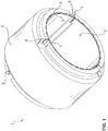
- FIG 1 shows an isometric view of a radial air bearing arrangement 1.
- the radial air bearing arrangement 1 comprises a cylindrical base support 2 with a central cylindrical recess 7.
- the base support 2 is, for example, a bearing shell or is an integral component part for example of a turbine housing of a turbocharger.
- the base support 2 is shown in detail in Figure 2 .
- a shaft (not shown) is seated in the recess 7 and is mounted by the radial air bearing arrangement 1.
- the base support 2 comprises three cutouts 6 on each of its end faces.
- Axial directions 9 pointing in opposite directions, radial directions 10 pointing in opposite directions and circumferential directions 11 pointing clockwise and counterclockwise are defined with respect to the radial air bearing arrangement 1 for the explanation of components which are arranged in relation to one another.
- the radial air bearing arrangement 1 furthermore comprises a plurality of bearing plates 3 and a plurality of spring plates 4.
- One of the spring plates 4 is shown in Figure 3 .
- Figure 4 shows one of the bearing plates 3 in detail.
- Each bearing plate 3 has two fastening tabs 5.
- the fastening tabs 5 extend in the radial direction 10.
- Spring elements 8 are formed at the ends of each of the fastening tabs 5.
- the bearing plate 3, the fastening tabs 5 and the spring elements 8 are produced together in one piece, for example as a stamped and bent part.
- Each spring plate 4 has two additional tabs 12, which likewise extend in the radial direction 10. In the assembled state as shown in Figure 1 , both the fastening tabs 5 and the additional tabs 12 each project into the cutouts 6 on the base support 2.
- the spring elements 8 are formed in such a way that they engage behind the base support 2 at a radial outer side. As a result, the spring elements 8 ensure that there is a form-fitting connection between the respective bearing plate 3 and the base support 2. As a consequence of this, the connection with the spring elements 8 can also be referred to as a latching connection. In this case, the spring element 8 accordingly represents the latching lug, which engages behind the base support 2.
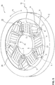
- Figure 5 shows an axial air bearing arrangement 13. Identical or functionally identical components are denoted by the same reference numerals in all of the exemplary embodiments.
- a plurality of separate bearing plates 3 and spring plates 4 are likewise provided. In each case one bearing plate 3 and one spring plate 4 form a pair with one lying on the other. The individual pairs are arranged distributed over the base support 2 along the circumferential direction 11.
- the base support 2 with the bearing plates 3 and spring plates 4 arranged thereon is configured for rotatable assembly on a counter disk (not shown).
- each spring plate 4 has two fastening tabs 5.
- the fastening tabs 5 project in the axial direction 9 into cutouts 6 (shown purely schematically) in the base support 2.
- cutouts 6 shown purely schematically
- ventilation stages 21 which have been stamped in bring about a buildup of pressure between the bearing plates 4 and the counter disk.
- Figure 6 shows the design of a spring plate 4 in detail.
- spring elements 8 are provided in turn at the end of the fastening tabs 5. These spring elements 8 are bent ends of the fastening tabs 5.
- the spring elements 8 ensure that the spring plates 4 are fixed in the cutouts 6 in the base support 2.
- the spring elements 8 can anchor in the cutouts 6 in a force-fitting manner.
- the spring elements 8 engage behind the base support 2 on an axially opposite side and therefore provide for a form-fitting connection.
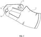
- FIG. 7 shows one of the bearing plates 3 of the second exemplary embodiment.
- Each bearing plate 3 has two further cutouts 14.
- the fastening tabs 5 are inserted not only into the cutouts 6 in the base support 2, but also into the further cutouts 14 in an adjacent bearing plate 3.
- a spring plate holding region 18 is formed on each of the spring plates 4, and a bearing plate holding region 19 is located on each bearing plate 3.
- the spring plate holding regions 18 of the spring plates 4 overlap in each case with the bearing plate holding region 19 of the bearing plates 3 of the adjacent pair. The overlapping and stable arrangement is thus formed.
- Figure 8 furthermore shows ventilation holes 17 in the bearing plates 3 and in the base support 2.
- the ventilation holes 17 in the bearing plates 3 are aligned in each case with a ventilation hole 17 in the base support 2.
- Supporting lugs 22 extending areally from the bearing plate holding regions 19 support the bearing plates 3 against twisting about the axial direction 9.
- Figure 9 shows an exemplary use for the radial air bearing arrangement 1 and the axial air bearing arrangement 13.
- Figure 9 shows a turbocharger 15 with a flanged electric machine 16.
- the rotor shaft of the electric machine 16 or the turbine shaft of the turbocharger 15 is in this case mounted by way of the radial air bearing arrangement 1 and the axial air bearing arrangement 13 as per the exemplary embodiments.
Landscapes
- Engineering & Computer Science (AREA)
- General Engineering & Computer Science (AREA)
- Mechanical Engineering (AREA)
- Physics & Mathematics (AREA)
- Fluid Mechanics (AREA)
- Supercharger (AREA)
- Structures Of Non-Positive Displacement Pumps (AREA)
- Support Of The Bearing (AREA)
Claims (12)
- Axiale Luftlageranordnung (13), aufweisend:- einen Grundträger (2) mit einer stirnseitigen Fläche (20) zur axialen Lagerung einer Welle,- mehrere auf der Fläche (20) angeordnete Lagerplatten (3), und- mehrere zwischen dem Grundträger (2) und der jeweiligen Lagerplatte (3) angeordnete Federplatten (4),wobei mehrere Paare, die jeweils aus einer der Lagerplatten (3) und aus einer der Federplatten (4) bestehen, entlang des Umfangs angeordnet sind, und
wobei die Lagerplatten (3) und die Federplatten (4) zumindest in Gruppen von zwei oder mehr benachbarten Plattenmehrteilig als separate Plattenausgeführt sind,- ferner aufweisend mindestens jeweils eine Befestigungslasche (5) an den Federplatten (4) und/oder an den Lagerplatten (3), wobei die Befestigungslasche (5) in eine Aussparung (6) im Grundträger (2) ragt,dadurch gekennzeichnet, dass an der Federplatte (4) eines ersten Paares zumindest eine Befestigungslasche (5) ausgebildet ist, wobei an der Lagerplatte (3) eines zweiten benachbarten Paares eine weitere Aussparung (14) ausgebildet ist, und wobei die Befestigungslasche (5) der Federplatte (4) des ersten Paares in der weiteren Aussparung (14) der Lagerplatte (3) des zweiten Paares steckt. - Axiale Luftlageranordnung nach Anspruch 1, wobei an zumindest einer Befestigungslasche (5) ein Federelement (8) zur Fixierung am Grundträger (2) angeordnet ist.
- Axiale Luftlageranordnung nach einem der vorhergehenden Ansprüche, wobei an zumindest einer Federplatte (4) ein Federplatten-Haltebereich (18) ausgebildet ist, und wobei an zumindest einer Lagerplatte (3) ein Lagerplatten-Haltebereich (19) ausgebildet ist, wobei der Federplatten-Haltebereich (18) der Federplatte (4) eines ersten Paares den Lagerplatten-Haltebereich (19) der Lagerplatte (3) eines zweiten Paares überlappt.
- Axiale Luftlageranordnung nach Anspruch 3, wobei die Federplatte (4) mit dem Federplatten-Haltebereich (18) den Lagerplatten-Haltebereich (19) niederdrückt.
- Axiale Luftlageranordnung nach Anspruch 2 oder nach Anspruch 2 und einem der Ansprüche 3 und 4, wobei mittels des Federelementes (8) die Befestigungslasche (5) formschlüssig mit dem Grundträger (2) verbunden ist.
- Axiale Luftlageranordnung nach Anspruch 2 oder 5 oder nach Anspruch 2 und einem der Ansprüche 3 und 4, wobei mittels des Federelementes (8) die Befestigungslasche (5) kraftschlüssig mit dem Grundträger (2) verbunden ist.
- Axiale Luftlageranordnung nach Anspruch 2, 5 oder 6 oder nach Anspruch 2 und einem der Ansprüche 3 und 4, wobei die Befestigungslasche (5) samt Federelement (8) einstückig mit der Lagerplatte (3) oder der Federplatte (4) gefertigt ist.
- Axiale Luftlageranordnung nach einem der vorhergehenden Ansprüche, aufweisend Lüftungslöcher (17) im Grundträger (2) und in zumindest einer Lagerplatte (3) und/oder in zumindest einer Federplatte (4).
- Radiale Luftlageranordnung (1), aufweisend:- einen Grundträger (2) mit einer zylindrischen Ausnehmung (7) zur radialen Lagerung einer Welle,- mehrere in der Ausnehmung (7) angeordnete Lagerplatten (3), und- mehrere zwischen dem Grundträger (2) und der jeweiligen Lagerplatte (3) angeordnete Federplatten (4),wobei die Lagerplatten (3) und die Federplatten (4) zumindest in Gruppen von zwei oder mehr benachbarten Platten mehrteilig als separate Platten ausgeführt sind,- ferner aufweisend zumindest eine Befestigungslasche (5) an zumindest einer Federplatte (4) und/oder an zumindest einer Lagerplatte (3), wobei die Befestigungslasche (5)in eine Aussparung (6) im Grundträger (2) ragt, dadurch gekennzeichnet, dass an zumindest einer Befestigungslasche (5) ein Federelement (8) zur Fixierung am Grundträger (2) angeordnet ist, und
wobei das Federelement (8) den Grundträger (2) an seiner radialen Außenseite hintergreift. - Radiale Luftlageranordnung nach Anspruch 9, wobei mittels des Federelementes (8) die Befestigungslasche (5) formschlüssig mit dem Grundträger (2) verbunden ist.
- Radiale Luftlageranordnung nach einem der Ansprüche 9 und 10, wobei mittels des Federelementes (8) die Befestigungslasche (5) kraftschlüssig mit dem Grundträger (2) verbunden ist.
- Turbolader mit einer axialen Luftlageranordnung nach einem der Ansprüche 1 bis 8 und/oder einer radialen Luftlageranordnung nach einem der Ansprüche 9 bis 11.
Applications Claiming Priority (2)
| Application Number | Priority Date | Filing Date | Title |
|---|---|---|---|
| DE102013216458 | 2013-08-20 | ||
| PCT/US2014/051269 WO2015026655A1 (en) | 2013-08-20 | 2014-08-15 | Air bearing arrangement |
Publications (3)
| Publication Number | Publication Date |
|---|---|
| EP3036409A1 EP3036409A1 (de) | 2016-06-29 |
| EP3036409A4 EP3036409A4 (de) | 2017-04-19 |
| EP3036409B1 true EP3036409B1 (de) | 2018-10-24 |
Family
ID=52484064
Family Applications (1)
| Application Number | Title | Priority Date | Filing Date |
|---|---|---|---|
| EP14838594.1A Active EP3036409B1 (de) | 2013-08-20 | 2014-08-15 | Luftlageranordnung |
Country Status (4)
| Country | Link |
|---|---|
| EP (1) | EP3036409B1 (de) |
| JP (1) | JP6698018B2 (de) |
| KR (1) | KR102216550B1 (de) |
| WO (1) | WO2015026655A1 (de) |
Cited By (1)
| Publication number | Priority date | Publication date | Assignee | Title |
|---|---|---|---|---|
| WO2024074167A1 (de) * | 2022-10-07 | 2024-04-11 | Schaeffler Technologies AG & Co. KG | RADIALFOLIENLAGER - BEFESTIGUNG DER WELL- UND DECKFOLIEN IM AUßENRING MITTELS GEBOGENER HAKEN |
Families Citing this family (5)
| Publication number | Priority date | Publication date | Assignee | Title |
|---|---|---|---|---|
| WO2017169676A1 (ja) * | 2016-03-30 | 2017-10-05 | Ntn株式会社 | フォイル軸受 |
| JP7230927B2 (ja) | 2019-01-17 | 2023-03-01 | 株式会社Ihi | スラストフォイル軸受 |
| EP3931454B8 (de) * | 2019-03-22 | 2023-07-12 | Bladon Jets Holdings Limited | Nachgiebiges folienradiallager |
| DE102022125923A1 (de) * | 2022-10-07 | 2024-04-18 | Schaeffler Technologies AG & Co. KG | Radialfolienlager mit Trägerfolie - Befestigung der Folienpakete auf der Trägerfolie mittels gebogener Haken |
| CN117450167B (zh) * | 2023-12-20 | 2024-03-12 | 山东华东风机有限公司 | 一种轴向箔片空气止推轴承及空压机 |
Family Cites Families (15)
| Publication number | Priority date | Publication date | Assignee | Title |
|---|---|---|---|---|
| US4552466A (en) * | 1984-04-24 | 1985-11-12 | The United States Of America As Represented By The Administrator Of The National Aeronautics And Space Administration | Compliant hydrodynamic fluid journal bearing |
| JPS6132532U (ja) * | 1984-07-30 | 1986-02-27 | 日本精工株式会社 | 過給機の軸受装置 |
| JPS6184415A (ja) * | 1984-10-03 | 1986-04-30 | Ishikawajima Harima Heavy Ind Co Ltd | 軸シ−ル付フオイル軸受構造 |
| US4795274A (en) * | 1987-08-10 | 1989-01-03 | Allied-Signal Inc. | Foil bearing |
| JPH0742980B2 (ja) * | 1988-03-22 | 1995-05-15 | 石川島播磨重工業株式会社 | 動圧スラスト流体軸受 |
| US5427455A (en) * | 1994-04-18 | 1995-06-27 | Bosley; Robert W. | Compliant foil hydrodynamic fluid film radial bearing |
| US5658079A (en) * | 1995-06-05 | 1997-08-19 | United Technologies Corporation | Hydrodynamic fluid film journal bearing |
| US5871284A (en) * | 1997-09-10 | 1999-02-16 | Alliedsignal Inc. | Foil thrust bearing set |
| KR100360240B1 (ko) | 1999-12-24 | 2002-11-08 | 엘지전자 주식회사 | 포일 스러스트 베어링 구조 |
| JP3463026B2 (ja) * | 2000-08-24 | 2003-11-05 | 川崎重工業株式会社 | 動圧型空気軸受 |
| US7648280B2 (en) * | 2007-04-12 | 2010-01-19 | Hamilton Sundstrand Corporation | Weight reduction for journal air bearing |
| US8029194B2 (en) * | 2007-06-18 | 2011-10-04 | R&D Dynamics Corporation | Restrained, reverse multi-pad bearing assembly |
| JP4973590B2 (ja) * | 2008-04-30 | 2012-07-11 | 株式会社島津製作所 | 動圧気体軸受 |
| KR101375184B1 (ko) * | 2009-02-20 | 2014-03-17 | 삼성테크윈 주식회사 | 공기 포일 베어링 |
| KR102077148B1 (ko) * | 2011-08-24 | 2020-02-14 | 보르그워너 인코퍼레이티드 | 베어링 장치 |
-
2014
- 2014-08-15 JP JP2016536336A patent/JP6698018B2/ja active Active
- 2014-08-15 WO PCT/US2014/051269 patent/WO2015026655A1/en active Application Filing
- 2014-08-15 KR KR1020167005995A patent/KR102216550B1/ko active IP Right Grant
- 2014-08-15 EP EP14838594.1A patent/EP3036409B1/de active Active
Cited By (1)
| Publication number | Priority date | Publication date | Assignee | Title |
|---|---|---|---|---|
| WO2024074167A1 (de) * | 2022-10-07 | 2024-04-11 | Schaeffler Technologies AG & Co. KG | RADIALFOLIENLAGER - BEFESTIGUNG DER WELL- UND DECKFOLIEN IM AUßENRING MITTELS GEBOGENER HAKEN |
Also Published As
| Publication number | Publication date |
|---|---|
| EP3036409A1 (de) | 2016-06-29 |
| KR20160043978A (ko) | 2016-04-22 |
| KR102216550B1 (ko) | 2021-02-17 |
| JP6698018B2 (ja) | 2020-05-27 |
| JP2016531256A (ja) | 2016-10-06 |
| WO2015026655A1 (en) | 2015-02-26 |
| EP3036409A4 (de) | 2017-04-19 |
Similar Documents
| Publication | Publication Date | Title |
|---|---|---|
| EP3036409B1 (de) | Luftlageranordnung | |
| JP5685506B2 (ja) | 回転電機の回転子、回転電機および回転子の端面部材 | |
| US8587895B1 (en) | Bearing mechanism, motor and disk drive apparatus | |
| US8223455B2 (en) | Rotor hub, motor, and disk driving device | |
| US20130004304A1 (en) | Fan | |
| JP2010286071A (ja) | 軸受装置、スピンドルモータ、及びディスク駆動装置 | |
| CN108368874B (zh) | 膜轴承 | |
| JP5363425B2 (ja) | 電気機械のロータおよびその製造方法 | |
| JP2009247143A (ja) | ファンモータ | |
| CN107407386B (zh) | 用于流体动力止推轴承的轴向保持和防转动结构 | |
| KR20160078090A (ko) | 틸팅 패드 스러스트 베어링 및 틸팅 패드 스러스트 베어링 조립체 | |
| JP7152596B2 (ja) | 風力タービンのロータのベアリングアセンブリ | |
| KR20220027205A (ko) | 유연성 포일 추력 베어링 | |
| JP2009243381A (ja) | ファンモータ | |
| JP5259249B2 (ja) | ロータ及びモータ | |
| JP5970020B2 (ja) | タービンのブレード | |
| JP6559961B2 (ja) | モータ | |
| JP2017500503A (ja) | 遊星歯車機構の遊星軸受における軸方向の固定装置 | |
| CN103620917A (zh) | 电动马达的转子 | |
| US6945696B2 (en) | Hydrodynamic thrust bearing | |
| JP2020026807A (ja) | ベアリング構造 | |
| KR100971302B1 (ko) | 디스크 척킹 장치 | |
| US20150085398A1 (en) | Spindle motor and disk drive apparatus | |
| JP2019122086A (ja) | モータ及びファン | |
| CN115769472A (zh) | 端板 |
Legal Events
| Date | Code | Title | Description |
|---|---|---|---|
| PUAI | Public reference made under article 153(3) epc to a published international application that has entered the european phase |
Free format text: ORIGINAL CODE: 0009012 |
|
| 17P | Request for examination filed |
Effective date: 20160308 |
|
| AK | Designated contracting states |
Kind code of ref document: A1 Designated state(s): AL AT BE BG CH CY CZ DE DK EE ES FI FR GB GR HR HU IE IS IT LI LT LU LV MC MK MT NL NO PL PT RO RS SE SI SK SM TR |
|
| AX | Request for extension of the european patent |
Extension state: BA ME |
|
| DAX | Request for extension of the european patent (deleted) | ||
| A4 | Supplementary search report drawn up and despatched |
Effective date: 20170320 |
|
| RIC1 | Information provided on ipc code assigned before grant |
Ipc: F16C 43/02 20060101ALI20170314BHEP Ipc: F16C 37/00 20060101ALN20170314BHEP Ipc: F16C 35/02 20060101ALI20170314BHEP Ipc: F01D 25/16 20060101AFI20170314BHEP Ipc: F16C 32/06 20060101ALI20170314BHEP |
|
| RIC1 | Information provided on ipc code assigned before grant |
Ipc: F16C 43/02 20060101ALI20180315BHEP Ipc: F16C 35/02 20060101ALI20180315BHEP Ipc: F16C 37/00 20060101ALN20180315BHEP Ipc: F01D 25/16 20060101AFI20180315BHEP Ipc: F16C 32/06 20060101ALI20180315BHEP |
|
| RIC1 | Information provided on ipc code assigned before grant |
Ipc: F16C 32/06 20060101ALI20180322BHEP Ipc: F16C 35/02 20060101ALI20180322BHEP Ipc: F16C 37/00 20060101ALN20180322BHEP Ipc: F16C 43/02 20060101ALI20180322BHEP Ipc: F01D 25/16 20060101AFI20180322BHEP |
|
| GRAP | Despatch of communication of intention to grant a patent |
Free format text: ORIGINAL CODE: EPIDOSNIGR1 |
|
| STAA | Information on the status of an ep patent application or granted ep patent |
Free format text: STATUS: GRANT OF PATENT IS INTENDED |
|
| INTG | Intention to grant announced |
Effective date: 20180430 |
|
| GRAJ | Information related to disapproval of communication of intention to grant by the applicant or resumption of examination proceedings by the epo deleted |
Free format text: ORIGINAL CODE: EPIDOSDIGR1 |
|
| STAA | Information on the status of an ep patent application or granted ep patent |
Free format text: STATUS: REQUEST FOR EXAMINATION WAS MADE |
|
| GRAP | Despatch of communication of intention to grant a patent |
Free format text: ORIGINAL CODE: EPIDOSNIGR1 |
|
| STAA | Information on the status of an ep patent application or granted ep patent |
Free format text: STATUS: GRANT OF PATENT IS INTENDED |
|
| GRAS | Grant fee paid |
Free format text: ORIGINAL CODE: EPIDOSNIGR3 |
|
| GRAA | (expected) grant |
Free format text: ORIGINAL CODE: 0009210 |
|
| STAA | Information on the status of an ep patent application or granted ep patent |
Free format text: STATUS: THE PATENT HAS BEEN GRANTED |
|
| INTC | Intention to grant announced (deleted) | ||
| RIC1 | Information provided on ipc code assigned before grant |
Ipc: F16C 35/02 20060101ALI20180828BHEP Ipc: F16C 32/06 20060101ALI20180828BHEP Ipc: F16C 43/02 20060101ALI20180828BHEP Ipc: F01D 25/16 20060101AFI20180828BHEP Ipc: F16C 37/00 20060101ALN20180828BHEP |
|
| INTG | Intention to grant announced |
Effective date: 20180910 |
|
| AK | Designated contracting states |
Kind code of ref document: B1 Designated state(s): AL AT BE BG CH CY CZ DE DK EE ES FI FR GB GR HR HU IE IS IT LI LT LU LV MC MK MT NL NO PL PT RO RS SE SI SK SM TR |
|
| REG | Reference to a national code |
Ref country code: CH Ref legal event code: EP |
|
| REG | Reference to a national code |
Ref country code: IE Ref legal event code: FG4D |
|
| REG | Reference to a national code |
Ref country code: AT Ref legal event code: REF Ref document number: 1056907 Country of ref document: AT Kind code of ref document: T Effective date: 20181115 |
|
| REG | Reference to a national code |
Ref country code: DE Ref legal event code: R096 Ref document number: 602014034815 Country of ref document: DE |
|
| REG | Reference to a national code |
Ref country code: NL Ref legal event code: FP |
|
| REG | Reference to a national code |
Ref country code: LT Ref legal event code: MG4D |
|
| REG | Reference to a national code |
Ref country code: AT Ref legal event code: MK05 Ref document number: 1056907 Country of ref document: AT Kind code of ref document: T Effective date: 20181024 |
|
| PG25 | Lapsed in a contracting state [announced via postgrant information from national office to epo] |
Ref country code: FI Free format text: LAPSE BECAUSE OF FAILURE TO SUBMIT A TRANSLATION OF THE DESCRIPTION OR TO PAY THE FEE WITHIN THE PRESCRIBED TIME-LIMIT Effective date: 20181024 Ref country code: HR Free format text: LAPSE BECAUSE OF FAILURE TO SUBMIT A TRANSLATION OF THE DESCRIPTION OR TO PAY THE FEE WITHIN THE PRESCRIBED TIME-LIMIT Effective date: 20181024 Ref country code: PL Free format text: LAPSE BECAUSE OF FAILURE TO SUBMIT A TRANSLATION OF THE DESCRIPTION OR TO PAY THE FEE WITHIN THE PRESCRIBED TIME-LIMIT Effective date: 20181024 Ref country code: LT Free format text: LAPSE BECAUSE OF FAILURE TO SUBMIT A TRANSLATION OF THE DESCRIPTION OR TO PAY THE FEE WITHIN THE PRESCRIBED TIME-LIMIT Effective date: 20181024 Ref country code: AT Free format text: LAPSE BECAUSE OF FAILURE TO SUBMIT A TRANSLATION OF THE DESCRIPTION OR TO PAY THE FEE WITHIN THE PRESCRIBED TIME-LIMIT Effective date: 20181024 Ref country code: LV Free format text: LAPSE BECAUSE OF FAILURE TO SUBMIT A TRANSLATION OF THE DESCRIPTION OR TO PAY THE FEE WITHIN THE PRESCRIBED TIME-LIMIT Effective date: 20181024 Ref country code: NO Free format text: LAPSE BECAUSE OF FAILURE TO SUBMIT A TRANSLATION OF THE DESCRIPTION OR TO PAY THE FEE WITHIN THE PRESCRIBED TIME-LIMIT Effective date: 20190124 Ref country code: IS Free format text: LAPSE BECAUSE OF FAILURE TO SUBMIT A TRANSLATION OF THE DESCRIPTION OR TO PAY THE FEE WITHIN THE PRESCRIBED TIME-LIMIT Effective date: 20190224 Ref country code: ES Free format text: LAPSE BECAUSE OF FAILURE TO SUBMIT A TRANSLATION OF THE DESCRIPTION OR TO PAY THE FEE WITHIN THE PRESCRIBED TIME-LIMIT Effective date: 20181024 Ref country code: BG Free format text: LAPSE BECAUSE OF FAILURE TO SUBMIT A TRANSLATION OF THE DESCRIPTION OR TO PAY THE FEE WITHIN THE PRESCRIBED TIME-LIMIT Effective date: 20190124 |
|
| PG25 | Lapsed in a contracting state [announced via postgrant information from national office to epo] |
Ref country code: SE Free format text: LAPSE BECAUSE OF FAILURE TO SUBMIT A TRANSLATION OF THE DESCRIPTION OR TO PAY THE FEE WITHIN THE PRESCRIBED TIME-LIMIT Effective date: 20181024 Ref country code: PT Free format text: LAPSE BECAUSE OF FAILURE TO SUBMIT A TRANSLATION OF THE DESCRIPTION OR TO PAY THE FEE WITHIN THE PRESCRIBED TIME-LIMIT Effective date: 20190224 Ref country code: AL Free format text: LAPSE BECAUSE OF FAILURE TO SUBMIT A TRANSLATION OF THE DESCRIPTION OR TO PAY THE FEE WITHIN THE PRESCRIBED TIME-LIMIT Effective date: 20181024 Ref country code: GR Free format text: LAPSE BECAUSE OF FAILURE TO SUBMIT A TRANSLATION OF THE DESCRIPTION OR TO PAY THE FEE WITHIN THE PRESCRIBED TIME-LIMIT Effective date: 20190125 Ref country code: RS Free format text: LAPSE BECAUSE OF FAILURE TO SUBMIT A TRANSLATION OF THE DESCRIPTION OR TO PAY THE FEE WITHIN THE PRESCRIBED TIME-LIMIT Effective date: 20181024 |
|
| REG | Reference to a national code |
Ref country code: DE Ref legal event code: R097 Ref document number: 602014034815 Country of ref document: DE |
|
| PG25 | Lapsed in a contracting state [announced via postgrant information from national office to epo] |
Ref country code: CZ Free format text: LAPSE BECAUSE OF FAILURE TO SUBMIT A TRANSLATION OF THE DESCRIPTION OR TO PAY THE FEE WITHIN THE PRESCRIBED TIME-LIMIT Effective date: 20181024 Ref country code: DK Free format text: LAPSE BECAUSE OF FAILURE TO SUBMIT A TRANSLATION OF THE DESCRIPTION OR TO PAY THE FEE WITHIN THE PRESCRIBED TIME-LIMIT Effective date: 20181024 |
|
| PG25 | Lapsed in a contracting state [announced via postgrant information from national office to epo] |
Ref country code: SM Free format text: LAPSE BECAUSE OF FAILURE TO SUBMIT A TRANSLATION OF THE DESCRIPTION OR TO PAY THE FEE WITHIN THE PRESCRIBED TIME-LIMIT Effective date: 20181024 Ref country code: EE Free format text: LAPSE BECAUSE OF FAILURE TO SUBMIT A TRANSLATION OF THE DESCRIPTION OR TO PAY THE FEE WITHIN THE PRESCRIBED TIME-LIMIT Effective date: 20181024 Ref country code: RO Free format text: LAPSE BECAUSE OF FAILURE TO SUBMIT A TRANSLATION OF THE DESCRIPTION OR TO PAY THE FEE WITHIN THE PRESCRIBED TIME-LIMIT Effective date: 20181024 Ref country code: SK Free format text: LAPSE BECAUSE OF FAILURE TO SUBMIT A TRANSLATION OF THE DESCRIPTION OR TO PAY THE FEE WITHIN THE PRESCRIBED TIME-LIMIT Effective date: 20181024 |
|
| PLBE | No opposition filed within time limit |
Free format text: ORIGINAL CODE: 0009261 |
|
| STAA | Information on the status of an ep patent application or granted ep patent |
Free format text: STATUS: NO OPPOSITION FILED WITHIN TIME LIMIT |
|
| 26N | No opposition filed |
Effective date: 20190725 |
|
| PG25 | Lapsed in a contracting state [announced via postgrant information from national office to epo] |
Ref country code: SI Free format text: LAPSE BECAUSE OF FAILURE TO SUBMIT A TRANSLATION OF THE DESCRIPTION OR TO PAY THE FEE WITHIN THE PRESCRIBED TIME-LIMIT Effective date: 20181024 |
|
| PG25 | Lapsed in a contracting state [announced via postgrant information from national office to epo] |
Ref country code: TR Free format text: LAPSE BECAUSE OF FAILURE TO SUBMIT A TRANSLATION OF THE DESCRIPTION OR TO PAY THE FEE WITHIN THE PRESCRIBED TIME-LIMIT Effective date: 20181024 |
|
| PG25 | Lapsed in a contracting state [announced via postgrant information from national office to epo] |
Ref country code: CH Free format text: LAPSE BECAUSE OF NON-PAYMENT OF DUE FEES Effective date: 20190831 Ref country code: LI Free format text: LAPSE BECAUSE OF NON-PAYMENT OF DUE FEES Effective date: 20190831 Ref country code: LU Free format text: LAPSE BECAUSE OF NON-PAYMENT OF DUE FEES Effective date: 20190815 Ref country code: MC Free format text: LAPSE BECAUSE OF FAILURE TO SUBMIT A TRANSLATION OF THE DESCRIPTION OR TO PAY THE FEE WITHIN THE PRESCRIBED TIME-LIMIT Effective date: 20181024 |
|
| REG | Reference to a national code |
Ref country code: BE Ref legal event code: MM Effective date: 20190831 |
|
| PG25 | Lapsed in a contracting state [announced via postgrant information from national office to epo] |
Ref country code: IE Free format text: LAPSE BECAUSE OF NON-PAYMENT OF DUE FEES Effective date: 20190815 |
|
| PG25 | Lapsed in a contracting state [announced via postgrant information from national office to epo] |
Ref country code: BE Free format text: LAPSE BECAUSE OF NON-PAYMENT OF DUE FEES Effective date: 20190831 |
|
| PG25 | Lapsed in a contracting state [announced via postgrant information from national office to epo] |
Ref country code: CY Free format text: LAPSE BECAUSE OF FAILURE TO SUBMIT A TRANSLATION OF THE DESCRIPTION OR TO PAY THE FEE WITHIN THE PRESCRIBED TIME-LIMIT Effective date: 20181024 |
|
| PG25 | Lapsed in a contracting state [announced via postgrant information from national office to epo] |
Ref country code: HU Free format text: LAPSE BECAUSE OF FAILURE TO SUBMIT A TRANSLATION OF THE DESCRIPTION OR TO PAY THE FEE WITHIN THE PRESCRIBED TIME-LIMIT; INVALID AB INITIO Effective date: 20140815 Ref country code: MT Free format text: LAPSE BECAUSE OF FAILURE TO SUBMIT A TRANSLATION OF THE DESCRIPTION OR TO PAY THE FEE WITHIN THE PRESCRIBED TIME-LIMIT Effective date: 20181024 |
|
| PG25 | Lapsed in a contracting state [announced via postgrant information from national office to epo] |
Ref country code: MK Free format text: LAPSE BECAUSE OF FAILURE TO SUBMIT A TRANSLATION OF THE DESCRIPTION OR TO PAY THE FEE WITHIN THE PRESCRIBED TIME-LIMIT Effective date: 20181024 |
|
| P01 | Opt-out of the competence of the unified patent court (upc) registered |
Effective date: 20230327 |
|
| PGFP | Annual fee paid to national office [announced via postgrant information from national office to epo] |
Ref country code: NL Payment date: 20230720 Year of fee payment: 10 |
|
| PGFP | Annual fee paid to national office [announced via postgrant information from national office to epo] |
Ref country code: IT Payment date: 20230810 Year of fee payment: 10 Ref country code: GB Payment date: 20230712 Year of fee payment: 10 |
|
| PGFP | Annual fee paid to national office [announced via postgrant information from national office to epo] |
Ref country code: FR Payment date: 20230710 Year of fee payment: 10 Ref country code: DE Payment date: 20230711 Year of fee payment: 10 |