EP3035551B1 - Method and device for the self-test of the measurement precision of an electricity meter - Google Patents
Method and device for the self-test of the measurement precision of an electricity meter Download PDFInfo
- Publication number
- EP3035551B1 EP3035551B1 EP15201719.0A EP15201719A EP3035551B1 EP 3035551 B1 EP3035551 B1 EP 3035551B1 EP 15201719 A EP15201719 A EP 15201719A EP 3035551 B1 EP3035551 B1 EP 3035551B1
- Authority
- EP
- European Patent Office
- Prior art keywords
- power
- electricity meter
- values
- modulatable
- switch
- Prior art date
- Legal status (The legal status is an assumption and is not a legal conclusion. Google has not performed a legal analysis and makes no representation as to the accuracy of the status listed.)
- Active
Links
- 230000005611 electricity Effects 0.000 title claims description 51
- 238000012360 testing method Methods 0.000 title claims description 36
- 238000000034 method Methods 0.000 title claims description 25
- 238000005259 measurement Methods 0.000 title description 9
- 238000009499 grossing Methods 0.000 claims description 11
- 230000007246 mechanism Effects 0.000 claims description 5
- 239000003990 capacitor Substances 0.000 description 23
- 230000005540 biological transmission Effects 0.000 description 17
- 238000004891 communication Methods 0.000 description 15
- 230000000694 effects Effects 0.000 description 14
- 238000010616 electrical installation Methods 0.000 description 13
- 230000008569 process Effects 0.000 description 7
- 230000032683 aging Effects 0.000 description 4
- 230000004913 activation Effects 0.000 description 3
- 238000013461 design Methods 0.000 description 3
- 238000009434 installation Methods 0.000 description 3
- 230000008901 benefit Effects 0.000 description 2
- 238000004364 calculation method Methods 0.000 description 2
- 238000007796 conventional method Methods 0.000 description 2
- 238000010219 correlation analysis Methods 0.000 description 2
- 230000008878 coupling Effects 0.000 description 2
- 238000010168 coupling process Methods 0.000 description 2
- 238000005859 coupling reaction Methods 0.000 description 2
- 230000002349 favourable effect Effects 0.000 description 2
- 230000007935 neutral effect Effects 0.000 description 2
- 238000003909 pattern recognition Methods 0.000 description 2
- 238000012546 transfer Methods 0.000 description 2
- 240000003517 Elaeocarpus dentatus Species 0.000 description 1
- 241000196324 Embryophyta Species 0.000 description 1
- 235000014676 Phragmites communis Nutrition 0.000 description 1
- 230000005856 abnormality Effects 0.000 description 1
- 230000033228 biological regulation Effects 0.000 description 1
- 230000001413 cellular effect Effects 0.000 description 1
- 239000003985 ceramic capacitor Substances 0.000 description 1
- 230000008859 change Effects 0.000 description 1
- 238000010276 construction Methods 0.000 description 1
- 230000007423 decrease Effects 0.000 description 1
- 238000005516 engineering process Methods 0.000 description 1
- 238000010438 heat treatment Methods 0.000 description 1
- 230000006872 improvement Effects 0.000 description 1
- 230000002452 interceptive effect Effects 0.000 description 1
- 238000012544 monitoring process Methods 0.000 description 1
- 230000001105 regulatory effect Effects 0.000 description 1
- 230000004044 response Effects 0.000 description 1
- 230000000630 rising effect Effects 0.000 description 1
- 239000004065 semiconductor Substances 0.000 description 1
- 230000001360 synchronised effect Effects 0.000 description 1
- XLYOFNOQVPJJNP-UHFFFAOYSA-N water Substances O XLYOFNOQVPJJNP-UHFFFAOYSA-N 0.000 description 1
- 238000003466 welding Methods 0.000 description 1
Images


Classifications
-
- H—ELECTRICITY
- H04—ELECTRIC COMMUNICATION TECHNIQUE
- H04B—TRANSMISSION
- H04B3/00—Line transmission systems
- H04B3/54—Systems for transmission via power distribution lines
-
- G—PHYSICS
- G01—MEASURING; TESTING
- G01R—MEASURING ELECTRIC VARIABLES; MEASURING MAGNETIC VARIABLES
- G01R22/00—Arrangements for measuring time integral of electric power or current, e.g. electricity meters
- G01R22/06—Arrangements for measuring time integral of electric power or current, e.g. electricity meters by electronic methods
- G01R22/061—Details of electronic electricity meters
- G01R22/063—Details of electronic electricity meters related to remote communication
-
- G—PHYSICS
- G01—MEASURING; TESTING
- G01R—MEASURING ELECTRIC VARIABLES; MEASURING MAGNETIC VARIABLES
- G01R35/00—Testing or calibrating of apparatus covered by the other groups of this subclass
- G01R35/04—Testing or calibrating of apparatus covered by the other groups of this subclass of instruments for measuring time integral of power or current
Landscapes
- Engineering & Computer Science (AREA)
- Power Engineering (AREA)
- Computer Networks & Wireless Communication (AREA)
- Signal Processing (AREA)
- Arrangements For Transmission Of Measured Signals (AREA)
Description
Zur Übertragung von Daten über vorhandene Stromnetze sind verschiedenste Verfahren und Vorrichtungen bekannt, für die im Folgenden der geläufige Oberbegriff Powerline Communication (PLC) verwendet werden soll. Bei üblichen Verfahren entnehmen Sendeeinrichtungen dem Stromnetz bei der Nennfrequenz Leistung, und speisen bei einer von der Nennfrequenz des Stromnetzes abweichenden Frequenz, meist bei höheren Frequenzen bzw. in höheren Frequenzbändern, Leistung in das Stromnetz ein. Aus
Gemeinsamer Nachteil der bekannten PLC Verfahren ist, dass eine dedizierte Empfangseinrichtung benötigt wird. Auch in Anwendungen im Zusammenhang mit fernauslesbaren Elektrizitätszählern wird eine dedizierte Empfangseinrichtung benötigt. Dies gilt selbst dann, wenn Elektrizitätszähler und Empfangseinrichtung einstückig hergestellt sind, um Spareffekte bei Gehäuse, Netzteil und Montage zu erzielen. Beispielhaft sei
Ein weiterer gemeinsamer Nachteil der bekannten PLC Verfahren ist, dass vorhandene Stromnetze dazu ausgelegt sind, elektrische Energie mit Netzfrequenz zu übertragen. Sie sind jedoch nicht dazu ausgelegt, elektrische Energie mit Vielfachen oder Bruchteilen der Netzfrequenz zu übertragen. Zudem können übliche Verbraucher Störsignale erzeugen, die so groß sind, dass während der Aktivität dieser Verbraucher die Kommunikation mit bekannten PLC Verfahren zum Erliegen kommt. Es gibt zwar Regulierungen wie z.B. die Norm DIN EN 50065-1 und Frequenzzuweisungen, die beispielsweise das sogenannte "CENELEC-A Band" ausschließlich für metering-Anwendungen reservieren, aber diese Norm reguliert lediglich die Erzeugung von Nutz- und Störsignalen durch für Kommunikationszwecke vorgesehene Geräte (also für PLC-Geräte), sie trifft keine Aussagen über die Erzeugung von Störsignalen durch Verbraucher, die nicht der Kommunikation über Stromnetze dienen, wie beispielsweise Motoren, Elektroschweißgeräte, oder Ladegeräte für Mobiltelefone. Aus diesem Grunde bedingt die Kommunikation per PLC mehr Unwägbarkeiten als andere Verfahren zur Datenübertragung.Another common disadvantage of the known PLC method is that existing power grids are designed to transmit electrical power at mains frequency. However, they are not designed to transmit electrical energy at multiples or fractions of the line frequency. In addition, conventional consumers may generate spurious signals that are so large that during the activity of these consumers communication with known PLC methods comes to a standstill. Although there are regulations such as the standard DIN EN 50065-1 and frequency allocations that reserve, for example, the so-called "CENELEC-A band" exclusively for metering applications, but this standard regulates only the generation of useful and interfering signals by equipment intended for communication purposes (ie for PLC devices), she makes no statements about the Generation of interference signals by consumers who do not serve communication via power grids, such as motors, electric welding equipment, or chargers for mobile phones. For this reason, communication via the PLC requires more imponderables than other methods of data transmission.
Aus der Druckschrift
Aus der Druckschrift
Aus der Druckschrift
Aufgabe der vorliegenden Erfindung ist es, ein Verfahren und eine Vorrichtung für einen Selbsttest der Messgenauigkeit eines Elektrizitätszählers zur Verfügung zu stellen.The object of the present invention is to provide a method and a device for a self-test of the measurement accuracy of an electricity meter.
Die Aufgabe wird gelöst durch das Verfahren mit den Merkmalen des Anspruchs 1 und eine Vorrichtung mit den Merkmalen des Anspruchs 2. Vorteilhafte Ausgestaltungen sind in den Unteransprüchen angegeben.The object is achieved by the method having the features of
Kurzbeschreibung der Figuren:
-
Figur 1 -
Figur 2Figur 2 -
Figur 3Figur 3 -
Figur 4 zeigt ein Gerät, das Daten sendet, indem es einen Blindverbrauch moduliert. -
Figur 5 -
Figur 6a-d zeigt beispielhaft einige Beispiele unterscheidbarer Signale, die jeweils unterschiedliche Daten repräsentieren können. -
Figur 7 zeigt ein Gerät, das dazu ausgebildet ist, erste Daten zu senden, die ein Aktivieren eines ersten Schalters repräsentieren, und das dazu ausgebildet ist, zweite Daten zu senden, die ein Aktivieren eines zweiten Schalters repräsentieren. -
Figur 8 zeigt eine Vorrichtung zur Übertragung einer Prüfleistung über ein vorhandenes Stromnetz, die einen Wirkverbrauch moduliert und die einen Elektrizitätszähler, der die Modulation des Verbrauchs im Stromnetz erfasst, auf korrekte Funktion seines Messwerks überprüft. -
Figur 9 zeigt einen Elektrizitätszähler, der dazu ausgebildet ist, seine Messwerke automatisch zu testen. -
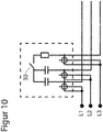
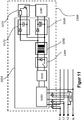
Figur 10 -
Figur 11 zeigt einen Elektrizitätszähler, der zum automatischen Test seiner Messwerke einen Referenzverbraucher enthält.
-
FIG. 1 shows a device for transmitting data over an existing power network with a television that transmits data by modulating active consumption, and an electricity meter that detects the active power consumption and reconstructs the modulated data. -
FIG. 2 shows an electricity meter with a measuring unit of simple design.FIG. 2 clarifies that no dedicated receiving circuits are needed in the electricity meter for the transmission of data and no special requirements are placed on the meter of the electricity meter. -
FIG. 3 shows a device with a simple electricity meter and a remote meter reading gateway.FIG. 3 makes it clear that no special electricity meters are needed, but that commercial electricity meters can act as receivers. -
FIG. 4 shows a device that sends data by modulating a blind consumption. -
FIG. 5 shows a device that sends data by storing energy beyond a network period. -
Figure 6a-d shows by way of example some examples of distinguishable signals, each of which can represent different data. -
FIG. 7 shows a device configured to transmit first data representing activation of a first switch and configured to transmit second data representing activation of a second switch. -
FIG. 8 shows a device for transmitting a test power over an existing power grid, which modulates an active consumption and checks an electricity meter, which detects the modulation of consumption in the power grid, for correct operation of his measuring unit. -
FIG. 9 shows an electricity meter, which is designed to test its measuring devices automatically. -
FIG. 10 shows a cost-optimized electricity meter, which is designed to test its measuring devices automatically. -
FIG. 11 shows an electricity meter, which contains a reference consumer for the automatic test of his measuring plants.
Ausführliche Beschreibung der in den Figuren gezeigten Ausführungsbeispiele:
Das Kommunikationsgerät 120 ist dazu vorgesehen, Zählerstände zwecks Rechnungslegung an einen Energieversorger zu übermitteln. Das Kommunikationsgerät 120 ist weiterhin dazu vorgesehen, aus Mustern im Stromverbrauch auf Notfälle zu schließen, und in Notfällen Alarmmeldungen zu senden. Dabei wird aus Benutzereingaben an der Fernbedienung 40 respektive Bedienknöpfen 50 auf eine Benutzeraktivität geschlossen. Der Wasserkocher 70 ist einfachster Bauart, weist keine eigene Steuerung auf, sondern lediglich einen Heizwiderstand mit positivem Temperaturkoeffizienten. Ein Einschalten des Wasserkochers bewirkt einen markanten Sprung der im Elektrizitätszähler 110 gemessenen Wirkleistung, gefolgt von einem exponentiellen Abklingen. Mit bekannten Verfahren der Mustererkennung kann aus den Messwerten der Wirkleistung auf die Benutzeraktivität "Wasser kochen" geschlossen werden und im Falle von Auffälligkeiten kann ein Alarm über das Kommunikationsgerät 120 abgesetzt werden.The
Im Falle des Fernsehgeräts 10 stellt sich die Situation gegensätzlich dar. Es hat sich gezeigt, dass bei üblichen Fernsehgeräten die aufgenommene Wirkleistung sehr stark von den dargestellten Bildinhalten (Helligkeits schwankungen) abhängt, und sehr wenig von Benutzereingaben. Um dennoch einen Rückschluss von Messwerten der Wirkleistung auf die Benutzeraktivität zu ermöglichen, weist das Fernsehgerät 10 eine Steuerung 60 auf, die dazu ausgebildet ist, in einem definierten Zeitraum von beispielsweise 2 Minuten nach einer Benutzereingabe den Schalter 30 mit einem definierten Muster anzusteuern, und so den Leistungsfluss vom Elektrizitätszähler 110 zum Fernsehgerät 10 zu modulieren. Diese Modulation wird im Elektrizitätszähler 110 erfasst, und so auf die Benutzeraktivität geschlossen. Der Wirkverbraucher 20 ist in diesem Ausführungsbeispiel ein für die Erzeugung des Fernsehbildes notwendiger Verbraucher, und zwar beispielsweise ein Recheneinheit, die in komprimierter Form übertragene Bilddaten dekomprimiert. Diese Recheneinheit weist einen Energiesparmodus auf, in dem sie keine Berechnungen ausführt, und einen Rechenmodus, in dem Sie Bilddaten mit doppelter Geschwindigkeit dekomprimiert. Der Schalter 30 verkörpert also die Umschaltung zwischen Energiesparmodus und Rechenmodus. Die Steuerung 60 weist nach einer Benutzeraktivität die Recheneinheit an, mit doppelter Geschwindigkeit Bilddaten zu verarbeiten. Die dabei auf Vorrat produzierten Bilddaten werden in einem geeigneten Puffer gespeichert. Nach beispielsweise 10 Sekunden weist die Steuerung 60 die Recheneinheit an, einen Energiesparmodus anzunehmen. Die auf Vorrat produzierten Bilddaten werden dann dem genannten Puffer entnommen. Nach weiteren 10 Sekunden weist die Steuerung 60 die Recheneinheit an, wieder mit doppelter Geschwindigkeit Bilddaten zu verarbeiten, und so fort, bis nach zwei Minuten ohne weitere Benutzereingabe die Steuerung 60 die Recheneinheit anweist, mit einfacher Geschwindigkeit Bilddaten zu verarbeiten, und somit die Modulation zu beenden. Für das Senden wird also keine zusätzliche Sendeleistung aufgewendet, es werden lediglich die Zeitpunkte sowieso erforderlicher Rechenoperationen verlagert. Die resultierende Latenz von 10 Sekunden kann sich störend auswirken. Deshalb kann die erfindungsgemäße Übertragung von Daten über das Stromnetz über einen Bedienknopf 50 komplett deaktiviert werden, so dass ein nicht überwachungsbedürftiger Benutzer ein Tor in einer Live-Fußballübertragung nicht später sieht als seine Nachbarn. Das Fernsehgerät 10 muss also nicht speziell für eine überwachungsbedürftige Zielgruppe entwickelt und gefertigt werden, sondern ist generell nutzbar. Insgesamt werden also ähnliche Effekte erreicht wie aus
Durch weitere Verbraucher 80 und das Fernsehgerät 10 wird in einem Zeitraum ohne Benutzeraktivität eine Leistung von 300 Watt verbraucht. Als Reaktion auf einen Wechsel des Fernsehprogramms durch den Benutzer schaltet die Steuerung 60 die Leistungsaufnahme des internen Verbrauchers 20 im 10 Sekundentakt zwischen den Werten 0 und 20 Watt. Die Leistung, die in der elektrischen Installation 100 des Haushalts übertragen wird, wechselt nun zwischen 310 Watt und 290 Watt. Die Zahl der innerhalb einer Sekunde vom Ausgang CF des Messchips 112 gesendeten und von dem Mikrocontroller 111 gezählten Pulse pendelt also zwischen 62 und 58. In der Software des Mikrocontroller 111 ist ein geeigneter digitaler Tiefpass zur Entfernung von Ripple und eine übliche Methode der Mustererkennung realisiert, die die Modulation erkennt. Dabei kann es sich beispielsweise um eine Korrelationsanalyse oder einen Hinkley-Detektor handeln. Dabei kann insbesondere die Lehre aus
Das Einsteckmodul 126 ist dazu vorgesehen, den zeitlichen Verlauf der Momentanleistung, also des Stromverbrauchs, zu analysieren, und aus Mustern im Stromverbrauch auf Notfälle zu schließen. Das Einsteckmodul 126 ist dazu vorgesehen, in Notfällen das Smart-Meter-Gateway 125 zu veranlassen, über das Mobilfunknetz 129 Alarmmeldungen zu senden. Die Modularisierung ist so gewählt, dass das Smart-Meter-Gateway 125 den Spezifikationen des Bundesamtes für Sicherheit in der Informationstechnik genügen kann, und zwar insbesondere BSI TR-03109: https://www.bsi.bund.de/SharedDocs/Downloads/DE/BSI/Publikationen/Technische Richtlinien/TR03109/TR03109.pdf und BSI-CC-PP-0073: https://www.bsi.bund.de/DE/Themen/SmartMeter/Schutzprofil Gateway/schutzprof il_smart_meter_gateway_node.html, ohne dass das Einsteckmodul 126 den Anforderungen dieser technischen Richtlinien für den sicheren Bereich zu unterwerfen ist.The plug-in
Der Fachmann wird erkennen, dass in dieser Ausführung die Fähigkeit, erfindungsgemäße Datenübertragungen zu empfangen, beschränkt ist, da die innerhalb des Zählers verfügbaren Informationen und insbesondere die Datenrate bzw. die Bandbreite bereits im Zähler reduziert werden. Diese Ausführung ist für den dargestellten Zweck also nicht besonders günstig, sondern im Gegenteil besonders ungünstig. Dieses Beispiel soll verdeutlichen, dass das beschriebene Verfahren selbst unter empfängerseitig besonders ungünstigen Voraussetzungen funktioniert.Those skilled in the art will recognize that in this embodiment, the ability to receive data transmissions according to the invention is limited because the information available within the meter, and in particular the data rate or bandwidth, is already reduced in the meter. This embodiment is not particularly favorable for the illustrated purpose, but on the contrary particularly unfavorable. This example is intended to clarify that the method described works even under receiver conditions particularly unfavorable.
Das Fernsehgerät 10 ist über die elektrische Installation 100 des Haushalts mit dem Elektrizitätszähler 110 verbunden, der zur Zählung von Blindenergie eingerichtet ist.The
Das Fernsehgerät 10 weist eine Steuerung 60 auf, die dazu ausgebildet ist, in einem definierten Zeitraum von 2 Minuten nach einer Benutzereingabe den Schalter 30 mit einem definierten Muster anzusteuern, und so den Leistungsfluss vom Elektrizitätszähler 110 zum Fernsehgerät 10 zu modulieren. Diese Modulation wird im Elektrizitätszähler 110 erfasst, und so auf die Benutzeraktivität geschlossen. Der Blindverbraucher 25 ist in diesem Ausführungsbeispiel ein zum Zwecke der Datenaussendung zusätzlich verbauter Kondensator. Der Schalter 30 ist ein geeignetes Halbleiterbauelement. Für das Senden wird keine Wirkleistung übertragen.The
Vorteil gegenüber der in
Zweitens ist ein Ladezustand vorgesehen, in dem der Kondensator 340 langsam, beispielsweise über 500 Netzperioden hinweg, aufgeladen wird, indem der Schalter 30 jeweils dann kurzzeitig geschlossen wird, wenn die Momentanspannung in der elektrischen Installation ansteigt und die Spannung am Kondensator um ein weniges übertrifft. Schalten bei der fallenden Flanke der positiven Halbwelle oder bei beiden Flanken ist ebenfalls denkbar. Nur aus Gründen der Übersichtlichkeit wird hier nur eine der möglichen Varianten dargestellt. Diese Spannungsdifferenz fällt dann an der Induktivität 330 ab und bewirkt einen rampenförmigen Anstieg eines Ladestroms durch die Induktivität, der den Kondensator 340 auflädt. Sobald die Spannung am Kondensator die Spannung in der elektrischen Installation erreicht hat, kehrt sich das Vorzeichen der Spannung an der Induktivität 330 um, und der Ladestrom fällt wieder ab. Der Schalter 30 ist selbstlöschend ausgeführt, das heißt, er ist ausgebildet beim Unterschreiten eines Haltestroms den Stromfluss zu trennen. Dadurch wird der Aufwand für einen zusätzlichen, durch die Steuerung 60 abzufragenden Stromsensor eingespart. Und man vermeidet die Unsicherheit, die sich ergibt, wenn die Steuerung 60 aus dem Verlauf der Messwerte der Spannungsmesseinrichtungen 320 und 350 auf den Stromfluss schließt. Realisiert wird der Schalter 30 beispielsweise durch 2 Thyristoren, von denen jeweils einer passend zur Stromrichtung geschaltet wird. Steuerung 60 ist in diesem Fall dazu eingerichtet, mit zwei getrennten Pins jeweils den passenden Thyristor anzusteuern.Secondly, a state of charge is provided in which the
In einer beispielhaften Auslegung soll über einen Zeitraum von 10 Sekunden eine mittlere Leistung von 10 Watt entnommen werden. Dazu ist also im Kondensator eine Energie von 100 Wattsekunden zu speichern. Das ist erfüllbar, indem der Kondensator mit 2200 µF bemessen wird und er jeweils bis auf 300 V geladen wird. E=1/2 C ∗ U2 =1/2 ∗ 2,2 ∗ 10-3 F ∗ 3002 V2=99 Ws.In an exemplary design, an average power of 10 watts is to be taken over a period of 10 seconds. For this purpose, an energy of 100 watt seconds must be stored in the capacitor. This can be achieved by measuring the capacitor at 2200 μF and charging it up to 300 V each. E = 1/2 C * U 2 = 1/2 * 2.2 * 10 -3 F * 300 2 V 2 = 99 Ws.
Zu diesen Anforderungen passende Kondensatoren sind bekannt und werden beispielsweise von der Firma Epcos unter der Typenbezeichnung B43564 bzw. B43584 vermarktet.Capacitors suitable for these requirements are known and are marketed, for example, by Epcos under the type designations B43564 and B43584.
Beim Ladevorgang wird innerhalb von 10 Sekunden eine Ladungsmenge Q = U ∗ C = 300 V ∗ 2,2 ∗10-3 F = 0,66 Coulomb übertragen, was einem mittleren Stromfluss von 66 mA entspricht. Die Vorrichtung könnte dazu ausgebildet werden, den Kondensator mit einem konstanten Stromfluss von 66mA aufzuladen. Die Steuerung würde also bei 500 konsekutiven positiven Halbwellen jeweils einmal kurzzeitig den Schalter 30 schließen, und zwar so, dass jeweils der 500. Teil der zu übertragenden Gesamtladung von 0,66 Coulomb den Schalter passiert. Dabei wäre der Leistungsfluss zu Beginn der Aufladung gering, da der Schalter dann jeweils bei niedriger Phasenspannung geschlossen wird, das Produkt aus Strom und Phasenspannung also gering ist. Zum Ende der Aufladung betrüge das Produkt aus Strom und Phasenspannung P=66mA∗300V = 19,8 Watt, wäre mithin doppelt so hoch wie der Mittelwert. Diese Variante ist zum besseren Verständnis angegeben. Um eine ähnliche Modulation der Wirkleistung zu erzielen wie in der Ausführung gemäß
Drittens ist ein Entladezustand vorgesehen, in dem der Kondensator 340 langsam, beispielsweise über 500 Netzperioden hinweg, entladen wird, indem der Schalter 30 jeweils dann kurzzeitig geschlossen wird, wenn die Momentanspannung in der elektrischen Installation abfällt (oder ansteigt, siehe oben) und die Spannung am Kondensator um ein weniges unterschreitet.Third, a discharge state is provided in which the
Die Steuerung 60 ist dazu eingerichtet, zweckmäßig zwischen Leerlauf, Ladezustand und Entladezustand zu wechseln, um Daten zu übertragen.The
Für die anschließende Übertragung des Symbols "0" ist erneut eine Leistung von 10 Watt abzugeben. Soll eine Vorrichtung gemäß Ausführungsbeispiel aus
Sobald ein Angehöriger den Haushalt betritt, legt er den Schalter 720 um, was das Gerät mit der Kontrollleuchte 710 quittiert. Gleichzeitig sendet das Gerät solange ein erstes Signal zum Elektrizitätszähler, bis der Angehörige den Schalter 720 in die Ausgangsposition zurücksetzt und den Haushalt verlässt. Der Elektrizitätszähler bzw. eine nachgeschaltete Vorrichtung zur Erkennung von Notfällen erkennt, dass in dem so markierten Zeitraum erfasste Aktivitäten nicht als Eigenaktivität der hilfsbedürftigen Person zu werten sind. Sobald ein Mitarbeiter eines Pflegedienstes den Haushalt betritt, steckt er einen Schlüssel 730 in einen Schlüsselschalter 760 und dreht den Schlüsselschalter 760 um, was das Gerät mit einer anderen Farbe der Kontrollleuchte 710 quittiert. Gleichzeitig sendet das Gerät solange ein zweites Signal zum Elektrizitätszähler, bis der Mitarbeiter den Schalter in die Ausgangsposition zurücksetzt und den Haushalt verlässt. Der Elektrizitätszähler bzw. eine nachgeschaltete Vorrichtung zur Erkennung von Notfällen erkennt, dass in dem so markierten Zeitraum erfasste Aktivitäten nicht der hilfsbedürftigen Person, sondern dem Mitarbeiter zuzurechnen sind.As soon as a family member enters the household, he switches the
Die Prüfvorrichtung 800 ist über die elektrische Installation 100 des Haushalts mit dem Elektrizitätszähler 110 verbunden. Die Prüfvorrichtung 800 ist dazu ausgebildet, den Verbrauch in der elektrischen Installation 100 sehr genau zu modulieren. Die Prüfvorrichtung 800 ist weiterhin dazu ausgebildet, mit einem Kommunikationsgerät 120 Daten zu tauschen und über das Kommunikationsgerät 120 mit dem Zähler zu kommunizieren. Die Prüfvorrichtung 800 informiert den Zähler, wann sie welches Prüfsignal in die elektrische Installation 100 einkoppelt, und beauftragt den Zähler, die zugeordnete Signalamplitude zu ermitteln. Der Zähler führt hierzu eine geeignete Korrelationsanalyse durch. Selbst für sehr geringe Amplituden des Prüfsignals ist diese Aufgabe einfach realisierbar, weil sehr lange Prüfzeiten, beispielsweise 24 Stunden, zulässig sind. Über so lange Prüfzeiten kann ein Prüfsignal auch dann problemlos gefunden werden, wenn seine Amplitude weit geringer ist als die Amplituden von Störsignalen. Am Ende dieser Prüfung vergleicht die Prüfvorrichtung 800 die vom Zähler ermittelte Signalamplitude mit der tatsächlich eingespeisten Signalamplitude. Im Falle einer sprunghaft aufgetretenen Abweichung, die auf eine Manipulation hindeutet, wird über das Kommunikationsgerät 120 eine erste Warnung an eine zentrale Stelle geschickt. Im Falle einer schleichenden Abweichung, die auf eine Alterung hindeutet, wird über das Kommunikationsgerät 120 eine zweite Warnung an eine zentrale Stelle geschickt. Zur Erzeugung des Prüfsignals wird in der Prüfvorrichtung 800 analog zur Ausführung gemäß
Von dem Zerhacker 1040 sind symbolisch ein Schalter und eine Diode dargestellt. Ist der Schalter geschlossen, nimmt der Stromfluss durch den Transformator stetig zu, während die Diode sperrt. Wird der Schalter geöffnet, nimmt der Stromfluss durch den Transformator stetig ab und fließt durch die Diode. Von der Glättungsschaltung 1060 sind hier symbolisch eine Diode und ein Elektrolytkondensator dargestellt. Sie kann auch weitere Bauelemente, wie zusätzliche Drosseln und weitere Elektrolytkondensatoren, aufweisen. Von der Glättungsschaltung 1060 werden die Steuerung 1080 und weitere Komponenten wie A/D-Wandler etc. gespeist.From the
Die Steuerung 1080 benötigt eine wohldefinierte Spannungshöhe, weshalb das Schaltnetzteil 1010 hier nicht dargestellte Regelungsmittel aufweist, um die Spannungshöhe auf den Sollwert zu regeln. Die Steuerung 1080 ist hier also stellvertretend dargestellt für den typischen Niederspannungsteil eines Elektrizitätszählers. Die Besonderheit stellt in dieser Figur die dritte Glättungsschaltung 1070 dar, von der hier symbolisch eine Diode und ein Kondensator dargestellt sind. Dieser Kondensator ist sehr klein bemessen, dient zum Reduzieren eines Ripples und kann ggf. ganz entfallen.The
Von der Glättungsschaltung 1070 wird der modulierbare Verbraucher 1090 gespeist, der hier symbolisch durch Widerstand und Transistor dargestellt ist. Dadurch, dass der modulierbare Verbraucher 1090 auf Niederspannungsseite angeordnet ist, sind die Anforderungen an die Spannungsfestigkeit seines Schaltelements reduziert. Dadurch, dass der modulierbare Verbraucher 1090 von einer präzise geregelten Spannung gespeist wird, ist der Betrag des von ihm bewirkten Stroms und der Betrag der von ihm verbrauchten Leistung sehr präzise bekannt. Die Steuerung 1080 ist dazu eingerichtet, den Verbraucher 1090 erfindungsgemäß zu modulieren. Das Schaltnetzteil 1010 weist einen üblichen Zusammenhang zwischen aufgenommener und abgegebener Leistung auf. Bei steigender abgegebener Leistung kommt es also zu einem Anstieg der aufgenommenen Leistung. Die durch den modulierbaren Verbraucher 1090 induzierte Modulation der vom Schaltnetzteil 1010 abgegebenen Leistung bewirkt eine Modulation der vom Schaltnetzteil 1010 aufgenommenen Leistung. Dabei ist lediglich zu berücksichtigen, dass in den Glättungsschaltungen 1030 und 1070 verbaute Kapazitäten so klein dimensioniert sind, dass die Grenzfrequenzen der durch diese Kapazitäten gebildeten Tiefpässe ausreichend hoch sind, um die Modulation passieren zu lassen. Der in der Glättungsschaltung 1060 vorgesehene Kondensator kann dagegen sehr groß dimensioniert werden, um eine sichere Versorgung der Steuerung 1080 zu gewährleisten, ohne dass dies die Modulation behindern würde.The
Der Fachmann erkennt, dass die Steuerung 1080 bei einem symmetrischen Netzzustand symmetrisch aus allen drei Phasen gespeist wird. Das bedeutet, die Modulation des modulierbaren Verbraucher 1090 greift durch auf die Strommesswerke aller drei Phasen und führt zu einer Modulation der Strommesswerte. Wird an einer Phase zum Zwecke einer Manipulation bzw. eines Stromdiebstahls ein paralleler Strompfad eingerichtet, wie hier am Beispiel von L3 mit dem Strompfad 950 gezeigt, dann reduziert sich der durch den zugeordneten Stromsensor ermittelte Strommesswert. Dadurch reduziert sich die Differenz zwischen einem ersten Messwert der Momentanleistung, der bei stromlosem Verbraucher 1090 ermittelt wird, und einem zweiten Messwert der Momentanleistung, der bei bestromten Verbraucher 1090 ermittelt wird.Those skilled in the art will recognize that the
Bei einem unsymmetrischen Netzzustand sind die Verhältnisse komplizierter. Außerdem hängen die Verhältnisse vom Wirkungsgrad des Schaltnetzteils 1010 ab, der je nach Arbeitspunkt verschieden sein kann. Allerdings erhält die Steuerung 1080 aus ihren Messwerten für Strangspannungen und Strangströme alle notwendigen Informationen, um einerseits den momentanen Wirkungsgrad des Schaltnetzteils 1010 zu berechnen und andererseits die Leistungsanteile, die für die Versorgung des Zählers den einzelnen Phasen entnommen werden, zu bestimmen. Der Zusammenhang zwischen den Spannungshöhen der drei Phasen und den Leistungsanteilen ist typischerweise nichtlinear und kann beispielsweise in Tabellen hinterlegt sein.In an unbalanced network state, the conditions are more complicated. In addition, the ratios depend on the efficiency of the switching
Claims (5)
- Method for self-testing the measuring accuracy of an electricity meter (110) which is designed to form billing data, wherein consumption values and/or power values are determined from measured values of a measuring mechanism (910) of the electricity meter (110) and the consumption values and/or power values are compared with a predetermined modulation of a modulatable power consumer which is carried out by a testing device (800) in order to monitor the function of the measuring mechanism (910).
- Device having an electricity meter (110) designed to generate billing data, the device being designed to determine consumption values and/or power values from measured values of a measuring mechanism (910) of the electricity meter (110), and the device being designed to transmit signals and/or data via an existing power network (100) having a modulatable power consumer and to reconstruct signals and/or data transmitted by the modulatable power consumer from the consumption values and/or power values, characterized in that the modulatable power consumer comprises a testing device (900) adapted to perform a predetermined modulation of the consumption, wherein a self-test of the measuring accuracy of the electricity meter (110) is provided in which the consumption values and/or power values are related to the modulation of the modulatable power consumer to test the function of the measuring mechanism (910).
- Device according to claim 2, characterized in that the modulatable power consumer is integrated into the electricity meter (110).
- Device according to Claim 3, characterized in that the electricity meter (110) has a switched-mode power supply (1010), to the low-voltage side of which the modulatable power consumer is connected.
- Device according to Claim 4, characterized in that the switched-mode power supply (1010) has a voltage smoothing circuit (1030) to which only the modulatable power consumer is connected.
Priority Applications (1)
| Application Number | Priority Date | Filing Date | Title |
|---|---|---|---|
| PL15201719T PL3035551T3 (en) | 2014-12-19 | 2015-12-21 | Method and device for the self-test of the measurement precision of an electricity meter |
Applications Claiming Priority (1)
| Application Number | Priority Date | Filing Date | Title |
|---|---|---|---|
| DE102014018809.4A DE102014018809A1 (en) | 2014-12-19 | 2014-12-19 | Transmission via a power grid with modulable consumer and electricity meter |
Publications (2)
| Publication Number | Publication Date |
|---|---|
| EP3035551A1 EP3035551A1 (en) | 2016-06-22 |
| EP3035551B1 true EP3035551B1 (en) | 2019-08-14 |
Family
ID=55066365
Family Applications (1)
| Application Number | Title | Priority Date | Filing Date |
|---|---|---|---|
| EP15201719.0A Active EP3035551B1 (en) | 2014-12-19 | 2015-12-21 | Method and device for the self-test of the measurement precision of an electricity meter |
Country Status (3)
| Country | Link |
|---|---|
| EP (1) | EP3035551B1 (en) |
| DE (1) | DE102014018809A1 (en) |
| PL (1) | PL3035551T3 (en) |
Cited By (2)
| Publication number | Priority date | Publication date | Assignee | Title |
|---|---|---|---|---|
| US20220116075A1 (en) * | 2020-10-08 | 2022-04-14 | Melexis Technologies Nv | Transmitter for power line communication |
| EP4246149A1 (en) | 2022-03-18 | 2023-09-20 | EMH metering GmbH & Co. KG | Electricity meter with electronic control and power supply |
Families Citing this family (4)
| Publication number | Priority date | Publication date | Assignee | Title |
|---|---|---|---|---|
| CN109444783A (en) * | 2018-11-02 | 2019-03-08 | 国网湖南省电力有限公司 | A kind of one or two fusion device sampling precision test methods of power distribution network |
| CN109901090B (en) * | 2019-03-26 | 2020-08-04 | 国网北京市电力公司 | Measurement and control equipment of transformer substation |
| CN111641536B (en) * | 2020-05-27 | 2022-06-24 | 重庆邮电大学 | Online testing and diagnosing method for Internet of things equipment |
| CN111983304B (en) * | 2020-07-01 | 2022-10-04 | 宁波三星医疗电气股份有限公司 | Electricity stealing prevention method for electric energy meter |
Citations (1)
| Publication number | Priority date | Publication date | Assignee | Title |
|---|---|---|---|---|
| DE69824659T2 (en) * | 1997-04-08 | 2005-07-07 | Actaris Uk Limited, Felixstowe | Calibration method for an electronic electricity meter |
Family Cites Families (11)
| Publication number | Priority date | Publication date | Assignee | Title |
|---|---|---|---|---|
| US4271390A (en) * | 1978-10-05 | 1981-06-02 | Canu John C | Electric watt-hour meter testing device |
| US5537029A (en) * | 1992-02-21 | 1996-07-16 | Abb Power T&D Company Inc. | Method and apparatus for electronic meter testing |
| US6177884B1 (en) | 1998-11-12 | 2001-01-23 | Hunt Technologies, Inc. | Integrated power line metering and communication method and apparatus |
| IT1320621B1 (en) * | 2000-09-05 | 2003-12-10 | Wrap Spa | METHOD, SYSTEM AND APPARATUS FOR DATA TRANSMISSION ON THE ELECTRICITY NETWORK |
| JP2002304687A (en) | 2001-02-01 | 2002-10-18 | Akiyoshi Mori | In-home surveillance system |
| NZ530254A (en) | 2003-12-16 | 2006-10-27 | Pulse Utilities Ltd | A power line communication system and an intelligent meter therefor |
| US8988248B2 (en) | 2004-09-29 | 2015-03-24 | Aizo Ag | Data transmission method and device for A/C systems |
| CH704747B1 (en) | 2006-04-21 | 2012-10-15 | Fachhochschule Konstanz | Counting scale with multilevel Hinkley detector. |
| DE102008044909A1 (en) * | 2008-08-31 | 2010-03-04 | Lübeck, Felix | A method for detecting emergencies by means of remotely read counters |
| GB2469361B (en) * | 2010-01-28 | 2011-04-13 | Energy2Trade Ltd | Power flow measurement and management |
| US8619846B2 (en) * | 2011-04-21 | 2013-12-31 | Landis+Gyr | Amplitude control in a variable load environment |
-
2014
- 2014-12-19 DE DE102014018809.4A patent/DE102014018809A1/en not_active Withdrawn
-
2015
- 2015-12-21 PL PL15201719T patent/PL3035551T3/en unknown
- 2015-12-21 EP EP15201719.0A patent/EP3035551B1/en active Active
Patent Citations (1)
| Publication number | Priority date | Publication date | Assignee | Title |
|---|---|---|---|---|
| DE69824659T2 (en) * | 1997-04-08 | 2005-07-07 | Actaris Uk Limited, Felixstowe | Calibration method for an electronic electricity meter |
Cited By (2)
| Publication number | Priority date | Publication date | Assignee | Title |
|---|---|---|---|---|
| US20220116075A1 (en) * | 2020-10-08 | 2022-04-14 | Melexis Technologies Nv | Transmitter for power line communication |
| EP4246149A1 (en) | 2022-03-18 | 2023-09-20 | EMH metering GmbH & Co. KG | Electricity meter with electronic control and power supply |
Also Published As
| Publication number | Publication date |
|---|---|
| EP3035551A1 (en) | 2016-06-22 |
| PL3035551T3 (en) | 2020-03-31 |
| DE102014018809A1 (en) | 2016-06-23 |
Similar Documents
| Publication | Publication Date | Title |
|---|---|---|
| EP3035551B1 (en) | Method and device for the self-test of the measurement precision of an electricity meter | |
| DE112010001638B4 (en) | Apparatus and method for power consumption measurements at breaker points | |
| DE112012002325T5 (en) | Distributed electricity meter system | |
| EP2369353B1 (en) | Contact-free current measuring device and consumer energy meter | |
| DE112007000244T5 (en) | Wireless system for one or more electrical switching devices | |
| DE4300736C2 (en) | Combined earth fault interruption circuit with remote control switching device | |
| DE112011102285T5 (en) | System and method for regulating the RMS voltage to which a load is applied | |
| EP2087318A1 (en) | System for determining and/or monitoring at least one process quantity | |
| EP2483990B1 (en) | Apparatus for modifying an alternating voltage, alternating voltage with superimposed data signal, method for data transmission, use of a receiver and communication architecture | |
| DE202010000364U1 (en) | Contactless current measuring device and consumer energy measuring system | |
| DE102012109468B3 (en) | Power meter device | |
| DE102011054748B4 (en) | Control unit for bus-controlled operating devices | |
| DE102016101021A1 (en) | Method and device for detecting consumers present in a supply network | |
| EP4152561A1 (en) | Arrangement and method for phase assignment | |
| DE102018106940A1 (en) | Measuring device, measuring system and method for distributed energy measurement | |
| DE102016113028A1 (en) | SYSTEM FOR MONITORING ENERGY CONSUMPTION IN INDUSTRIAL PLANTS AND ENERGY MEANS AND TRANSMISSION MODULE THEREFOR | |
| EP1910853A2 (en) | Method and circuit for determining the presence of a false connection between an electronic appliance, especially a household appliance, and a network alternating voltage source | |
| DE10214738B4 (en) | Wrong connection detection circuit and method for detecting a wrong connection | |
| DE10103541A1 (en) | Airport vital lights monitoring system employs signal transmission through mains power supply lines, timing control and monitoring signals in accordance with voltage zero-crossing | |
| DE112014002160B4 (en) | Module with passive measurement signal feedback via charge storage | |
| WO2011160815A1 (en) | Apparatus and method for measuring electrical work | |
| DE202024100016U1 (en) | Device that provides support for the retrofitting of a smart meter | |
| EP3261260B1 (en) | Electric household appliance with a data transmission device and device for receiving data from such a device | |
| EP3284153A1 (en) | Detecting an electrical disruption generated by a tap changer based on a network quality characteristic | |
| DE102021131297A1 (en) | METHOD OF OPERATING A CHARGING STATION, CHARGING STATION AND SYSTEM WITH MULTIPLE CHARGING STATIONS |
Legal Events
| Date | Code | Title | Description |
|---|---|---|---|
| PUAI | Public reference made under article 153(3) epc to a published international application that has entered the european phase |
Free format text: ORIGINAL CODE: 0009012 |
|
| AK | Designated contracting states |
Kind code of ref document: A1 Designated state(s): AL AT BE BG CH CY CZ DE DK EE ES FI FR GB GR HR HU IE IS IT LI LT LU LV MC MK MT NL NO PL PT RO RS SE SI SK SM TR |
|
| AX | Request for extension of the european patent |
Extension state: BA ME |
|
| STAA | Information on the status of an ep patent application or granted ep patent |
Free format text: STATUS: REQUEST FOR EXAMINATION WAS MADE |
|
| 17P | Request for examination filed |
Effective date: 20161219 |
|
| RBV | Designated contracting states (corrected) |
Designated state(s): AL AT BE BG CH CY CZ DE DK EE ES FI FR GB GR HR HU IE IS IT LI LT LU LV MC MK MT NL NO PL PT RO RS SE SI SK SM TR |
|
| STAA | Information on the status of an ep patent application or granted ep patent |
Free format text: STATUS: EXAMINATION IS IN PROGRESS |
|
| 17Q | First examination report despatched |
Effective date: 20170801 |
|
| GRAP | Despatch of communication of intention to grant a patent |
Free format text: ORIGINAL CODE: EPIDOSNIGR1 |
|
| STAA | Information on the status of an ep patent application or granted ep patent |
Free format text: STATUS: GRANT OF PATENT IS INTENDED |
|
| INTG | Intention to grant announced |
Effective date: 20190311 |
|
| GRAS | Grant fee paid |
Free format text: ORIGINAL CODE: EPIDOSNIGR3 |
|
| GRAA | (expected) grant |
Free format text: ORIGINAL CODE: 0009210 |
|
| STAA | Information on the status of an ep patent application or granted ep patent |
Free format text: STATUS: THE PATENT HAS BEEN GRANTED |
|
| AK | Designated contracting states |
Kind code of ref document: B1 Designated state(s): AL AT BE BG CH CY CZ DE DK EE ES FI FR GB GR HR HU IE IS IT LI LT LU LV MC MK MT NL NO PL PT RO RS SE SI SK SM TR |
|
| REG | Reference to a national code |
Ref country code: GB Ref legal event code: FG4D Free format text: NOT ENGLISH |
|
| REG | Reference to a national code |
Ref country code: CH Ref legal event code: EP Ref country code: AT Ref legal event code: REF Ref document number: 1168235 Country of ref document: AT Kind code of ref document: T Effective date: 20190815 |
|
| REG | Reference to a national code |
Ref country code: IE Ref legal event code: FG4D Free format text: LANGUAGE OF EP DOCUMENT: GERMAN |
|
| REG | Reference to a national code |
Ref country code: DE Ref legal event code: R096 Ref document number: 502015009968 Country of ref document: DE |
|
| REG | Reference to a national code |
Ref country code: CH Ref legal event code: NV Representative=s name: ISLER AND PEDRAZZINI AG, CH |
|
| REG | Reference to a national code |
Ref country code: NL Ref legal event code: MP Effective date: 20190814 |
|
| REG | Reference to a national code |
Ref country code: LT Ref legal event code: MG4D |
|
| PG25 | Lapsed in a contracting state [announced via postgrant information from national office to epo] |
Ref country code: PT Free format text: LAPSE BECAUSE OF FAILURE TO SUBMIT A TRANSLATION OF THE DESCRIPTION OR TO PAY THE FEE WITHIN THE PRESCRIBED TIME-LIMIT Effective date: 20191216 Ref country code: NO Free format text: LAPSE BECAUSE OF FAILURE TO SUBMIT A TRANSLATION OF THE DESCRIPTION OR TO PAY THE FEE WITHIN THE PRESCRIBED TIME-LIMIT Effective date: 20191114 Ref country code: SE Free format text: LAPSE BECAUSE OF FAILURE TO SUBMIT A TRANSLATION OF THE DESCRIPTION OR TO PAY THE FEE WITHIN THE PRESCRIBED TIME-LIMIT Effective date: 20190814 Ref country code: FI Free format text: LAPSE BECAUSE OF FAILURE TO SUBMIT A TRANSLATION OF THE DESCRIPTION OR TO PAY THE FEE WITHIN THE PRESCRIBED TIME-LIMIT Effective date: 20190814 Ref country code: LT Free format text: LAPSE BECAUSE OF FAILURE TO SUBMIT A TRANSLATION OF THE DESCRIPTION OR TO PAY THE FEE WITHIN THE PRESCRIBED TIME-LIMIT Effective date: 20190814 Ref country code: HR Free format text: LAPSE BECAUSE OF FAILURE TO SUBMIT A TRANSLATION OF THE DESCRIPTION OR TO PAY THE FEE WITHIN THE PRESCRIBED TIME-LIMIT Effective date: 20190814 Ref country code: BG Free format text: LAPSE BECAUSE OF FAILURE TO SUBMIT A TRANSLATION OF THE DESCRIPTION OR TO PAY THE FEE WITHIN THE PRESCRIBED TIME-LIMIT Effective date: 20191114 Ref country code: NL Free format text: LAPSE BECAUSE OF FAILURE TO SUBMIT A TRANSLATION OF THE DESCRIPTION OR TO PAY THE FEE WITHIN THE PRESCRIBED TIME-LIMIT Effective date: 20190814 |
|
| PG25 | Lapsed in a contracting state [announced via postgrant information from national office to epo] |
Ref country code: ES Free format text: LAPSE BECAUSE OF FAILURE TO SUBMIT A TRANSLATION OF THE DESCRIPTION OR TO PAY THE FEE WITHIN THE PRESCRIBED TIME-LIMIT Effective date: 20190814 Ref country code: AL Free format text: LAPSE BECAUSE OF FAILURE TO SUBMIT A TRANSLATION OF THE DESCRIPTION OR TO PAY THE FEE WITHIN THE PRESCRIBED TIME-LIMIT Effective date: 20190814 Ref country code: LV Free format text: LAPSE BECAUSE OF FAILURE TO SUBMIT A TRANSLATION OF THE DESCRIPTION OR TO PAY THE FEE WITHIN THE PRESCRIBED TIME-LIMIT Effective date: 20190814 Ref country code: IS Free format text: LAPSE BECAUSE OF FAILURE TO SUBMIT A TRANSLATION OF THE DESCRIPTION OR TO PAY THE FEE WITHIN THE PRESCRIBED TIME-LIMIT Effective date: 20191214 Ref country code: RS Free format text: LAPSE BECAUSE OF FAILURE TO SUBMIT A TRANSLATION OF THE DESCRIPTION OR TO PAY THE FEE WITHIN THE PRESCRIBED TIME-LIMIT Effective date: 20190814 Ref country code: GR Free format text: LAPSE BECAUSE OF FAILURE TO SUBMIT A TRANSLATION OF THE DESCRIPTION OR TO PAY THE FEE WITHIN THE PRESCRIBED TIME-LIMIT Effective date: 20191115 |
|
| PG25 | Lapsed in a contracting state [announced via postgrant information from national office to epo] |
Ref country code: TR Free format text: LAPSE BECAUSE OF FAILURE TO SUBMIT A TRANSLATION OF THE DESCRIPTION OR TO PAY THE FEE WITHIN THE PRESCRIBED TIME-LIMIT Effective date: 20190814 |
|
| PG25 | Lapsed in a contracting state [announced via postgrant information from national office to epo] |
Ref country code: RO Free format text: LAPSE BECAUSE OF FAILURE TO SUBMIT A TRANSLATION OF THE DESCRIPTION OR TO PAY THE FEE WITHIN THE PRESCRIBED TIME-LIMIT Effective date: 20190814 Ref country code: DK Free format text: LAPSE BECAUSE OF FAILURE TO SUBMIT A TRANSLATION OF THE DESCRIPTION OR TO PAY THE FEE WITHIN THE PRESCRIBED TIME-LIMIT Effective date: 20190814 Ref country code: EE Free format text: LAPSE BECAUSE OF FAILURE TO SUBMIT A TRANSLATION OF THE DESCRIPTION OR TO PAY THE FEE WITHIN THE PRESCRIBED TIME-LIMIT Effective date: 20190814 |
|
| PG25 | Lapsed in a contracting state [announced via postgrant information from national office to epo] |
Ref country code: CZ Free format text: LAPSE BECAUSE OF FAILURE TO SUBMIT A TRANSLATION OF THE DESCRIPTION OR TO PAY THE FEE WITHIN THE PRESCRIBED TIME-LIMIT Effective date: 20190814 Ref country code: SM Free format text: LAPSE BECAUSE OF FAILURE TO SUBMIT A TRANSLATION OF THE DESCRIPTION OR TO PAY THE FEE WITHIN THE PRESCRIBED TIME-LIMIT Effective date: 20190814 Ref country code: IS Free format text: LAPSE BECAUSE OF FAILURE TO SUBMIT A TRANSLATION OF THE DESCRIPTION OR TO PAY THE FEE WITHIN THE PRESCRIBED TIME-LIMIT Effective date: 20200224 Ref country code: SK Free format text: LAPSE BECAUSE OF FAILURE TO SUBMIT A TRANSLATION OF THE DESCRIPTION OR TO PAY THE FEE WITHIN THE PRESCRIBED TIME-LIMIT Effective date: 20190814 |
|
| REG | Reference to a national code |
Ref country code: DE Ref legal event code: R097 Ref document number: 502015009968 Country of ref document: DE |
|
| PLBE | No opposition filed within time limit |
Free format text: ORIGINAL CODE: 0009261 |
|
| STAA | Information on the status of an ep patent application or granted ep patent |
Free format text: STATUS: NO OPPOSITION FILED WITHIN TIME LIMIT |
|
| PG2D | Information on lapse in contracting state deleted |
Ref country code: IS |
|
| 26N | No opposition filed |
Effective date: 20200603 |
|
| REG | Reference to a national code |
Ref country code: BE Ref legal event code: MM Effective date: 20191231 |
|
| PG25 | Lapsed in a contracting state [announced via postgrant information from national office to epo] |
Ref country code: MC Free format text: LAPSE BECAUSE OF FAILURE TO SUBMIT A TRANSLATION OF THE DESCRIPTION OR TO PAY THE FEE WITHIN THE PRESCRIBED TIME-LIMIT Effective date: 20190814 Ref country code: SI Free format text: LAPSE BECAUSE OF FAILURE TO SUBMIT A TRANSLATION OF THE DESCRIPTION OR TO PAY THE FEE WITHIN THE PRESCRIBED TIME-LIMIT Effective date: 20190814 |
|
| GBPC | Gb: european patent ceased through non-payment of renewal fee |
Effective date: 20191221 |
|
| PG25 | Lapsed in a contracting state [announced via postgrant information from national office to epo] |
Ref country code: LU Free format text: LAPSE BECAUSE OF NON-PAYMENT OF DUE FEES Effective date: 20191221 Ref country code: IE Free format text: LAPSE BECAUSE OF NON-PAYMENT OF DUE FEES Effective date: 20191221 Ref country code: GB Free format text: LAPSE BECAUSE OF NON-PAYMENT OF DUE FEES Effective date: 20191221 |
|
| PG25 | Lapsed in a contracting state [announced via postgrant information from national office to epo] |
Ref country code: BE Free format text: LAPSE BECAUSE OF NON-PAYMENT OF DUE FEES Effective date: 20191231 |
|
| PG25 | Lapsed in a contracting state [announced via postgrant information from national office to epo] |
Ref country code: CY Free format text: LAPSE BECAUSE OF FAILURE TO SUBMIT A TRANSLATION OF THE DESCRIPTION OR TO PAY THE FEE WITHIN THE PRESCRIBED TIME-LIMIT Effective date: 20190814 |
|
| PG25 | Lapsed in a contracting state [announced via postgrant information from national office to epo] |
Ref country code: HU Free format text: LAPSE BECAUSE OF FAILURE TO SUBMIT A TRANSLATION OF THE DESCRIPTION OR TO PAY THE FEE WITHIN THE PRESCRIBED TIME-LIMIT; INVALID AB INITIO Effective date: 20151221 Ref country code: MT Free format text: LAPSE BECAUSE OF FAILURE TO SUBMIT A TRANSLATION OF THE DESCRIPTION OR TO PAY THE FEE WITHIN THE PRESCRIBED TIME-LIMIT Effective date: 20190814 |
|
| REG | Reference to a national code |
Ref country code: AT Ref legal event code: MM01 Ref document number: 1168235 Country of ref document: AT Kind code of ref document: T Effective date: 20201221 |
|
| PG25 | Lapsed in a contracting state [announced via postgrant information from national office to epo] |
Ref country code: AT Free format text: LAPSE BECAUSE OF NON-PAYMENT OF DUE FEES Effective date: 20201221 |
|
| PG25 | Lapsed in a contracting state [announced via postgrant information from national office to epo] |
Ref country code: MK Free format text: LAPSE BECAUSE OF FAILURE TO SUBMIT A TRANSLATION OF THE DESCRIPTION OR TO PAY THE FEE WITHIN THE PRESCRIBED TIME-LIMIT Effective date: 20190814 |
|
| PGFP | Annual fee paid to national office [announced via postgrant information from national office to epo] |
Ref country code: PL Payment date: 20221117 Year of fee payment: 8 |
|
| PGFP | Annual fee paid to national office [announced via postgrant information from national office to epo] |
Ref country code: CH Payment date: 20230103 Year of fee payment: 8 |
|
| PGFP | Annual fee paid to national office [announced via postgrant information from national office to epo] |
Ref country code: IT Payment date: 20221230 Year of fee payment: 8 Ref country code: DE Payment date: 20230209 Year of fee payment: 8 |
|
| PGFP | Annual fee paid to national office [announced via postgrant information from national office to epo] |
Ref country code: FR Payment date: 20231220 Year of fee payment: 9 |
|
| PGFP | Annual fee paid to national office [announced via postgrant information from national office to epo] |
Ref country code: PL Payment date: 20231122 Year of fee payment: 9 |