EP3035551B1 - Procédé et dispositif pour l'autotest de l'exactitude de mesure d'un compteur d'electricite - Google Patents
Procédé et dispositif pour l'autotest de l'exactitude de mesure d'un compteur d'electricite Download PDFInfo
- Publication number
- EP3035551B1 EP3035551B1 EP15201719.0A EP15201719A EP3035551B1 EP 3035551 B1 EP3035551 B1 EP 3035551B1 EP 15201719 A EP15201719 A EP 15201719A EP 3035551 B1 EP3035551 B1 EP 3035551B1
- Authority
- EP
- European Patent Office
- Prior art keywords
- power
- electricity meter
- values
- modulatable
- switch
- Prior art date
- Legal status (The legal status is an assumption and is not a legal conclusion. Google has not performed a legal analysis and makes no representation as to the accuracy of the status listed.)
- Active
Links
- 230000005611 electricity Effects 0.000 title claims description 51
- 238000012360 testing method Methods 0.000 title claims description 36
- 238000000034 method Methods 0.000 title claims description 25
- 238000005259 measurement Methods 0.000 title description 9
- 238000009499 grossing Methods 0.000 claims description 11
- 230000007246 mechanism Effects 0.000 claims description 5
- 239000003990 capacitor Substances 0.000 description 23
- 230000005540 biological transmission Effects 0.000 description 17
- 238000004891 communication Methods 0.000 description 15
- 230000000694 effects Effects 0.000 description 14
- 238000010616 electrical installation Methods 0.000 description 13
- 230000008569 process Effects 0.000 description 7
- 230000032683 aging Effects 0.000 description 4
- 230000004913 activation Effects 0.000 description 3
- 238000013461 design Methods 0.000 description 3
- 238000009434 installation Methods 0.000 description 3
- 230000008901 benefit Effects 0.000 description 2
- 238000004364 calculation method Methods 0.000 description 2
- 238000007796 conventional method Methods 0.000 description 2
- 238000010219 correlation analysis Methods 0.000 description 2
- 230000008878 coupling Effects 0.000 description 2
- 238000010168 coupling process Methods 0.000 description 2
- 238000005859 coupling reaction Methods 0.000 description 2
- 230000002349 favourable effect Effects 0.000 description 2
- 230000007935 neutral effect Effects 0.000 description 2
- 238000003909 pattern recognition Methods 0.000 description 2
- 238000012546 transfer Methods 0.000 description 2
- 240000003517 Elaeocarpus dentatus Species 0.000 description 1
- 241000196324 Embryophyta Species 0.000 description 1
- 235000014676 Phragmites communis Nutrition 0.000 description 1
- 230000005856 abnormality Effects 0.000 description 1
- 230000033228 biological regulation Effects 0.000 description 1
- 230000001413 cellular effect Effects 0.000 description 1
- 239000003985 ceramic capacitor Substances 0.000 description 1
- 230000008859 change Effects 0.000 description 1
- 238000010276 construction Methods 0.000 description 1
- 230000007423 decrease Effects 0.000 description 1
- 238000005516 engineering process Methods 0.000 description 1
- 238000010438 heat treatment Methods 0.000 description 1
- 230000006872 improvement Effects 0.000 description 1
- 230000002452 interceptive effect Effects 0.000 description 1
- 238000012544 monitoring process Methods 0.000 description 1
- 230000001105 regulatory effect Effects 0.000 description 1
- 230000004044 response Effects 0.000 description 1
- 230000000630 rising effect Effects 0.000 description 1
- 239000004065 semiconductor Substances 0.000 description 1
- 230000001360 synchronised effect Effects 0.000 description 1
- XLYOFNOQVPJJNP-UHFFFAOYSA-N water Substances O XLYOFNOQVPJJNP-UHFFFAOYSA-N 0.000 description 1
- 238000003466 welding Methods 0.000 description 1
Images


Classifications
-
- H—ELECTRICITY
- H04—ELECTRIC COMMUNICATION TECHNIQUE
- H04B—TRANSMISSION
- H04B3/00—Line transmission systems
- H04B3/54—Systems for transmission via power distribution lines
-
- G—PHYSICS
- G01—MEASURING; TESTING
- G01R—MEASURING ELECTRIC VARIABLES; MEASURING MAGNETIC VARIABLES
- G01R22/00—Arrangements for measuring time integral of electric power or current, e.g. electricity meters
- G01R22/06—Arrangements for measuring time integral of electric power or current, e.g. electricity meters by electronic methods
- G01R22/061—Details of electronic electricity meters
- G01R22/063—Details of electronic electricity meters related to remote communication
-
- G—PHYSICS
- G01—MEASURING; TESTING
- G01R—MEASURING ELECTRIC VARIABLES; MEASURING MAGNETIC VARIABLES
- G01R35/00—Testing or calibrating of apparatus covered by the other groups of this subclass
- G01R35/04—Testing or calibrating of apparatus covered by the other groups of this subclass of instruments for measuring time integral of power or current
Definitions
- PLC Powerline Communication
- transmit devices take the power grid at the rated frequency power, and feed at a deviating from the rated frequency of the power grid frequency, usually at higher frequencies or in higher frequency bands, power in the power grid.
- Out WO 00/29857 is also a transmitting device is known, which feeds power below the rated frequency.
- Corresponding devices include a power supply that draws power from the power grid at the rated frequency and converts it into a low voltage, a controller, a signal generating device, an amplifier and a coupling unit for feeding the amplified transmission signal into the power grid.
- This usual construction requires power losses at least in the power supply and in the amplifier. In addition, these losses usually depend on the local grid impedance.
- the voltage signal modulated onto the mains voltage is detected by suitable means and from this the transmitted data are reconstructed.
- the received signal amplitude depends on the distance, whereby not only the line length is important, but primarily the number, type and position of the consumers connected to this line.
- WO 2006/034866 A1 describes a device deviating from the predicted data transmission.
- a "modulator 30" sends data to a remote, dedicated receiving device “receiving unit 50" by intermittently disconnecting and short circuiting a domestic installation circuit.
- the changeover switch 31 functions as a mixer, which mixes the mains voltage, which acts as a carrier frequency, with a signal generated by the control unit 33. power losses omitted in a power supply or amplifier. From the aspect of power efficiency, an improvement over the methods mentioned above is achieved. However, this method is obviously usable only within the limits in which a suitable, low-impedance switch 31 can be realized, which can cope with the considerable requirements. In addition, it must be ensured that the modulated useful signal and the inevitably generated, unwanted mixing products do not lead to EMC problems with connected consumers.
- the object of the present invention is to provide a method and a device for a self-test of the measurement accuracy of an electricity meter.
- FIG. 1 shows a television 10 with an active consumer 20 and a switch 30, with the active consumer is switched on and off.
- a remote control 40 and control buttons 50 are provided to accept user input from a user.
- a controller 60 processes user input.
- a kettle 70 is shown.
- Other consumers 80 are shown in summary.
- a control button 50 is provided to accept user input from a user.
- the devices are connected via the electrical installation 100 of a household with the electricity meter 110, which is equipped with a communication device 120.
- the electricity meter 110 is also connected to a public power grid 101.
- the communication device 120 is intended to transmit meter readings for the purpose of billing to an energy supplier.
- the communication device 120 is further designed to detect emergencies from power usage patterns and send alerts in emergencies. In this case, from user inputs on the remote control 40 or control buttons 50 is closed to a user activity.
- the kettle 70 is the simplest design, has none own control, but only a heating resistor with a positive temperature coefficient. Turning on the kettle causes a marked jump in the active power measured in the electricity meter 110, followed by an exponential decay. With known methods of pattern recognition, it is possible to deduce from the measured values of the active power on the user activity "boil water" and in the event of abnormalities, an alarm can be issued via the communication device 120.
- the television set 10 has a controller 60, which is designed to control the switch 30 with a defined pattern within a defined period of, for example, 2 minutes after a user input, and so on to modulate the power flow from the electricity meter 110 to the television 10. This modulation is detected in the electricity meter 110, thus closing user activity.
- the active consumer 20 is a consumer which is necessary for the generation of the television picture, for example a computer unit which decompresses picture data transmitted in compressed form.
- This calculator has a power-saving mode in which it does not perform calculations, and a calculation mode in which you decompress image data at twice the speed.
- the switch 30 thus embodies the switching between energy-saving mode and computing mode.
- the controller 60 after user activity, instructs the arithmetic unit to process image data at twice the speed.
- the image data produced in the process are stored in a suitable buffer. After, for example, 10 seconds, the controller 60 instructs the arithmetic unit, a Energy saving mode to assume.
- the image data produced in stock are then taken from said buffer.
- the controller 60 instructs the arithmetic unit to process image data again at twice the speed, and so on, until after two minutes without further user input the controller 60 instructs the arithmetic unit to process image data at a simple rate, thus modulating break up.
- no additional transmit power is expended for the transmission, only the times of any required arithmetic operations are shifted.
- the resulting latency of 10 seconds can be annoying. Therefore, the transmission of data according to the invention via the power network via a control button 50 can be completely disabled, so that a non-monitoring user sees a goal in a live football broadcast no later than his neighbors.
- the television set 10 therefore does not have to be specially developed and manufactured for a target group in need of surveillance, but is generally usable.
- FIG. 2 shows the electricity meter 110 FIG. 1 in detail, in a version with a measuring chip 112.
- the measuring chip ADE 7755 is provided.
- the circuit is similar to that described in Analog Application document AN-559 by Analog Devices.
- Figure 1 The neutral is not shown
- the output CF is connected to the microcontroller 111.
- the counter is for a maximum power of 27.5 KW designed. At 27.5 kW, CF provides an output frequency of 5.5 KHz.
- 5500 pulses represent an amount of electricity of 27.5 KWs, one pulse represents about 5 Ws.
- the pulses in the microcontroller 111 are counted.
- the pulses are respectively integrated over fixed blocks of 1 second duration.
- a power of 300 watts is consumed in a period of no user activity.
- the controller 60 switches the power consumption of the internal load 20 every 10 seconds between 0 and 20 watts.
- the power transmitted in the electrical installation 100 of the household now varies between 310 watts and 290 watts.
- the number of pulses sent within one second from the output CF of the measuring chip 112 and counted by the microcontroller 111 therefore fluctuates between 62 and 58.
- a suitable digital low-pass for the removal of ripple and a conventional method of pattern recognition is realized. which recognizes the modulation.
- This may be, for example, a correlation analysis or a Hinkley detector.
- the lesson may EP 2010873 A1 and of the prior art cited therein, in order to search simultaneously for jumps of different heights, namely on the one hand for large jumps resulting from the operation of the kettle 70 and on the other hand for small cracks resulting from the transmission activity of the television set 10.
- ADE7755 measuring chip has the ability to receive data transmissions according to the invention. limited, since the information available within the measuring chip is already reduced in Messchip to a required for the electricity count minimum, which is present at the output CF. This module is therefore not particularly favorable for the illustrated purpose, but on the contrary especially unfavorable.
- This embodiment is intended to illustrate that the method described works even under receiver conditions particularly unfavorable. Thus, it differs from known as ripple control PLC process.
- ripple control technology high-quality metering devices for electricity meters are known, which are able to receive ripple control signals as it were. However, this is impossible with cost-optimized measuring equipment such as that shown above.
- FIG. 3 shows an electricity meter 110 with a smart meter gateway 125.
- the smart meter gateway 125 has a plug-in module 126.
- the smart meter gateway 125 is a communication device with special capabilities for secure transmission of data.
- the smart meter gateway 125 receives via an interface 127 data telegrams that represent counts and values of the instantaneous power.
- the data telegrams are typically sent at intervals of 1-4 seconds.
- the smart meter gateway 125 is intended to periodically send billing data over a cellular network 129 to a billing center.
- the plug-in module 126 is intended to analyze the time profile of the instantaneous power, ie the power consumption, and to draw conclusions about emergencies from power consumption patterns.
- the plug-in module 126 is provided to cause the smart meter gateway 125 to send alarm messages via the mobile radio network 129 in the event of an emergency.
- the modularization is chosen so that the Smart Meter Gateway 125 can meet the specifications of the Federal Office for Information Security, in particular BSI TR-03109: https://www.bsi.bund.de/SharedDocs/Downloads/ DE / BSI / Publications / Technical Guidelines / TR03109 / TR03109.pdf and BSI-CC-PP-0073: https://www.bsi.bund.de/DE/Themen/SmartMeter/Schutzprofil Gateway / Schutzprof il_smart_meter_gateway_node.html without the plug-in module 126 being subject to the requirements of these safe area technical guidelines.
- the ability to receive data transmissions according to the invention is limited because the information available within the meter, and in particular the data rate or bandwidth, is already reduced in the meter.
- This embodiment is not particularly favorable for the illustrated purpose, but on the contrary particularly unfavorable. This example is intended to clarify that the method described works even under receiver conditions particularly unfavorable.
- FIG. 4 shows a TV 10 with a dummy consumer 25 and a switch 30, with the blind consumer is switched on and off. The neutral is not shown. Remote control and control buttons, other consumers, etc. accordingly FIG. 1 are also provided, but not shown.
- the television set 10 is connected via the electrical installation 100 of the household with the electricity meter 110, which is set up to count reactive energy.
- the television set 10 has a controller 60 which is adapted to control the switch 30 with a defined pattern within a defined period of 2 minutes after a user input, and thus to modulate the power flow from the electricity meter 110 to the television set 10. This modulation is detected in the electricity meter 110, thus closing user activity.
- the dummy consumer 25 is a capacitor additionally installed for the purpose of data transmission.
- the switch 30 is a suitable semiconductor device. No active power is transmitted for transmission.
- FIG. 5 shows a device for transmitting data via an electrical installation of a household, with a switch 30, an inductor 330 and a capacitor 340.
- a voltage measuring device 320 measures the instantaneous voltage in the electrical installation.
- a voltage measuring device 350 measures the voltage across the capacitor 340.
- a controller 60 switches the switch 30 as a function of the measured values of the voltage measuring devices 320 and 350. There are three different states of the controller. First, an idle state is provided in which the switch 30 is permanently open and the capacitor 340 is permanently isolated from the mains.
- a state of charge is provided in which the capacitor 340 is charged slowly, for example over 500 mains periods, by momentarily closing the switch 30 whenever the instantaneous voltage in the electrical installation increases and the voltage on the capacitor exceeds by a little. Switching on the falling edge of the positive half-wave or on both edges is also conceivable. Only for reasons of clarity, only one of the possible variants is shown here.
- This voltage difference then drops across the inductor 330 and causes a ramping of a charging current through the inductor, which charges the capacitor 340. Once the voltage across the capacitor has reached the voltage in the electrical installation, the sign of the voltage across the inductor 330 reverses and the charging current drops again.
- the switch 30 is self-extinguishing, that is, he is trained when falling below a holding current to separate the flow of current. As a result, the cost of an additional, to be queried by the controller 60 current sensor is saved. And one avoids the uncertainty that results when the controller 60 concludes the current flow from the course of the measured values of the voltage measuring devices 320 and 350.
- the switch 30 is realized, for example, by 2 thyristors, one of which is in each case switched to match the current direction. Control 60 is in this case set up to control the appropriate thyristor with two separate pins.
- an average power of 10 watts is to be taken over a period of 10 seconds.
- Capacitors suitable for these requirements are known and are marketed, for example, by Epcos under the type designations B43564 and B43584.
- F 0.66 Coulomb is transmitted within 10 seconds, which corresponds to an average current flow of 66 mA.
- the device could be designed to charge the capacitor with a constant current flow of 66mA.
- the controller would thus at 500 consecutive positive half-waves once each briefly short-circuit the switch 30, in such a way that in each case the 500th part of the transferable total charge of 0.66 Coulomb passes the switch.
- the power flow at the beginning of charging would be low, since the switch is then closed at low phase voltage, the product of electricity and Phase voltage is so low.
- a discharge state is provided in which the capacitor 340 is discharged slowly, for example over 500 mains periods, by momentarily closing the switch 30 whenever the instantaneous voltage in the electrical installation drops (or rises, see above) and the voltage on the capacitor falls a little below.
- the controller 60 is configured to conveniently switch between idle, charge state, and discharge state to transfer data.
- FIG. 6a shows a modulation by frequency shift keying.
- a transmitter distinguishes 2 symbols by assigning one symbol a higher frequency and a lower frequency to the other symbol. What is important is the freedom from DC of the resulting signal.
- FIG. 6b shows a modulation using Manchester code in the code definition according to GE Thomas.
- a falling edge means a logical one, a rising edge a logical zero.
- a power of, for example, 10 watts is recorded for a period of, for example, 10 seconds, and a power for a further period of 10 seconds of 10 watts is delivered.
- the transmission of the symbol "1" in this example lasts 20 seconds. In this case we speak of a bit rate which is 0.1 bit per second and a baud rate which is 0.05 symbol per second.
- FIG. 6c shows a modulation that avoids repetition of the same bits. It is particularly well suited for a device according to the embodiment FIG. 5 , Because here follows a discharge cycle in each case on a charging cycle. The position of an idling cycle is varied. In this example, with a bit duration of 10 seconds, the transfer of a symbol takes 30 seconds.
- FIG. 6d shows a modulation of the reactive power Q with an offset Manchester code. It is particularly well suited for a device according to the embodiment FIG. 4 , The offset results in an embodiment of the transmitter according to FIG. 4 , It could be avoided by additional circuitry, but there would be no significant benefits to the extra effort.
- FIG. 7 shows a device 700 for installation in the household of a person in need.
- the device can be screwed to a wall near an entrance door.
- the plug 740 is plugged into a socket 750 to electrically connect the device 700 to an electricity meter.
- the device 700 has a first switch 720 for operation by visitors such as relatives.
- the device As soon as a family member enters the household, he switches the switch 720, which the device acknowledges with the 710 indicator light. At the same time, the device sends a first signal to the electricity meter until the relative resets the switch 720 to the home position and leaves the household.
- the electricity meter or a downstream device for detecting emergencies recognizes that activities recorded in the period thus marked are not to be regarded as intrinsic activity of the person in need of assistance.
- an employee of a care service enters the household, he inserts a key 730 into a key switch 760 and turns over the key switch 760, which acknowledges the device with a different color of the indicator light 710.
- the device transmits a second signal to the electricity meter until the employee resets the switch to the starting position and leaves the household.
- the electricity meter or a downstream device for detecting emergencies recognizes that activities recorded in the period thus marked are not attributable to the person in need of assistance but to the employee.
- FIG. 8 shows a test apparatus 800, which is adapted to be permanently installed in an electrical installation 100 of a household and regularly check an electricity meter 110, for example daily, for correct functioning of its measuring unit. Both deviations caused by manipulations and current paths parallel to the counter are to be detected, as well as deviations caused by aging-related changes in components.
- the test apparatus 800 is connected to the electricity meter 110 via the electrical installation 100 of the household.
- the test apparatus 800 is configured to very precisely modulate the consumption in the electrical installation 100.
- the test apparatus 800 is further adapted to a communication device 120 data to communicate and communicate via the communication device 120 with the counter.
- the tester 800 informs the counter as to when which test signal is coupled into the electrical installation 100 and instructs the counter to determine the associated signal amplitude.
- the counter carries out a suitable correlation analysis for this purpose. Even for very small amplitudes of the test signal, this task is easy to implement, because very long test times, for example, 24 hours are allowed. Over such long test times, a test signal can also be found without problems even if its amplitude is far smaller than the amplitudes of interference signals.
- the test apparatus 800 compares the signal amplitude detected by the counter with the actual signal amplitude input. In the case of an abrupt deviation that indicates a manipulation, a first warning is sent to a central location via the communication device 120. In the case of a creeping deviation, which indicates aging, a second warning is sent to a central location via the communication device 120.
- a blind consumer switched In order to avoid creeping aging of the test apparatus 800, no electrolytic capacitor is used, but for example a ceramic capacitor.
- the test apparatus 800 is fixedly integrated into the communication device 120 and shares with this housing, circuit board and CPU.
- FIG. 9 shows an electricity meter, which is designed to test its measuring devices automatically.
- the electricity meter has three metering units 910, which are connected as usual to the public power grid 101 and the electrical installation 100 of a household.
- Switches 930, 931 and 932 are provided for the Coupling a test signal to exactly one phase will switch one of these switches through to a modulatable impedance 920. Once switch 930 turns on, the modulatable impedance 920 is electrically in parallel with the other consumers powered by phase one.
- the modulatable impedance 920 is formed by a capacitor 25, for example rated at 10 nF, which is intended to draw a reactive power Q of -0.166 Vr, as soon as the switch 935 associated with it is actuated, and a resistor 20 which is connected, for example, to 1 megohm and is intended to consume an active power P of 0.053 W as soon as its assigned switch 936 is actuated.
- a capacitor 25 for example rated at 10 nF
- a resistor 20 which is connected, for example, to 1 megohm and is intended to consume an active power P of 0.053 W as soon as its assigned switch 936 is actuated.
- To check the first measuring unit switch 930 is closed. Then, with the help of a random number generator, a random symbol sequence is generated and used in accordance with the in FIG. 6d coding shown derived a bit sequence. In accordance with this bit sequence, the switch 935 is driven sequentially.
- the switch 935 reactive power measurements based on the measurements of the first meter are integrated in a reactive power integrator. Furthermore, active power measured values based on the measured values of the first measuring unit are integrated in an active power integrator. During the time the switch 935 is open, the inverted measurements are integrated into the same integrators. If the first measuring unit is correct, the active power measured values and the activation of the switch 935 are uncorrelated, so that the active power integrator is substantially empty after a measuring time of, for example, 10 minutes. By contrast, the reactive power integrator essentially contains the integral of the test signal, which is compared with the previously known desired value. Subsequently, in the same manner, the switch 936 is sequentially driven and thereafter the tests for phase 2 and 3 are repeated. In addition to errors of the measuring mechanisms, a measurement error caused by the manipulation is also detected, which is caused by the manipulation current path 950.
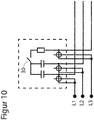
- FIG. 10 shows a cost-optimized electricity meter, which is designed to test its measuring devices automatically.
- the generation of different test states is dispensed with. Effective and reactive power measurement and the individual measuring units are not checked separately, but by a single test, which checks whether each of the modulated on the individual phases apparent power is measured correctly. For cost reasons, it is accepted that the test conditions for the individual phases are different and possibly sub-optimal. Since only one switch is required, a high-quality switch can be used, for example, a reed contact, which is designed for at least 10 million switching cycles and design-wise does not form this test negatively affecting aging phenomena.
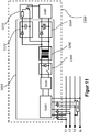
- FIG. 11 10 shows an electricity meter 1000 having a controller 1080, a modulatable load 1090, and a switching power supply 1010, which includes a three-phase rectifier 1020, a smoothing circuit 1030, a chopper 1040, a transformer 1050, a second smoothing circuit 1060, and a third smoothing circuit 1070.
- the switching power supply operates at a frequency well above the mains frequency, for example, 20 kHz.
- the chopper 1040 is driven rectangular with a frequency of 20 kHz.
- the smoothing circuit 1060 symbolically illustrates a diode and an electrolytic capacitor. It may also include other components, such as additional chokes and other electrolytic capacitors. The smoothing circuit 1060 feeds the controller 1080 and other components such as A / D converters, etc.
- the controller 1080 requires a well-defined voltage level, which is why the switching power supply 1010 has control means, not shown here, to regulate the voltage level to the desired value.
- the controller 1080 is thus represented here representative of the typical low voltage part of an electricity meter.
- the peculiarity in this figure represents the third smoothing circuit 1070, of which symbolically a diode and a capacitor are shown here. This capacitor is very small, serves to reduce a ripples and may possibly be omitted entirely.
- the smoothing circuit 1070 feeds the modulatable load 1090, which is symbolically represented here by resistor and transistor.
- the controller 1080 is configured to modulate the load 1090 according to the invention.
- the switching power supply 1010 has a common relationship between recorded and delivered power. As the power output increases, the power consumed increases.
- the modulated by the modulated load 1090 modulation of the output from the switching power supply 1010th Power causes a modulation of the power absorbed by the switching power supply 1010.
- capacitances built into the smoothing circuits 1030 and 1070 are dimensioned so small that the cutoff frequencies of the lowpasses formed by these capacitances are sufficiently high to allow the modulation to pass.
- the capacitor provided in the smoothing circuit 1060 can be dimensioned very large in order to ensure a reliable supply to the controller 1080 without this hindering the modulation.
- the controller 1080 is fed symmetrically from all three phases in a balanced network condition. This means that the modulation of the modulatable load 1090 reaches through to the ammeters of all three phases and leads to a modulation of the current measured values. If a parallel current path is established at a phase for the purpose of manipulation or power theft, as shown here by the example of L3 with the current path 950, then the measured current value determined by the associated current sensor is reduced. This reduces the difference between a first measured value of the instantaneous power, which is determined when the load 1090 is de-energized, and a second measured value of the instantaneous power, which is determined when the load 1090 is energized.
- the control 1080 obtains from its measured values for phase voltages and phase currents all the necessary information to calculate the instantaneous efficiency of the switched-mode power supply 1010 on the one hand and to determine the power components which are taken from the individual phases for the supply of the counter.
- the relationship between the voltage levels of the three phases and the power components is typically non-linear and can be stored, for example, in tables.
Claims (5)
- Procédé pour l'autotest de l'exactitude de mesure d'un compteur d'électricité (110), lequel est conçu pour la formation de données de facturation, dans lequel des valeurs de consommation et/ou des valeurs de puissance sont déterminées à partir de valeurs de mesure d'un instrument de mesure (910) du compteur d'électricité (110) et les valeurs de consommation et/ou les valeurs de puissance sont mises en relation avec une modulation prédéfinie, réalisée par un dispositif de contrôle (800), d'un consommateur de puissance modulable, afin de contrôler le fonctionnement de l'instrument de mesure (910).
- Dispositif comprenant un compteur d'électricité (110) conçu pour former des données de facturation, dans lequel le dispositif est adapté pour déterminer des valeurs de consommation et/ou des valeurs de puissance à partir de valeurs de mesure d'un instrument de mesure (910) du compteur d'électricité (110) et dans lequel le dispositif est adapté pour transmettre des signaux et/ou des données par le biais d'un réseau électrique existant (100) avec un consommateur de puissance modulable et pour reconstruire des signaux et/ou des données transmis/transmises par le consommateur de puissance modulable à partir des valeurs de consommation et/ou des valeurs de puissance, caractérisé en ce que le consommateur de puissance modulable présente un dispositif de contrôle (900) adapté pour réaliser une modulation prédéfinie du consommateur, où il est prévu un autotest de l'exactitude de mesure du compteur d'électricité (110), dans lequel les valeurs de consommation et/ou les valeurs de puissance sont mises en relation avec la modulation du consommateur de puissance modulable, afin de contrôler le fonctionnement de l'instrument de mesure (910).
- Dispositif selon la revendication 2, caractérisé en ce que le consommateur de puissance modulable est intégré dans le compteur d'électricité (110).
- Dispositif selon la revendication 3, caractérisé en ce que le compteur d'électricité (110) présente une partie de réseau de commutation (1010), au côté basse tension de laquelle est raccordé le consommateur de puissance modulable.
- Dispositif selon la revendication 4, caractérisé en ce que la partie de réseau de commutation (1010) présente un circuit de lissage de tension (1030) auquel est raccordé exclusivement le consommateur de puissance modulable.
Priority Applications (1)
| Application Number | Priority Date | Filing Date | Title |
|---|---|---|---|
| PL15201719T PL3035551T3 (pl) | 2014-12-19 | 2015-12-21 | Sposób i urządzenie do samotestowania dokładności pomiaru licznika energii elektrycznej |
Applications Claiming Priority (1)
| Application Number | Priority Date | Filing Date | Title |
|---|---|---|---|
| DE102014018809.4A DE102014018809A1 (de) | 2014-12-19 | 2014-12-19 | Übertragung über ein Stromnetz mit modulierbarem Verbraucher und Elektrizitätszähler |
Publications (2)
| Publication Number | Publication Date |
|---|---|
| EP3035551A1 EP3035551A1 (fr) | 2016-06-22 |
| EP3035551B1 true EP3035551B1 (fr) | 2019-08-14 |
Family
ID=55066365
Family Applications (1)
| Application Number | Title | Priority Date | Filing Date |
|---|---|---|---|
| EP15201719.0A Active EP3035551B1 (fr) | 2014-12-19 | 2015-12-21 | Procédé et dispositif pour l'autotest de l'exactitude de mesure d'un compteur d'electricite |
Country Status (3)
| Country | Link |
|---|---|
| EP (1) | EP3035551B1 (fr) |
| DE (1) | DE102014018809A1 (fr) |
| PL (1) | PL3035551T3 (fr) |
Cited By (2)
| Publication number | Priority date | Publication date | Assignee | Title |
|---|---|---|---|---|
| US20220116075A1 (en) * | 2020-10-08 | 2022-04-14 | Melexis Technologies Nv | Transmitter for power line communication |
| EP4246149A1 (fr) | 2022-03-18 | 2023-09-20 | EMH metering GmbH & Co. KG | Compteur d'électricité doté d'une commande électronique et d'une alimentation électrique |
Families Citing this family (4)
| Publication number | Priority date | Publication date | Assignee | Title |
|---|---|---|---|---|
| CN109444783A (zh) * | 2018-11-02 | 2019-03-08 | 国网湖南省电力有限公司 | 一种配电网一二次融合设备采样精度测试方法 |
| CN109901090B (zh) * | 2019-03-26 | 2020-08-04 | 国网北京市电力公司 | 变电站的测控设备 |
| CN111641536B (zh) * | 2020-05-27 | 2022-06-24 | 重庆邮电大学 | 一种物联网设备在线测试诊断方法 |
| CN111983304B (zh) * | 2020-07-01 | 2022-10-04 | 宁波三星医疗电气股份有限公司 | 一种电能表防窃电方法 |
Citations (1)
| Publication number | Priority date | Publication date | Assignee | Title |
|---|---|---|---|---|
| DE69824659T2 (de) * | 1997-04-08 | 2005-07-07 | Actaris Uk Limited, Felixstowe | Kalibrierungsverfahren für einen elektronischen Elektrizitätszähler |
Family Cites Families (11)
| Publication number | Priority date | Publication date | Assignee | Title |
|---|---|---|---|---|
| US4271390A (en) * | 1978-10-05 | 1981-06-02 | Canu John C | Electric watt-hour meter testing device |
| US5537029A (en) * | 1992-02-21 | 1996-07-16 | Abb Power T&D Company Inc. | Method and apparatus for electronic meter testing |
| US6177884B1 (en) | 1998-11-12 | 2001-01-23 | Hunt Technologies, Inc. | Integrated power line metering and communication method and apparatus |
| IT1320621B1 (it) * | 2000-09-05 | 2003-12-10 | Wrap Spa | Metodo, sistema ed apparati per la trasmissione di dati su reteelettrica |
| JP2002304687A (ja) | 2001-02-01 | 2002-10-18 | Akiyoshi Mori | インホームサーヴェイランスシステム |
| NZ530254A (en) | 2003-12-16 | 2006-10-27 | Pulse Utilities Ltd | A power line communication system and an intelligent meter therefor |
| EP1794895B8 (fr) | 2004-09-29 | 2019-02-27 | Beck, Wilfried | Procede et systeme de transmission de donnees pour reseaux a tension alternative |
| CH704747B1 (de) | 2006-04-21 | 2012-10-15 | Fachhochschule Konstanz | Zählwaage mit Multilevel-Hinkley-Detektor. |
| DE102008044909A1 (de) * | 2008-08-31 | 2010-03-04 | Lübeck, Felix | Verfahren zur Erkennung von Notfällen mittels fernausgelesener Zähler |
| GB2469361B (en) * | 2010-01-28 | 2011-04-13 | Energy2Trade Ltd | Power flow measurement and management |
| US8619846B2 (en) * | 2011-04-21 | 2013-12-31 | Landis+Gyr | Amplitude control in a variable load environment |
-
2014
- 2014-12-19 DE DE102014018809.4A patent/DE102014018809A1/de not_active Withdrawn
-
2015
- 2015-12-21 EP EP15201719.0A patent/EP3035551B1/fr active Active
- 2015-12-21 PL PL15201719T patent/PL3035551T3/pl unknown
Patent Citations (1)
| Publication number | Priority date | Publication date | Assignee | Title |
|---|---|---|---|---|
| DE69824659T2 (de) * | 1997-04-08 | 2005-07-07 | Actaris Uk Limited, Felixstowe | Kalibrierungsverfahren für einen elektronischen Elektrizitätszähler |
Cited By (2)
| Publication number | Priority date | Publication date | Assignee | Title |
|---|---|---|---|---|
| US20220116075A1 (en) * | 2020-10-08 | 2022-04-14 | Melexis Technologies Nv | Transmitter for power line communication |
| EP4246149A1 (fr) | 2022-03-18 | 2023-09-20 | EMH metering GmbH & Co. KG | Compteur d'électricité doté d'une commande électronique et d'une alimentation électrique |
Also Published As
| Publication number | Publication date |
|---|---|
| PL3035551T3 (pl) | 2020-03-31 |
| EP3035551A1 (fr) | 2016-06-22 |
| DE102014018809A1 (de) | 2016-06-23 |
Similar Documents
| Publication | Publication Date | Title |
|---|---|---|
| EP3035551B1 (fr) | Procédé et dispositif pour l'autotest de l'exactitude de mesure d'un compteur d'electricite | |
| DE112010001638B4 (de) | Vorrichtung und Verfahren für Stromverbrauchsmessungen an Trennschalterpunkten | |
| DE112012002325T5 (de) | Verteiltes Elektrizitätszählersystem | |
| EP2369353B1 (fr) | Dispositif de mesure de courant sans contact et système de mesure d'énergie de consommateurs | |
| DE112007000244T5 (de) | Drahtloses System für ein oder mehrere elektrische Schaltvorrichtungen | |
| DE4300736C2 (de) | Kombinierte Erdschlußunterbrechungsschaltung mit Fernsteuerschalteinrichtung | |
| DE112011102285T5 (de) | System und Verfahren zum Regulieren der RMS-Spannung, an die eine Last angelegt ist | |
| EP2087318A1 (fr) | Dispositif pour la détermination et/ou la surveillance d'au moins une grandeur de processus | |
| EP2483990B1 (fr) | Appareil pour modifier une tension alternative, tension alternative avec signal de données superposé, méthode pour la transmission de données, utilisation d'un récepteur et architecture de communication | |
| DE202010000364U1 (de) | Kontaktlose Strommessvorrichtung und Verbraucherenergiemesssystem | |
| DE102012109468B3 (de) | Stromzählereinrichtung | |
| DE102011054748B4 (de) | Steuergerät für busgesteuerte Betriebsgeräte | |
| WO2017125605A1 (fr) | Procédé et dispositif de détection de consommateurs présents dans un réseau d'alimentation | |
| EP4152561A1 (fr) | Agencement et méthode d'affectation des phases | |
| DE102018106940A1 (de) | Messvorrichtung, Messsystem und Verfahren zur verteilten Energiemessung | |
| DE102016113028A1 (de) | System zur überwachung des energieverbrauchs in industrieanlagen und energiemess – und übertragungsmodul hierfür | |
| EP1910853A2 (fr) | Procede et circuit permettant de determiner la presence d'une fausse connexion d'un appareil electrique, en particulier d'un appareil electromenager, a une source de tension alternative de secteur | |
| DE10214738B4 (de) | Falschanschlusserkennungsschaltung und Verfahren zur Erkennung eines Falschanschlusses | |
| DE10103541A1 (de) | System zum Überwachen von Flughafenlampen | |
| DE112014002160B4 (de) | Modul mit passiver Messsignalrückführung über Ladungsspeicher | |
| WO2011160815A1 (fr) | Dispositif et procédé pour mesurer un travail électrique | |
| DE202024100016U1 (de) | Vorrichtung, welche eine Unterstützung für die Nachrüstung eines intelligenten Zählers bereitstellt | |
| EP3261260B1 (fr) | Appareil ménager électrique comprenant un dispositif de transmission de données et dispositif de réception de données provenant d'un tel dispositif | |
| WO2016131887A1 (fr) | Détection d'une discontinuité électrique générée par un changeur de prises, sur la base d'une caractéristique de qualité de réseau | |
| DE102021131297A1 (de) | Verfahren zum betreiben einer ladestation, ladestation und system mit einer mehrzahl von ladestationen |
Legal Events
| Date | Code | Title | Description |
|---|---|---|---|
| PUAI | Public reference made under article 153(3) epc to a published international application that has entered the european phase |
Free format text: ORIGINAL CODE: 0009012 |
|
| AK | Designated contracting states |
Kind code of ref document: A1 Designated state(s): AL AT BE BG CH CY CZ DE DK EE ES FI FR GB GR HR HU IE IS IT LI LT LU LV MC MK MT NL NO PL PT RO RS SE SI SK SM TR |
|
| AX | Request for extension of the european patent |
Extension state: BA ME |
|
| STAA | Information on the status of an ep patent application or granted ep patent |
Free format text: STATUS: REQUEST FOR EXAMINATION WAS MADE |
|
| 17P | Request for examination filed |
Effective date: 20161219 |
|
| RBV | Designated contracting states (corrected) |
Designated state(s): AL AT BE BG CH CY CZ DE DK EE ES FI FR GB GR HR HU IE IS IT LI LT LU LV MC MK MT NL NO PL PT RO RS SE SI SK SM TR |
|
| STAA | Information on the status of an ep patent application or granted ep patent |
Free format text: STATUS: EXAMINATION IS IN PROGRESS |
|
| 17Q | First examination report despatched |
Effective date: 20170801 |
|
| GRAP | Despatch of communication of intention to grant a patent |
Free format text: ORIGINAL CODE: EPIDOSNIGR1 |
|
| STAA | Information on the status of an ep patent application or granted ep patent |
Free format text: STATUS: GRANT OF PATENT IS INTENDED |
|
| INTG | Intention to grant announced |
Effective date: 20190311 |
|
| GRAS | Grant fee paid |
Free format text: ORIGINAL CODE: EPIDOSNIGR3 |
|
| GRAA | (expected) grant |
Free format text: ORIGINAL CODE: 0009210 |
|
| STAA | Information on the status of an ep patent application or granted ep patent |
Free format text: STATUS: THE PATENT HAS BEEN GRANTED |
|
| AK | Designated contracting states |
Kind code of ref document: B1 Designated state(s): AL AT BE BG CH CY CZ DE DK EE ES FI FR GB GR HR HU IE IS IT LI LT LU LV MC MK MT NL NO PL PT RO RS SE SI SK SM TR |
|
| REG | Reference to a national code |
Ref country code: GB Ref legal event code: FG4D Free format text: NOT ENGLISH |
|
| REG | Reference to a national code |
Ref country code: CH Ref legal event code: EP Ref country code: AT Ref legal event code: REF Ref document number: 1168235 Country of ref document: AT Kind code of ref document: T Effective date: 20190815 |
|
| REG | Reference to a national code |
Ref country code: IE Ref legal event code: FG4D Free format text: LANGUAGE OF EP DOCUMENT: GERMAN |
|
| REG | Reference to a national code |
Ref country code: DE Ref legal event code: R096 Ref document number: 502015009968 Country of ref document: DE |
|
| REG | Reference to a national code |
Ref country code: CH Ref legal event code: NV Representative=s name: ISLER AND PEDRAZZINI AG, CH |
|
| REG | Reference to a national code |
Ref country code: NL Ref legal event code: MP Effective date: 20190814 |
|
| REG | Reference to a national code |
Ref country code: LT Ref legal event code: MG4D |
|
| PG25 | Lapsed in a contracting state [announced via postgrant information from national office to epo] |
Ref country code: PT Free format text: LAPSE BECAUSE OF FAILURE TO SUBMIT A TRANSLATION OF THE DESCRIPTION OR TO PAY THE FEE WITHIN THE PRESCRIBED TIME-LIMIT Effective date: 20191216 Ref country code: NO Free format text: LAPSE BECAUSE OF FAILURE TO SUBMIT A TRANSLATION OF THE DESCRIPTION OR TO PAY THE FEE WITHIN THE PRESCRIBED TIME-LIMIT Effective date: 20191114 Ref country code: SE Free format text: LAPSE BECAUSE OF FAILURE TO SUBMIT A TRANSLATION OF THE DESCRIPTION OR TO PAY THE FEE WITHIN THE PRESCRIBED TIME-LIMIT Effective date: 20190814 Ref country code: FI Free format text: LAPSE BECAUSE OF FAILURE TO SUBMIT A TRANSLATION OF THE DESCRIPTION OR TO PAY THE FEE WITHIN THE PRESCRIBED TIME-LIMIT Effective date: 20190814 Ref country code: LT Free format text: LAPSE BECAUSE OF FAILURE TO SUBMIT A TRANSLATION OF THE DESCRIPTION OR TO PAY THE FEE WITHIN THE PRESCRIBED TIME-LIMIT Effective date: 20190814 Ref country code: HR Free format text: LAPSE BECAUSE OF FAILURE TO SUBMIT A TRANSLATION OF THE DESCRIPTION OR TO PAY THE FEE WITHIN THE PRESCRIBED TIME-LIMIT Effective date: 20190814 Ref country code: BG Free format text: LAPSE BECAUSE OF FAILURE TO SUBMIT A TRANSLATION OF THE DESCRIPTION OR TO PAY THE FEE WITHIN THE PRESCRIBED TIME-LIMIT Effective date: 20191114 Ref country code: NL Free format text: LAPSE BECAUSE OF FAILURE TO SUBMIT A TRANSLATION OF THE DESCRIPTION OR TO PAY THE FEE WITHIN THE PRESCRIBED TIME-LIMIT Effective date: 20190814 |
|
| PG25 | Lapsed in a contracting state [announced via postgrant information from national office to epo] |
Ref country code: ES Free format text: LAPSE BECAUSE OF FAILURE TO SUBMIT A TRANSLATION OF THE DESCRIPTION OR TO PAY THE FEE WITHIN THE PRESCRIBED TIME-LIMIT Effective date: 20190814 Ref country code: AL Free format text: LAPSE BECAUSE OF FAILURE TO SUBMIT A TRANSLATION OF THE DESCRIPTION OR TO PAY THE FEE WITHIN THE PRESCRIBED TIME-LIMIT Effective date: 20190814 Ref country code: LV Free format text: LAPSE BECAUSE OF FAILURE TO SUBMIT A TRANSLATION OF THE DESCRIPTION OR TO PAY THE FEE WITHIN THE PRESCRIBED TIME-LIMIT Effective date: 20190814 Ref country code: IS Free format text: LAPSE BECAUSE OF FAILURE TO SUBMIT A TRANSLATION OF THE DESCRIPTION OR TO PAY THE FEE WITHIN THE PRESCRIBED TIME-LIMIT Effective date: 20191214 Ref country code: RS Free format text: LAPSE BECAUSE OF FAILURE TO SUBMIT A TRANSLATION OF THE DESCRIPTION OR TO PAY THE FEE WITHIN THE PRESCRIBED TIME-LIMIT Effective date: 20190814 Ref country code: GR Free format text: LAPSE BECAUSE OF FAILURE TO SUBMIT A TRANSLATION OF THE DESCRIPTION OR TO PAY THE FEE WITHIN THE PRESCRIBED TIME-LIMIT Effective date: 20191115 |
|
| PG25 | Lapsed in a contracting state [announced via postgrant information from national office to epo] |
Ref country code: TR Free format text: LAPSE BECAUSE OF FAILURE TO SUBMIT A TRANSLATION OF THE DESCRIPTION OR TO PAY THE FEE WITHIN THE PRESCRIBED TIME-LIMIT Effective date: 20190814 |
|
| PG25 | Lapsed in a contracting state [announced via postgrant information from national office to epo] |
Ref country code: RO Free format text: LAPSE BECAUSE OF FAILURE TO SUBMIT A TRANSLATION OF THE DESCRIPTION OR TO PAY THE FEE WITHIN THE PRESCRIBED TIME-LIMIT Effective date: 20190814 Ref country code: DK Free format text: LAPSE BECAUSE OF FAILURE TO SUBMIT A TRANSLATION OF THE DESCRIPTION OR TO PAY THE FEE WITHIN THE PRESCRIBED TIME-LIMIT Effective date: 20190814 Ref country code: EE Free format text: LAPSE BECAUSE OF FAILURE TO SUBMIT A TRANSLATION OF THE DESCRIPTION OR TO PAY THE FEE WITHIN THE PRESCRIBED TIME-LIMIT Effective date: 20190814 |
|
| PG25 | Lapsed in a contracting state [announced via postgrant information from national office to epo] |
Ref country code: CZ Free format text: LAPSE BECAUSE OF FAILURE TO SUBMIT A TRANSLATION OF THE DESCRIPTION OR TO PAY THE FEE WITHIN THE PRESCRIBED TIME-LIMIT Effective date: 20190814 Ref country code: SM Free format text: LAPSE BECAUSE OF FAILURE TO SUBMIT A TRANSLATION OF THE DESCRIPTION OR TO PAY THE FEE WITHIN THE PRESCRIBED TIME-LIMIT Effective date: 20190814 Ref country code: IS Free format text: LAPSE BECAUSE OF FAILURE TO SUBMIT A TRANSLATION OF THE DESCRIPTION OR TO PAY THE FEE WITHIN THE PRESCRIBED TIME-LIMIT Effective date: 20200224 Ref country code: SK Free format text: LAPSE BECAUSE OF FAILURE TO SUBMIT A TRANSLATION OF THE DESCRIPTION OR TO PAY THE FEE WITHIN THE PRESCRIBED TIME-LIMIT Effective date: 20190814 |
|
| REG | Reference to a national code |
Ref country code: DE Ref legal event code: R097 Ref document number: 502015009968 Country of ref document: DE |
|
| PLBE | No opposition filed within time limit |
Free format text: ORIGINAL CODE: 0009261 |
|
| STAA | Information on the status of an ep patent application or granted ep patent |
Free format text: STATUS: NO OPPOSITION FILED WITHIN TIME LIMIT |
|
| PG2D | Information on lapse in contracting state deleted |
Ref country code: IS |
|
| 26N | No opposition filed |
Effective date: 20200603 |
|
| REG | Reference to a national code |
Ref country code: BE Ref legal event code: MM Effective date: 20191231 |
|
| PG25 | Lapsed in a contracting state [announced via postgrant information from national office to epo] |
Ref country code: MC Free format text: LAPSE BECAUSE OF FAILURE TO SUBMIT A TRANSLATION OF THE DESCRIPTION OR TO PAY THE FEE WITHIN THE PRESCRIBED TIME-LIMIT Effective date: 20190814 Ref country code: SI Free format text: LAPSE BECAUSE OF FAILURE TO SUBMIT A TRANSLATION OF THE DESCRIPTION OR TO PAY THE FEE WITHIN THE PRESCRIBED TIME-LIMIT Effective date: 20190814 |
|
| GBPC | Gb: european patent ceased through non-payment of renewal fee |
Effective date: 20191221 |
|
| PG25 | Lapsed in a contracting state [announced via postgrant information from national office to epo] |
Ref country code: LU Free format text: LAPSE BECAUSE OF NON-PAYMENT OF DUE FEES Effective date: 20191221 Ref country code: IE Free format text: LAPSE BECAUSE OF NON-PAYMENT OF DUE FEES Effective date: 20191221 Ref country code: GB Free format text: LAPSE BECAUSE OF NON-PAYMENT OF DUE FEES Effective date: 20191221 |
|
| PG25 | Lapsed in a contracting state [announced via postgrant information from national office to epo] |
Ref country code: BE Free format text: LAPSE BECAUSE OF NON-PAYMENT OF DUE FEES Effective date: 20191231 |
|
| PG25 | Lapsed in a contracting state [announced via postgrant information from national office to epo] |
Ref country code: CY Free format text: LAPSE BECAUSE OF FAILURE TO SUBMIT A TRANSLATION OF THE DESCRIPTION OR TO PAY THE FEE WITHIN THE PRESCRIBED TIME-LIMIT Effective date: 20190814 |
|
| PG25 | Lapsed in a contracting state [announced via postgrant information from national office to epo] |
Ref country code: HU Free format text: LAPSE BECAUSE OF FAILURE TO SUBMIT A TRANSLATION OF THE DESCRIPTION OR TO PAY THE FEE WITHIN THE PRESCRIBED TIME-LIMIT; INVALID AB INITIO Effective date: 20151221 Ref country code: MT Free format text: LAPSE BECAUSE OF FAILURE TO SUBMIT A TRANSLATION OF THE DESCRIPTION OR TO PAY THE FEE WITHIN THE PRESCRIBED TIME-LIMIT Effective date: 20190814 |
|
| REG | Reference to a national code |
Ref country code: AT Ref legal event code: MM01 Ref document number: 1168235 Country of ref document: AT Kind code of ref document: T Effective date: 20201221 |
|
| PG25 | Lapsed in a contracting state [announced via postgrant information from national office to epo] |
Ref country code: AT Free format text: LAPSE BECAUSE OF NON-PAYMENT OF DUE FEES Effective date: 20201221 |
|
| PG25 | Lapsed in a contracting state [announced via postgrant information from national office to epo] |
Ref country code: MK Free format text: LAPSE BECAUSE OF FAILURE TO SUBMIT A TRANSLATION OF THE DESCRIPTION OR TO PAY THE FEE WITHIN THE PRESCRIBED TIME-LIMIT Effective date: 20190814 |
|
| PGFP | Annual fee paid to national office [announced via postgrant information from national office to epo] |
Ref country code: CH Payment date: 20230103 Year of fee payment: 8 |
|
| PGFP | Annual fee paid to national office [announced via postgrant information from national office to epo] |
Ref country code: IT Payment date: 20221230 Year of fee payment: 8 Ref country code: DE Payment date: 20230209 Year of fee payment: 8 |
|
| PGFP | Annual fee paid to national office [announced via postgrant information from national office to epo] |
Ref country code: FR Payment date: 20231220 Year of fee payment: 9 |
|
| PGFP | Annual fee paid to national office [announced via postgrant information from national office to epo] |
Ref country code: PL Payment date: 20231122 Year of fee payment: 9 |
|
| PGFP | Annual fee paid to national office [announced via postgrant information from national office to epo] |
Ref country code: DE Payment date: 20240208 Year of fee payment: 9 Ref country code: CH Payment date: 20240110 Year of fee payment: 9 |