EP3034918B1 - Füllventil - Google Patents
Füllventil Download PDFInfo
- Publication number
- EP3034918B1 EP3034918B1 EP14198187.8A EP14198187A EP3034918B1 EP 3034918 B1 EP3034918 B1 EP 3034918B1 EP 14198187 A EP14198187 A EP 14198187A EP 3034918 B1 EP3034918 B1 EP 3034918B1
- Authority
- EP
- European Patent Office
- Prior art keywords
- seat
- wall
- axis
- fill valve
- valve according
- Prior art date
- Legal status (The legal status is an assumption and is not a legal conclusion. Google has not performed a legal analysis and makes no representation as to the accuracy of the status listed.)
- Active
Links
Images

Classifications
-
- F—MECHANICAL ENGINEERING; LIGHTING; HEATING; WEAPONS; BLASTING
- F16—ENGINEERING ELEMENTS AND UNITS; GENERAL MEASURES FOR PRODUCING AND MAINTAINING EFFECTIVE FUNCTIONING OF MACHINES OR INSTALLATIONS; THERMAL INSULATION IN GENERAL
- F16K—VALVES; TAPS; COCKS; ACTUATING-FLOATS; DEVICES FOR VENTING OR AERATING
- F16K27/00—Construction of housing; Use of materials therefor
- F16K27/02—Construction of housing; Use of materials therefor of lift valves
Definitions
- the invention relates to a filling valve specified in the preamble of claim 1. Art.
- EP 10 39 185 B1 becomes one from the DE 299 05 322 U1 known filling valve as prior art ( Fig. 5 ), in which the inner and outer walls of each kidney-shaped passage are parallel to one another and enclose an inclination angle of about 40 ° with the axis of the seat housing.
- improved filling valve include the inner and outer walls with the axis an even greater angle of inclination. From the relatively large angle of inclination of the inner and outer walls of the kidney-shaped passages results in given useful diameter of the filling valve, the need to form the upper mouths of the passages axially parallel, which requires additional processing steps.
- the transition from the outer wall to the seat is step-like.
- the invention has for its object to improve a filling valve of the type mentioned so that a given increase in the size of the filling valve, a significant increase in the maximum volume flow without risk of Kavitationsrial is possible.
- the outer wall can be increased when creating the filling valve made of steel for a given size of the filling valve, the maximum flow without cavitation by about 20% and the pressure loss in the flow reduced by about 30%, wherein the angle of inclination of the outer wall may be combined with other fluidic optimizations.
- the small angle of inclination of the outer wall has initially indicated in computer simulations executed for both flow directions with speed and pressure contour plots as a surprising solution to the problem. The required increase is to the extent expected in test arrangements in which hydraulic media are processed, as used in presses and injection molding machines.
- the increase in the maximum volume flow allows an increase in the speed of the press piston with the same size of the filling valve used.
- the steepness of the outer wall is that the passage in one operation from one or the other side of the seat housing, for example, by milling, can be formed and does not have to be converted between several processing steps.
- the angle of inclination in the passage allows a longer guide for the shaft of the poppet valve.
- the inner wall and the outer wall may include the same inclination angle with the axis.
- the passageway thus remains substantially constant, but reduces the useful cross-section towards the seat, because the lower mouth of the passage is on a smaller diameter than the upper mouth.
- the inner wall may include an inclination angle between 40 ° and 25 ° at least adjacent to the seat with the axis, so that the passage width in the direction to the seat increases. In this case, the inclination angle of the inner wall with respect to the axis is smaller, the smaller the inclination angle of the outer wall.
- two webs are provided in the seat housing, preferably with web thickness decreasing in the direction towards the seat, and between these two kidney-shaped, preferably milled through passages, which are preferably concentric with the axis of the filling valve.
- a maximum increase in the volume flow can be achieved.
- bores of a bore collar could define the passageways.
- kidney-shaped passageways could define the passageways.
- the flow conditions are further improved by the outer wall with a convex curve leads to an approximately axis-parallel transition to the seat.
- This transition is, preferably, so long that it is about 10% of the seat diameter, so that it guides adhering flow cleanly towards the edge of the lifted plate.
- Another favorable measure is to let the inner wall to end at an annular bead, which - seen in an axial section - is convexly rounded from the inner wall into a receiving bore of the shaft of the poppet valve. This measure improves the flow, for example, from the passage to the shaft and to the top of the plate.
- the filling valve there is a specific size of the filling valve.
- seals are arranged sunk, on the one hand perform the seal to the press cylinder and on the other hand sealing to a tank, and define at least on the side of the press cylinder an inner useful diameter of the filling valve, which is chosen as large as possible.
- a large maximum flow rate is achieved in particular when the seat diameter is about 75% to 85% of the useful diameter, i. the seat and correspondingly also the outer diameter of the poppet valve are increased compared to known solutions of the same size, for example by 8% to 10%.
- Another measure to improve the flow conditions is to provide a concave, approximately a quarter circle corresponding rounding between the seat and the plate side of the seat housing a countersink in the plate side. This results in a better flow pattern compared to a conical shape.
- a peripheral undercut is provided in the recess, and, preferably, set the top wall at a distance from the seat, which corresponds to a maximum of 10% of the useful diameter, preferably about 5% to 8% of the useful diameter. From this depression and in particular the undercut result very clean transitions from the kidney-shaped passages into the seating area and the bead.
- the bead may have an outer diameter in the top wall of the recess which corresponds to about 40% of the seat diameter.
- a filling valve F according to Fig. 1 is particularly intended for use in hydraulic presses or hydraulically operated injection molding machines, for example, to quickly fill and empty a press cylinder containing a press piston can.
- the filling valve can be hydraulically controlled and open automatically in a Nachsaugsituation.
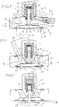
- the filling valve F has a disk-shaped seat housing 1 made of steel, on which on one side 5 on webs 3 a control 2 is mounted. Between the webs 3 kidney-shaped passages 4 are formed by machining. On the outer circumference of the seat housing 1 a cylinder screw 8 can be mounted, which contains a hydraulic access to the control 2. Further, a Verschleussschraube 7 may be mounted on the outside. The side 5 facing away from the seat housing 1 is denoted by 6.
- the two webs 3 define two kidney-shaped passages 4, which are concentric to the axis 40 of the seat housing and each have an outer wall 13 and an inner wall 31, which are connected via the webs 3 bounding, approximately semicircular transitions 38, such in that an orifice 11 facing the side 5 and an orifice 12 in the region of a seat 24 formed inside the seat housing 1 are present.
- the passages 4 comprising a circular groove 9 for receiving a ring seal 23 (FIG. Fig. 3 ) incorporated in the seat housing 1.
- Fig. 3 It can be seen that the seat 24 designed as a circular edge, possibly with a chamfer, is assigned a poppet valve 15 which has a plate 16 and a central shaft 17 which projects upwards into the control unit 2 and by a weak follow-up spring 20 is acted upon in the direction of the shut-off position shown on the seat 24.
- a Aufberichtkolben 14 is included in the control 2, which is hydraulically acted upon by a strong Aufmaschinefeder 21 via a line 22 to hydraulicallyteil horrn the filling valve F.
- the plate 16 has an approximately flat or slightly domed top 18 and a significantly centered cambered bottom 19, wherein the shaft 17 a concave rounded transition to the top 18 leads.
- annular seal 23 is included, which defines an inner useful diameter N of the filling valve F, for example, according to the inner diameter of a dot-dash line indicated pressing cylinder Z, or in which the filling valve F is to be mounted.
- N an inner useful diameter of the filling valve F
- a concave shaped transition 25 corresponding to the seat 24 is formed approximately at a quarter circle.
- This extending in the circumferential direction transition 25 belongs to a centric, z. B. by turning, formed recess 26 in the side 6, which has a substantially flat and perpendicular to the axis 40 top wall 27 outside the two orifices 12, which comprises an annular bead 28 about a receiving bore 29 for the shaft 17.
- the annular bead 28 is rounded starting from the top wall 27 into the receiving bore 29 concave.
- a slight undercut 30 is rotated.
- the seen in the direction of the axis 40 distance X of the top wall 27 from the seat 24 is about 5% - 8% of the effective diameter N, possibly even up to 10%.
- the passages 4 are blended with the seat 24 and the recess.
- Fig. 4 illustrates the geometric design, especially of the two passages 4 to the seat 24 and the bead 28.
- the outer wall 13 of each passage 4 has a substantially rectilinear generatrix and is according to the invention with an inclination angle ⁇ between 25 ° and 20 ° relative to the axis 40th inclined inwards towards the seat 24.
- the inner wall 31 may have the same inclination angle ⁇ as the outer wall 13.
- the inner wall 31 has a greater inclination angle ⁇ between 40 ° and 25 ° with respect to the axis 40, the smaller the inclination angle ⁇ is the inclination angle ⁇ of the inner wall. Due to the different angles of inclination ⁇ and ⁇ , the passage width widens towards the seat 24. However, the inner and outer walls must be machined separately, e.g. be milled.
- the outer wall 13 leads via a convex curve 39 and an approximately axis-parallel transition 32 to the seat 24, wherein the transition 32 has a height y, which is preferably about 10% of the seat diameter d.
- the height of the seat housing 1 is for example about 60% of the seat diameter d.
- each passage 4 is formed by mutually parallel inner and outer walls 13, 31 by milling, the machining in a work train from either side 5 or side 6 is possible. If the angle of inclination ⁇ of the inner wall 31 is different from the angle of inclination ⁇ of the outer wall 31, at least in a region adjacent to the height position of the seat 24 or in the lower part to the bead 28, then a second step for free milling of the inclination angle ⁇ is required, but in turn can be performed in a move from example page 6 from.
- kidney-shaped passages 4 instead of the two kidney-shaped passages 4, a drill collar, e.g. be provided with eight or nine equal holes. However, the kidney-shaped passages 4 are given preference.
- Fig. 5 shows the filling valve F in an intake situation against the suction spring 20 lifted from the seat 24 poppet valve 15.
- the filling valve F is then from top to bottom, that is, from T to Z, flows through.
- the poppet valve 15 are brought into the same maximum stroke position by acting on the control piston 14 against the Aufberichtfeder 21.
Landscapes
- Engineering & Computer Science (AREA)
- General Engineering & Computer Science (AREA)
- Mechanical Engineering (AREA)
- Details Of Valves (AREA)
- Lift Valve (AREA)
Description
- Die Erfindung betrifft ein Füllventil der im Oberbegriff des Patentanspruchs 1 angegebenen Art.
- In
EP 10 39 185 B1 wird ein aus derDE 299 05 322 U1 bekanntes Füllventil als Stand der Technik (Fig. 5 ) gezeigt und beschrieben, bei dem die Innen- und Außenwände jedes nierenförmigen Durchgangs zueinander parallel sind und mit der Achse des Sitzgehäuses einen Neigungswinkel von etwa 40° einschließen. Bei dem inEP 10 39 185 B1 gegenüber dem vorerwähnten Füllventil verbesserten Füllventil schließen die Innen- und Außenwände mit der Achse einen sogar noch größeren Neigungswinkel ein. Aus dem relativ großen Neigungswinkel der Innen- und Außenwände der nierenförmigen Durchgänge resultiert bei gegebenem Nutzdurchmesser des Füllventils die Notwendigkeit, die oberen Mündungen der Durchgänge achsparallel zu formen, was zusätzliche Bearbeitungsschritte erfordert. Der Übergang von der Außenwand zum Sitz ist stufenartig. An der der Aufsteuerung abgewandten Seite des Sitzgehäuses ist eine konische Ansenkung bis zum Sitz geformt, die einen etwas kleineren Kegelwinkel hat als die kegelige Oberseite des Tellers des Tellerventils. Aus diesen geometrischen Verhältnissen resultiert bei der Auslegung des Füllventils entsprechendem, maximalem Volumenstrom und voll geöffnetem Tellerventil in jeder Durchströmrichtung, speziell im Bereich starker Umlenkung über den Sitz und um den Rand des Tellers ein unerwünscht hoher Druckverlust. Dieser Druckverlust begrenzt den maximalen Volumenstrom und somit die Geschwindigkeit des Pressenkolbens, der unter Nutzen des Füllventils seinen Leerhub bis zum eigentlichen Presszyklus bzw. seinen Rückhub nach Ausführen des Presszyklus so schnell wie möglich ausführen können sollte, um die Zykluszeit zu optimieren. Bei dem in dem bekannten Füllventil resultiert z.B. eine Überhöhung des maximalen Volumenstroms beispielsweise um 20 % unvermeidbar in Kavitationserscheinungen als Folge des zu starken Unterdrucks. Der starke Druckverlust ergibt sich aus einer sehr starken Erhöhung der Strömungsgeschwindigkeit speziell um den Rand des Tellers des Tellerventils, bedingt durch die relativ starke Umlenkung in der Strömung durch das Ventilgehäuse zur andern Seite, und auch durch lokale Querschnittsverengungen. Die Strömung ist nicht im gesamten zur Verfügung stehenden Strömungsquerschnitt gleichmäßig schnell, sondern es sind relativ viele Totzonen im Strömungsbild enthalten. - Bei dem aus
JP S 57 156 896 A Fig. 2 und3 gezeigten Durchgänge mit ihren Außen- und Innenwänden mit der Achse des Sitzes einen Neigungswinkel von 33° bis 35° ein. Aus diesem relativ großen Neigungswinkel resultiert im Bereich des Sitzes eine starke Umlenkung sowie ein unerwünscht hoher Druckverlust um den Rand des Tellers. - Bei dem aus
US 2152870 A bekannten Füllventile schließen die Wände der Durchgänge mit der Achse des Sitzes sogar noch größere Neigungswinkel von mehr als 60° ein, woraus unerwünscht große Druckverluste resultieren. - Die Forderung von Anwendern des Füllventils, höhere Pressenzylindergeschwindigkeiten fahren zu können als bisher, lässt sich mit den bekannten Konzepten nicht erfüllen, da der maximal mögliche Volumenstrom in jeder Baugröße des Füllventils unzweckmäßig begrenzt ist.
- Der Erfindung liegt die Aufgabe zugrunde, ein Füllventil der eingangs genannten Art so zu verbessern, dass bei gegebener Baugröße des Füllventils eine erhebliche Steigerung des maximalen Volumenstroms ohne Gefahr einer Kavitationswirkung möglich ist.
- Die gestellte Aufgabe wird mit den Merkmalen des Patentanspruchs 1 gelöst.
- Aus dem relativ kleinen, mit der Achse eingeschlossenen Neigungswinkel von nur 20° bis 25° zumindest der Außenwand lässt sich bei Erstellung des Füllventils aus Stahl für eine gegebene Baugröße des Füllventils der maximale Volumenstrom ohne Kavitationsgefahr um ca. 20 % steigern und wird der Druckverlust in der Strömung um über etwa 30 % reduziert, wobei der Neigungswinkel der Außenwand kombiniert sein kann mit weiteren strömungstechnischen Optimierungen. Der kleine Neigungswinkel der Außenwand hat sich zunächst in ausgeführten Computersimulationen für beide Strömungsrichtungen mit Geschwindigkeits- und Druck-Kontur-Plots als überraschende Lösung des Problems angedeutet. Die geforderte Steigerung zeigt sich im erwarteten Ausmaß in Prüfanordnungen, in denen Hydraulikmedien verarbeitet werden, wie sie in Pressen und Spritzgussmaschinen zum Einsatz kommen. Die Steigerung des maximalen Volumenstroms ermöglicht eine Erhöhung der Geschwindigkeit des Pressenkolbens bei gleicher Baugröße des eingesetzten Füllventils. Ein weiterer Vorteil der Steilheit der Außenwand liegt darin, dass der Durchgang in einem Arbeitsgang von einer oder von der anderen Seite des Sitzgehäuses spanend, z.B. durch Fräsen, gebildet werden kann und nicht zwischen mehreren Bearbeitungsschritten umgerüstet werden muss. Auch ermöglicht der Neigungswinkel im Durchgang eine längere Führung für den Schaft des Tellerventils. Die Innenwand und die Außenwand können den gleichen Neigungswinkel mit der Achse einschließen. Die Durchgangsweite bleibt somit im Wesentlichen konstant, wobei sich jedoch der nutzbare Querschnitt in Richtung zum Sitz verringert, weil die untere Mündung des Durchgangs auf einem kleineren Durchmesser liegt als die obere Mündung. Um diesen geometrisch bedingten Umstand zumindest teilweise zu kompensieren, kann die Innenwand zumindest angrenzend an den Sitz mit der Achse einen Neigungswinkel zwischen 40° und 25°einschließen, so dass die Durchgangsweite in Richtung zum Sitz zunimmt. Dabei ist der Neigungswinkel der Innenwand bezogen auf die Achse umso kleiner, desto kleiner der Neigungswinkel der Außenwand ist.
- Bei einer zweckmäßigen Ausführungsform sind im Sitzgehäuse zwei Stege, vorzugsweise mit in Richtung zum Sitz abnehmender Stegstärke, und zwischen diesen zwei nierenförmige, vorzugsweise zur Achse des Füllventils konzentrische, gefräste Durchgänge vorgesehen. In dieser Ausbildung lässt sich eine maximale Steigerung des Volumenstroms erzielen. Alternativ könnten anstelle nierenförmiger Durchgänge auch Bohrungen eines Bohrungskranzes die Durchgänge definieren. Jedoch ergeben sich bei einem Bohrungskranz ein gegenüber nierenförmigen Durchgängen verringerter Gesamtströmungsquerschnitt und eine Zunahme des Druckverlustes, so dass Ausführungen mit nierenförmigen Durchgängen der Vorzug zu geben ist.
- Bei einer weiteren Ausführungsform werden die Strömungsverhältnisse weiter verbessert, indem die Außenwand mit einer konvexen Rundung zu einem annähernd achsparallelen Übergang zum Sitz führt. Dieser Übergang ist, vorzugsweise, so lang, dass er etwa 10 % des Sitzdurchmessers beträgt, damit er anhaftende Strömung sauber in Richtung zur Kante des abgehobenen Tellers lenkt. Eine andere günstige Maßnahme besteht darin, die Innenwand an einem ringförmigen Wulst enden zu lassen, der - in einem Achsschnitt gesehen - von der Innenwand bis in eine Aufnahmebohrung des Schafts des Tellerventils konvex gerundet ist. Dieser Maßnahme verbessert die Anströmung beispielsweise aus dem Durchgang zum Schaft und zur Oberseite des Tellers.
- Für den jeweiligen Anwendungsfall gibt es eine bestimmte Baugröße des Füllventils. In den Seiten des Sitzgehäuses sind Ringdichtungen versenkt angeordnet, die einerseits die Abdichtung zum Pressenzylinder und andererseits die Abdichtung zu einem Tank ausführen, und zumindest auf der Seite des Pressenzylinders einen inneren Nutzdurchmesser des Füllventils definieren, der so groß wie möglich gewählt ist. Ein großer maximaler Volumenstrom wird insbesondere dann erzielt, wenn der Sitzdurchmesser etwa 75 % bis 85 % des Nutzdurchmessers entspricht, d.h. der Sitz und korrespondierend damit auch der Außendurchmesser des Tellerventils gegenüber bekannten Lösungen derselben Baugröße vergrößert sind, beispielsweise um 8 % bis 10 %.
- Einerseits im Hinblick auf verbesserte Strömungsverhältnisse und andererseits im Hinblick auf die Vergrößerung des Sitzes und die dadurch mit einer quadratischen Funktion vergrößerte Fläche des Tellers des Tellerventils ist es zweckmäßig, dass der Teller, zum Durchgang weisend, eine nahezu ebene Oberseits, jedoch eine zentrisch markant bombierte Unterseite aufweist. Die Bombierung an der Unterseite erhöht die Druckfestigkeit des Tellers unter dem Druck im Pressenzylinder bei Anlage am Sitz.
- Eine weitere Maßnahme zur Verbesserung der Strömungsverhältnisse besteht darin, zwischen dem Sitz und der Teller-Seite des Sitzgehäuses einer Ansenkung in der Teller-Seite eine konkave, annähernd einem Viertelkreis entsprechende Rundung vorzusehen. Dies ergibt ein besseres Strömungsbild im Vergleich zu einer konischen Ausformung.
- Eine weitere Maßnahme zur Verbesserung der Strömungsverhältnisse und damit zur Steigerung des maximalen Volumenstroms liegt darin, dass - zumindest in einem Schnitt durch die Stege gesehen - an der Teller-Seite im Anschluss an den Sitz eine zentrische und runde Vertiefung durch Drehbearbeitung mit einer den Wulst umfassenden, im Wesentlichen ebenen und zur Achse senkrechten Deckwand anzuordnen. Günstig wird in der Vertiefung eine randseitige Hinterschneidung vorgesehen, und, vorzugsweise, die Deckwand in einen Abstand vom Sitz gesetzt, der maximal 10 % des Nutzdurchmessers entspricht, vorzugsweise etwa 5 % bis 8 % des Nutzdurchmessers. Aus dieser Vertiefung und insbesondere der Hinterschneidung resultieren sehr saubere Übergänge von den nierenförmigen Durchgängen in den Sitzbereich und den Wulst. Der Wulst kann in der Deckwand der Vertiefung einen Außendurchmesser haben, der etwa 40 % des Sitzdurchmessers entspricht.
- Schließlich kann es zweckmäßig sein, wenn zwischen der Innenwand und der Außenwand des nierenförmigen Durchgangs an den Enden der Nierenform in etwa halbkreisförmig konkave und die Stege begrenzende Übergänge geformt sind. In Verbindung mit der an der Teller-Seite geformten Vertiefung ergeben sich saubere Übergänge, mit welchen die Gefahr von Turbulenzen und/oder Totzonen in der Strömung minimiert ist.
- Ausführungsformen des Erfindungsgenstandes werden anhand der Zeichnung erläutert. Es zeigen:
- Fig. 1
- eine Perspektivansicht eines Füllventils,
- Fig. 2
- eine Draufsicht auf das Füllventil von
Fig. 1 , - Fig. 3
- einen Achsschnitt in der Schnittebene I-I in
Fig. 2 , - Fig. 4
- einen Achsschnitt in der Schnittebene II-II in
Fig. 2 , und - Fig. 5
- den Achsschnitt in der Schnittebene II-II in
Fig. 2 bei voll abgehobenem Tellerventil. - Ein Füllventil F gemäß
Fig. 1 ist insbesondere zur Verwendung in hydraulischen Pressen oder hydraulisch betriebenen Spritzgussmaschinen bestimmt, beispielsweise um einen einen Pressenkolben enthaltenden Pressenzylinder rasch füllen und entleeren zu können. Das Füllventil kann hydraulisch aufgesteuert werden und in einer Nachsaugsituation selbsttätig öffnen. - Das Füllventil F weist ein scheibenförmiges Sitzgehäuse 1 aus Stahl auf, an dem an einer Seite 5 auf Stegen 3 eine Aufsteuerung 2 montiert ist. Zwischen den Stegen 3 sind nierenförmige Durchgänge 4 durch spanende Bearbeitung geformt. Am Außenumfang des Sitzgehäuses 1 kann eine Zylinderschraube 8 montiert werden, die einen Hydraulikzugang zur Aufsteuerung 2 enthält. Ferner kann eine Verschhlussschraube 7 an der Außenseite montiert sein. Die der Seite 5 abgewandte Seite des Sitzgehäuses 1 ist mit 6 bezeichnet.
- In der Draufsicht des Füllventils in
Fig. 2 ist zu erkennen, dass die beiden Stege 3 zwei nierenförmige Durchgänge 4 begrenzen, die zur Achse 40 des Sitzgehäuses konzentrisch sind und jeweils eine Außenwand 13 und eine Innenwand 31 aufweisen, die über die Stege 3 begrenzende, etwa halbrunde Übergänge 38 miteinander verbunden sind, derart, dass der Seite 5 zugewandt eine Mündung 11 und im Bereich eines innen im Sitzgehäuse 1 geformten Sitzes 24 eine Mündung 12 vorliegen. In jeder Seite 5, 6 ist die Durchgänge 4 umfassend eine kreisrunde Nut 9 zur Aufnahme einer Ringdichtung 23 (Fig. 3 ) in das Sitzgehäuse 1 eingearbeitet. - In
Fig. 3 ist zu sehen, dass dem als kreisrunde Kante, gegebenenfalls mit einer Fase, ausgebildeten Sitz 24 ein Tellerventil 15 zugeordnet ist, das einen Teller 16 und einen zentrischen Schaft 17 aufweist, der nach oben in die Aufsteuerung 2 ragt und der durch eine schwache Nachsaugfeder 20 in Richtung zur gezeigten Absperrstellung am Sitz 24 beaufschlagt wird. In der Aufsteuerung 2 ist ferner ein Aufsteuerkolben 14 enthalten, der gegen eine kräftige Aufsteuerfeder 21 hydraulisch über eine Leitung 22 beaufschlagbar ist, um das Füllventil F hydraulisch aufzusteuern. - Der Teller 16 hat eine annähernd ebene oder leicht bombierte Oberseite 18 und eine deutlich zentrisch bombierte Unterseite 19, wobei vom Schaft 17 ein konkav gerundeter Übergang zur Oberseite 18 führt.
- Zumindest in der Ringnut 9 an der Seite 6 ist eine Ringdichtung 23 enthalten, die einen inneren Nutzdurchmesser N des Füllventils F definiert, beispielsweise entsprechend dem Innendurchmesser eines strichpunktiert angedeuteten Pressenzylinders Z, auf oder in dem das Füllventil F zu montieren ist. An der Seite 5 ist strichpunktiert der Durchmesser eines Tanks T angedeutet.
- An der Seite 6 ist ein annähernd einem Viertelkreis entsprechender konkav geformter Übergang 25 zum Sitz 24 geformt. Dieser in Umfangsrichtung verlaufende Übergang 25 gehört zu einer zentrischen, z. B. durch Drehbearbeitung, gebildeten Vertiefung 26 in der Seite 6, die außerhalb der beiden Mündungen 12 eine im Wesentlichen ebene und zur Achse 40 senkrechte Deckwand 27 aufweist, die einen ringförmigen Wulst 28 um eine Aufnahmebohrung 29 für den Schaft 17 umfasst. Der ringförmige Wulst 28 ist beginnend an der Deckwand 27 bis in die Aufnahmebohrung 29 konkav gerundet. An der Randseite der Vertiefung 26 ist eine leichte Hinterschneidung 30 gedreht.
- Der in Richtung der Achse 40 gesehene Abstand X der Deckwand 27 vom Sitz 24 beträgt etwa 5 % - 8 % des Nutzdurchmessers N, gegebenenfalls sogar bis zu 10 %. Die Durchgänge 4 sind mit dem Sitz 24 und der Vertiefung verschnitten.
-
Fig. 4 verdeutlicht die geometrische Gestaltung vor allem der beiden Durchgänge 4 bis zum Sitz 24 bzw. dem Wulst 28. Die Außenwand 13 jedes Durchgangs 4 weist eine im Wesentlichen geradlinige Erzeugende auf und ist erfindungsgemäß mit einem Neigungswinkel α zwischen 25° und 20° gegenüber der Achse 40 in Richtung zum Sitz 24 einwärts geneigt. Die Innenwand 31 kann den gleichen Neigungswinkel α aufweisen wie die Außenwand 13. - Bevorzugt, und wie dargestellt, weist die Innenwand 31 jedoch einen größeren Neigungswinkel β zwischen 40° und 25° bezogen auf die Achse 40 auf, wobei der Neigungswinkel β der Innenwand umso kleiner ist, desto kleiner der Neigungswinkel α ist. Aufgrund der unterschiedlichen Neigungswinkel α und β erweitert sich die Durchgangsweite in Richtung zum Sitz 24. Allerdings müssen die Innen- und die Außenwand separat bearbeitet, z.B. gefräst werden.
- Die Außenwand 13 führt über eine konvexe Rundung 39 und einen annähernd achsparallelen Übergang 32 zum Sitz 24, wobei der Übergang 32 eine Höhe y aufweist, die, vorzugsweise, etwa 10 % des Sitzdurchmessers d beträgt. Die Höhe des Sitzgehäuses 1 beträgt beispielsweise etwa 60 % des Sitzdurchmessers d.
- Falls jeder Durchgang 4 mit zueinander parallelen Innen- und Außenwänden 13, 31 durch Fräsen geformt wird, ist die Bearbeitung in einem Arbeitszug entweder von der Seite 5 oder der Seite 6 aus möglich. Ist der Neigungswinkel β der Innenwand 31 verschieden vom Neigungswinkel α der Außenwand 31, und zwar zumindest in einem Bereich angrenzend an die Höhenposition des Sitzes 24 bzw. im unteren Teil bis zum Wulst 28, dann ist ein zweiter Arbeitsschritt zum Freifräsen des Neigungswinkel β erforderlich, der aber wiederum in einem Arbeitszug von beispielsweise der Seite 6 aus durchgeführt werden kann.
- Anstelle der zwei nierenförmigen Durchgänge 4 könnte auch ein Bohrungskranz z.B. mit acht oder neun gleichen Bohrungen vorgesehen sein. Den nierenförmigen Durchgängen 4 wird jedoch der Vorzug gegeben.
-
Fig. 5 zeigt das Füllventil F bei in einer Ansaugsituation gegen die Ansaugfeder 20 vom Sitz 24 abgehobenem Tellerventil 15. Das Füllventil F wird dann von oben nach unten, das heißt von T nach Z, durchströmt. Für eine Durchströmung in der entgegengesetzten Strömungsrichtung kann das Tellerventil 15 in die gleiche maximale Hubstellung durch Beaufschlagen des Aufsteuerkolbens 14 gegen die Aufsteuerfeder 21 gebracht werden.
Claims (9)
Priority Applications (1)
| Application Number | Priority Date | Filing Date | Title |
|---|---|---|---|
| EP14198187.8A EP3034918B1 (de) | 2014-12-16 | 2014-12-16 | Füllventil |
Applications Claiming Priority (1)
| Application Number | Priority Date | Filing Date | Title |
|---|---|---|---|
| EP14198187.8A EP3034918B1 (de) | 2014-12-16 | 2014-12-16 | Füllventil |
Publications (2)
| Publication Number | Publication Date |
|---|---|
| EP3034918A1 EP3034918A1 (de) | 2016-06-22 |
| EP3034918B1 true EP3034918B1 (de) | 2017-02-15 |
Family
ID=52144411
Family Applications (1)
| Application Number | Title | Priority Date | Filing Date |
|---|---|---|---|
| EP14198187.8A Active EP3034918B1 (de) | 2014-12-16 | 2014-12-16 | Füllventil |
Country Status (1)
| Country | Link |
|---|---|
| EP (1) | EP3034918B1 (de) |
Family Cites Families (4)
| Publication number | Priority date | Publication date | Assignee | Title |
|---|---|---|---|---|
| US2152870A (en) * | 1937-01-21 | 1939-04-04 | Bliss E W Co | Prefill valve for hydraulic presses |
| JPS57156896A (en) * | 1981-03-23 | 1982-09-28 | Hitachi Ltd | Hydraulic cylinder quick feed value mechanism |
| DE29905322U1 (de) | 1999-03-23 | 1999-06-24 | Heilmeier & Weinlein Fabrik für Oel-Hydraulik GmbH & Co KG, 81673 München | Hydraulisch entsperrbares Füllventil |
| DE29905320U1 (de) | 1999-03-23 | 1999-06-24 | Heilmeier & Weinlein Fabrik für Oel-Hydraulik GmbH & Co KG, 81673 München | Füllventil |
-
2014
- 2014-12-16 EP EP14198187.8A patent/EP3034918B1/de active Active
Non-Patent Citations (1)
| Title |
|---|
| None * |
Also Published As
| Publication number | Publication date |
|---|---|
| EP3034918A1 (de) | 2016-06-22 |
Similar Documents
| Publication | Publication Date | Title |
|---|---|---|
| DE102013101497B4 (de) | Membranventilgehäuse und Verfahren zum Herstellen eines Membranventilgehäuses | |
| DE2949231C2 (de) | Druckmittelventil, insbesondere Druckreduzierventil | |
| DE10126151A1 (de) | Gleitring für eine Radialkolbenpumpe und Vorrichtung zu dessen Montage | |
| WO2020182921A9 (de) | Ventilanordnungen für eine membranpumpe | |
| DE3905636A1 (de) | Schieberventil | |
| DE2109378B2 (de) | Rueckschlagventil mit zusaetzlicher betaetigung | |
| WO2017174542A1 (de) | Spanabhebendes werkzeug zum entgraten von bohrungen | |
| DE1099813B (de) | Steuerventil, insbesondere fuer hydraulische Stellmotoren | |
| EP3695147B1 (de) | Hydraulisches schieberventil | |
| EP1135614A1 (de) | Entsperrbares rückschlagventil für sehr hohe systemdrücke | |
| DE102004009560A1 (de) | Zylindervorrichtung | |
| EP3034918A1 (de) | Füllventil | |
| DE102016214413B4 (de) | Stoßdämpfer mit variabler Dämpfung und Verfahren zum Einstellen der Dämpfungseigenschaften eines Stoßdämpfers | |
| DE1960709A1 (de) | Regelventil | |
| DE102012015504A1 (de) | Bauteil mit Einschraubabschnitt und damit ausgestattete Baugruppe | |
| DE3015873A1 (de) | Automatisches zeitsteuerventil zur wasserabgabesteuerung in bewaesserungsanlagen | |
| DE1958200C3 (de) | Hydraulische Steuerventileinrichtung | |
| DE102008035356A1 (de) | Ventilgehäuse | |
| EP1996820A1 (de) | Hydraulische ventilanordnung | |
| DE102004045983B4 (de) | Schiebersteuerventil | |
| AT521518B1 (de) | Längenverstellbares Pleuel mit Ausnehmung | |
| DE2639092A1 (de) | Steuervorrichtung fuer zwei hydromotoren | |
| DE10214864C5 (de) | Hydraulischer Zylinder mit Endlagendämpfung | |
| DE1105674B (de) | Ventil, insbesondere selbsttaetiges Ventil fuer Pumpen u. dgl. | |
| DE4205173A1 (de) | Schieberventil |
Legal Events
| Date | Code | Title | Description |
|---|---|---|---|
| PUAI | Public reference made under article 153(3) epc to a published international application that has entered the european phase |
Free format text: ORIGINAL CODE: 0009012 |
|
| 17P | Request for examination filed |
Effective date: 20150806 |
|
| AK | Designated contracting states |
Kind code of ref document: A1 Designated state(s): AL AT BE BG CH CY CZ DE DK EE ES FI FR GB GR HR HU IE IS IT LI LT LU LV MC MK MT NL NO PL PT RO RS SE SI SK SM TR |
|
| AX | Request for extension of the european patent |
Extension state: BA ME |
|
| GRAP | Despatch of communication of intention to grant a patent |
Free format text: ORIGINAL CODE: EPIDOSNIGR1 |
|
| INTG | Intention to grant announced |
Effective date: 20160727 |
|
| GRAS | Grant fee paid |
Free format text: ORIGINAL CODE: EPIDOSNIGR3 |
|
| GRAA | (expected) grant |
Free format text: ORIGINAL CODE: 0009210 |
|
| AK | Designated contracting states |
Kind code of ref document: B1 Designated state(s): AL AT BE BG CH CY CZ DE DK EE ES FI FR GB GR HR HU IE IS IT LI LT LU LV MC MK MT NL NO PL PT RO RS SE SI SK SM TR |
|
| REG | Reference to a national code |
Ref country code: CH Ref legal event code: EP Ref country code: GB Ref legal event code: FG4D Free format text: NOT ENGLISH |
|
| REG | Reference to a national code |
Ref country code: IE Ref legal event code: FG4D Free format text: LANGUAGE OF EP DOCUMENT: GERMAN |
|
| REG | Reference to a national code |
Ref country code: AT Ref legal event code: REF Ref document number: 868110 Country of ref document: AT Kind code of ref document: T Effective date: 20170315 |
|
| REG | Reference to a national code |
Ref country code: DE Ref legal event code: R096 Ref document number: 502014002705 Country of ref document: DE |
|
| REG | Reference to a national code |
Ref country code: NL Ref legal event code: MP Effective date: 20170215 |
|
| REG | Reference to a national code |
Ref country code: LT Ref legal event code: MG4D |
|
| PG25 | Lapsed in a contracting state [announced via postgrant information from national office to epo] |
Ref country code: LT Free format text: LAPSE BECAUSE OF FAILURE TO SUBMIT A TRANSLATION OF THE DESCRIPTION OR TO PAY THE FEE WITHIN THE PRESCRIBED TIME-LIMIT Effective date: 20170215 Ref country code: FI Free format text: LAPSE BECAUSE OF FAILURE TO SUBMIT A TRANSLATION OF THE DESCRIPTION OR TO PAY THE FEE WITHIN THE PRESCRIBED TIME-LIMIT Effective date: 20170215 Ref country code: NO Free format text: LAPSE BECAUSE OF FAILURE TO SUBMIT A TRANSLATION OF THE DESCRIPTION OR TO PAY THE FEE WITHIN THE PRESCRIBED TIME-LIMIT Effective date: 20170515 Ref country code: GR Free format text: LAPSE BECAUSE OF FAILURE TO SUBMIT A TRANSLATION OF THE DESCRIPTION OR TO PAY THE FEE WITHIN THE PRESCRIBED TIME-LIMIT Effective date: 20170516 Ref country code: HR Free format text: LAPSE BECAUSE OF FAILURE TO SUBMIT A TRANSLATION OF THE DESCRIPTION OR TO PAY THE FEE WITHIN THE PRESCRIBED TIME-LIMIT Effective date: 20170215 |
|
| PG25 | Lapsed in a contracting state [announced via postgrant information from national office to epo] |
Ref country code: RS Free format text: LAPSE BECAUSE OF FAILURE TO SUBMIT A TRANSLATION OF THE DESCRIPTION OR TO PAY THE FEE WITHIN THE PRESCRIBED TIME-LIMIT Effective date: 20170215 Ref country code: ES Free format text: LAPSE BECAUSE OF FAILURE TO SUBMIT A TRANSLATION OF THE DESCRIPTION OR TO PAY THE FEE WITHIN THE PRESCRIBED TIME-LIMIT Effective date: 20170215 Ref country code: SE Free format text: LAPSE BECAUSE OF FAILURE TO SUBMIT A TRANSLATION OF THE DESCRIPTION OR TO PAY THE FEE WITHIN THE PRESCRIBED TIME-LIMIT Effective date: 20170215 Ref country code: PT Free format text: LAPSE BECAUSE OF FAILURE TO SUBMIT A TRANSLATION OF THE DESCRIPTION OR TO PAY THE FEE WITHIN THE PRESCRIBED TIME-LIMIT Effective date: 20170615 Ref country code: LV Free format text: LAPSE BECAUSE OF FAILURE TO SUBMIT A TRANSLATION OF THE DESCRIPTION OR TO PAY THE FEE WITHIN THE PRESCRIBED TIME-LIMIT Effective date: 20170215 Ref country code: BG Free format text: LAPSE BECAUSE OF FAILURE TO SUBMIT A TRANSLATION OF THE DESCRIPTION OR TO PAY THE FEE WITHIN THE PRESCRIBED TIME-LIMIT Effective date: 20170515 Ref country code: NL Free format text: LAPSE BECAUSE OF NON-PAYMENT OF DUE FEES Effective date: 20170215 |
|
| PG25 | Lapsed in a contracting state [announced via postgrant information from national office to epo] |
Ref country code: EE Free format text: LAPSE BECAUSE OF FAILURE TO SUBMIT A TRANSLATION OF THE DESCRIPTION OR TO PAY THE FEE WITHIN THE PRESCRIBED TIME-LIMIT Effective date: 20170215 Ref country code: RO Free format text: LAPSE BECAUSE OF FAILURE TO SUBMIT A TRANSLATION OF THE DESCRIPTION OR TO PAY THE FEE WITHIN THE PRESCRIBED TIME-LIMIT Effective date: 20170215 Ref country code: CZ Free format text: LAPSE BECAUSE OF FAILURE TO SUBMIT A TRANSLATION OF THE DESCRIPTION OR TO PAY THE FEE WITHIN THE PRESCRIBED TIME-LIMIT Effective date: 20170215 Ref country code: SK Free format text: LAPSE BECAUSE OF FAILURE TO SUBMIT A TRANSLATION OF THE DESCRIPTION OR TO PAY THE FEE WITHIN THE PRESCRIBED TIME-LIMIT Effective date: 20170215 |
|
| REG | Reference to a national code |
Ref country code: DE Ref legal event code: R097 Ref document number: 502014002705 Country of ref document: DE |
|
| PG25 | Lapsed in a contracting state [announced via postgrant information from national office to epo] |
Ref country code: DK Free format text: LAPSE BECAUSE OF FAILURE TO SUBMIT A TRANSLATION OF THE DESCRIPTION OR TO PAY THE FEE WITHIN THE PRESCRIBED TIME-LIMIT Effective date: 20170215 Ref country code: PL Free format text: LAPSE BECAUSE OF FAILURE TO SUBMIT A TRANSLATION OF THE DESCRIPTION OR TO PAY THE FEE WITHIN THE PRESCRIBED TIME-LIMIT Effective date: 20170215 Ref country code: SM Free format text: LAPSE BECAUSE OF FAILURE TO SUBMIT A TRANSLATION OF THE DESCRIPTION OR TO PAY THE FEE WITHIN THE PRESCRIBED TIME-LIMIT Effective date: 20170215 |
|
| PLBE | No opposition filed within time limit |
Free format text: ORIGINAL CODE: 0009261 |
|
| STAA | Information on the status of an ep patent application or granted ep patent |
Free format text: STATUS: NO OPPOSITION FILED WITHIN TIME LIMIT |
|
| 26N | No opposition filed |
Effective date: 20171116 |
|
| PG25 | Lapsed in a contracting state [announced via postgrant information from national office to epo] |
Ref country code: SI Free format text: LAPSE BECAUSE OF FAILURE TO SUBMIT A TRANSLATION OF THE DESCRIPTION OR TO PAY THE FEE WITHIN THE PRESCRIBED TIME-LIMIT Effective date: 20170215 |
|
| REG | Reference to a national code |
Ref country code: DE Ref legal event code: R082 Ref document number: 502014002705 Country of ref document: DE Representative=s name: GROSSE, SCHUMACHER, KNAUER, VON HIRSCHHAUSEN, DE Ref country code: DE Ref legal event code: R081 Ref document number: 502014002705 Country of ref document: DE Owner name: HAWE HYDRAULIK SE, DE Free format text: FORMER OWNER: HAWE HYDRAULIK SE, 81673 MUENCHEN, DE |
|
| REG | Reference to a national code |
Ref country code: CH Ref legal event code: PL |
|
| REG | Reference to a national code |
Ref country code: IE Ref legal event code: MM4A |
|
| PG25 | Lapsed in a contracting state [announced via postgrant information from national office to epo] |
Ref country code: MT Free format text: LAPSE BECAUSE OF FAILURE TO SUBMIT A TRANSLATION OF THE DESCRIPTION OR TO PAY THE FEE WITHIN THE PRESCRIBED TIME-LIMIT Effective date: 20170215 Ref country code: LU Free format text: LAPSE BECAUSE OF NON-PAYMENT OF DUE FEES Effective date: 20171216 |
|
| REG | Reference to a national code |
Ref country code: FR Ref legal event code: ST Effective date: 20180831 |
|
| REG | Reference to a national code |
Ref country code: BE Ref legal event code: MM Effective date: 20171231 |
|
| PG25 | Lapsed in a contracting state [announced via postgrant information from national office to epo] |
Ref country code: FR Free format text: LAPSE BECAUSE OF NON-PAYMENT OF DUE FEES Effective date: 20180102 Ref country code: IE Free format text: LAPSE BECAUSE OF NON-PAYMENT OF DUE FEES Effective date: 20171216 |
|
| PG25 | Lapsed in a contracting state [announced via postgrant information from national office to epo] |
Ref country code: LI Free format text: LAPSE BECAUSE OF NON-PAYMENT OF DUE FEES Effective date: 20171231 Ref country code: CH Free format text: LAPSE BECAUSE OF NON-PAYMENT OF DUE FEES Effective date: 20171231 Ref country code: BE Free format text: LAPSE BECAUSE OF NON-PAYMENT OF DUE FEES Effective date: 20171231 |
|
| PG25 | Lapsed in a contracting state [announced via postgrant information from national office to epo] |
Ref country code: HU Free format text: LAPSE BECAUSE OF FAILURE TO SUBMIT A TRANSLATION OF THE DESCRIPTION OR TO PAY THE FEE WITHIN THE PRESCRIBED TIME-LIMIT; INVALID AB INITIO Effective date: 20141216 Ref country code: MC Free format text: LAPSE BECAUSE OF FAILURE TO SUBMIT A TRANSLATION OF THE DESCRIPTION OR TO PAY THE FEE WITHIN THE PRESCRIBED TIME-LIMIT Effective date: 20170215 |
|
| GBPC | Gb: european patent ceased through non-payment of renewal fee |
Effective date: 20181216 |
|
| PG25 | Lapsed in a contracting state [announced via postgrant information from national office to epo] |
Ref country code: CY Free format text: LAPSE BECAUSE OF FAILURE TO SUBMIT A TRANSLATION OF THE DESCRIPTION OR TO PAY THE FEE WITHIN THE PRESCRIBED TIME-LIMIT Effective date: 20170215 |
|
| PG25 | Lapsed in a contracting state [announced via postgrant information from national office to epo] |
Ref country code: MK Free format text: LAPSE BECAUSE OF FAILURE TO SUBMIT A TRANSLATION OF THE DESCRIPTION OR TO PAY THE FEE WITHIN THE PRESCRIBED TIME-LIMIT Effective date: 20170215 |
|
| PG25 | Lapsed in a contracting state [announced via postgrant information from national office to epo] |
Ref country code: GB Free format text: LAPSE BECAUSE OF NON-PAYMENT OF DUE FEES Effective date: 20181216 |
|
| PG25 | Lapsed in a contracting state [announced via postgrant information from national office to epo] |
Ref country code: TR Free format text: LAPSE BECAUSE OF FAILURE TO SUBMIT A TRANSLATION OF THE DESCRIPTION OR TO PAY THE FEE WITHIN THE PRESCRIBED TIME-LIMIT Effective date: 20170215 |
|
| PG25 | Lapsed in a contracting state [announced via postgrant information from national office to epo] |
Ref country code: AL Free format text: LAPSE BECAUSE OF FAILURE TO SUBMIT A TRANSLATION OF THE DESCRIPTION OR TO PAY THE FEE WITHIN THE PRESCRIBED TIME-LIMIT Effective date: 20170215 Ref country code: IS Free format text: LAPSE BECAUSE OF FAILURE TO SUBMIT A TRANSLATION OF THE DESCRIPTION OR TO PAY THE FEE WITHIN THE PRESCRIBED TIME-LIMIT Effective date: 20170615 |
|
| P01 | Opt-out of the competence of the unified patent court (upc) registered |
Effective date: 20230523 |
|
| PGFP | Annual fee paid to national office [announced via postgrant information from national office to epo] |
Ref country code: DE Payment date: 20251216 Year of fee payment: 12 |
|
| PGFP | Annual fee paid to national office [announced via postgrant information from national office to epo] |
Ref country code: AT Payment date: 20251215 Year of fee payment: 12 |
|
| PGFP | Annual fee paid to national office [announced via postgrant information from national office to epo] |
Ref country code: IT Payment date: 20251231 Year of fee payment: 12 |