EP3034854A1 - Kraftstoffinjektor und verfahren zur erkennung zumindest des schliesszeitpunkts eines einspritzglieds - Google Patents
Kraftstoffinjektor und verfahren zur erkennung zumindest des schliesszeitpunkts eines einspritzglieds Download PDFInfo
- Publication number
- EP3034854A1 EP3034854A1 EP15192634.2A EP15192634A EP3034854A1 EP 3034854 A1 EP3034854 A1 EP 3034854A1 EP 15192634 A EP15192634 A EP 15192634A EP 3034854 A1 EP3034854 A1 EP 3034854A1
- Authority
- EP
- European Patent Office
- Prior art keywords
- injector
- fuel injector
- housing
- recess
- fuel
- Prior art date
- Legal status (The legal status is an assumption and is not a legal conclusion. Google has not performed a legal analysis and makes no representation as to the accuracy of the status listed.)
- Granted
Links
Images

Classifications
-
- F—MECHANICAL ENGINEERING; LIGHTING; HEATING; WEAPONS; BLASTING
- F02—COMBUSTION ENGINES; HOT-GAS OR COMBUSTION-PRODUCT ENGINE PLANTS
- F02M—SUPPLYING COMBUSTION ENGINES IN GENERAL WITH COMBUSTIBLE MIXTURES OR CONSTITUENTS THEREOF
- F02M57/00—Fuel-injectors combined or associated with other devices
- F02M57/005—Fuel-injectors combined or associated with other devices the devices being sensors
-
- F—MECHANICAL ENGINEERING; LIGHTING; HEATING; WEAPONS; BLASTING
- F02—COMBUSTION ENGINES; HOT-GAS OR COMBUSTION-PRODUCT ENGINE PLANTS
- F02D—CONTROLLING COMBUSTION ENGINES
- F02D41/00—Electrical control of supply of combustible mixture or its constituents
- F02D41/20—Output circuits, e.g. for controlling currents in command coils
- F02D2041/202—Output circuits, e.g. for controlling currents in command coils characterised by the control of the circuit
- F02D2041/2055—Output circuits, e.g. for controlling currents in command coils characterised by the control of the circuit with means for determining actual opening or closing time
-
- F—MECHANICAL ENGINEERING; LIGHTING; HEATING; WEAPONS; BLASTING
- F02—COMBUSTION ENGINES; HOT-GAS OR COMBUSTION-PRODUCT ENGINE PLANTS
- F02M—SUPPLYING COMBUSTION ENGINES IN GENERAL WITH COMBUSTIBLE MIXTURES OR CONSTITUENTS THEREOF
- F02M2200/00—Details of fuel-injection apparatus, not otherwise provided for
- F02M2200/24—Fuel-injection apparatus with sensors
- F02M2200/241—Acceleration or vibration sensors
Definitions
- the invention relates to a fuel injector according to the preamble of claim 1. Furthermore, the invention relates to a method for detecting at least the firing time of an injection member in a fuel injector by means of a sensor device.
- a fuel injector according to the preamble of claim 1 is known from DE 10 2011 090 004 A1 the applicant known.
- the known fuel injector has at the side facing away from an injection opening side of its injector on a trained as a blind hole recess.
- the recess is formed on an outer end face of the injector and serves to receive a sensor element designed as a piezoelectric element.
- the sensor element can be closed due to a measurement of the voltage signal on the closing time of an injection member (nozzle needle).
- structure-borne sound signals are evaluated, which are generated upon impact of the injection member in their seat in the injector.
- the detection of the closing time of the injection member is used, in particular over the life of the fuel injector, to adjust the injection time or the injection duration of the fuel injector for optimizing, for example, the exhaust gas values. Details regarding the manner in which the sensor element is received or arranged within the recess can not be taken from the cited document. Moreover, it is known from the prior art to arrange sensor elements by means of an adhesive layer in operative connection with, for example, an injector housing. A disadvantage of such adhesive compounds in particular the durability of the adhesive joint over the life of the fuel injector is considered due to the occurrence of relatively high temperatures and due to media influences.
- the invention has the object, a fuel injector according to the preamble of claim 1 such that viewed over the life of the fuel injector always reliable and accurate detection of the closing time of the injector is possible.
- the axial preload is adjustable by means of a spring element. Depending on the dimensioning of the spring element, the required contact force on the sensor element is achieved.
- the spring element is designed as a compression spring which is supported between a side of the sensor element facing away from the contact surface and a housing element of the injector housing.
- Such a structural design has the particular advantage of a relatively simple mounting of the spring element, as these are not by additional, separate fasteners must be secured or fixed, but is alone positioned by the respective end-face contact contact between the housing member and the sensor element in its designated position.
- the recess possibly with the exception of a further recess for receiving an electrical connection line for the sensor element, completely within is arranged of the injector.
- the sensor element For the detection of structure-borne noise, it may be advantageous to arrange the sensor element as close as possible to the source of structure-borne noise.
- a recess arranged within the injector housing for receiving the sensor element if this can be realized relatively easily in terms of manufacturing technology. Therefore, it is provided in a further preferred embodiment of the invention that the recess in the region of a holding body of the injector on the side facing a valve plate is formed as a formed in an end face of the holding body blind hole.
- the contact surface is in particular formed directly from an end face of the valve plate. In the formation of the contact surface, care must be taken only that a sufficient contact between the sensor element and the valve plate is formed. This is achieved for example by a corresponding low roughness of the contact surface, but which is usually in the for Discussion valve plates, as are commonly used in such fuel injectors, is given.
- valve plate is clamped axially by means of a nozzle retaining nut axially at least indirectly against the holding body ,
- the invention also includes a method for detecting at least the closing time of an injection member in a fuel injector by means of a sensor device, wherein the fuel injector according to the above comments is designed according to the invention.
- a method according to the invention is characterized in that, in addition, the opening time of the injection member is also detected.
- Such a method allows even more accurate detection of the injection parameters or an optimized control of the injection member.
- the detection of the opening time of the injection member is due to a pressure drop in a control chamber in the injector.
- a corresponding valve member lifts from a seat and allows outflow of fuel from the control chamber in a low pressure region of the fuel injector, whereby structure-borne noise signals are generated, which allow a conclusion about the opening time of the injection member by means of the sensor device.
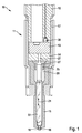
- the Indian Fig. 1 Area-wise illustrated fuel injector 10 is used for injecting fuel into the combustion chamber of an internal combustion engine, not shown.
- the fuel injector 10 is designed as a so-called common-rail injector for self-igniting internal combustion engines, wherein in the fuel injector 10, for example, a system pressure of more than 2000bar prevails.
- the fuel injector 10 has a multi-part injector housing 11.
- the injector housing 11 comprises in particular a holding body 12, a valve plate 13 adjoining it in the axial direction on the side facing the combustion chamber, a throttle plate 14 and a nozzle body 15.
- In the nozzle body 15 is at least one, but in practice a plurality of injection ports 16 for Injection of fuel formed in the combustion chamber of the internal combustion engine.
- the nozzle body 15 is partially radially surrounded by a nozzle retaining nut 17 which clamps the nozzle body 15 under axial intermediate position of the valve plate 13 and the throttle plate 14 against the holding body 12, as is known from the prior art per se.
- a high-pressure chamber 20 is formed, in which fuel under system pressure fuel can be stored. Further, within the high-pressure chamber 20, a nozzle needle 22 arranged in a liftable manner in the direction of the double arrow 21 is arranged as an injection member. In the in the Fig. 1 shown position, the nozzle needle 22 is in its lowered position, in which this rests on the inside of the nozzle body 15 to form a sealing seat and thereby at least indirectly closes the injection ports 16, to inject fuel into the combustion chamber of To avoid internal combustion engine. In her raised, in the Fig. 1 unrecognizable position, the nozzle needle 22, the injection ports 16 free, so that fuel is discharged from the high-pressure chamber 20 via the injection ports 16 into the combustion chamber of the internal combustion engine.
- the supply of the high-pressure chamber 20 with fuel under system pressure takes place in a manner known per se by a high-pressure bore, not shown in the figures, formed in the injector housing 11.
- the injection ports 16 opposite the end of the nozzle needle 22 is disposed radially within a valve member 25, which in turn is axially against the valve plate 13 facing away from the end face of the throttle plate 14 is supported.
- a control chamber 26 is formed, which serves in a known manner, the control of the lifting movement of the nozzle needle 22.
- the control chamber 26 via a in the Fig. 1 merely indicated drain hole 27 in a low pressure region of the injector 11 pressure relieved. This is done via a in the Fig. 1 also not shown valve element which can be controlled for example by means of a solenoid actuator or by means of a piezoelectric actuator and serves to open the drain hole 27 and close.
- the sensor device 30 additionally serves to detect the opening time of the nozzle needle 22.
- the sensor device 30 has a sensor element 31, which is in the form of a Piezoelectric element is formed.
- the sensor element 31 is designed to detect structure-borne noise, as typically occurs when the nozzle needle 22 encounters its sealing seat within the nozzle body 15 when the injection openings 16 are closed.
- the pressure relief of the control chamber 26 is detected via a structure-borne noise measurement, in which the taking place by releasing the drain hole 27 pressure reduction in the control chamber 26 is detected.
- the sensor element 31 is located with a sensitive to the measurement of structure-borne sound contact surface 34 on a contact surface 35 which formed by the holder body 12 facing end face of the valve plate 13 is.
- the recess 33 is formed in the illustrated embodiment as a bore with a circular cross-sectional area and disposed at a distance a from a fuel-carrying portion 36 of the injector 11.
- a further recess 41 also passes as a through hole having a relatively small cross-section, which serves to receive an electrical connection line 42 for the sensor element 31.
- the connecting line 42 can be designed, for example, in the form of enameled wires, so that the diameter or cross section of the connecting line 42 is as small as possible.
- the connecting line 42 is guided in a manner not shown, for example in the region of the connector of the fuel injector 10, so that at the same time the electrical contact of the fuel injector 10, the sensor element 31 is electrically contacted.
- a spring element 45 is supported in the form of a compression spring 46 from.
- the compression spring 46 is electrically insulated from the sensor element 31 and the injector housing 11, so that the injector housing 11 can serve as electrical ground for the sensor element 31.
- the spring element 45 is arranged under pretension between the base 39 and the sensor element 31, that in which in the Fig.
- the fuel injector 10 described so far can be modified or modified in many ways, without departing from the spirit of the invention.
- a non-conductive elastomer instead of a compression spring 46 as a spring element 45, which is arranged under prestress in the recess 33.
Landscapes
- Engineering & Computer Science (AREA)
- Chemical & Material Sciences (AREA)
- Analytical Chemistry (AREA)
- Combustion & Propulsion (AREA)
- Mechanical Engineering (AREA)
- General Engineering & Computer Science (AREA)
- Fuel-Injection Apparatus (AREA)
Abstract
Description
- Die Erfindung betrifft einen Kraftstoffinjektor nach dem Oberbegriff des Anspruchs 1. Ferner betrifft die Erfindung ein Verfahren zur Erkennung zumindest des Schießzeitpunkts eines Einspritzglieds in einem Kraftstoffinjektor mittels einer Sensoreinrichtung.
- Ein Kraftstoffinjektor nach dem Oberbegriff des Anspruchs 1 ist aus der
DE 10 2011 090 004 A1 der Anmelderin bekannt. Der bekannte Kraftstoffinjektor weist an der einer Einspritzöffnung abgewandten Seite seines Injektorgehäuses eine als Sacklochbohrung ausgebildete Ausnehmung auf. Die Ausnehmung ist an einer äußeren Stirnfläche des Injektorgehäuses ausgebildet und dient der Aufnahme eines als Piezoelement ausgebildeten Sensorelements. Mittels des Sensorelements lässt sich aufgrund einer Messung des Spannungssignals auf den Schließzeitpunkt eines Einspritzglieds (Düsennadel) schließen. Hierzu werden Körperschallsignale ausgewertet, welches beim Auftreffen des Einspritzglieds in ihren Sitz im Injektorgehäuse erzeugt werden. Die Erfassung des Schließzeitpunkts des Einspritzglieds dient dazu, insbesondere über die Lebensdauer des Kraftstoffinjektors betrachtet, den Einspritzzeitpunkt bzw. die Einspritzdauer des Kraftstoffinjektors zur Optimierung beispielsweise der Abgaswerte anzupassen. Einzelheiten bezüglich der Art und Weise, wie das Sensorelement innerhalb der Ausnehmung aufgenommen bzw. angeordnet ist, sind der genannten Schrift nicht entnehmbar. Darüber hinaus ist es aus dem Stand der Technik bekannt, Sensorelemente mittels einer Kleberschicht in Wirkverbindung beispielsweise mit einem Injektorgehäuse anzuordnen. Nachteilig bei derartigen Klebeverbindungen ist insbesondere die Beständigkeit der Klebeverbindung über die Lebensdauer des Kraftstoffinjektors betrachtet aufgrund des Auftretens relativ hoher Temperaturen und aufgrund von Medieneinflüssen. - Ausgehend von dem dargestellten Stand der Technik liegt der Erfindung die Aufgabe zugrunde, einen Kraftstoffinjektor nach dem Oberbegriff des Anspruchs 1 derart weiterzubilden, dass über die Lebensdauer des Kraftstoffinjektors betrachtet eine stets zuverlässige und genaue Erfassung des Schließzeitpunkts des Einspritzglieds ermöglicht wird.
- Diese Aufgabe wird erfindungsgemäß bei einem Kraftstoffinjektor mit den kennzeichnenden Merkmalen des Anspruchs 1 dadurch gelöst, dass das Sensorelement unter axialer Vorspannung gegen eine Kontaktfläche anliegt. Es wird somit insbesondere keine Klebeverbindung mit den beschriebenen Nachteilen zur Kopplung bzw. Verbindung des Sensorelements mit dem Injektorgehäuse bzw. mit der in dem Injektorgehäuse angeordneten Ausnehmung verwendet. Vielmehr findet über die axiale Vorspannung, die das Sensorelement gegen eine Kontaktfläche der Ausnehmung oder eines Bauteils des Kraftstoffinjektors drückt, eine über die Lebensdauer des Kraftstoffinjektors betrachtet zuverlässige Übertragung von Körperschall von dem Kraftstoffinjektor auf das Sensorelement statt.
- Vorteilhafte Weiterbildungen des erfindungsgemäßen Kraftstoffinjektors sind in den Unteransprüchen angeführt.
- In besonders bevorzugter konstruktiver Umsetzung der erfindungsgemäßen Lehre ist es vorgesehen, dass die axiale Vorspannung mittels eines Federelements einstellbar ist. Dabei wird je nach Dimensionierung des Federelements die benötigte Anlagekraft auf das Sensorelement erzielt.
- In Weiterbildung des zuletzt genannten Vorschlags ist es vorgesehen, dass das Federelement als Druckfeder ausgebildet ist, die sich zwischen einer der Kontaktfläche abgewandten Seite des Sensorelements und einem Gehäuseelement des Injektorgehäuses abstützt. Eine derartige konstruktive Ausgestaltung hat insbesondere den Vorteil einer relativ einfachen Montage des Federelements, da diese nicht durch zusätzliche, separate Befestigungselemente gesichert bzw. befestigt werden muss, sondern alleine durch den jeweils stirnseitigen Anlagekontakt zwischen dem Gehäuseelement und dem Sensorelement in seiner dafür vorgesehenen Position positioniert ist.
- Um insbesondere einen größtmöglichen Schutz des Sensorelements vor äußeren mechanischen Einflüssen sowie vor Umwelteinflüssen zu ermöglichen, ist es in einer weiteren bevorzugten Ausgestaltung der Erfindung vorgesehen, dass die Ausnehmung, ggf. mit Ausnahme einer weiteren Ausnehmung zur Aufnahme einer elektrischen Anschlussleitung für das Sensorelement, vollständig innerhalb des Injektorgehäuses angeordnet ist.
- Insbesondere bei einer Anordnung des Sensorelements in einem Kraftstoffinjektor, der als Common-Rail-Injektor ausgebildet ist, herrschen im Injektorgehäuse sehr hohe Drücke von beispielsweise mehr als 2000bar. Um das Sensorelement für derartige Anwendungen konstruktiv möglichst einfach gestalten zu können, das heißt möglichst keine zusätzlichen Dichtmaßnahmen vorsehen zu müssen, ist es vorgesehen, dass die Ausnehmung gegenüber einem kraftstoffführenden Bereich, insbesondere einem Hochdruckbereich des Kraftstoffinjektors, mediendicht ausgebildet ist.
- Für die Erfassung des Körperschalls kann es von Vorteil sein, das Sensorelement möglichst nahe an der Quelle des Körperschalls anzuordnen. Darüber hinaus ist es insbesondere bei einer innerhalb des Injektorgehäuses angeordneten Ausnehmung zur Aufnahme des Sensorelements von Vorteil, wenn diese fertigungstechnisch relativ einfach realisiert werden kann. Daher ist es in einer weiteren bevorzugten Ausgestaltung der Erfindung vorgesehen, dass die Ausnehmung im Bereich eines Haltekörpers des Injektorgehäuses auf der einer Ventilplatte zugewandten Seite als eine in einer Stirnfläche des Haltekörpers ausgebildete Sacklochbohrung ausgebildet ist. Bei einer derartigen Anordnung bzw. Ausbildung der Ausnehmung wird die Kontaktfläche insbesondere unmittelbar von einer Stirnfläche der Ventilplatte gebildet. Bei der Ausbildung der Kontaktfläche muss lediglich darauf geachtet werden, dass ein hinreichender Kontakt zwischen dem Sensorelement und der Ventilplatte ausgebildet wird. Dies wird beispielsweise durch eine entsprechende geringe Rauigkeit der Kontaktfläche erzielt, welche aber üblicherweise bei dem zur Diskussion stehenden Ventilplatten, wie Sie üblicherweise bei derartigen Kraftstoffinjektoren verwendet werden, gegeben ist.
- Um einerseits die benötigte Anlagekraft des Sensorelements gegen die Kontaktfläche zu ermöglichen, und andererseits insbesondere möglichst wenig zusätzliche Montageschritte zur Erzeugung der axialen Anlagekraft durchführen zu müssen, ist es darüber hinaus bevorzugt vorgesehen, dass die Ventilplatte mittels einer Düsenspannmutter axial zumindest mittelbar gegen den Haltekörper verspannt ist.
- Die Erfindung umfasst auch ein Verfahren zur Erkennung zumindest des Schließzeitpunkts eines Einspritzglieds in einem Kraftstoffinjektor mittels einer Sensoreinrichtung, wobei der Kraftstoffinjektor entsprechend den obigen Anmerkungen erfindungsgemäß gestaltet ist. Ein derartiges erfindungsgemäßes Verfahren zeichnet sich dadurch aus, dass zusätzlich auch der Öffnungszeitpunkt des Einspritzglieds erfasst wird. Ein derartiges Verfahren ermöglicht eine noch genauere Erfassung der Einspritzparameter bzw. eine optimierte Ansteuerung des Einspritzglieds.
- In bevorzugter Ausgestaltung des erfindungsgemäßen Verfahrens erfolgt die Erfassung des Öffnungszeitpunkts des Einspritzglieds aufgrund einer Druckabsenkung in einem Steuerraum im Injektorgehäuse. Insbesondere hebt zur Druckabsenkung in dem Steuerraum ein entsprechendes Ventilglied von einem Sitz ab und ermöglicht ein Abströmen von Kraftstoff aus dem Steuerraum in einen Niederdruckbereich des Kraftstoffinjektors, wodurch Körperschallsignale erzeugt werden, die mittels der Sensoreinrichtung einen Rückschluss auf den Öffnungszeitpunkt des Einspritzglieds ermöglichen.
- Weitere Vorteile, Merkmale und Einzelheiten der Erfindung ergeben sich aus der nachfolgenden Beschreibung bevorzugter Ausführungsbeispiele sowie anhand der Zeichnung.
- Diese zeigt in:
- Fig. 1
- einen Teilbereich eines erfindungsgemäßen Kraftstoffinjektors im Längsschnitt,
- Fig. 2
- ein Detail der
Fig. 1 in vergrößerter Darstellung und - Fig. 3
- eine perspektivische Ansicht auf einen Haltekörper, wie er bei einem Kraftstoffinjektor entsprechend der
Fig.1 und2 verwendet wird. - Gleiche Elemente bzw. Elemente mit gleicher Funktion sind in den Figuren mit den gleichen Bezugsziffern versehen.
- Der in der
Fig. 1 bereichsweise dargestellte erfindungsgemäße Kraftstoffinjektor 10 dient dem Einspritzen von Kraftstoff in den Brennraum einer nicht gezeigten Brennkraftmaschine. Insbesondere ist der Kraftstoffinjektor 10 als sogenannter Common-Rail-Injektor für selbstzündende Brennkraftmaschinen ausgebildet, wobei in dem Kraftstoffinjektor 10 beispielsweise ein Systemdruck von mehr als 2000bar herrscht. - Der Kraftstoffinjektor 10 weist ein mehrteilig ausgebildetes Injektorgehäuse 11 auf. Das Injektorgehäuse 11 umfasst insbesondere einen Haltekörper 12, eine sich in axialer Richtung auf der dem Brennraum zugewandten Seite sich daran anschließende Ventilplatte 13, eine Drosselplatte 14 sowie einen Düsenkörper 15. In dem Düsenkörper 15 ist wenigstens eine, in der Praxis jedoch mehrere Einspritzöffnungen 16 zum Einspritzen von Kraftstoff in den Brennraum der Brennkraftmaschine ausgebildet. Der Düsenkörper 15 ist bereichsweise von einer Düsenspannmutter 17 radial umfasst, die den Düsenkörper 15 unter axialer Zwischenlage der Ventilplatte 13 und der Drosselplatte 14 gegen den Haltekörper 12 verspannt, wie dies aus dem Stand der Technik an sich bekannt ist.
- Innerhalb des Düsenkörpers 15 ist ein Hochdruckraum 20 ausgebildet, in dem unter Systemdruck stehender Kraftstoff speicherbar ist. Ferner ist innerhalb des Hochdruckraums 20 eine in Richtung des Doppelpfeils 21 hubbeweglich angeordnete Düsennadel 22 als Einspritzglied angeordnet. In der in der
Fig. 1 dargestellten Stellung befindet sich die Düsennadel 22 in ihrer abgesenkten Position, bei der diese an der Innenseite des Düsenkörpers 15 unter Ausbildung eines Dichtsitzes anliegt und dabei zumindest mittelbar die Einspritzöffnungen 16 verschließt, um ein Einspritzen von Kraftstoff in den Brennraum der Brennkraftmaschine zu vermeiden. In ihrer angehobenen, in derFig. 1 nicht erkennbaren Position gibt die Düsennadel 22 die Einspritzöffnungen 16 frei, so dass Kraftstoff aus dem Hochdruckraum 20 über die Einspritzöffnungen 16 in den Brennraum der Brennkraftmaschine abgegeben wird. Die Versorgung des Hochdruckraums 20 mit unter Systemdruck stehendem Kraftstoff findet auf an sich bekannte Art und Weise durch eine in den Figuren nicht dargestellte, in dem Injektorgehäuse 11 ausgebildete Hochdruckbohrung statt. - Das den Einspritzöffnungen 16 gegenüberliegende Ende der Düsennadel 22 ist radial innerhalb eines Ventilstücks 25 angeordnet, das sich seinerseits axial gegen die der Ventilplatte 13 abgewandte Stirnfläche der Drosselplatte 14 abstützt. Innerhalb des Ventilstücks 25 ist ein Steuerraum 26 ausgebildet, der in bekannter Art und Weise der Steuerung der Hubbewegung der Düsennadel 22 dient. Hierzu ist der Steuerraum 26 über eine in der
Fig. 1 lediglich angedeutete Ablaufbohrung 27 in einen Niederdruckbereich des Injektorgehäuses 11 druckentlastbar. Dies erfolgt über einen in derFig. 1 ebenfalls nicht gezeigtes Ventilelement, das beispielsweise mittels eines Magnetaktuators oder aber mittels eines Piezoaktuators ansteuerbar ist und dazu dient, die Ablaufbohrung 27 zu öffnen bzw. zu schließen. - Erfindungswesentlich ist eine innerhalb des Injektorgehäuses 11 angeordnete Sensoreinrichtung 30 zur Erkennung zumindest des Schließzeitpunkts der Düsennadel 22. Im dargestellten Ausführungsbeispiel dient die Sensoreinrichtung 30 darüber hinaus zusätzlich der Erkennung des Öffnungszeitpunkts der Düsennadel 22. Die Sensoreinrichtung 30 weist ein Sensorelement 31 auf, das in Form eines Piezoelements ausgebildet ist. Insbesondere ist das Sensorelement 31 dazu ausgebildet, Körperschall zu detektieren, wie er typischerweise beim Aufreffen der Düsennadel 22 auf ihren Dichtsitz innerhalb des Düsenkörpers 15 beim Verschließen der Einspritzöffnungen 16 auftritt. Darüber hinaus wird auch die Druckentlastung des Steuerraums 26 über eine Körperschallmessung detektiert, in der der durch das Freigeben der Ablaufbohrung 27 stattfindende Druckabbau im Steuerraum 26 erfasst wird.
- Zur Aufnahme des Sensorelement 31 im Injektorgehäuse 11 weist der Haltekörper 12 auf der der Ventilplatte 13 zugewandten Stirnfläche eine sacklochförmige Ausnehmung 33 auf, deren Tiefe t größer ist als die Höhe h des Sensorelements 31. Das Sensorelement 31 liegt mit einer zur Messung des Körperschalls sensitiven Anlagefläche 34 flächig an einer Kontaktfläche 35 auf, die von der dem Haltekörper 12 zugewandten Stirnfläche der Ventilplatte 13 gebildet ist. Wie insbesondere anhand der
Fig. 3 erkennbar ist, ist die Ausnehmung 33 im dargestellten Ausführungsbeispiel als Bohrung mit einer runden Querschnittsfläche ausgebildet und in einem Abstand a von einem kraftstoffführenden Bereich 36 des Injektorgehäuses 11 angeordnet. Der Abstand a bewirkt zusammen mit einer ebenen Stirnfläche 37 des Haltekörpers 12 im Bereich der Ausnehmung 33 sowie durch die entsprechende axiale Spannkraft der Ventilplatte 13 gegen den Haltekörper 12 durch die Düsenspannmutter 17, dass kein unter Druck stehender Kraftstoff in den Bereich der Ausnehmung 33 gelangt, der Bereich somit mediendicht ausgebildet ist. - Vom Grund 39 der Ausnehmung 33 geht darüber hinaus eine weitere Ausnehmung 41 als eine einen relativ geringen Querschnitt aufweisende Durchgangsbohrung aus, die der Aufnahme einer elektrischen Anschlussleitung 42 für das Sensorelement 31 dient. Die Anschlussleitung 42 kann dabei beispielsweise in Form von Lackdrähten ausgebildet sein, damit der Durchmesser bzw. Querschnitt der Anschlussleitung 42 möglichst gering ist. Die Anschlussleitung 42 ist auf nicht gezeigte Art und Weise beispielsweise in dem Bereich des Anschlusssteckers des Kraftstoffinjektors 10 geführt, so dass bei der elektrischen Kontaktierung des Kraftstoffinjektors 10 gleichzeitig das Sensorelement 31 elektrisch kontaktiert wird.
- Zwischen dem Grund 39 der Ausnehmung 33 und der der Anlagefläche 34 abgewandten Stirnfläche des Sensorelements 31 stützt sich ein Federelement 45 in Form einer Druckfeder 46 ab. Für den Fall, dass lediglich eine einzige Anschlussleitung 42 verwendet wird, ist es von Vorteil, wenn die Druckfeder 46 zum Sensorelement 31 und zum Injektorgehäuse 11 elektrisch isoliert ist, sodass das Injektorgehäuse 11 als elektrische Masse für das Sensorelement 31 dienen kann. Das Federelement 45 ist unter Vorspannung derart zwischen dem Grund 39 und dem Sensorelement 31 angeordnet, dass in dem in den
Fig. 1 und2 dargestellten Einbauzustand des Sensorelements 31 in der Ausnehmung 33 über das Federelement 45 eine in Richtung des Pfeils 47 wirkende axiale Vorspannkraft auf das Sensorelement 31 ausgeübt wird, derart, dass die Anlagefläche 34 des Sensorelement 31 an der Kontaktfläche 35 derart anliegt, dass die angesprochenen Körperschallsignale detektiert werden können. - Bezüglich der Signalverarbeitung bzw. der Art und Weise, wie insbesondere der Schließzeitpunkt der Düsennadel 22 mittels einer derartigen Sensoreinrichtung 30 erfasst wird, wird auf die
DE 10 2011 090 004 A1 der Anmelderin verwiesen, die insofern Bestandteil dieser Anmeldung sein soll. - Der soweit beschriebene Kraftstoffinjektor 10 kann in vielfältiger Art und Weise abgewandelt bzw. modifiziert werden, ohne vom Erfindungsgedanken abzuweichen. So ist es beispielsweise denkbar, anstelle einer Druckfeder 46 als Federelement 45 ein nichtleitendes Elastomer zu verwenden, das unter Vorspannung in der Ausnehmung 33 angeordnet ist.
Claims (10)
- Kraftstoffinjektor (10), mit einem Injektorgehäuse (11), in dem ein Einspritzglied (22) zum Verschließen und Freigeben wenigstens einer im Injektorgehäuse (11) ausgebildeten Einspritzöffnung (16) hubbeweglich angeordnet ist, und mit einer Sensoreinrichtung (30) zur Erkennung zumindest des Schließzeitpunkts des Einspritzglieds (22), wobei die Sensoreinrichtung (30) ein als Piezoelement ausgebildetes Sensorelement (31) aufweist, das in einer Ausnehmung (33) des Injektorgehäuses (11) in Anlagekontakt mit dem Injektorgehäuse (11) angeordnet ist, und das dazu ausgebildet ist, den Schließzeitpunkt des Einspritzglieds (22) aufgrund eines Körperschallsignals zu detektieren,
dadurch gekennzeichnet,
dass das Sensorelement (31) unter axialer Vorspannung gegen eine Kontaktfläche (35) anliegt. - Kraftstoffinjektor nach Anspruch 1,
dadurch gekennzeichnet,
dass die axiale Vorspannung mittels eines Federelements (45) einstellbar ist. - Kraftstoffinjektor nach Anspruch 2,
dadurch gekennzeichnet,
dass das Federelement (45) als Druckfeder (46) ausgebildet ist, die sich zwischen einer der Kontaktfläche (35) abgewandten Seite des Sensorelements (31) und einem Gehäuseelement (12) des Injektorgehäuses (11) abstützt. - Kraftstoffinjektor nach einem der Ansprüche 1 bis 3,
dadurch gekennzeichnet,
dass die Ausnehmung (33) vollständig innerhalb des Injektorgehäuses (11) angeordnet ist
oder
dass die Ausnehmung (33) mit Ausnahme einer weiteren Ausnehmung (41) zur Aufnahme einer elektrischen Anschlussleitung (42) für das Sensorelement (31) vollständig innerhalb des Injektorgehäuses (11) angeordnet ist. - Kraftstoffinjektor nach einem der Ansprüche 1 bis 4,
dadurch gekennzeichnet,
dass die Ausnehmung (33) gegenüber einem kraftstoffführenden Bereich (36) des Injektorgehäuses (11) mediendicht ausgebildet ist. - Kraftstoffinjektor nach einem der Ansprüche 1 bis 5,
dadurch gekennzeichnet,
dass die Ausnehmung (33) im Bereich eines als Haltekörper ausgebildeten Gehäuseelements (12) des Injektorgehäuses (11) auf der einer Ventilplatte (13) zugewandten Seite als eine in einer Stirnfläche (37) des Gehäuseelements (12) angeordnete Sacklochbohrung ausgebildet ist. - Kraftstoffinjektor nach Anspruch 6,
dadurch gekennzeichnet,
dass die Kontaktfläche (35) von einer Stirnfläche der Ventilplatte (13) gebildet ist. - Kraftstoffinjektor nach Anspruch 6 oder 7,
dadurch gekennzeichnet,
dass die Ventilplatte (13) mittels einer Düsenspannmutter (17) axial zumindest mittelbar gegen das Gehäuseelement (12) verspannt ist. - Verfahren zur Erkennung zumindest des Schließzeitpunkts eines Einspritzglieds (22) in einem Kraftstoffinjektor (10) mittels einer Sensoreinrichtung (30), wobei der Kraftstoffinjektor (10) nach einem der Ansprüche 1 bis 8 ausgebildet ist,
dadurch gekennzeichnet,
dass zusätzlich der Öffnungszeitpunkt des Einspritzglieds (22) erfasst wird. - Verfahren nach Anspruch 9,
dadurch gekennzeichnet,
dass die Erfassung des Öffnungszeitpunkts des Einspritzglieds (22) aufgrund einer Druckabsenkung in einem Steuerraum (26) im Injektorgehäuse (11) erfolgt.
Applications Claiming Priority (1)
| Application Number | Priority Date | Filing Date | Title |
|---|---|---|---|
| DE102014225894.4A DE102014225894A1 (de) | 2014-12-15 | 2014-12-15 | Kraftstoffinjektor und Verfahren zur Erkennung zumindest des Schließzeitpunkts eines Einspritzglieds |
Publications (2)
| Publication Number | Publication Date |
|---|---|
| EP3034854A1 true EP3034854A1 (de) | 2016-06-22 |
| EP3034854B1 EP3034854B1 (de) | 2018-06-27 |
Family
ID=54365167
Family Applications (1)
| Application Number | Title | Priority Date | Filing Date |
|---|---|---|---|
| EP15192634.2A Active EP3034854B1 (de) | 2014-12-15 | 2015-11-02 | Kraftstoffinjektor und verfahren zur erkennung zumindest des schliesszeitpunkts eines einspritzglieds |
Country Status (2)
| Country | Link |
|---|---|
| EP (1) | EP3034854B1 (de) |
| DE (1) | DE102014225894A1 (de) |
Cited By (1)
| Publication number | Priority date | Publication date | Assignee | Title |
|---|---|---|---|---|
| CN110052357A (zh) * | 2019-05-15 | 2019-07-26 | 哈尔滨工业大学 | 一种应用于高粘度流体喷射的阀门可调式压电微喷机构 |
Citations (3)
| Publication number | Priority date | Publication date | Assignee | Title |
|---|---|---|---|---|
| DE19813756A1 (de) * | 1998-03-27 | 1999-10-07 | Siemens Ag | Messung des Drucks eines Fluids |
| DE102009000741A1 (de) * | 2009-02-10 | 2010-08-12 | Robert Bosch Gmbh | Verfahren zum Bestimmen eines Nadelschließens |
| DE102011090004A1 (de) | 2011-12-28 | 2013-07-04 | Robert Bosch Gmbh | Verfahren und Anordnung zum Bestimmen eines Nadelschließens einer Ventilnadel |
-
2014
- 2014-12-15 DE DE102014225894.4A patent/DE102014225894A1/de not_active Withdrawn
-
2015
- 2015-11-02 EP EP15192634.2A patent/EP3034854B1/de active Active
Patent Citations (3)
| Publication number | Priority date | Publication date | Assignee | Title |
|---|---|---|---|---|
| DE19813756A1 (de) * | 1998-03-27 | 1999-10-07 | Siemens Ag | Messung des Drucks eines Fluids |
| DE102009000741A1 (de) * | 2009-02-10 | 2010-08-12 | Robert Bosch Gmbh | Verfahren zum Bestimmen eines Nadelschließens |
| DE102011090004A1 (de) | 2011-12-28 | 2013-07-04 | Robert Bosch Gmbh | Verfahren und Anordnung zum Bestimmen eines Nadelschließens einer Ventilnadel |
Cited By (1)
| Publication number | Priority date | Publication date | Assignee | Title |
|---|---|---|---|---|
| CN110052357A (zh) * | 2019-05-15 | 2019-07-26 | 哈尔滨工业大学 | 一种应用于高粘度流体喷射的阀门可调式压电微喷机构 |
Also Published As
| Publication number | Publication date |
|---|---|
| EP3034854B1 (de) | 2018-06-27 |
| DE102014225894A1 (de) | 2016-06-16 |
Similar Documents
| Publication | Publication Date | Title |
|---|---|---|
| EP2694795B1 (de) | Kraftstoffinjektor | |
| EP2640955B1 (de) | Kraftstoffinjektor | |
| EP3018337B1 (de) | Kraftstoffinjektor | |
| EP2918820A1 (de) | Kraftstoffinjektor, insbesondere Common-Rail-Injektor | |
| EP2918819A1 (de) | Kraftstoffinjektor, insbesondere Common-Rail-Injektor | |
| EP3001024B1 (de) | Kraftstoffinjektor und verwendung eines kraftstoffinjektors | |
| DE102014209324A1 (de) | Kraftstoffinjektor, insbesondere Common-Rail-Injektor | |
| EP3088729B1 (de) | Kraftstoffinjektor sowie vorrichtung und verfahren zur montage einer messeinrichtung | |
| EP3076002B1 (de) | Kraftstoffinjektor | |
| EP3034854B1 (de) | Kraftstoffinjektor und verfahren zur erkennung zumindest des schliesszeitpunkts eines einspritzglieds | |
| EP3018339B1 (de) | Injektor | |
| EP3111079B1 (de) | Kraftstoffinjektor | |
| EP2813698B1 (de) | Brennstoffeinspritzventil | |
| EP3076005B1 (de) | Kraftstoffinjektor und verfahren zum herstellen eines kraftstoffinjektors | |
| DE102015208488A1 (de) | Kraftstoffinjektor sowie Vorrichtung und Verfahren zur Montage einer Messeinrichtung | |
| EP3109453A1 (de) | Kraftstoffinjektor | |
| DE102018208318A1 (de) | Kraftstoffinjektor | |
| EP3176556B1 (de) | Sensorvorrichtung und kraftstoffinjektor mit einer sensorvorrichtung | |
| EP3181890A1 (de) | Sensorvorrichtung und kraftstoffinjektor mit einer sensorvorrichtung | |
| EP2985446B1 (de) | Injektor | |
| EP3056724A1 (de) | Kraftstoffinjektor und verfahren zur herstellung eines piezoelements für einen kraftstoffinjektor | |
| DE102014209997A1 (de) | Common-Rail-Injektor | |
| EP2002111A2 (de) | Kraftstoffinjektor | |
| EP1740821A1 (de) | Common-rail-injektor | |
| DE102015208069A1 (de) | Kraftstoffinjektor |
Legal Events
| Date | Code | Title | Description |
|---|---|---|---|
| PUAI | Public reference made under article 153(3) epc to a published international application that has entered the european phase |
Free format text: ORIGINAL CODE: 0009012 |
|
| AK | Designated contracting states |
Kind code of ref document: A1 Designated state(s): AL AT BE BG CH CY CZ DE DK EE ES FI FR GB GR HR HU IE IS IT LI LT LU LV MC MK MT NL NO PL PT RO RS SE SI SK SM TR |
|
| AX | Request for extension of the european patent |
Extension state: BA ME |
|
| 17P | Request for examination filed |
Effective date: 20161222 |
|
| RBV | Designated contracting states (corrected) |
Designated state(s): AL AT BE BG CH CY CZ DE DK EE ES FI FR GB GR HR HU IE IS IT LI LT LU LV MC MK MT NL NO PL PT RO RS SE SI SK SM TR |
|
| GRAP | Despatch of communication of intention to grant a patent |
Free format text: ORIGINAL CODE: EPIDOSNIGR1 |
|
| INTG | Intention to grant announced |
Effective date: 20180320 |
|
| GRAS | Grant fee paid |
Free format text: ORIGINAL CODE: EPIDOSNIGR3 |
|
| GRAA | (expected) grant |
Free format text: ORIGINAL CODE: 0009210 |
|
| AK | Designated contracting states |
Kind code of ref document: B1 Designated state(s): AL AT BE BG CH CY CZ DE DK EE ES FI FR GB GR HR HU IE IS IT LI LT LU LV MC MK MT NL NO PL PT RO RS SE SI SK SM TR |
|
| REG | Reference to a national code |
Ref country code: GB Ref legal event code: FG4D Free format text: NOT ENGLISH |
|
| REG | Reference to a national code |
Ref country code: AT Ref legal event code: REF Ref document number: 1012571 Country of ref document: AT Kind code of ref document: T Effective date: 20180715 |
|
| REG | Reference to a national code |
Ref country code: IE Ref legal event code: FG4D Free format text: LANGUAGE OF EP DOCUMENT: GERMAN |
|
| REG | Reference to a national code |
Ref country code: DE Ref legal event code: R096 Ref document number: 502015004813 Country of ref document: DE |
|
| PG25 | Lapsed in a contracting state [announced via postgrant information from national office to epo] |
Ref country code: LT Free format text: LAPSE BECAUSE OF FAILURE TO SUBMIT A TRANSLATION OF THE DESCRIPTION OR TO PAY THE FEE WITHIN THE PRESCRIBED TIME-LIMIT Effective date: 20180627 Ref country code: SE Free format text: LAPSE BECAUSE OF FAILURE TO SUBMIT A TRANSLATION OF THE DESCRIPTION OR TO PAY THE FEE WITHIN THE PRESCRIBED TIME-LIMIT Effective date: 20180627 Ref country code: NO Free format text: LAPSE BECAUSE OF FAILURE TO SUBMIT A TRANSLATION OF THE DESCRIPTION OR TO PAY THE FEE WITHIN THE PRESCRIBED TIME-LIMIT Effective date: 20180927 Ref country code: BG Free format text: LAPSE BECAUSE OF FAILURE TO SUBMIT A TRANSLATION OF THE DESCRIPTION OR TO PAY THE FEE WITHIN THE PRESCRIBED TIME-LIMIT Effective date: 20180927 Ref country code: FI Free format text: LAPSE BECAUSE OF FAILURE TO SUBMIT A TRANSLATION OF THE DESCRIPTION OR TO PAY THE FEE WITHIN THE PRESCRIBED TIME-LIMIT Effective date: 20180627 |
|
| REG | Reference to a national code |
Ref country code: NL Ref legal event code: MP Effective date: 20180627 |
|
| REG | Reference to a national code |
Ref country code: LT Ref legal event code: MG4D |
|
| PG25 | Lapsed in a contracting state [announced via postgrant information from national office to epo] |
Ref country code: RS Free format text: LAPSE BECAUSE OF FAILURE TO SUBMIT A TRANSLATION OF THE DESCRIPTION OR TO PAY THE FEE WITHIN THE PRESCRIBED TIME-LIMIT Effective date: 20180627 Ref country code: LV Free format text: LAPSE BECAUSE OF FAILURE TO SUBMIT A TRANSLATION OF THE DESCRIPTION OR TO PAY THE FEE WITHIN THE PRESCRIBED TIME-LIMIT Effective date: 20180627 Ref country code: GR Free format text: LAPSE BECAUSE OF FAILURE TO SUBMIT A TRANSLATION OF THE DESCRIPTION OR TO PAY THE FEE WITHIN THE PRESCRIBED TIME-LIMIT Effective date: 20180928 Ref country code: HR Free format text: LAPSE BECAUSE OF FAILURE TO SUBMIT A TRANSLATION OF THE DESCRIPTION OR TO PAY THE FEE WITHIN THE PRESCRIBED TIME-LIMIT Effective date: 20180627 |
|
| PG25 | Lapsed in a contracting state [announced via postgrant information from national office to epo] |
Ref country code: NL Free format text: LAPSE BECAUSE OF FAILURE TO SUBMIT A TRANSLATION OF THE DESCRIPTION OR TO PAY THE FEE WITHIN THE PRESCRIBED TIME-LIMIT Effective date: 20180627 |
|
| PG25 | Lapsed in a contracting state [announced via postgrant information from national office to epo] |
Ref country code: IS Free format text: LAPSE BECAUSE OF FAILURE TO SUBMIT A TRANSLATION OF THE DESCRIPTION OR TO PAY THE FEE WITHIN THE PRESCRIBED TIME-LIMIT Effective date: 20181027 Ref country code: EE Free format text: LAPSE BECAUSE OF FAILURE TO SUBMIT A TRANSLATION OF THE DESCRIPTION OR TO PAY THE FEE WITHIN THE PRESCRIBED TIME-LIMIT Effective date: 20180627 Ref country code: RO Free format text: LAPSE BECAUSE OF FAILURE TO SUBMIT A TRANSLATION OF THE DESCRIPTION OR TO PAY THE FEE WITHIN THE PRESCRIBED TIME-LIMIT Effective date: 20180627 Ref country code: SK Free format text: LAPSE BECAUSE OF FAILURE TO SUBMIT A TRANSLATION OF THE DESCRIPTION OR TO PAY THE FEE WITHIN THE PRESCRIBED TIME-LIMIT Effective date: 20180627 Ref country code: PL Free format text: LAPSE BECAUSE OF FAILURE TO SUBMIT A TRANSLATION OF THE DESCRIPTION OR TO PAY THE FEE WITHIN THE PRESCRIBED TIME-LIMIT Effective date: 20180627 Ref country code: CZ Free format text: LAPSE BECAUSE OF FAILURE TO SUBMIT A TRANSLATION OF THE DESCRIPTION OR TO PAY THE FEE WITHIN THE PRESCRIBED TIME-LIMIT Effective date: 20180627 |
|
| PG25 | Lapsed in a contracting state [announced via postgrant information from national office to epo] |
Ref country code: ES Free format text: LAPSE BECAUSE OF FAILURE TO SUBMIT A TRANSLATION OF THE DESCRIPTION OR TO PAY THE FEE WITHIN THE PRESCRIBED TIME-LIMIT Effective date: 20180627 Ref country code: IT Free format text: LAPSE BECAUSE OF FAILURE TO SUBMIT A TRANSLATION OF THE DESCRIPTION OR TO PAY THE FEE WITHIN THE PRESCRIBED TIME-LIMIT Effective date: 20180627 Ref country code: SM Free format text: LAPSE BECAUSE OF FAILURE TO SUBMIT A TRANSLATION OF THE DESCRIPTION OR TO PAY THE FEE WITHIN THE PRESCRIBED TIME-LIMIT Effective date: 20180627 |
|
| REG | Reference to a national code |
Ref country code: DE Ref legal event code: R097 Ref document number: 502015004813 Country of ref document: DE |
|
| PLBE | No opposition filed within time limit |
Free format text: ORIGINAL CODE: 0009261 |
|
| STAA | Information on the status of an ep patent application or granted ep patent |
Free format text: STATUS: NO OPPOSITION FILED WITHIN TIME LIMIT |
|
| PG25 | Lapsed in a contracting state [announced via postgrant information from national office to epo] |
Ref country code: DK Free format text: LAPSE BECAUSE OF FAILURE TO SUBMIT A TRANSLATION OF THE DESCRIPTION OR TO PAY THE FEE WITHIN THE PRESCRIBED TIME-LIMIT Effective date: 20180627 |
|
| 26N | No opposition filed |
Effective date: 20190328 |
|
| REG | Reference to a national code |
Ref country code: CH Ref legal event code: PL |
|
| PG25 | Lapsed in a contracting state [announced via postgrant information from national office to epo] |
Ref country code: LU Free format text: LAPSE BECAUSE OF NON-PAYMENT OF DUE FEES Effective date: 20181102 Ref country code: MC Free format text: LAPSE BECAUSE OF FAILURE TO SUBMIT A TRANSLATION OF THE DESCRIPTION OR TO PAY THE FEE WITHIN THE PRESCRIBED TIME-LIMIT Effective date: 20180627 |
|
| REG | Reference to a national code |
Ref country code: BE Ref legal event code: MM Effective date: 20181130 |
|
| REG | Reference to a national code |
Ref country code: IE Ref legal event code: MM4A |
|
| PG25 | Lapsed in a contracting state [announced via postgrant information from national office to epo] |
Ref country code: CH Free format text: LAPSE BECAUSE OF NON-PAYMENT OF DUE FEES Effective date: 20181130 Ref country code: SI Free format text: LAPSE BECAUSE OF FAILURE TO SUBMIT A TRANSLATION OF THE DESCRIPTION OR TO PAY THE FEE WITHIN THE PRESCRIBED TIME-LIMIT Effective date: 20180627 Ref country code: LI Free format text: LAPSE BECAUSE OF NON-PAYMENT OF DUE FEES Effective date: 20181130 |
|
| PG25 | Lapsed in a contracting state [announced via postgrant information from national office to epo] |
Ref country code: IE Free format text: LAPSE BECAUSE OF NON-PAYMENT OF DUE FEES Effective date: 20181102 |
|
| PG25 | Lapsed in a contracting state [announced via postgrant information from national office to epo] |
Ref country code: BE Free format text: LAPSE BECAUSE OF NON-PAYMENT OF DUE FEES Effective date: 20181130 Ref country code: AL Free format text: LAPSE BECAUSE OF FAILURE TO SUBMIT A TRANSLATION OF THE DESCRIPTION OR TO PAY THE FEE WITHIN THE PRESCRIBED TIME-LIMIT Effective date: 20180627 |
|
| PG25 | Lapsed in a contracting state [announced via postgrant information from national office to epo] |
Ref country code: MT Free format text: LAPSE BECAUSE OF FAILURE TO SUBMIT A TRANSLATION OF THE DESCRIPTION OR TO PAY THE FEE WITHIN THE PRESCRIBED TIME-LIMIT Effective date: 20180627 |
|
| PG25 | Lapsed in a contracting state [announced via postgrant information from national office to epo] |
Ref country code: TR Free format text: LAPSE BECAUSE OF FAILURE TO SUBMIT A TRANSLATION OF THE DESCRIPTION OR TO PAY THE FEE WITHIN THE PRESCRIBED TIME-LIMIT Effective date: 20180627 |
|
| PG25 | Lapsed in a contracting state [announced via postgrant information from national office to epo] |
Ref country code: PT Free format text: LAPSE BECAUSE OF FAILURE TO SUBMIT A TRANSLATION OF THE DESCRIPTION OR TO PAY THE FEE WITHIN THE PRESCRIBED TIME-LIMIT Effective date: 20180627 |
|
| PG25 | Lapsed in a contracting state [announced via postgrant information from national office to epo] |
Ref country code: CY Free format text: LAPSE BECAUSE OF FAILURE TO SUBMIT A TRANSLATION OF THE DESCRIPTION OR TO PAY THE FEE WITHIN THE PRESCRIBED TIME-LIMIT Effective date: 20180627 Ref country code: MK Free format text: LAPSE BECAUSE OF NON-PAYMENT OF DUE FEES Effective date: 20180627 Ref country code: HU Free format text: LAPSE BECAUSE OF FAILURE TO SUBMIT A TRANSLATION OF THE DESCRIPTION OR TO PAY THE FEE WITHIN THE PRESCRIBED TIME-LIMIT; INVALID AB INITIO Effective date: 20151102 |
|
| GBPC | Gb: european patent ceased through non-payment of renewal fee |
Effective date: 20191102 |
|
| PG25 | Lapsed in a contracting state [announced via postgrant information from national office to epo] |
Ref country code: GB Free format text: LAPSE BECAUSE OF NON-PAYMENT OF DUE FEES Effective date: 20191102 |
|
| REG | Reference to a national code |
Ref country code: AT Ref legal event code: MM01 Ref document number: 1012571 Country of ref document: AT Kind code of ref document: T Effective date: 20201102 |
|
| PG25 | Lapsed in a contracting state [announced via postgrant information from national office to epo] |
Ref country code: AT Free format text: LAPSE BECAUSE OF NON-PAYMENT OF DUE FEES Effective date: 20201102 |
|
| PGFP | Annual fee paid to national office [announced via postgrant information from national office to epo] |
Ref country code: FR Payment date: 20231123 Year of fee payment: 9 |
|
| PG25 | Lapsed in a contracting state [announced via postgrant information from national office to epo] |
Ref country code: FR Free format text: LAPSE BECAUSE OF NON-PAYMENT OF DUE FEES Effective date: 20241130 |
|
| PGFP | Annual fee paid to national office [announced via postgrant information from national office to epo] |
Ref country code: DE Payment date: 20260126 Year of fee payment: 11 |