EP3034768A1 - Fenster oder tür mit einer glasfalzverklebung - Google Patents
Fenster oder tür mit einer glasfalzverklebung Download PDFInfo
- Publication number
- EP3034768A1 EP3034768A1 EP15199695.6A EP15199695A EP3034768A1 EP 3034768 A1 EP3034768 A1 EP 3034768A1 EP 15199695 A EP15199695 A EP 15199695A EP 3034768 A1 EP3034768 A1 EP 3034768A1
- Authority
- EP
- European Patent Office
- Prior art keywords
- window
- glazing
- door according
- frame
- profile
- Prior art date
- Legal status (The legal status is an assumption and is not a legal conclusion. Google has not performed a legal analysis and makes no representation as to the accuracy of the status listed.)
- Granted
Links
Images


Classifications
-
- E—FIXED CONSTRUCTIONS
- E06—DOORS, WINDOWS, SHUTTERS, OR ROLLER BLINDS IN GENERAL; LADDERS
- E06B—FIXED OR MOVABLE CLOSURES FOR OPENINGS IN BUILDINGS, VEHICLES, FENCES OR LIKE ENCLOSURES IN GENERAL, e.g. DOORS, WINDOWS, BLINDS, GATES
- E06B3/00—Window sashes, door leaves, or like elements for closing wall or like openings; Layout of fixed or moving closures, e.g. windows in wall or like openings; Features of rigidly-mounted outer frames relating to the mounting of wing frames
- E06B3/04—Wing frames not characterised by the manner of movement
- E06B3/06—Single frames
- E06B3/08—Constructions depending on the use of specified materials
- E06B3/20—Constructions depending on the use of specified materials of plastics
- E06B3/22—Hollow frames
- E06B3/221—Hollow frames with the frame member having local reinforcements in some parts of its cross-section or with a filled cavity
- E06B3/222—Hollow frames with the frame member having local reinforcements in some parts of its cross-section or with a filled cavity with internal prefabricated reinforcing section members inserted after manufacturing of the hollow frame
-
- E—FIXED CONSTRUCTIONS
- E06—DOORS, WINDOWS, SHUTTERS, OR ROLLER BLINDS IN GENERAL; LADDERS
- E06B—FIXED OR MOVABLE CLOSURES FOR OPENINGS IN BUILDINGS, VEHICLES, FENCES OR LIKE ENCLOSURES IN GENERAL, e.g. DOORS, WINDOWS, BLINDS, GATES
- E06B3/00—Window sashes, door leaves, or like elements for closing wall or like openings; Layout of fixed or moving closures, e.g. windows in wall or like openings; Features of rigidly-mounted outer frames relating to the mounting of wing frames
- E06B3/54—Fixing of glass panes or like plates
- E06B3/5409—Means for locally spacing the pane from the surrounding frame
-
- E—FIXED CONSTRUCTIONS
- E06—DOORS, WINDOWS, SHUTTERS, OR ROLLER BLINDS IN GENERAL; LADDERS
- E06B—FIXED OR MOVABLE CLOSURES FOR OPENINGS IN BUILDINGS, VEHICLES, FENCES OR LIKE ENCLOSURES IN GENERAL, e.g. DOORS, WINDOWS, BLINDS, GATES
- E06B3/00—Window sashes, door leaves, or like elements for closing wall or like openings; Layout of fixed or moving closures, e.g. windows in wall or like openings; Features of rigidly-mounted outer frames relating to the mounting of wing frames
- E06B3/04—Wing frames not characterised by the manner of movement
- E06B3/06—Single frames
- E06B3/08—Constructions depending on the use of specified materials
- E06B3/20—Constructions depending on the use of specified materials of plastics
- E06B3/22—Hollow frames
- E06B3/221—Hollow frames with the frame member having local reinforcements in some parts of its cross-section or with a filled cavity
- E06B3/222—Hollow frames with the frame member having local reinforcements in some parts of its cross-section or with a filled cavity with internal prefabricated reinforcing section members inserted after manufacturing of the hollow frame
- E06B2003/225—Means for stabilising the insert
-
- E—FIXED CONSTRUCTIONS
- E06—DOORS, WINDOWS, SHUTTERS, OR ROLLER BLINDS IN GENERAL; LADDERS
- E06B—FIXED OR MOVABLE CLOSURES FOR OPENINGS IN BUILDINGS, VEHICLES, FENCES OR LIKE ENCLOSURES IN GENERAL, e.g. DOORS, WINDOWS, BLINDS, GATES
- E06B3/00—Window sashes, door leaves, or like elements for closing wall or like openings; Layout of fixed or moving closures, e.g. windows in wall or like openings; Features of rigidly-mounted outer frames relating to the mounting of wing frames
- E06B3/04—Wing frames not characterised by the manner of movement
- E06B3/263—Frames with special provision for insulation
- E06B3/2632—Frames with special provision for insulation with arrangements reducing the heat transmission, other than an interruption in a metal section
- E06B2003/26332—Arrangements reducing the heat transfer in the glazing rabbet or the space between the wing and the casing frame
-
- E—FIXED CONSTRUCTIONS
- E06—DOORS, WINDOWS, SHUTTERS, OR ROLLER BLINDS IN GENERAL; LADDERS
- E06B—FIXED OR MOVABLE CLOSURES FOR OPENINGS IN BUILDINGS, VEHICLES, FENCES OR LIKE ENCLOSURES IN GENERAL, e.g. DOORS, WINDOWS, BLINDS, GATES
- E06B3/00—Window sashes, door leaves, or like elements for closing wall or like openings; Layout of fixed or moving closures, e.g. windows in wall or like openings; Features of rigidly-mounted outer frames relating to the mounting of wing frames
- E06B3/54—Fixing of glass panes or like plates
- E06B3/58—Fixing of glass panes or like plates by means of borders, cleats, or the like
- E06B3/62—Fixing of glass panes or like plates by means of borders, cleats, or the like of rubber-like elastic cleats
- E06B2003/6217—Fixing of glass panes or like plates by means of borders, cleats, or the like of rubber-like elastic cleats with specific fixing means
- E06B2003/6223—Fixing of glass panes or like plates by means of borders, cleats, or the like of rubber-like elastic cleats with specific fixing means with protruding parts anchored in grooves
-
- E—FIXED CONSTRUCTIONS
- E06—DOORS, WINDOWS, SHUTTERS, OR ROLLER BLINDS IN GENERAL; LADDERS
- E06B—FIXED OR MOVABLE CLOSURES FOR OPENINGS IN BUILDINGS, VEHICLES, FENCES OR LIKE ENCLOSURES IN GENERAL, e.g. DOORS, WINDOWS, BLINDS, GATES
- E06B3/00—Window sashes, door leaves, or like elements for closing wall or like openings; Layout of fixed or moving closures, e.g. windows in wall or like openings; Features of rigidly-mounted outer frames relating to the mounting of wing frames
- E06B3/54—Fixing of glass panes or like plates
- E06B3/58—Fixing of glass panes or like plates by means of borders, cleats, or the like
- E06B3/5807—Fixing of glass panes or like plates by means of borders, cleats, or the like not adjustable
- E06B3/5821—Fixing of glass panes or like plates by means of borders, cleats, or the like not adjustable hooked on or in the frame member, fixed by clips or otherwise elastically fixed
Definitions
- the present invention relates to a window or a door with a Glasfalzverklebung according to the preamble of claim 1.
- Glazing seam bonds are known from the prior art. So will in the EP 1 373 672 B1 a wing for a window or a door is disclosed, wherein in the region of one of the folding surface of the sash facing cover glass of the glazing at a distance in front of the rebate a circumferentially extending boundary web is provided for the adhesive layer.
- the frame profile should be suitable for the installation of insulating glazing with different glazing thicknesses. This is achieved in that a plurality of transversely to the profile extension spaced apart side by side and arranged along the profile extension webs or lips is arranged on the rebate base of the frame profile, which can limit the introduction of adhesive, so that only the respectively required amount of adhesive is filled and the adhesive layer extends only to a defined position in the rabbet base. According to the invention, a pane of insulating glazing of adhesive remains unwetted.
- the webs or lips As a material for the webs or lips he is a material, such as an elastomer provided.
- the frame profile and the webs or lips are subsequently applied, for example by extrusion on the frame profile.
- the webs or lips may also be made of the same material as the frame profile.
- EP 2 639 395 A1 is the complete gluing of the insulating glass pane.
- EP 2 639 395 A1 is the production of the webs or lips of an elastomeric material in a separate manufacturing step consuming and therefore expensive.
- the frame profile for the insulating glazing to be installed must first be prepared. This happens, for example, by cutting excess webs or lips from the frame profile and is therefore time-consuming and therefore expensive.
- EP 2 685 043 A1 discloses a wing of a window or door and a glazing block, and a method of making the same.
- the glazing block has an adhesive reservoir filled with adhesive.
- the glazing and the frame rebate of the wing are connected to one another in each case only in the area of the glazing blocks inserted in the frame rebate.
- the adhesive is placed in the adhesive reservoir after mounting the glazing blocks.
- glazing blocks ensures that the static loads of a glazing are optimally distributed in a frame, thereby influencing or ensuring the proper functioning of the glider.
- the glazing blocks are to be aligned in the rebate base of the frame profile or to adjust its position. This is usually done in an iterative process, which, however, is adversely affected if the adhesive has already been activated.
- the object of the invention is to provide a window or door with improved glazing rebate bonding.
- a window or door is provided with a frame of interconnected portions of a frame profile, said frame having and forming a glazing rebate in which at least one glazing element is attached for gluing a glazing which forms an adhesive reservoir in the installed state in interaction with the frame profile and the glazing in the glazing rebate, wherein the glazing rebate element has a pad which is wholly or partially made of a resilient material.
- the Glasfalzelement on the pad which is made wholly or partly of a resilient material.
- the invention is therefore based on the idea to create a Glasfalzelement for a Glasfalzverklebung that assumes no other function due to its resilient properties than in its assembled state in conjunction with the Glasfalz form an adhesive reservoir through which the Glasfalzverklebung a glazing.
- the bond can be formed at a fixed glazing on the frame or in a window with a movable wing on the sash.
- sections on the pad shell advantageously prevents excess adhesive from the adhesive reservoir on the glasstalteleistenzugewandte side of Glasfalzes passes or excess adhesive can flow through in the direction of Glashaltemann. This is the case because the contour of the shell is guided to the height level of the Glasfalzes that the shell contacts the bottom of the Glasfalzes or the associated sash profile or the associated frame profile in this area and a flow of excess adhesive in this direction the glass retaining strip thereby prevented.
- the shell does not contact the bottom of the glass fold in the mounted state of the glass folding element on the glasstalteleistenabgewandten side of the shell.
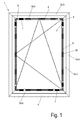
- a window 1a is shown.
- a window 1 a is described for the sake of simplicity.
- he can be replaced by the concept of the window but by the door.
- the following description also applies analogously to doors.
- the window 1a has a frame 2a and a sash 3a.
- the frame 2 a is composed here of mitred sections of a frame profile 4 a.
- the wing frame 3a is also composed here of mitred sections of a sash profile 5a.
- the window frame 2a would possibly not be circumferentially closed but open on one side.
- the casement profile 5a has a glass fold 6a.
- the circumferential glass fold 6a of the sash 3a has glazing blocks 7 on its vertical side and on its horizontal side.
- Fig. 1 also schematically shows fitting parts 8 such as locking bars or Eckumlenkept.
- the glazing blocks 7 are provided, which due to their properties for the support or for receiving and forwarding of static forces, in particular the weight forces of the glazing 9 are suitable.
- a glazing 9 is shown in a sash profile 5a.
- the casement profile 5a is-by way of example-a casement profile 5a, which is produced from a plastic material in an extrusion process.
- the sash profile 5a has a Z-shaped cross-sectional geometry, wherein the "Z" is rotated by 90 °.
- the sash profile 5a has a central hollow chamber 12.
- the central hollow chamber 12 has a reinforcing profile 13a, with which the area moment of inertia or the second order area moment of the wing frame profile 5a is increased, so that the wing frame profile 5a is stiffened by the reinforcing profile 13a.
- the reinforcing profile 13a is preferably made of a steel material by a forming process.
- the casement profile 5a also has further hollow chambers.
- the casement profile 5a also has a glass fold 6a.
- the sash part profile 5a has a located on the glass fold facing side of the sash profile 5a, vertically extending lug 14, the free end has a groove 15 into which a sealing profile 16 is inserted.
- the sealing profile 16 hugs in the assembled state of a window 1 a to the glazing 9 -here with dreischeibigen structure, in Fig. 2a before being installed in the glazing rebate 6a, thus sealing the glazing rebate 6a against the environment.
- the glass fold 6a has a block bridge 17 which is positioned and held in a groove 44 of the casement profile 5a and by a clip connection in the glass fold 6a.
- the sash part profile 5a further has a vertically extending projection 18 located on the side of the sash frame profile 5a facing away from the glass frame, the free end of which has a groove 19 into which a sealing profile 20 is inserted.
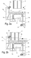
- Fig. 2b It is shown how the glazing block 7 is used to align the glazing 9 in the glazing rebate 6a.
- the glazing block 7 is positioned between the block bridge 17 and the glazing 9, so that it is ensured that the glazing 9 is inserted on all sides at a sufficient distance from the glazing rebate, the Attendance of the glazing 9 in the sash profile 5a is selected so that a sealing of the space between the panes of the glazing 9 and the spacer strips of the glazing is below the sealing profile 16 and an example of mitred sections of the sash profile 5a constructed sash 3a (not shown here) built-in glazing 9 is perfectly open.
- Fig. 2c the casement profile 5a is shown with inserted glazing 9 and inserted glazing block 7, on which the glazing 9 is supported.
- the installation of the glazing blocks 7 is usually done in an iteration process, so that the assembly step after Fig. 2b if necessary, repeated several times until the condition as in Fig. 2c represented, finally achieved.
- this assembly process is adversely affected when a Glasfalzverklebung according to the prior art in the field of Glazing blocks 7 to be made and the required adhesive has already been activated.
- the problem of possible contamination of the vertical surfaces of the sash 3a occurs when excess adhesive emerges from the glue reservoir of the glazing block 7.
- a window 1a is shown in section. To avoid repetition, in the following only additions, changes and deviations to the description of the FIGS. 2a to 2c described.
- Deviating from the illustration according to Fig. 2a to Fig. 2c has the casement profile 5a here a glass retaining strip 10a.
- the glass retaining strip 10a is latched via a projection 26 in a groove 27 of the wing frame profile 5a.
- the glass retaining strip 10a has two sealing lips 28, 29. The sealing lips 28, 29 nestle against the glazing 9 shown here and thus seal the glass rebate 6a against the environment.
- a glazing block 7 is arranged, on which the glazing 9 is supported.
- the window frame profile 4a has a central hollow chamber 21.
- the central hollow chamber 21 has a reinforcing profile 13c, with which the area moment of inertia or the second-order surface moment of the frame profile 4a is increased, so that the frame profile 4a is stiffened by the reinforcing profile 13c.
- the frame profile 4a also has further hollow chambers 22.
- the window frame profile 4a also has a glazing rebate 6c, which, however, is only used as a glazing rebate 6c in windows 1a, 1b without sash frames 3a, 3b.
- the window frame profile 4a has a on the glass fold facing side of the frame profile 4a located, vertically extending projection 23, the free end has a groove 24 into which a sealing profile 25 is inserted.
- the window frame profile 4a and the sash profile 5a form a folding area 11 in the closed state of the window 1a.
- a sealing profile 30 projects in a folding area 11 and is held in a groove 31 of the window frame profile 4a.
- the sealing profile 30 seals the folding area 11 together with the sealing profile 20 and the sealing profile 25 against the environment.
- the sealing profile 20 of the sash profile 5b and the sealing profile 25 of the frame profile 4a seal the rebate area 11 against the environment.
- the glazing rebate 6c of the frame profile 4a (not used here as a glazing rebate 6c, since a window is shown with a sash 3a, into which the glazing 9 is inserted,) has here two planes I, II.
- the two levels I, II have two different height levels.
- the plane I has a higher height level than the plane II, which is arranged here on the side of the window frame profile 4 a facing the glazing facet.
- the plane I has the groove 31 into which the sealing profile 30 is inserted.
- Fig. 4 is a sash profile 5b and a window frame profile 4b shown.
- the sash profile 5b or the frame profile 4b corresponds in its essential structural design to the frame profile 4a Fig. 3 , To repetitions to avoid, in the following only additions, changes and deviations from the description of the frame profile 4a after Fig. 3 described.
- the glass retaining strip 10b differs from the glass retaining strip 10a Fig. 3 a groove 32 into which a sealing profile 33 is inserted.
- the glass rebate 6b here has a bore with a conical countersink 34, which is penetrated by a screw 35.
- the screw 35 serves to fix the reinforcing profile 13b, which here has a U-shaped cross-sectional geometry and is designed as a profile with a closed contour.
- the reinforcing profile 13b is preferably made of a steel material by a forming process and a joining process.
- a glass folding element 36 is inserted between the casement profile 5b or the window frame profile 4b and the glazing 9.
- a sash 3b or a frame 2b shown here in each case in the form of the sash profile 5b or the frame profile 4b
- the glass folding element 36 has - at least in sections - a shell 37, which is arranged horizontally in the region of the glazing 9 and therefore is in contact with the glazing 9.
- the shell 37 On the glaskalteleistenzten side of the Glasfalzes 6b of the contour of the shell 37 is guided to the height level of the level II of the Glasfalzes 6b, so that the shell 37 the base of the Glasfalzes 6b or the sash profile 5b or the frame profile 4b contacted in this area.
- the shell 37 On the glasstalteleistenabgewandten side of the shell 37, the shell 37 extends beyond an outer glass pane 38 of the glazing 9 and ends here in a direction to the horizontal by 90 °, preferably larger as 30 ° in the direction of Glasfalzgrund angled free end 39 that does not contact the bottom of Glasfalzes 6b.
- the sash profile 5b has a Glashaltesteg 47 which is substantially parallel to the glazing 9 or parallel to the outer glass 38 of the glazing 9, integrally attached to the sash profile 5b on the glass fold facing side of the projection 23 of the sash profile 5b.
- the outer glass pane 38 of the glazing 9 has a distance a to the Glashaltesteg 47.
- the free end 39 of the shell 37 protrudes by at least 25% of the distance a between the glass retaining web 47 and the outer glass pane 38 of the glazing 9 - allowing a flow of adhesive - addition.
- the shell 37 is preferably made of a substrate, preferably made of a plastic material. Alternatively, the shell 37 may also be made of a metallic material.
- the glass folding element 36 has a pad 40.
- the pad 40 is preferably made of a wholly or partially compliant material. This material is more preferably elastic or partially elastic. The material further preferably has a foam-like structure. Foamed polyurethane is particularly preferably used as the material.
- the pad 40 is adhesively bonded to the shell 37 by gluing or, for example, in a common manufacturing process, such as e.g. a co-extrusion process with the shell 37 made.
- the Glasfalzelement 36 is advantageously made of a co-extruded profile, which is cut after the successful co-extrusion process to the required length for the Glasfalzelement 36.
- the shell 37 is connected in a form-fitting manner to the pad 40.
- the positive connection can be combined with the cohesive connection in a further alternative embodiment variant of the glass folding element 36.
- the pad 40 due to its yielding properties as well as due to its foam-like structure, accordingly Having cavities, is not designed to take in static relevant to the statics of the window forces without significant deformation of the pad 40 or transfer, so that the Glasfalzelement 36 is not designed to support the weight forces of the glazing 9 on the whole ,
- the pad 40 of the Glasfalziatas 36 has on its base of the glass fold 6b side facing a plurality of ribs 41, which are spaced by recesses 42.
- the recesses 42 take on a deformation of the pad 40 by the deformation displaced cushion material and thus improve the due to the foam-like structure of the material anyway high elasticity of the pad 40, so that -as in Fig. 5a the glass folding element 36 can also be used with the glass fold 6b with a plurality of planes I, II having different height levels, the shell 37 of the glass folding element 36 being horizontally aligned, or resting against the glazing 9 or touching it in a surface contact.
- the Glasfalzelement 36 has an opening 43.
- the aperture 43 forms in the assembled state of the Glasfalzelements 36 an adhesive reservoir.
- the breakthrough 43 here purely exemplarily has a D-shaped geometry.
- the aperture 43 may also have another suitable geometry.
- the width b of the aperture 43 is at least 1% of the total width B of the Glasfalz elements 36, preferably the width b of the aperture greater than 25% of the total width B of the Glasfalzides 36. It is essential to the invention that the opening 43 with respect to the shell 37 through the Shell 37 is limited, so that in the assembled state of Glasfalzides 36, an adhesive reservoir with closed outer boundary is created.
- a flow of excess adhesive on the glasstalteleistenabgewandten side of Glasfalzes 6b or a flow of excess adhesive in the direction of glass retaining strip 10b is prevented by the contour of the shell 37, which is guided to the height level of the level II of the Glasfalzes 6d, so that the shell 37, the bottom of the glazing rebate 6b or the sash frame profile 5b or the sash profile 4b contacts the bottom of the glazing rebate 6b in a region with respect to a direction of flow in the direction of the glazing bead 10b behind the glazing and a flow of excess adhesive therethrough in the direction of the glazing bead 10b prevented.
- the Glasfalzelement 36 is always used after the final blocking of the glazing with glazing blocks 7 in the Glasfalz 6b, which is due to the elasticity of the Glasfalzelements 36 readily possible. As a result, the assembly process of the glazing blocks 7 is not hindered.
- the filling of the adhesive reservoir formed by the opening 43 in conjunction with the bottom of the Glasfalzes 6b with adhesive takes place either during the assembly process of Glasfalzides 36 directly or after successful assembly process of Glasfalz elements 36 through an opening 45 in the shell 37, here - purely exemplary with a circular cross-section, which opens into a channel 46 which extends in the pad 40 and opens into the opening 43, wherein the opening 45, if necessary, for example, with a plug provided for this purpose (not shown) can be closed.
- the opening 45 may have other cross-sectional geometries than circular.
- the Glasfalzelement 36 has a channel 46, via the adhesive obliquely from the side in the opening 43 and in the adhesive reservoir can be filled.
- the channel 46 is disposed in the pad 40.
- the adhesive is introduced or injected via an injection device into the opening 43 or into the adhesive reservoir.
- the injection device is for this purpose provided with a pointed free end, with which the pad 40 is pierced, so that an explicit opening 45 or a channel 46 for filling the opening 43 and the adhesive reservoir is not required.
Landscapes
- Engineering & Computer Science (AREA)
- Civil Engineering (AREA)
- Structural Engineering (AREA)
- Securing Of Glass Panes Or The Like (AREA)
Abstract
Description
- Die vorliegende Erfindung betrifft ein Fenster oder eine Tür mit einer Glasfalzverklebung nach dem Oberbegriff des Anspruchs 1.
- Glasfalzverklebungen sind aus dem Stand der Technik bekannt. So wird in der
EP 1 373 672 B1 wird ein Flügel für ein Fenster oder eine Tür offenbart, wobei im Bereich einer der Falzfläche des Flügelrahmens zugewandten Deckscheibe der Isolierverglasung mit Abstand vor der Falzfläche ein in Umfangsrichtung verlaufender Begrenzungssteg für die Klebstoffschicht vorgesehen ist. - In der
EP 2 639 395 A1 werden ein Rahmenprofil sowie ein Flügel eines Fensters oder einer Tür und ein Verfahren zu deren Herstellung beschrieben. Nach derEP 2 639 395 A1 soll das Rahmenprofil für den Einbau von Isolierverglasungen mit unterschiedlichen Verglasungsdicken geeignet sein. Dies wird dadurch erreicht, das auf dem Falzgrund des Rahmenprofils eine Mehrzahl von quer zur Profilerstreckung beabstandet nebeneinander angeordneten und sich längs der Profilerstreckung erstreckenden Stege oder Lippen angeordnet ist, welche die Einbringung von Klebstoff begrenzen können, so dass nur die jeweils benötigte Menge Klebstoff eingefüllt wird und sich die Klebstoffschicht nur bis zu einer definierten Position im Falzgrund erstreckt. Erfindungsgemäß bleibt dabei eine Scheibe einer Isolierverglasung von Klebstoff unbenetzt. Als Werkstoff für die Stege oder Lippen ist ein er Werkstoff, wie z.B. ein Elastomer vorgesehen. Das Rahmenprofil und die Stege oder Lippen sind nachträglich z.B. durch Extrudieren auf das Rahmenprofil aufgebracht. In einer alternativen Ausführungsform können die Stege oder Lippen auch materialeinheitlich mit dem Rahmenprofil hergestellt sein. - Nachteilig an den Lösung nach
EP 1 373 672 B1 bzw.EP 2 639 395 A1 ist die vollumfängliche Verklebung der Isolierglasscheibe. Bei der Lösung nachEP 2 639 395 A1 ist die Herstellung der Stege oder Lippen aus einem Elastomerwerkstoff in einem separaten Herstellungsschritt aufwendig und damit teuer. Bei der Montage muss darüber hinaus das Rahmenprofil für die zu montierenden Isolierverglasung zunächst vorbereitet werden. Dies geschieht z.B. durch Herausschneiden überschüssiger Stege oder Lippen aus dem Rahmenprofil und ist deshalb zeitintensiv und damit teuer. - Um diesen Nachteil zu beheben, wird in der
EP 2 685 043 A1 ein Flügel eines Fensters oder einer Tür und ein Verglasungsklotz sowie ein Verfahren zu dessen Herstellung offenbart. Der Verglasungsklotz weist ein mit Kleber gefülltes Klebstoffreservoir auf. Dadurch werden die Verglasung und der Rahmenfalz des Flügels jeweils nur im Bereich der in den Rahmenfalz eingelegter Verglasungsklötze stoffschlüssig miteinander verbunden. In einer alternativen Ausführungsform wird der Kleber nach Montage der Verglasungsklötze in das Klebstoffreservoir eingebracht. - Durch den Einsatz von Verglasungsklötzen wird sichergestellt, dass die statischen Lasten einer Verglasung optimal in einem Rahmen verteilt werden und dadurch die einwandfreie Funktionsfähigkeit des Flügels beeinflusst bzw. sichergestellt wird. Dazu sind die Verglasungsklötze jedoch im Falzgrund des Rahmenprofils auszurichten bzw. dessen Position zu justieren. Dies geschieht üblicherweise in einem Iterationsprozess, der jedoch dann nachteilig behindert wird, wenn der Kleber bereits aktiviert wurde.
- Bei dem Füllen des Klebstoffreservoirs nach Montage des Verglasungsklotzes ergibt sich das Problem einer möglichen Verschmutzung der vertikalen Rahmenprofilflächen, wenn überschüssiger Kleber aus dem Reservoir heraustritt und durch die Montage einer Glashalteleiste nach außen verdrängt wird.
- Die Erfindung hat ausgehend von diesem Stand der Technik die Aufgabe, ein Fenster oder eine Tür mit einer verbesserten Glasfalzverklebung zu schaffen.
- Die vorliegende Erfindung löst dieses Problem durch den Gegenstand des Anspruchs 1. Geschaffen werden ein Fenster oder eine Tür mit einem Rahmen aus miteinander verbundenen Abschnitten eines Rahmenprofils, wobei der Rahmen einen Glasfalz aufweist und ausbildet, in dem zur Verklebung einer Verglasung wenigstens ein Glasfalzelement angebracht ist, das im montierten Zustand im Zusammenspiel mit dem Rahmenprofil und der Verglasung im Glasfalz ein Klebstoffreservoir ausbildet, wobei das Glasfalzelement ein Polster aufweist, das ganz oder teilweise aus einem nachgiebigen Werkstoff hergestellt ist.
- Demnach weist das Glasfalzelement das Polster auf, das ganz oder teilweise aus einem nachgiebigen Werkstoff hergestellt ist. Der Erfindung liegt also der Gedanke zu Grunde, ein Glasfalzelement für eine Glasfalzverklebung zu schaffen, dass auf Grund seiner nachgiebigen Eigenschaften keine andere Funktion übernimmt als in seinem montierten Zustand im Zusammenspiel mit dem Glasfalz ein Klebstoffreservoir auszubilden, über das die Glasfalzverklebung einer Verglasung erfolgt. Dabei kann die Verklebung bei einer Festverglasung am Blendrahmen oder bei einem Fenster mit beweglichem Flügel am Flügelrahmen ausgebildet werden.
- Vorteilhaft wird durch jedenfalls abschnittsweise am Polster ausgebildete Schale in vorteilhafter Weise verhindert, dass überschüssiger Klebstoff aus dem Klebstoffreservoir auf die glashalteleistenzugewandte Seite des Glasfalzes gelangt bzw. überschüssiger Klebstoff in Richtung der Glashalteleiste durchfließen kann. Dies ist deshalb der Fall, da der Konturzug der Schale so auf das Höhenniveau des Glasfalzes geführt ist, dass die Schale den Grund des Glasfalzes bzw. das zugehörige Flügelrahmenprofil bzw. das zugehörige Blendrahmenprofil in diesem Bereich kontaktiert und ein Durchfließen von überschüssigen Klebstoff in dieser Richtung der Glashalteleiste dadurch verhindert.
- Dadurch ist in vorteilhafter Weise gewährleistet, dass auch bei einer Überdosierung von Klebstoff nach Einsetzen der Glashalteleiste das Flügelrahmenprofil bzw. das Blendrahmenprofil in diesem Bereich frei von Verschmutzungen durch überschüssigen Klebstoff bleibt, da durch das Einsetzen der Glashalteleiste in das Flügelrahmenprofil bzw. in das Blendrahmenprofil kein überschüssiger Klebstoff verdrängt wird.
- Darüber hinaus ist es erfindungsgemäß in vorteilhafter Weise vorgesehen, dass das Glasfalzelement stets nach der endgültigen Verklotzung der Verglasung mit Verglasungsklötzen in den Glasfalz eingesetzt wird, was aufgrund der nachgiebigen Auslegung des Werkstoffes des Glasfalzelements ohne Weiteres möglich ist. Dadurch wird der Montagevorgang der Verglasungsklötze nicht behindert.
- Es ist möglich, dass die Schale im montierten Zustand des Glasfalzelementes auf der glashalteleistenzugewandten Seite des Glasfalzes den Grund des Glasfalzes bzw. das Flügelrahmenprofil bzw. das Blendrahmenprofil kontaktiert. Alternativ ist es aber auch möglich, dass die Schale im montierten Zustand des Glasfalzelementes auf der glashalteleistenabgewandten Seite der Schale den Grund des Glasfalzes nicht kontaktiert.
- Weitere vorteilhafte Ausführungen der Erfindung sind den Unteransprüchen zu entnehmen.
- Ausführungsbeispiele des erfindungsgemäßen Gegenstandes sind in den Zeichnungen dargestellt und werden im Folgenden näher beschrieben. Es zeigt:
- Figur 1:
- eine Vorderansicht eines Fensters oder einer Tür mit in den Glasfalz eingelegten Isolierleisten, Verglasungsklötzen und erfindungsgemäßen Glasfalzelementen;
- Figur 2a:
- eine Seitenansicht im Schnitt eines Flügelrahmenprofils, in dessen mit einer Klotzbrücke versehenen Glasfalz eine Verglasung eingestellt wird;
- Figur 2b:
- eine Seitenansicht im Schnitt eines Flügelrahmenprofils, in dessen Glasfalz eine Verglasung eingestellt ist, die mit einem Verglasungsklotz, der sich auf einer Klotzbrücke abstützt, ausgerichtet und abgestützt wird;
- Figur 2c:
- eine Seitenansicht im Schnitt eines Flügelrahmenprofils, in dessen Glasfalz eine Verglasung eingestellt ist, die mit einem Verglasungsklotz, der sich auf einer Klotzbrücke abstützt, ausgerichtet und abgestützt ist;
- Figur 3:
- eine Seitenansicht im Schnitt eines Fenster oder einer Tür mit einem Blendrahmenprofil und einem Flügelrahmenprofil, wobei in dem Glasfalz des Flügelrahmenprofils eine Verglasung eingestellt ist, die mit einem Verglasungsklotz, der sich auf einer Klotzbrücke abstützt, ausgerichtet und abgestützt ist und der Glasfalz mit einer Glashalteleiste verschlossen ist;
- Figur 4:
- eine Seitenansicht im Schnitt eines Rahmenprofils mit einem erfindungsgemäßen Glasfalzelement zur Aufnahme eines Klebstoffreservoirs;
- Figur 5a:
- eine räumliche Ansicht des erfindungsgemäßen Falzelements zur Aufnahme eines Klebstoffreservoirs nach
Fig. 4 ; - Figur 5b:
- eine räumliche Ansicht einer Ausführungsvariante des erfindungsgemäßen Falzelements zur Aufnahme eines Klebstoffreservoirs nach
Fig. 4 ; - Figur 5c
- eine Draufsicht des erfindungsgemäßen Falzelements zur Aufnahme eines Klebstoffreservoirs nach
Fig. 5a . - In
Fig. 1 ist ein Fenster 1a dargestellt. Im Folgenden wird der Einfachheit halber ein Fenster 1 a beschrieben. Dabei kann er Begriff des Fensters aber durch den der Tür ersetzt werden. Sinngemäß gilt die folgende Beschreibung aber auch für Türen. - Das Fenster 1 a weist einen Blendrahmen 2a und einen Flügelrahmen 3a auf. Der Blendrahmen 2a ist aus hier auf Gehrung geschnittenen Abschnitten eines Blendrahmenprofils 4a zusammengesetzt. Analog dazu ist der Flügelrahmen 3a ebenfalls aus hier auf Gehrung geschnittenen Abschnitten eines Flügelrahmenprofils 5a zusammengesetzt. Bei einer Tür wäre der Blendrahmen 2a ggf. nicht umfangsgeschlossen sondern an einer Seite offen.
- Das Flügelrahmenprofil 5a weist einen Glasfalz 6a auf. Der umlaufende Glasfalz 6a des Flügelrahmens 3a weist an seiner Vertikalseite und an seiner Horizontalseite jeweils Verglasungsklötze 7 auf.
Fig. 1 zeigt ferner schematisch Beschlagteile 8 wie Riegelstangen oder Eckumlenkungen. - Zur Ausrichtung einer Verglasung (hier nicht dargestellt) und zur Abstützung bzw. zur Aufnahme und Weiterleitung von Kräften, insbesondere der Gewichtskräfte der Verglasung, sind deshalb die Verglasungsklötze 7 vorgesehen, die auf Grund ihrer Eigenschaften für die Abstützung bzw. zur Aufnahme und Weiterleitung von statischen Kräften, insbesondere den Gewichtskräften der Verglasung 9 geeignet sind.
- In den
Fig. 2a bis 2c ist der Einbauvorgang einer Verglasung 9 in ein Flügelrahmenprofil 5a dargestellt. Bei dem Flügelrahmenprofil 5a handelt es sich hier -rein beispielhaft- um ein Flügelrahmenprofil 5a, das aus einem Kunststoffwerkstoff in einem Extrusionsverfahren hergestellt ist. - Das Flügelrahmenprofil 5a weist eine Z-förmigen Querschnittsgeometrie auf, wobei das "Z" um 90° gedreht ist. Das Flügelrahmenprofil 5a weist eine zentrale Hohlkammer 12 auf. Die zentrale Hohlkammer 12 weist ein Verstärkungsprofil 13a auf, mit dem das Flächenträgheitsmoment bzw. das Flächenmoment 2. Ordnung des Flügelrahmenprofils 5a erhöht wird, so dass durch das Verstärkungsprofil 13a das Flügelrahmenprofil 5a ausgesteift wird. Das Verstärkungsprofil 13a ist bevorzugt aus einem Stahlwerkstoff durch einen Umformprozess hergestellt. Das Flügelrahmenprofil 5a weist darüber hinaus weitere Hohlkammern auf. Das Flügelrahmenprofil 5a weist ferner einen Glasfalz 6a auf.
- Das Flügelrahmenteilprofil 5a weist einen auf der glasfalzzugewandten Seite des Flügelrahmenprofils 5a befindlichen, sich vertikal erstreckenden Ansatz 14 auf, dessen freies Ende eine Nut 15 aufweist, in die ein Dichtungsprofil 16 eingesetzt ist. Das Dichtungsprofil 16 schmiegt sich im montierten Zustand eines Fensters 1 a an die Verglasung 9 -hier mit dreischeibigen Aufbau, in
Fig. 2a vor seinem Einbau in den Glasfalz 6a dargestellt- an und dichtet so den Glasfalz 6a gegen die Umgebung ab. Der Glasfalz 6a weist eine Klotzbrücke 17 auf, die in einer Nut 44 des Flügelrahmenprofils 5a und durch eine Klipsverbindung im Glasfalz 6a positioniert und gehalten ist. Das Flügelrahmenteilprofil 5a weist ferner einen auf der glasfalzabgewandten Seite des Flügelrahmenprofils 5a befindlichen, vertikal erstreckenden Ansatz 18 auf, dessen freies Ende eine Nut 19 aufweist, in die ein Dichtungsprofil 20 eingesetzt ist. - In
Fig. 2b ist dargestellt, wie der Verglasungsklotz 7 zur Ausrichtung der Verglasung 9 im Glasfalz 6a eingesetzt wird. Der Verglasungsklotz 7 wird zwischen die Klotzbrücke 17 und der Verglasung 9 positioniert, so dass sichergestellt ist, dass die Verglasung 9 allseitig mit ausreichendem Abstand vom Glasfalzgrund eingesetzt ist, der Einstand der Verglasung 9 im Flügelrahmenprofil 5a so gewählt ist, dass eine Abdichtung der Scheibenzwischenräume der Verglasung 9 und die Abstandsleisten der Verglasung jeweils unterhalb des Dichtungsprofils 16 liegt und ein z.B. aus auf Gehrung geschnittenen Abschnitten des Flügelrahmenprofils 5a aufgebauter Flügelrahmen 3a (hier nicht dargestellt) mit eingebauter Verglasung 9 einwandfrei zu öffnen ist. - In
Fig. 2c ist das Flügelrahmenprofil 5a mit eingesetzter Verglasung 9 und eingesetzten Verglasungsklotz 7 dargestellt, auf dem sich die Verglasung 9 abstützt. - Der Einbau der Verglasungsklötze 7 geschieht üblicherweise in einem Iterationsprozess, so dass der Montageschritt nach
Fig. 2b ggf. mehrfach wiederholt wird, bis der Zustand, wie inFig. 2c dargestellt, endgültig erreicht wird. Dieser Montageprozess wird jedoch dann nachteilig behindert, wenn eine Glasfalzverklebung nach dem Stand der Technik im Bereich der Verglasungsklötze 7 vorgenommen werden soll und der dazu erforderliche Klebstoff bereits aktiviert wurde. Bei dem Füllen eines Klebstoffreservoirs im Verglasungsklotz 7 nach Montage des Verglasungsklotzes 7 ergibt sich das Problem einer möglichen Verschmutzung der vertikalen Flächen des Flügelrahmens 3a, wenn überschüssiger Klebstoff aus dem Klebstoffreservoir des Verglasungsklotzes 7 heraustritt. - In
Fig. 3 ist ein Fenster 1a im Schnitt dargestellt. Um Wiederholungen zu vermeiden, werden im Folgenden nur Ergänzungen, Änderungen und Abweichungen zu der Beschreibung derFiguren 2a bis 2c beschrieben. - Abweichend zu der Darstellung nach
Fig. 2a bis Fig. 2c weist das Flügelrahmenprofil 5a hier eine Glashalteleiste 10a auf. Die Glashalteleiste 10a ist über einen Ansatz 26 in einer Nut 27 des Flügelrahmenprofils 5a verrastet. Die Glashalteleiste 10a weist zwei Dichtlippen 28, 29 auf. Die Dichtlippen 28, 29 schmiegen sich an die hier dargestellte Verglasung 9 an und dichten so den Glasfalz 6a gegen die Umgebung ab. Zwischen der Klotzbrücke 17 und der Verglasung 9 ist ein Verglasungsklotz 7 angeordnet, auf den sich die Verglasung 9 abstützt. - Bei dem Blendrahmenprofil 4a in
Fig. 3 handelt es sich hier um ein Blendrahmenprofil 4a, das aus einem Kunststoffwerkstoff in einem Extrusionsverfahren hergestellt ist. - Das Blendrahmenprofil 4a weist eine zentrale Hohlkammer 21 auf. Die zentrale Hohlkammer 21 weist ein Verstärkungsprofil 13c auf, mit dem das Flächenträgheitsmoment bzw. das Flächenmoment 2. Ordnung des Blendrahmenprofils 4a erhöht wird, so dass durch das Verstärkungsprofil 13c das Blendrahmenprofil 4a ausgesteift wird. Das Blendrahmenprofil 4a weist darüber hinaus weitere Hohlkammern 22 auf. Das Blendrahmenprofil 4a weist ferner einen Glasfalz 6c auf, der allerdings nur bei Fenstern 1 a, 1 b ohne Flügelrahmen 3a, 3b als Glasfalz 6c Verwendung findet.
- Das Blendrahmenprofil 4a weist einen auf der glasfalzzugewandten Seite des Blendrahmenprofils 4a befindlichen, vertikal erstreckenden Ansatz 23 auf, dessen freies Ende eine Nut 24 aufweist, in die ein Dichtungsprofil 25 eingesetzt ist.
- Das Blendrahmenprofil 4a und das Flügelrahmenprofil 5a bilden im geschlossenen Zustand des Fensters 1a einen Falzbereich 11. In einem Falzbereich 11 ragt ein Dichtungsprofil 30, das in einer Nut 31 des Blendrahmenprofils 4a gehalten ist. Das Dichtungsprofil 30 dichtet den Falzbereich 11 gemeinsam mit dem Dichtungsprofil 20 und dem Dichtungsprofil 25 gegen die Umgebung ab. Das Dichtungsprofil 20 des Flügelrahmenprofils 5b und das Dichtungsprofil 25 des Blendrahmenprofils 4a dichten den Falzbereich 11 gegen die Umgebung ab.
- Der Glasfalz 6c des Blendrahmenprofils 4a (hier nicht als Glasfalz 6c verwendet, da ein Fenster mit einem Flügelrahmen 3a dargestellt ist, in den die Verglasung 9 eingesetzt ist,) weist hier zwei Ebenen I, II auf. Die beiden Ebenen I, II weisen zwei unterschiedliche Höhenniveaus auf. Die Ebene I weist hier in Bezug auf den Glasfalzgrund ein höheren Höhenniveau auf als die Ebene II, die hier auf der glashalteleistenzugewandten Seite des Blendrahmenprofils 4a angeordnet ist. Die Ebene I weist die Nut 31 auf, in die das Dichtungsprofil 30 eingesetzt ist.
- In
Fig 4 ist ein Flügelrahmenprofil 5b bzw. ein Blendrahmenprofil 4b dargestellt. Das Flügelrahmenprofil 5b bzw. das Blendrahmenprofil 4b entspricht in seinem wesentlichen konstruktiven Aufbau dem Blendrahmenprofil 4a nachFig. 3 . Um Wiederholungen zu vermeiden, werden im Folgenden nur Ergänzungen, Änderungen und Abweichungen zu der Beschreibung des Blendrahmenprofils 4a nachFig. 3 beschrieben. - Ähnlich zum Blendrahmenprofil 4a nach
Fig. 3 weist das Flügelrahmenprofil 5b bzw. das Blendrahmenprofil 4b zwei Ebenen I, II mit unterschiedlichen Höhenniveaus auf. Abweichend zu der Ausführungsvariante des Blendrahmenprofils 4a nachFig. 3 ist die Ebene II mit dem im Vergleich zu Ebene I in Bezug auf den Glasfalzgrund höheren Höhenniveau auf der glashalteleistenzugewandten Seite des Flügelrahmenprofil 5d bzw. des Blendrahmenprofil 4b angeordnet. - Die Glashalteleiste 10b weist abweichend von der Glashalteleiste 10a nach
Fig. 3 eine Nut 32 auf, in die ein Dichtungsprofil 33 eingesetzt ist. - Der Glasfalz 6b weist hier eine Bohrung mit kegelförmiger Senkung 34 auf, die von einer Schraube 35 durchgriffen wird. Die Schraube 35 dient zur Fixierung des Verstärkungsprofils 13b, das hier eine U-förmige Querschnittsgeometrie aufweist und als Profil mit geschlossenem Konturzug gestaltet ist. Das Verstärkungsprofil 13b ist bevorzugt aus einem Stahlwerkstoff durch einen Umformprozess und einen Fügeprozess hergestellt.
- Im Glasfalz 6b ist zwischen dem Flügelrahmenprofil 5b bzw. dem Blendrahmenprofil 4b und der Verglasung 9 ein Glasfalzelement 36 eingesetzt. Auf dem Umfang eines Flügelrahmens 3b bzw. eines Blendrahmens 2b (hier jeweils in Form des Flügelrahmenprofils 5b bzw. des Blendrahmenprofils 4b dargestellt) können jeweils mehrere Glasfalzelemente 36 angeordnet sein. Das Glasfalzelement 36 weist -jedenfalls abschnittsweise- eine Schale 37 auf, die im Bereich der Verglasung 9 horizontal angeordnet ist und deshalb mit der Verglasung 9 in Kontakt steht. Auf der glashalteleistenzugewandten Seite des Glasfalzes 6b ist der Konturzug der Schale 37 auf das Höhenniveau der Ebene II des Glasfalzes 6b geführt, so dass die Schale 37 den Grund des Glasfalzes 6b bzw. das Flügelrahmenprofil 5b bzw. das Blendrahmenprofil 4b in diesem Bereich kontaktiert. Auf der glashalteleistenabgewandten Seite der Schale 37 erstreckt sich die Schale 37 über eine äußere Glasscheibe 38 der Verglasung 9 hinaus und endet hier in einem zur Horizontalen um 90°, vorzugsweise größer als 30° in Richtung Glasfalzgrund abgewinkelten freien Ende 39, dass den Grund des Glasfalzes 6b nicht kontaktiert.
- Das Flügelrahmenprofil 5b weist einen Glashaltesteg 47 auf, der im Wesentlichen parallel zur Verglasung 9 bzw. parallel zur äußeren Glasscheibe 38 der Verglasung 9, einstückig am Flügelrahmenprofil 5b auf der glasfalzzugewandten Seite des Ansatzes 23 des Flügelrahmenprofils 5b angesetzt ist. Die äußere Glasscheibe 38 der Verglasung 9 weist zum Glashaltesteg 47 einen Abstand a auf. Das freie Ende 39 der Schale 37 ragt um mindestens 25% des Abstandes a zwischen dem Glashaltesteg 47 und der äußeren Glasscheibe 38 der Verglasung 9 - ein Durchfließen von Klebstoff zulassend - hinaus.
- Die Schale 37 ist vorzugsweise aus einem Substrat hergestellt, vorzugsweise aus einem Kunststoffwerkstoff hergestellt. Alternativ kann die Schale 37 auch aus einem metallischen Werkstoff hergestellt sein.
- Zwischen der Schale 37 und dem Grund des Glasfalzes 6b bzw. dem Flügelrahmenprofil 5b bzw. dem Blendrahmenprofil 4b weist das Glasfalzelement 36 ein Polster 40 auf. Das Polster 40 ist vorzugsweise aus einem ganz oder teilweise nachgiebigen Werkstoff hergestellt. Dieser Werkstoff ist weiter vorzugsweise elastisch oder teilelastisch. Der Werkstoff weist weiter vorzugsweise eine schaumartige Struktur auf. Besonders bevorzugt wird als Werkstoff geschäumtes Polyurethan verwendet. Das Polster 40 ist mit der Schale 37 stoffschlüssig durch Kleben verbunden oder beispielsweise in einem gemeinsamen Fertigungsprozess, wie z.B. einem Ko-Extrusionsprozess mit der Schale 37 hergestellt. In diesem Fall ist das Glasfalzelement 36 vorteilhafterweise aus einem ko-extrudierten Profil hergestellt, das nach dem erfolgten Ko-Extrusionsprozess auf die benötigte Länge für das Glasfalzelement 36 abgeschnitten wird. In einer weiteren alternativen Ausführungsvariante des Glasfalzelements 36 ist die Schale 37 formschlüssig mit dem Polster 40 verbunden. Die formschlüssige Verbindung kann in einer weiteren alternativen Ausführungsvariante des Glasfalzelements 36 mit der stoffschlüssigen Verbindung kombiniert sein.
- Besonders vorteilhaft ist, dass das Polster 40 auf Grund seiner nachgiebigen Eigenschaften sowie auf Grund seiner schaumartigen Struktur, die dementsprechend Hohlräume aufweist, nicht dazu ausgelegt ist, in für die Statik des Fensters relevantem relevantem Maß Kräfte ohne erhebliche Verformung des Polsters 40 aufzunehmen bzw. zu übertragen, so dass das Glasfalzelement 36 insgesamt nicht dazu ausgelegt ist, die Gewichtskräfte der Verglasung 9 abzustützen bzw. weiterzuleiten.
- Das Polster 40 des Glasfalzelementes 36 weist auf seiner dem Grund des Glasfalz 6b zugewandten Seite mehrere Rippen 41 auf, die durch Aussparungen 42 beabstandet sind. Die Aussparungen 42 nehmen bei einer Verformung des Polsters 40 durch die Verformung verdrängten Polsterwerkstoff auf und verbessern so die auf Grund der schaumartigen Struktur des Werkstoffs ohnehin hohe Elastizität des Polsters 40, so dass -wie in
Fig. 5a gezeigt- das Glasfalzelement 36 auch den Glasfalz 6b mit mehreren Ebenen I, II mit unterschiedlichen Höhenniveaus eingesetzt werden kann, wobei die Schale 37 des Glasfalzelements 36 horizontal ausgerichtet ist, bzw. an der Verglasung 9 anliegt bzw. diese in einem Flächenkontakt berührt. - In
Fig. 5c ist gut erkennbar dargestellt, dass das Glasfalzelement 36 einen Durchbruch 43 aufweist. Der Durchbruch 43 bildet im montierten Zustand des Glasfalzelements 36 ein Klebstoffreservoir aus. In Fig. 7c ist gut erkennbar dargestellt, dass der Durchbruch 43 hier -rein beispielhaft- eine D-förmige Geometrie aufweist. Alternativ kann der Durchbruch 43 auch eine andere geeignete Geometrie aufweisen. Die Breite b des Durchbruchs 43 beträgt mindestens 1% der Gesamtbreite B des Glasfalzelementes 36, vorzugsweise ist die Breite b des Durchbruchs größer als 25% der Gesamtbreite B des Glasfalzelementes 36. Erfindungswesentlich ist, dass der Durchbruch 43 in Bezug auf die Schale 37 durch die Schale 37 begrenzt wird, so dass im montierten Zustand des Glasfalzelementes 36 ein Klebstoffreservoir mit geschlossener äußerer Begrenzung geschaffen wird. Dadurch wird gewährleistet, dass die benötigte Klebstoffmenge je Glasfalzelement 36 zur Verklebung der Verglasung 9 (sieheFig. 5a ) mit dem Grund des Glasfalzes 6b bzw. dem Flügelrahmenprofil 5b bzw. dem Blendrahmenprofil 4b recht genau dosierbar ist. Bei einer Überdosierung von Klebstoff können überschüssige Klebstoffmengen durch die Aussparungen 42 des Polsters 40 aufgenommen bzw. abgeleitet werden. Darüber hinaus kann der überschüssige Klebstoff bei größerer Überdosierung auch auf der glashalteleistenabgewandten Seite des Glasfalzes 6b im Glasfalz 6b aufgenommen werden, da das um 90° in Richtung Glasfalzgrund abgewinkelte Ende 39 der Schale 37 ein Einfließen oder Durchfließen von überschüssigen Klebstoff auf die glashalteleistenabgewandten Seite des Glasfalzes 6b zulässt. - Ein Fließen von überschüssigen Klebstoff auf die glashalteleistenabgewandten Seite des Glasfalzes 6b bzw. ein Durchfließen von überschüssigen Klebstoff in Richtung Glashalteleiste 10b wird die durch den Konturzug der Schale 37 verhindert, der auf das Höhenniveau der Ebene II des Glasfalzes 6d geführt ist, so dass die Schale 37 den Grund des Glasfalzes 6b bzw. das Flügelrahmenprofil 5b bzw. das Blendrahmenprofil 4b in einem Bereich in Bezug auf eine Strömungsrichtung in Richtung der Glashalteleiste 10b hinter der Verglasung den Grund des Glasfalzes 6b kontaktiert und ein Durchfließen von überschüssigen Klebstoff in Richtung der Glashalteleiste 10b dadurch verhindert. Dadurch ist gewährleistet, dass auch bei einer Überdosierung von Klebstoff nach Einsetzen der Glashalteleiste 10b das Flügelrahmenprofil 5b bzw. das Blendrahmenprofil 4b frei von Verschmutzungen durch überschüssigen Klebstoff bleibt, da durch das Einsetzen der Glashalteleiste 10b in das Flügelrahmenprofil 5b bzw. in das Blendrahmenprofil 4b kein überschüssiger Klebstoff verdrängt wird.
- Darüber hinaus ist es vorzugsweise vorteilhaft vorgesehen, dass das Glasfalzelement 36 stets nach der endgültigen Verklotzung der Verglasung mit Verglasungsklötzen 7 in den Glasfalz 6b eingesetzt wird, was auf Grund der Elastizität des Glasfalzelements 36 ohne weiteres möglich ist. Dadurch wird der Montagevorgang der Verglasungsklötze 7 nicht behindert.
- Die Befüllung des durch den Durchbruch 43 im Zusammenspiel mit dem Grund des Glasfalzes 6b gebildeten Klebstoffreservoirs mit Klebstoff erfolgt entweder während des Montagevorgangs des Glasfalzelementes 36 direkt oder nach erfolgten Montagevorgangs des Glasfalzelementes 36 durch eine Öffnung 45 in der Schale 37, hier - rein beispielhaft- mit einem kreisförmigen Querschnitt ausgeführt, die in einen Kanal 46 mündet, der im Polster 40 verläuft und in dem Durchbruch 43 mündet, wobei die Öffnung 45 bei Bedarf z.B. mit einem dafür vorgesehenen Stopfen (nicht dargestellt) verschließbar ist. Alternativ kann die Öffnung 45 auch andere Querschnittsgeometrien als kreisförmig aufweisen.
- In einer alternativen Ausführung des Glasfalzelements 36 nach
Fig. 5b weist das Glasfalzelement 36 einen Kanal 46 auf, über den Klebstoff schräg von der Seite in den Durchbruch 43 bzw. in das Klebstoffreservoir einfüllbar ist. Der Kanal 46 ist in dem Polster 40 angeordnet. - In einer weiteren alternativen Ausführungsvariante (hier nicht dargestellt) des Glasfalzelementes 36 wird der Klebstoff über eine Injektionsvorrichtung in den Durchbruch 43 bzw. in das Klebstoffreservoir eingebracht bzw. injiziert. Die Injektionsvorrichtung ist dazu mit einem spitzen freien Ende versehen, mit dem das Polster 40 durchstochen wird, so dass eine explizite Öffnung 45 oder ein Kanal 46 zum Befüllen des Durchbruchs 43 bzw. des Klebstoffreservoirs nicht erforderlich ist.
-
- 1a, 1b
- Fenster
- 2a, 2b
- Blendrahmen
- 3a, 3b
- Flügelrahmen
- 4a, 4b
- Blendrahmenprofil
- 5a, 5b
- Flügelrahmenprofil
- 6a, 6b, 6c
- Glasfalz
- 7
- Verglasungsklotz
- 8
- Beschlagteile
- 9
- Verglasung
- 10a, 10b
- Glashalteleiste
- 11
- Falzbereich
- 12
- Hohlkammer
- 13a, 13b, 13c
- Verstärkungsprofil
- 14
- Ansatz
- 15
- Nut
- 16
- Dichtungsprofil
- 17
- Klotzbrücke
- 18
- Ansatz
- 19
- Nut
- 20
- Dichtungsprofil
- 21
- Hohlkammer
- 22
- Hohlkammer
- 23
- Ansatz
- 24
- Nut
- 25
- Dichtungsprofil
- 26
- Ansatz
- 27
- Nut
- 28
- Dichtlippe
- 29
- Dichtlippe
- 30
- Dichtungsprofil
- 31
- Nut
- 32
- Nut
- 33
- Dichtungsprofil
- 34
- Senkung
- 35
- Schraube
- 36
- Glasfalzelement
- 37
- Schale
- 38
- Glasscheibe
- 39
- Freies Ende
- 40
- Polster
- 41
- Rippe
- 42
- Aussparung
- 43
- Durchbruch
- 44
- Nut
- 45
- Öffnung
- 46
- Kanal
- 47
- Glashaltesteg
- I
- Ebene
- II
- Ebene
- a
- Abstand
- b
- Breite
- B
- Breite
Claims (17)
- Fenster (1 a, 1 b) oder Tür mita. einem Rahmen aus miteinander verbundenen Abschnitten eines Rahmenprofils,b. wobei der Rahmen einen Glasfalz aufweist und ausbildet, in dem zur Verklebung einer Verglasung (9) wenigstens ein Glasfalzelement (36) angeordnet ist, das im montierten Zustand im Zusammenspiel mit dem jeweiligen Rahmenprofil und der Verglasung jeweils im Glasfalz (6a, 6b, 6c) ein Klebstoffreservoir ausbildet,
dadurch gekennzeichnet, dassc. das Glasfalzelement (36) ein Polster (40) aufweist, das ganz oder teilweise aus einem nachgiebigen Werkstoff hergestellt ist. - Fenster (1 a, 1 b) oder Tür nach Anspruch 1, dadurch gekennzeichnet, dass das Polster (40) aus einem Werkstoff mit schaumartiger Struktur hergestellt ist.
- Fenster (1 a, 1 b) oder Tür nach Anspruch 1 oder 2, dadurch gekennzeichnet, dass das Fenster oder die Tür als Rahmen einen Blendrahmen (2a, 2b) und einen Flügelrahmen (3a, 3b) aufweisen, wobei der Blendrahmen (2a, 2b) aus miteinander verbundenen Abschnitten eines Blendrahmenprofils (4a, 4b) aufgebaut ist und der Flügelrahmen (3a, 3b) aus miteinander verbundenen Abschnitten eines Flügelrahmenprofils (5a, 5b), wobei das Blendrahmenprofil (4a, 4b) den Glasfalz (6a, 6b, 6c) aufweist/aufweisen, in den zur Verklebung einer Verglasung (9) das mit der Polsterung versehene Glasfalzelement (36) montierbar ist, das im montierten Zustand im Zusammenspiel mit dem Glasfalz (6a, 6b, 6c) das Klebstoffreservoir ausbildet.
- Fenster (1a, 1 b) oder Tür nach einem der vorgenannten Ansprüche, dadurch gekennzeichnet, dass das Glasfalzelement (36) insgesamt nicht zur Abstützung der Gewichtskräfte der Verglasung ausgelegt ist.
- Fenster (1a, 1 b) oder Tür nach einem der vorgenannten Ansprüche, dadurch gekennzeichnet, dass das Polster (40) des Glasfalzelements (36) jeweils mehrere Aussparungen (42) aufweist, die die Elastizität des Polsters (40) erhöhen.
- Fenster (1a, 1 b) oder Tür nach einem der vorgenannten Ansprüche, dadurch gekennzeichnet, dass das Glasfalzelement (36) eine Schale (37) aufweist, die vorzugsweise stoffschlüssig und / oder formschlüssig mit dem Polster (40) verbunden ist.
- Fenster (1a, 1 b) oder Tür nach einem der vorgenannten Ansprüche, dadurch gekennzeichnet, dass die Schale (37) ein freies Ende (39) aufweist, dass auf einer glashalteleistenabgewandten Seite des montierten Glasfalzelementes (36) in Bezug auf eine Horizontale um 90° abgewinkelt ist, vorzugsweise um größer als 30°.
- Fenster (1a, 1 b) oder Tür nach einem der vorgenannten Ansprüche, dadurch gekennzeichnet, dass das freie Ende (39) der Schale (37) um mindestens 25% des Abstandes a zwischen einem Glashaltesteg (47) und einer äußeren Glasscheibe (38) der Verglasung (9) - ein Durchfließen von Klebstoff zulassend - hinausragt.
- Fenster (1a, 1 b) oder Tür nach einem der vorgenannten Ansprüche, dadurch gekennzeichnet, dass das Glasfalzelement (36) einen Durchbruch (43) aufweist.
- Fenster (1a, 1 b) oder Tür nach einem der vorgenannten Ansprüche, dadurch gekennzeichnet, dass eine Breite b des Durchbruchs (43) mindestens 1% einer Gesamtbreite B des Glasfalzelementes (36) beträgt, und dass vorzugsweise die Breite b des Durchbruchs größer ist als 25% der Gesamtbreite B des Glasfalzelementes (36).
- Fenster (1a, 1 b) oder Tür nach einem der vorgenannten Ansprüche, dadurch gekennzeichnet, dass das Glasfalzelement (36) im montierten Zustand auf einer glashalteleistenzugewandten Seite eine Öffnung (45) in der Schale (37) aufweist, die in einen Kanal (46) mündet, der im Polster (40) verläuft und in dem Durchbruch mündet.
- Fenster (1a, 1 b) oder Tür nach einem der vorstehenden Ansprüche, dadurch gekennzeichnet, dass das das Glasfalzelemente (36) keine Öffnung (45) oder Kanal (46) aufweist.
- Fenster (1a, 1 b) oder Tür nach einem der vorgenannten Ansprüche, dadurch gekennzeichnet, dass die stoffschlüssige Verbindung zwischen der Schale (37) und dem Polster (40) durch Kleben oder durch Ko-Extrusion der Schale (37) und des Polsters (40) gebildet wird.
- Fenster (1a, 1 b) oder Tür nach einem der vorgenannten Ansprüche, dadurch gekennzeichnet, dass die Schale (37) aus einem Substrat, vorzugsweise aus einem Kunststoffwerkstoff hergestellt ist.
- Fenster (1a, 1 b) oder Tür nach einem der vorgenannten Ansprüche, dadurch gekennzeichnet, dass das Polster (40) vorzugsweise aus einem geschäumten Kunststoffwerkstoff, besonders bevorzugt aus einem geschäumten Polyurethan hergestellt ist.
- Fenster (1a, 1 b) oder Tür nach einem der vorgenannten Ansprüche, dadurch gekennzeichnet, dass das Polster (40) oder die Schale (37) vor einer Montage der Verglasung stoffschlüssig und / oder formschlüssig am Rahmen (2a, 2b, 3a, 3b) festgelegt ist.
- Fenster (1a, 1 b) oder Tür nach einem der vorgenannten Ansprüche, dadurch gekennzeichnet, dass das Einbringen von Klebstoff in den Durchbruch (43) mittels Durchstechen des Polsters (40) und Injizieren erfolgt.
Applications Claiming Priority (1)
| Application Number | Priority Date | Filing Date | Title |
|---|---|---|---|
| DE102014118725 | 2014-12-16 |
Publications (2)
| Publication Number | Publication Date |
|---|---|
| EP3034768A1 true EP3034768A1 (de) | 2016-06-22 |
| EP3034768B1 EP3034768B1 (de) | 2020-05-13 |
Family
ID=54849793
Family Applications (1)
| Application Number | Title | Priority Date | Filing Date |
|---|---|---|---|
| EP15199695.6A Active EP3034768B1 (de) | 2014-12-16 | 2015-12-12 | Fenster oder tür mit einer glasfalzverklebung |
Country Status (1)
| Country | Link |
|---|---|
| EP (1) | EP3034768B1 (de) |
Cited By (4)
| Publication number | Priority date | Publication date | Assignee | Title |
|---|---|---|---|---|
| EP3214251A1 (de) * | 2016-03-02 | 2017-09-06 | Simon Christopher Braid | Falzelement für paneel |
| EP3309342A1 (de) * | 2016-10-11 | 2018-04-18 | nolax AG | Verfahren zur herstellung von verklotzungen und applikationsvorrichtung |
| GB2563898A (en) * | 2017-06-29 | 2019-01-02 | Vkr Holding As | Window mounting |
| EP3992409A1 (de) * | 2020-10-29 | 2022-05-04 | LÖWE Fenster Löffler GmbH | Fensterelement mit einer in einem rahmen verklebten fensterscheibe |
Families Citing this family (2)
| Publication number | Priority date | Publication date | Assignee | Title |
|---|---|---|---|---|
| DE202020107351U1 (de) | 2020-12-17 | 2022-03-23 | REHAU Industries SE & Co. KG | Flügel für ein Fenster oder eine Tür sowie Verstärkungselement für einen derartigen Flügel |
| US12577828B2 (en) * | 2021-09-10 | 2026-03-17 | Andersen Corporation | Coastal impact resistant fenestrations including corner key with overlap geometry |
Citations (4)
| Publication number | Priority date | Publication date | Assignee | Title |
|---|---|---|---|---|
| EP1373672B1 (de) | 2001-04-03 | 2009-06-24 | Internationales Fensternetzwerk-Holding AG | Flügel für fenster oder eine tür |
| WO2010020280A1 (en) * | 2008-08-21 | 2010-02-25 | Vkr Holding A/S | Spacer device, window assembly and method of mounting a window pane in a window sash |
| EP2639395A1 (de) | 2012-03-15 | 2013-09-18 | Sika Technology AG | Rahmenprofil, Flügel eines Fensters oder einer Tür und Verfahren zur Herstellung desselben |
| EP2685043A1 (de) | 2012-07-11 | 2014-01-15 | Sika Technology AG | Flügel eines Fensters oder einer Tür und Verglasungsklotz sowie Verfahren zu dessen Herstellung |
-
2015
- 2015-12-12 EP EP15199695.6A patent/EP3034768B1/de active Active
Patent Citations (4)
| Publication number | Priority date | Publication date | Assignee | Title |
|---|---|---|---|---|
| EP1373672B1 (de) | 2001-04-03 | 2009-06-24 | Internationales Fensternetzwerk-Holding AG | Flügel für fenster oder eine tür |
| WO2010020280A1 (en) * | 2008-08-21 | 2010-02-25 | Vkr Holding A/S | Spacer device, window assembly and method of mounting a window pane in a window sash |
| EP2639395A1 (de) | 2012-03-15 | 2013-09-18 | Sika Technology AG | Rahmenprofil, Flügel eines Fensters oder einer Tür und Verfahren zur Herstellung desselben |
| EP2685043A1 (de) | 2012-07-11 | 2014-01-15 | Sika Technology AG | Flügel eines Fensters oder einer Tür und Verglasungsklotz sowie Verfahren zu dessen Herstellung |
Cited By (6)
| Publication number | Priority date | Publication date | Assignee | Title |
|---|---|---|---|---|
| EP3214251A1 (de) * | 2016-03-02 | 2017-09-06 | Simon Christopher Braid | Falzelement für paneel |
| EP3309342A1 (de) * | 2016-10-11 | 2018-04-18 | nolax AG | Verfahren zur herstellung von verklotzungen und applikationsvorrichtung |
| WO2018068934A1 (de) * | 2016-10-11 | 2018-04-19 | Nolax Ag | Verfahren zur herstellung von verklotzungen und applikationsvorrichtung |
| CN109844253A (zh) * | 2016-10-11 | 2019-06-04 | 诺莱克斯股份公司 | 用于制造阻挡元件的方法和施加装置 |
| GB2563898A (en) * | 2017-06-29 | 2019-01-02 | Vkr Holding As | Window mounting |
| EP3992409A1 (de) * | 2020-10-29 | 2022-05-04 | LÖWE Fenster Löffler GmbH | Fensterelement mit einer in einem rahmen verklebten fensterscheibe |
Also Published As
| Publication number | Publication date |
|---|---|
| EP3034768B1 (de) | 2020-05-13 |
Similar Documents
| Publication | Publication Date | Title |
|---|---|---|
| EP2285612B1 (de) | Profilelement zum verbinden einer fahrzeugscheibe mit einem wasserkasten | |
| EP3034768B1 (de) | Fenster oder tür mit einer glasfalzverklebung | |
| EP3634796B1 (de) | Dichtungsanordnung | |
| DE202017104445U1 (de) | Fenster oder Tür mit Dichtung für Flügel | |
| EP1026357B1 (de) | Rahmenprofil für Holz-Metall-Fenster oder -Türen | |
| EP2274493B2 (de) | Endkappe | |
| EP2363567B1 (de) | Rahmen eines Kunststofffensters oder einer Kunststofftür | |
| AT413293B (de) | Schiebeelement-dichtung | |
| EP1744003A2 (de) | Flügel mit Falzgrunddichtung | |
| DE202015006206U1 (de) | Dichtungsvorrichtung für einen verschiebbaren Flügel als Schiebeflügel oder verschiebbaren Hebe-Schiebeflügel eines Fensters oder einer Tür | |
| DE102012106614B4 (de) | Steckdichtungsprofil und Steckdichtungsanordnung mit einem solchen Steckdichtungsprofil | |
| DE102016111475A1 (de) | Dichtungseinsatz zur Befestigung in einem Rahmen | |
| WO2015169670A1 (de) | Verbundprofil für türen, fenster oder fassadenelemente | |
| EP3992409B1 (de) | Fensterelement mit einer in einem rahmen verklebten fensterscheibe | |
| DE202010011410U1 (de) | Fenster mit Druckverglasung | |
| DE202016107320U1 (de) | Glasklotzbrücke sowie diese umfassender Fenster- oder Türflügel | |
| DE102022127466A1 (de) | Flügelprofil, Flügelrahmen und Verfahren zur Herstellung eines Flügelrahmens | |
| DE102014112128A1 (de) | Verbundprofil für Türen, Fenster oder Fassadenelemente | |
| EP3140486A1 (de) | Tür, fenster oder fassadenelement mit einem dichtungssystem | |
| DE102014103655A1 (de) | Dichtungsprofil und Verglasungssystem mit Dichtungsprofil | |
| DE102009013734A1 (de) | Fensterverkleidungssystem zur Verkleidung eines Rahmens eines Fensters | |
| DE102014112112A1 (de) | Tür, Fenster oder Fassadenelement mit einem Dichtungsystem | |
| DE202005020131U1 (de) | Fenster oder Fenstertür | |
| DE8320679U1 (de) | Schiebefenster oder -tuer | |
| DE202012100159U1 (de) | Fenster oder Tür |
Legal Events
| Date | Code | Title | Description |
|---|---|---|---|
| PUAI | Public reference made under article 153(3) epc to a published international application that has entered the european phase |
Free format text: ORIGINAL CODE: 0009012 |
|
| AK | Designated contracting states |
Kind code of ref document: A1 Designated state(s): AL AT BE BG CH CY CZ DE DK EE ES FI FR GB GR HR HU IE IS IT LI LT LU LV MC MK MT NL NO PL PT RO RS SE SI SK SM TR |
|
| AX | Request for extension of the european patent |
Extension state: BA ME |
|
| STAA | Information on the status of an ep patent application or granted ep patent |
Free format text: STATUS: REQUEST FOR EXAMINATION WAS MADE |
|
| 17P | Request for examination filed |
Effective date: 20161220 |
|
| RBV | Designated contracting states (corrected) |
Designated state(s): AL AT BE BG CH CY CZ DE DK EE ES FI FR GB GR HR HU IE IS IT LI LT LU LV MC MK MT NL NO PL PT RO RS SE SI SK SM TR |
|
| RIC1 | Information provided on ipc code assigned before grant |
Ipc: E06B 3/56 20060101ALI20191113BHEP Ipc: E06B 3/54 20060101AFI20191113BHEP Ipc: E06B 3/58 20060101ALI20191113BHEP Ipc: E06B 3/22 20060101ALI20191113BHEP Ipc: E06B 3/263 20060101ALI20191113BHEP Ipc: E06B 3/62 20060101ALI20191113BHEP |
|
| GRAP | Despatch of communication of intention to grant a patent |
Free format text: ORIGINAL CODE: EPIDOSNIGR1 |
|
| STAA | Information on the status of an ep patent application or granted ep patent |
Free format text: STATUS: GRANT OF PATENT IS INTENDED |
|
| INTG | Intention to grant announced |
Effective date: 20200103 |
|
| GRAS | Grant fee paid |
Free format text: ORIGINAL CODE: EPIDOSNIGR3 |
|
| GRAA | (expected) grant |
Free format text: ORIGINAL CODE: 0009210 |
|
| STAA | Information on the status of an ep patent application or granted ep patent |
Free format text: STATUS: THE PATENT HAS BEEN GRANTED |
|
| AK | Designated contracting states |
Kind code of ref document: B1 Designated state(s): AL AT BE BG CH CY CZ DE DK EE ES FI FR GB GR HR HU IE IS IT LI LT LU LV MC MK MT NL NO PL PT RO RS SE SI SK SM TR |
|
| REG | Reference to a national code |
Ref country code: GB Ref legal event code: FG4D Free format text: NOT ENGLISH |
|
| REG | Reference to a national code |
Ref country code: CH Ref legal event code: EP |
|
| REG | Reference to a national code |
Ref country code: DE Ref legal event code: R096 Ref document number: 502015012571 Country of ref document: DE |
|
| REG | Reference to a national code |
Ref country code: AT Ref legal event code: REF Ref document number: 1270499 Country of ref document: AT Kind code of ref document: T Effective date: 20200615 |
|
| REG | Reference to a national code |
Ref country code: LT Ref legal event code: MG4D |
|
| REG | Reference to a national code |
Ref country code: NL Ref legal event code: MP Effective date: 20200513 |
|
| PG25 | Lapsed in a contracting state [announced via postgrant information from national office to epo] |
Ref country code: FI Free format text: LAPSE BECAUSE OF FAILURE TO SUBMIT A TRANSLATION OF THE DESCRIPTION OR TO PAY THE FEE WITHIN THE PRESCRIBED TIME-LIMIT Effective date: 20200513 Ref country code: PT Free format text: LAPSE BECAUSE OF FAILURE TO SUBMIT A TRANSLATION OF THE DESCRIPTION OR TO PAY THE FEE WITHIN THE PRESCRIBED TIME-LIMIT Effective date: 20200914 Ref country code: IS Free format text: LAPSE BECAUSE OF FAILURE TO SUBMIT A TRANSLATION OF THE DESCRIPTION OR TO PAY THE FEE WITHIN THE PRESCRIBED TIME-LIMIT Effective date: 20200913 Ref country code: GR Free format text: LAPSE BECAUSE OF FAILURE TO SUBMIT A TRANSLATION OF THE DESCRIPTION OR TO PAY THE FEE WITHIN THE PRESCRIBED TIME-LIMIT Effective date: 20200814 Ref country code: NO Free format text: LAPSE BECAUSE OF FAILURE TO SUBMIT A TRANSLATION OF THE DESCRIPTION OR TO PAY THE FEE WITHIN THE PRESCRIBED TIME-LIMIT Effective date: 20200813 Ref country code: LT Free format text: LAPSE BECAUSE OF FAILURE TO SUBMIT A TRANSLATION OF THE DESCRIPTION OR TO PAY THE FEE WITHIN THE PRESCRIBED TIME-LIMIT Effective date: 20200513 Ref country code: SE Free format text: LAPSE BECAUSE OF FAILURE TO SUBMIT A TRANSLATION OF THE DESCRIPTION OR TO PAY THE FEE WITHIN THE PRESCRIBED TIME-LIMIT Effective date: 20200513 |
|
| PG25 | Lapsed in a contracting state [announced via postgrant information from national office to epo] |
Ref country code: BG Free format text: LAPSE BECAUSE OF FAILURE TO SUBMIT A TRANSLATION OF THE DESCRIPTION OR TO PAY THE FEE WITHIN THE PRESCRIBED TIME-LIMIT Effective date: 20200813 Ref country code: LV Free format text: LAPSE BECAUSE OF FAILURE TO SUBMIT A TRANSLATION OF THE DESCRIPTION OR TO PAY THE FEE WITHIN THE PRESCRIBED TIME-LIMIT Effective date: 20200513 Ref country code: HR Free format text: LAPSE BECAUSE OF FAILURE TO SUBMIT A TRANSLATION OF THE DESCRIPTION OR TO PAY THE FEE WITHIN THE PRESCRIBED TIME-LIMIT Effective date: 20200513 Ref country code: RS Free format text: LAPSE BECAUSE OF FAILURE TO SUBMIT A TRANSLATION OF THE DESCRIPTION OR TO PAY THE FEE WITHIN THE PRESCRIBED TIME-LIMIT Effective date: 20200513 |
|
| PG25 | Lapsed in a contracting state [announced via postgrant information from national office to epo] |
Ref country code: AL Free format text: LAPSE BECAUSE OF FAILURE TO SUBMIT A TRANSLATION OF THE DESCRIPTION OR TO PAY THE FEE WITHIN THE PRESCRIBED TIME-LIMIT Effective date: 20200513 Ref country code: NL Free format text: LAPSE BECAUSE OF FAILURE TO SUBMIT A TRANSLATION OF THE DESCRIPTION OR TO PAY THE FEE WITHIN THE PRESCRIBED TIME-LIMIT Effective date: 20200513 |
|
| PG25 | Lapsed in a contracting state [announced via postgrant information from national office to epo] |
Ref country code: EE Free format text: LAPSE BECAUSE OF FAILURE TO SUBMIT A TRANSLATION OF THE DESCRIPTION OR TO PAY THE FEE WITHIN THE PRESCRIBED TIME-LIMIT Effective date: 20200513 Ref country code: SM Free format text: LAPSE BECAUSE OF FAILURE TO SUBMIT A TRANSLATION OF THE DESCRIPTION OR TO PAY THE FEE WITHIN THE PRESCRIBED TIME-LIMIT Effective date: 20200513 Ref country code: DK Free format text: LAPSE BECAUSE OF FAILURE TO SUBMIT A TRANSLATION OF THE DESCRIPTION OR TO PAY THE FEE WITHIN THE PRESCRIBED TIME-LIMIT Effective date: 20200513 Ref country code: ES Free format text: LAPSE BECAUSE OF FAILURE TO SUBMIT A TRANSLATION OF THE DESCRIPTION OR TO PAY THE FEE WITHIN THE PRESCRIBED TIME-LIMIT Effective date: 20200513 Ref country code: CZ Free format text: LAPSE BECAUSE OF FAILURE TO SUBMIT A TRANSLATION OF THE DESCRIPTION OR TO PAY THE FEE WITHIN THE PRESCRIBED TIME-LIMIT Effective date: 20200513 Ref country code: IT Free format text: LAPSE BECAUSE OF FAILURE TO SUBMIT A TRANSLATION OF THE DESCRIPTION OR TO PAY THE FEE WITHIN THE PRESCRIBED TIME-LIMIT Effective date: 20200513 Ref country code: RO Free format text: LAPSE BECAUSE OF FAILURE TO SUBMIT A TRANSLATION OF THE DESCRIPTION OR TO PAY THE FEE WITHIN THE PRESCRIBED TIME-LIMIT Effective date: 20200513 |
|
| REG | Reference to a national code |
Ref country code: DE Ref legal event code: R097 Ref document number: 502015012571 Country of ref document: DE |
|
| PG25 | Lapsed in a contracting state [announced via postgrant information from national office to epo] |
Ref country code: PL Free format text: LAPSE BECAUSE OF FAILURE TO SUBMIT A TRANSLATION OF THE DESCRIPTION OR TO PAY THE FEE WITHIN THE PRESCRIBED TIME-LIMIT Effective date: 20200513 Ref country code: SK Free format text: LAPSE BECAUSE OF FAILURE TO SUBMIT A TRANSLATION OF THE DESCRIPTION OR TO PAY THE FEE WITHIN THE PRESCRIBED TIME-LIMIT Effective date: 20200513 |
|
| PLBE | No opposition filed within time limit |
Free format text: ORIGINAL CODE: 0009261 |
|
| STAA | Information on the status of an ep patent application or granted ep patent |
Free format text: STATUS: NO OPPOSITION FILED WITHIN TIME LIMIT |
|
| 26N | No opposition filed |
Effective date: 20210216 |
|
| PG25 | Lapsed in a contracting state [announced via postgrant information from national office to epo] |
Ref country code: SI Free format text: LAPSE BECAUSE OF FAILURE TO SUBMIT A TRANSLATION OF THE DESCRIPTION OR TO PAY THE FEE WITHIN THE PRESCRIBED TIME-LIMIT Effective date: 20200513 |
|
| REG | Reference to a national code |
Ref country code: CH Ref legal event code: PL |
|
| GBPC | Gb: european patent ceased through non-payment of renewal fee |
Effective date: 20201212 |
|
| PG25 | Lapsed in a contracting state [announced via postgrant information from national office to epo] |
Ref country code: MC Free format text: LAPSE BECAUSE OF FAILURE TO SUBMIT A TRANSLATION OF THE DESCRIPTION OR TO PAY THE FEE WITHIN THE PRESCRIBED TIME-LIMIT Effective date: 20200513 |
|
| REG | Reference to a national code |
Ref country code: BE Ref legal event code: MM Effective date: 20201231 |
|
| PG25 | Lapsed in a contracting state [announced via postgrant information from national office to epo] |
Ref country code: IE Free format text: LAPSE BECAUSE OF NON-PAYMENT OF DUE FEES Effective date: 20201212 Ref country code: FR Free format text: LAPSE BECAUSE OF NON-PAYMENT OF DUE FEES Effective date: 20201231 Ref country code: LU Free format text: LAPSE BECAUSE OF NON-PAYMENT OF DUE FEES Effective date: 20201212 |
|
| PG25 | Lapsed in a contracting state [announced via postgrant information from national office to epo] |
Ref country code: LI Free format text: LAPSE BECAUSE OF NON-PAYMENT OF DUE FEES Effective date: 20201231 Ref country code: GB Free format text: LAPSE BECAUSE OF NON-PAYMENT OF DUE FEES Effective date: 20201212 Ref country code: CH Free format text: LAPSE BECAUSE OF NON-PAYMENT OF DUE FEES Effective date: 20201231 |
|
| REG | Reference to a national code |
Ref country code: AT Ref legal event code: MM01 Ref document number: 1270499 Country of ref document: AT Kind code of ref document: T Effective date: 20201212 |
|
| PG25 | Lapsed in a contracting state [announced via postgrant information from national office to epo] |
Ref country code: AT Free format text: LAPSE BECAUSE OF NON-PAYMENT OF DUE FEES Effective date: 20201212 |
|
| PG25 | Lapsed in a contracting state [announced via postgrant information from national office to epo] |
Ref country code: TR Free format text: LAPSE BECAUSE OF FAILURE TO SUBMIT A TRANSLATION OF THE DESCRIPTION OR TO PAY THE FEE WITHIN THE PRESCRIBED TIME-LIMIT Effective date: 20200513 Ref country code: MT Free format text: LAPSE BECAUSE OF FAILURE TO SUBMIT A TRANSLATION OF THE DESCRIPTION OR TO PAY THE FEE WITHIN THE PRESCRIBED TIME-LIMIT Effective date: 20200513 Ref country code: CY Free format text: LAPSE BECAUSE OF FAILURE TO SUBMIT A TRANSLATION OF THE DESCRIPTION OR TO PAY THE FEE WITHIN THE PRESCRIBED TIME-LIMIT Effective date: 20200513 |
|
| PG25 | Lapsed in a contracting state [announced via postgrant information from national office to epo] |
Ref country code: MK Free format text: LAPSE BECAUSE OF FAILURE TO SUBMIT A TRANSLATION OF THE DESCRIPTION OR TO PAY THE FEE WITHIN THE PRESCRIBED TIME-LIMIT Effective date: 20200513 |
|
| PG25 | Lapsed in a contracting state [announced via postgrant information from national office to epo] |
Ref country code: BE Free format text: LAPSE BECAUSE OF NON-PAYMENT OF DUE FEES Effective date: 20201231 |
|
| P01 | Opt-out of the competence of the unified patent court (upc) registered |
Effective date: 20230814 |
|
| PGFP | Annual fee paid to national office [announced via postgrant information from national office to epo] |
Ref country code: DE Payment date: 20240913 Year of fee payment: 10 |
|
| PG25 | Lapsed in a contracting state [announced via postgrant information from national office to epo] |
Ref country code: IS Free format text: LAPSE BECAUSE OF NON-PAYMENT OF DUE FEES Effective date: 20200913 |