EP3034371A2 - Method and device for prognosticating a range of a vehicle which is at least partially electrically driven - Google Patents
Method and device for prognosticating a range of a vehicle which is at least partially electrically driven Download PDFInfo
- Publication number
- EP3034371A2 EP3034371A2 EP15194206.7A EP15194206A EP3034371A2 EP 3034371 A2 EP3034371 A2 EP 3034371A2 EP 15194206 A EP15194206 A EP 15194206A EP 3034371 A2 EP3034371 A2 EP 3034371A2
- Authority
- EP
- European Patent Office
- Prior art keywords
- vehicle
- range
- time
- operating mode
- determined
- Prior art date
- Legal status (The legal status is an assumption and is not a legal conclusion. Google has not performed a legal analysis and makes no representation as to the accuracy of the status listed.)
- Granted
Links
- 238000000034 method Methods 0.000 title claims abstract description 41
- 230000002123 temporal effect Effects 0.000 claims abstract description 35
- 238000004146 energy storage Methods 0.000 claims description 8
- 238000010586 diagram Methods 0.000 claims description 7
- 238000004393 prognosis Methods 0.000 claims description 7
- 238000001514 detection method Methods 0.000 claims description 5
- 230000001419 dependent effect Effects 0.000 claims description 4
- 238000011161 development Methods 0.000 abstract description 12
- 238000004378 air conditioning Methods 0.000 description 15
- 230000018109 developmental process Effects 0.000 description 10
- 239000000446 fuel Substances 0.000 description 4
- 238000002485 combustion reaction Methods 0.000 description 3
- 238000005265 energy consumption Methods 0.000 description 3
- 230000003797 telogen phase Effects 0.000 description 3
- 238000012806 monitoring device Methods 0.000 description 2
- 230000001133 acceleration Effects 0.000 description 1
- 230000003247 decreasing effect Effects 0.000 description 1
- 230000007613 environmental effect Effects 0.000 description 1
- 230000016507 interphase Effects 0.000 description 1
- 238000011084 recovery Methods 0.000 description 1
- 239000000126 substance Substances 0.000 description 1
- 238000012549 training Methods 0.000 description 1
- 238000012800 visualization Methods 0.000 description 1
Images


Classifications
-
- B—PERFORMING OPERATIONS; TRANSPORTING
- B60—VEHICLES IN GENERAL
- B60L—PROPULSION OF ELECTRICALLY-PROPELLED VEHICLES; SUPPLYING ELECTRIC POWER FOR AUXILIARY EQUIPMENT OF ELECTRICALLY-PROPELLED VEHICLES; ELECTRODYNAMIC BRAKE SYSTEMS FOR VEHICLES IN GENERAL; MAGNETIC SUSPENSION OR LEVITATION FOR VEHICLES; MONITORING OPERATING VARIABLES OF ELECTRICALLY-PROPELLED VEHICLES; ELECTRIC SAFETY DEVICES FOR ELECTRICALLY-PROPELLED VEHICLES
- B60L58/00—Methods or circuit arrangements for monitoring or controlling batteries or fuel cells, specially adapted for electric vehicles
- B60L58/10—Methods or circuit arrangements for monitoring or controlling batteries or fuel cells, specially adapted for electric vehicles for monitoring or controlling batteries
- B60L58/12—Methods or circuit arrangements for monitoring or controlling batteries or fuel cells, specially adapted for electric vehicles for monitoring or controlling batteries responding to state of charge [SoC]
-
- G—PHYSICS
- G01—MEASURING; TESTING
- G01C—MEASURING DISTANCES, LEVELS OR BEARINGS; SURVEYING; NAVIGATION; GYROSCOPIC INSTRUMENTS; PHOTOGRAMMETRY OR VIDEOGRAMMETRY
- G01C21/00—Navigation; Navigational instruments not provided for in groups G01C1/00 - G01C19/00
- G01C21/26—Navigation; Navigational instruments not provided for in groups G01C1/00 - G01C19/00 specially adapted for navigation in a road network
- G01C21/34—Route searching; Route guidance
- G01C21/3453—Special cost functions, i.e. other than distance or default speed limit of road segments
- G01C21/3469—Fuel consumption; Energy use; Emission aspects
-
- B—PERFORMING OPERATIONS; TRANSPORTING
- B60—VEHICLES IN GENERAL
- B60K—ARRANGEMENT OR MOUNTING OF PROPULSION UNITS OR OF TRANSMISSIONS IN VEHICLES; ARRANGEMENT OR MOUNTING OF PLURAL DIVERSE PRIME-MOVERS IN VEHICLES; AUXILIARY DRIVES FOR VEHICLES; INSTRUMENTATION OR DASHBOARDS FOR VEHICLES; ARRANGEMENTS IN CONNECTION WITH COOLING, AIR INTAKE, GAS EXHAUST OR FUEL SUPPLY OF PROPULSION UNITS IN VEHICLES
- B60K35/00—Arrangement of adaptations of instruments
-
- B60K35/28—
-
- B60K35/80—
-
- B—PERFORMING OPERATIONS; TRANSPORTING
- B60—VEHICLES IN GENERAL
- B60L—PROPULSION OF ELECTRICALLY-PROPELLED VEHICLES; SUPPLYING ELECTRIC POWER FOR AUXILIARY EQUIPMENT OF ELECTRICALLY-PROPELLED VEHICLES; ELECTRODYNAMIC BRAKE SYSTEMS FOR VEHICLES IN GENERAL; MAGNETIC SUSPENSION OR LEVITATION FOR VEHICLES; MONITORING OPERATING VARIABLES OF ELECTRICALLY-PROPELLED VEHICLES; ELECTRIC SAFETY DEVICES FOR ELECTRICALLY-PROPELLED VEHICLES
- B60L1/00—Supplying electric power to auxiliary equipment of vehicles
-
- B—PERFORMING OPERATIONS; TRANSPORTING
- B60—VEHICLES IN GENERAL
- B60L—PROPULSION OF ELECTRICALLY-PROPELLED VEHICLES; SUPPLYING ELECTRIC POWER FOR AUXILIARY EQUIPMENT OF ELECTRICALLY-PROPELLED VEHICLES; ELECTRODYNAMIC BRAKE SYSTEMS FOR VEHICLES IN GENERAL; MAGNETIC SUSPENSION OR LEVITATION FOR VEHICLES; MONITORING OPERATING VARIABLES OF ELECTRICALLY-PROPELLED VEHICLES; ELECTRIC SAFETY DEVICES FOR ELECTRICALLY-PROPELLED VEHICLES
- B60L3/00—Electric devices on electrically-propelled vehicles for safety purposes; Monitoring operating variables, e.g. speed, deceleration or energy consumption
- B60L3/12—Recording operating variables ; Monitoring of operating variables
-
- B—PERFORMING OPERATIONS; TRANSPORTING
- B60—VEHICLES IN GENERAL
- B60L—PROPULSION OF ELECTRICALLY-PROPELLED VEHICLES; SUPPLYING ELECTRIC POWER FOR AUXILIARY EQUIPMENT OF ELECTRICALLY-PROPELLED VEHICLES; ELECTRODYNAMIC BRAKE SYSTEMS FOR VEHICLES IN GENERAL; MAGNETIC SUSPENSION OR LEVITATION FOR VEHICLES; MONITORING OPERATING VARIABLES OF ELECTRICALLY-PROPELLED VEHICLES; ELECTRIC SAFETY DEVICES FOR ELECTRICALLY-PROPELLED VEHICLES
- B60L50/00—Electric propulsion with power supplied within the vehicle
- B60L50/10—Electric propulsion with power supplied within the vehicle using propulsion power supplied by engine-driven generators, e.g. generators driven by combustion engines
- B60L50/15—Electric propulsion with power supplied within the vehicle using propulsion power supplied by engine-driven generators, e.g. generators driven by combustion engines with additional electric power supply
-
- B—PERFORMING OPERATIONS; TRANSPORTING
- B60—VEHICLES IN GENERAL
- B60W—CONJOINT CONTROL OF VEHICLE SUB-UNITS OF DIFFERENT TYPE OR DIFFERENT FUNCTION; CONTROL SYSTEMS SPECIALLY ADAPTED FOR HYBRID VEHICLES; ROAD VEHICLE DRIVE CONTROL SYSTEMS FOR PURPOSES NOT RELATED TO THE CONTROL OF A PARTICULAR SUB-UNIT
- B60W20/00—Control systems specially adapted for hybrid vehicles
- B60W20/10—Controlling the power contribution of each of the prime movers to meet required power demand
- B60W20/15—Control strategies specially adapted for achieving a particular effect
-
- B—PERFORMING OPERATIONS; TRANSPORTING
- B60—VEHICLES IN GENERAL
- B60W—CONJOINT CONTROL OF VEHICLE SUB-UNITS OF DIFFERENT TYPE OR DIFFERENT FUNCTION; CONTROL SYSTEMS SPECIALLY ADAPTED FOR HYBRID VEHICLES; ROAD VEHICLE DRIVE CONTROL SYSTEMS FOR PURPOSES NOT RELATED TO THE CONTROL OF A PARTICULAR SUB-UNIT
- B60W40/00—Estimation or calculation of non-directly measurable driving parameters for road vehicle drive control systems not related to the control of a particular sub unit, e.g. by using mathematical models
-
- B—PERFORMING OPERATIONS; TRANSPORTING
- B60—VEHICLES IN GENERAL
- B60W—CONJOINT CONTROL OF VEHICLE SUB-UNITS OF DIFFERENT TYPE OR DIFFERENT FUNCTION; CONTROL SYSTEMS SPECIALLY ADAPTED FOR HYBRID VEHICLES; ROAD VEHICLE DRIVE CONTROL SYSTEMS FOR PURPOSES NOT RELATED TO THE CONTROL OF A PARTICULAR SUB-UNIT
- B60W50/00—Details of control systems for road vehicle drive control not related to the control of a particular sub-unit, e.g. process diagnostic or vehicle driver interfaces
- B60W50/0097—Predicting future conditions
-
- B—PERFORMING OPERATIONS; TRANSPORTING
- B60—VEHICLES IN GENERAL
- B60W—CONJOINT CONTROL OF VEHICLE SUB-UNITS OF DIFFERENT TYPE OR DIFFERENT FUNCTION; CONTROL SYSTEMS SPECIALLY ADAPTED FOR HYBRID VEHICLES; ROAD VEHICLE DRIVE CONTROL SYSTEMS FOR PURPOSES NOT RELATED TO THE CONTROL OF A PARTICULAR SUB-UNIT
- B60W50/00—Details of control systems for road vehicle drive control not related to the control of a particular sub-unit, e.g. process diagnostic or vehicle driver interfaces
- B60W50/08—Interaction between the driver and the control system
- B60W50/14—Means for informing the driver, warning the driver or prompting a driver intervention
-
- G—PHYSICS
- G01—MEASURING; TESTING
- G01C—MEASURING DISTANCES, LEVELS OR BEARINGS; SURVEYING; NAVIGATION; GYROSCOPIC INSTRUMENTS; PHOTOGRAMMETRY OR VIDEOGRAMMETRY
- G01C21/00—Navigation; Navigational instruments not provided for in groups G01C1/00 - G01C19/00
- G01C21/26—Navigation; Navigational instruments not provided for in groups G01C1/00 - G01C19/00 specially adapted for navigation in a road network
- G01C21/34—Route searching; Route guidance
- G01C21/36—Input/output arrangements for on-board computers
- G01C21/3697—Output of additional, non-guidance related information, e.g. low fuel level
-
- G—PHYSICS
- G07—CHECKING-DEVICES
- G07C—TIME OR ATTENDANCE REGISTERS; REGISTERING OR INDICATING THE WORKING OF MACHINES; GENERATING RANDOM NUMBERS; VOTING OR LOTTERY APPARATUS; ARRANGEMENTS, SYSTEMS OR APPARATUS FOR CHECKING NOT PROVIDED FOR ELSEWHERE
- G07C5/00—Registering or indicating the working of vehicles
- G07C5/08—Registering or indicating performance data other than driving, working, idle, or waiting time, with or without registering driving, working, idle or waiting time
- G07C5/0841—Registering performance data
-
- B60K2360/169—
-
- B60K2360/55—
-
- B60K2360/566—
-
- B—PERFORMING OPERATIONS; TRANSPORTING
- B60—VEHICLES IN GENERAL
- B60L—PROPULSION OF ELECTRICALLY-PROPELLED VEHICLES; SUPPLYING ELECTRIC POWER FOR AUXILIARY EQUIPMENT OF ELECTRICALLY-PROPELLED VEHICLES; ELECTRODYNAMIC BRAKE SYSTEMS FOR VEHICLES IN GENERAL; MAGNETIC SUSPENSION OR LEVITATION FOR VEHICLES; MONITORING OPERATING VARIABLES OF ELECTRICALLY-PROPELLED VEHICLES; ELECTRIC SAFETY DEVICES FOR ELECTRICALLY-PROPELLED VEHICLES
- B60L2260/00—Operating Modes
- B60L2260/40—Control modes
- B60L2260/50—Control modes by future state prediction
- B60L2260/52—Control modes by future state prediction drive range estimation, e.g. of estimation of available travel distance
-
- B—PERFORMING OPERATIONS; TRANSPORTING
- B60—VEHICLES IN GENERAL
- B60L—PROPULSION OF ELECTRICALLY-PROPELLED VEHICLES; SUPPLYING ELECTRIC POWER FOR AUXILIARY EQUIPMENT OF ELECTRICALLY-PROPELLED VEHICLES; ELECTRODYNAMIC BRAKE SYSTEMS FOR VEHICLES IN GENERAL; MAGNETIC SUSPENSION OR LEVITATION FOR VEHICLES; MONITORING OPERATING VARIABLES OF ELECTRICALLY-PROPELLED VEHICLES; ELECTRIC SAFETY DEVICES FOR ELECTRICALLY-PROPELLED VEHICLES
- B60L2260/00—Operating Modes
- B60L2260/40—Control modes
- B60L2260/50—Control modes by future state prediction
- B60L2260/54—Energy consumption estimation
-
- B—PERFORMING OPERATIONS; TRANSPORTING
- B60—VEHICLES IN GENERAL
- B60W—CONJOINT CONTROL OF VEHICLE SUB-UNITS OF DIFFERENT TYPE OR DIFFERENT FUNCTION; CONTROL SYSTEMS SPECIALLY ADAPTED FOR HYBRID VEHICLES; ROAD VEHICLE DRIVE CONTROL SYSTEMS FOR PURPOSES NOT RELATED TO THE CONTROL OF A PARTICULAR SUB-UNIT
- B60W2510/00—Input parameters relating to a particular sub-units
- B60W2510/24—Energy storage means
- B60W2510/242—Energy storage means for electrical energy
- B60W2510/244—Charge state
-
- B—PERFORMING OPERATIONS; TRANSPORTING
- B60—VEHICLES IN GENERAL
- B60W—CONJOINT CONTROL OF VEHICLE SUB-UNITS OF DIFFERENT TYPE OR DIFFERENT FUNCTION; CONTROL SYSTEMS SPECIALLY ADAPTED FOR HYBRID VEHICLES; ROAD VEHICLE DRIVE CONTROL SYSTEMS FOR PURPOSES NOT RELATED TO THE CONTROL OF A PARTICULAR SUB-UNIT
- B60W2555/00—Input parameters relating to exterior conditions, not covered by groups B60W2552/00, B60W2554/00
- B60W2555/20—Ambient conditions, e.g. wind or rain
-
- Y—GENERAL TAGGING OF NEW TECHNOLOGICAL DEVELOPMENTS; GENERAL TAGGING OF CROSS-SECTIONAL TECHNOLOGIES SPANNING OVER SEVERAL SECTIONS OF THE IPC; TECHNICAL SUBJECTS COVERED BY FORMER USPC CROSS-REFERENCE ART COLLECTIONS [XRACs] AND DIGESTS
- Y02—TECHNOLOGIES OR APPLICATIONS FOR MITIGATION OR ADAPTATION AGAINST CLIMATE CHANGE
- Y02T—CLIMATE CHANGE MITIGATION TECHNOLOGIES RELATED TO TRANSPORTATION
- Y02T10/00—Road transport of goods or passengers
- Y02T10/60—Other road transportation technologies with climate change mitigation effect
- Y02T10/70—Energy storage systems for electromobility, e.g. batteries
-
- Y—GENERAL TAGGING OF NEW TECHNOLOGICAL DEVELOPMENTS; GENERAL TAGGING OF CROSS-SECTIONAL TECHNOLOGIES SPANNING OVER SEVERAL SECTIONS OF THE IPC; TECHNICAL SUBJECTS COVERED BY FORMER USPC CROSS-REFERENCE ART COLLECTIONS [XRACs] AND DIGESTS
- Y02—TECHNOLOGIES OR APPLICATIONS FOR MITIGATION OR ADAPTATION AGAINST CLIMATE CHANGE
- Y02T—CLIMATE CHANGE MITIGATION TECHNOLOGIES RELATED TO TRANSPORTATION
- Y02T10/00—Road transport of goods or passengers
- Y02T10/80—Technologies aiming to reduce greenhouse gasses emissions common to all road transportation technologies
- Y02T10/84—Data processing systems or methods, management, administration
-
- Y—GENERAL TAGGING OF NEW TECHNOLOGICAL DEVELOPMENTS; GENERAL TAGGING OF CROSS-SECTIONAL TECHNOLOGIES SPANNING OVER SEVERAL SECTIONS OF THE IPC; TECHNICAL SUBJECTS COVERED BY FORMER USPC CROSS-REFERENCE ART COLLECTIONS [XRACs] AND DIGESTS
- Y10—TECHNICAL SUBJECTS COVERED BY FORMER USPC
- Y10S—TECHNICAL SUBJECTS COVERED BY FORMER USPC CROSS-REFERENCE ART COLLECTIONS [XRACs] AND DIGESTS
- Y10S903/00—Hybrid electric vehicles, HEVS
- Y10S903/902—Prime movers comprising electrical and internal combustion motors
- Y10S903/903—Prime movers comprising electrical and internal combustion motors having energy storing means, e.g. battery, capacitor
Definitions
- the present invention relates to a method and a device for predicting a range of a vehicle with at least partially electric drive.
- Electrically powered vehicles e.g. Passenger cars or trucks usually include a storage element for storing electrical energy, such as a rechargeable battery.
- a storage element for storing electrical energy, such as a rechargeable battery.
- the energy consumption and the range can be influenced by the driving style and the type of energy recovery.
- a fuel consumption display system for a vehicle comprises a display for displaying consumption information and means for detecting the current energy consumption of the vehicle.
- An arithmetic unit generates consumption information as a function of the recorded energy consumption and displays this information on the display.
- a navigation system is connected to the computing unit. The arithmetic unit stores a pair of starting and destination points detected by the navigation system as well as the route traveled in each case and at least one consumption value recorded between the starting point and the destination point. This consumption value is shown on the display as needed.
- a motor vehicle is known in which in purely electric driving at least one accessory of the motor vehicle can be reduced depending on a driver-side actuation of a control element in its electrical power consumption or switched off completely, so as to increase the electric range of the motor vehicle in purely electric driving.
- the vehicle may further comprise a monitoring device for the state of charge of an electrical energy store. Based on the electrical power consumption, this monitoring device can reduce an auxiliary power consumption or switch it off completely. The range increase achieved thereby is displayed to the driver.
- a method is known in which from vehicle and distance-related information is detected for moving the vehicle energy storage amount, a range is determined on the basis of the existing energy storage amount via an assignment rule and a climate condition is detected, which is taken into account in determining the range ,
- a method for determining the range of a motor vehicle is known.
- environmental climatic conditions and the temperature or the physical / chemical state of at least one predetermined component of the motor vehicle are taken into account.
- a range determination can be carried out before departure.
- the object of the present invention is to provide a method and a device by means of which reliable range determination of a vehicle can be provided at any time.
- the vehicle changes to a second operating mode when the first operating mode ends.
- the range of the vehicle at the end of the first operating mode is determined. It is determined from the time of completion of the first mode of operation, the development over time of a parameter from the environment of the vehicle for a certain duration, wherein the vehicle is at least partially in the second operating mode during the determined duration.
- the temporal evolution of the range is predicted for the given duration.
- the temporal evolution of the range is spent.
- the vehicle is in a drive mode in the first operating mode and in a sleep mode in the second operating mode.
- the first operating mode is understood as a mode in which the engine of the vehicle is switched on.
- the second operating mode is a mode in which the engine of the vehicle is turned off.
- the inventive method advantageously provides the user with a range prognosis even during a rest phase of the vehicle, in particular a stance phase.
- the range of a vehicle is only forecast for the duration of the journey.
- a remaining range of the vehicle is then output, as it can be reached by the conditions prevailing at the time of the end of the journey.
- the range of a vehicle depends on different parameters. If these change during the stance phase of the vehicle, the range of the vehicle also changes. If the user returns to the vehicle after a certain time, he finds a different range than was predicted at the previous end of the journey. Reliable planning for future journeys is therefore not possible.
- the user can better estimate the range that he finds when starting to drive again and thereby better plan his future journeys.
- a further point in time is determined at which it is likely to change from the second operating mode to the first operating mode, and the further time is output.
- the further point in time represents the time of a new start of the journey.
- the user can more accurately estimate the predicted range for a renewed journey when outputting the temporal development of the range over a longer period of time.
- the user can set the additional time himself.
- the additional time can be determined from a driving history of the vehicle. In this case, for example, it is detected over a longer period of time, at which times the user uses the vehicle, and about the further time is estimated.
- the parameter includes weather conditions in the vicinity of the vehicle.
- a weather forecast for the specific duration is determined.
- the weather forecast can be obtained automatically over a network and used for the forecast.
- Weather conditions are of particular interest because, especially in stance phases in which the vehicle is not usually switched on, they exert the greatest influence on the range prognosis during the stance phase.
- the Outside temperature has a big impact on the time evolution of the range.
- the energy which has to be expended for the air conditioning of the vehicle depends in particular on the outside temperature. The amount of energy needed to bring the internal temperature to a desired value is the higher the more the outside temperature and the desired inside temperature differ.
- the position of the vehicle is determined and the weather forecast for the position of the vehicle is determined. This can improve the forecast of the range. The probability that weather fluctuations, which can also occur within a few kilometers, influence the forecast, can be reduced thereby.
- the position of the vehicle can in particular satellite navigation, such. B. GPS, are determined.
- the temporal evolution of the state of charge of the energy storage is predicted and taken into account in the forecast of the development over time of the range. If, for example, the vehicle is charged during the second operating mode, this has a great influence on the range of the vehicle when the vehicle starts to drive again. This must therefore be taken into account in the prognosis of the temporal development.
- a desired amount of energy is determined, which should have the energy storage of the vehicle at the further time.
- a target point in time is determined at which a charging process for charging the energy store has to be started in order to provide the desired amount of energy at the further time.
- the target time is output.
- the temporal resolution of the specific duration is dependent on the temporal resolution of the parameter.
- the temporal resolution of a weather forecast is usually limited and is one to several hours or days. This means that each time within the temporal evolution of the parameter also has a certain duration.
- a graphical representation can be generated on a display surface, by means of which the temporal evolution of the range is output.
- the graphical representation comprises a diagram, preferably a bar chart, wherein the determined duration is plotted on a first axis and the predicted range on a second axis.
- the predicted range is output by means of the diagram, in particular by means of a length of the bars of the bar chart.
- the bar presentation provides a catchy representation of the range, in which the lengths of the bars represent an easy-to-understand display for the forecast range at any time during the predicted time evolution.
- the temporal resolution of the parameter has the unit hours.
- the determined duration comprises 24 hours, and on the first axis, times are plotted at intervals of one hour between two consecutive times.
- An hourly resolution is sufficient to provide a satisfactory resolution of the temporal evolution of the range.
- a weather forecast is generally not better resolved temporally resolved.
- the graphical diagram may have a graphical element for each output time.
- the output times are in particular the further time and the desired time.
- the first time is output indirectly over the first time on the first axis of the chart.
- a time can be determined at which a pre-air conditioning is to be started.
- a pre-air conditioning is usually set for about 15 minutes before the start of the journey. After 15 minutes of pre-air conditioning, the user usually finds the desired climate conditions in the vehicle. For example, the pre-air conditioning can always be activated 15 minutes before the planned start of the journey. Alternatively, the user can himself enter the time at which a pre-air conditioning is to be started. For this purpose, a graphic element for the time of Vorinertmaschine can also be displayed on the display surface.
- At least one of the graphical elements in the diagram is displaceable along the first axis, so that the time is adjustable by moving the graphic element. The user can thereby advantageously set the desired time manually in a simple and intuitive way.
- the display area on which the temporal evolution of the range is output is not arranged in the vehicle itself.
- the development over time is output via a display area of a mobile phone, tablet computer, PC or other devices with display areas.
- the user does not have to return to the vehicle to set the times or spend the time evolution of the range to change settings or to look at the time evolution of the range.
- the invention relates to a device for predicting a range of a vehicle with at least partially electric drive.
- the device comprises a detection unit, by means of which it can be detected when a first operating mode of the vehicle is terminated at a time, wherein the vehicle changes at the end of the first operating mode in a second operating mode.
- the device comprises a determination unit, by means of which the range of the vehicle at the end of the first operating mode and from the time of termination of the first operating mode, the temporal evolution of a parameter from the environment of the vehicle for a certain duration can be determined.
- the device comprises a prediction unit, by means of which, depending on the range at the end of the first operating mode and the temporal development of the parameter, the time evolution of the range for the specific duration can be predicted.
- a prediction unit by means of which, depending on the range at the end of the first operating mode and the temporal development of the parameter, the time evolution of the range for the specific duration can be predicted.
- the predicted temporal evolution of the range can be output.
- the device according to the invention is particularly suitable for carrying out the method according to the invention and therefore has all the advantages of the method according to the invention.
- the invention relates to a vehicle with such a device.
- the vehicle is in particular a vehicle with a complete electric drive, for example an electric vehicle, or a vehicle with a partially electric drive, that is, for example, a hybrid vehicle.
- the total range of the vehicle is composed of the electrical range, that is, the range that can be achieved with the amount of energy present in the traction battery of the vehicle, and the conventional range, that is, range, that in a conventional tank existing amount of fuel that is available to an internal combustion engine, can be achieved.
- the vehicle is first powered by electrical energy from the traction battery.
- An internal combustion engine is only used when the energy from the traction battery is no longer sufficient to drive the vehicle.
- the inventive method is therefore at a Hybrid vehicle in particular predicts the electric range and issued to the user.
- FIGS. 1 and 2 a first embodiment of the device 1 according to the invention and an arrangement of the device 1 in a vehicle 7 will be explained.
- the device 1 initially comprises a detection unit 8, by means of which it can be detected when the vehicle 7 changes from a first operating mode to a second operating mode.
- the first operating mode is in particular a driving mode.
- the first operating mode is understood to mean a mode in which the engine of the vehicle 7 is switched on.
- the second operation mode is a sleep mode of the vehicle 7.
- the second operation mode is a mode in which the engine of the vehicle 7 is turned off.
- the detection unit 8 thus detects when the engine of the vehicle 7 is turned off.
- the device 1 comprises a determination unit 4.
- the determination unit 4 is configured to determine different parameters. First, the determination unit 4 determines which range the vehicle 7 has at the end of the drive mode. For this purpose, the determination unit 4 determines in particular the state of charge of an energy store 5, for example a traction battery, at the time of termination of the drive mode and calculates the range.
- an energy store 5 for example a traction battery
- the determination unit 4 determines, for example via a network 6, the temporal evolution of the weather in the surroundings of the vehicle 7.
- the weather corresponds to a parameter which has an influence on the range prognosis during a resting phase of the vehicle 7.
- the parameters determined by the determination unit 4 are transmitted to a prediction unit 3.
- the time evolution of the range is then predicted from the corresponding parameters.
- the predicted time evolution of the range is transmitted to a control device 9, which is arranged in a mobile telephone 10 of the user.
- the control device 9 then generates on the display surface 2 of the mobile telephone 10 of the user a graphical representation for the visualization of the temporal evolution of the range.
- the majority of the device components are arranged in the vehicle 7 itself.
- the determination unit 4 and the prediction unit 3 are arranged directly in or on the mobile telephone 10 of the user.
- the mobile phone 10 is coupled to the network 6 from which the determination unit 4 obtains the weather forecast.
- the user's mobile phone 10 has an application which has been specially developed for range forecasting.
- the traction battery 5 and the detection unit 8 are further arranged in the vehicle 7.
- the device 1 of the second exemplary embodiment has a further determination unit 11, which is coupled to the determination unit 4, so that the determination unit 4 receives information about the range and the charge state of the traction battery 5 by means of the determination unit 11.
- a touch-sensitive surface can be arranged on the display surface 2 of the mobile telephone 10, by means of which the user can make settings for the prognosis of the temporal development of the range.
- the vehicle 7 may be either an electric vehicle or a hybrid vehicle. Both types of vehicles have a traction battery 5, from which the energy for driving the vehicle 7 is fed. In an electric vehicle while the drive power is fed only from the traction battery 5. If the amount of energy in the traction battery 5 is approaching its end, the traction battery 5 must be recharged. Otherwise, a continued operation of the vehicle 7 is not possible.
- the entire range of a hybrid vehicle is composed of the electric range and a conventional range that can be achieved by the drive by means of a conventional fuel.
- the method according to the invention is carried out in particular for the electrical range which can be achieved with the amount of energy present in the traction battery 5.
- the user of a hybrid vehicle can advantageously better estimate how far he can still drive by purely electric drive.
- the term range is meant in particular the electrical range.
- the starting point is that the driver turns off his vehicle 7 for parking, for example overnight.
- step S1 of the method it is first detected that the vehicle 7 changes from a drive mode to a parking mode.
- step S2 the range achievable with the current state of charge under the currently prevailing weather conditions is determined.
- step S3 the determination unit 4 determines the position of the vehicle 7. This is done for example via a navigation system with integrated GPS receiver.
- step S4 the determination unit 4 connects to the network 6 and fetches a weather forecast for the next 24 hours at the position of the vehicle 7 via the network.
- the weather forecast has a temporal resolution with the unit hours. This means that there is a separate weather forecast for each of the 24 hours.
- the weather forecast for the 24 hours corresponds to a temporal evolution of the weather within the next 24 hours.
- step S5 a forecast for the time evolution of the range within the next 24 hours is then created as a function of the temporal evolution of the weather forecast.
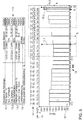
- step S6 the predicted time evolution of the range is output on the display area 2 of the user's mobile phone 10.
- a bar graph 12 having an x-axis and a y-axis is generated.
- the range R in kilometers is plotted on the y-axis and the determined duration t in hours on the x-axis.
- the x-axis is thereby subdivided in particular in times. In this case, there is a period of one hour between two times plotted next to one another. The temporal resolution of the x-axis is thus one hour.
- a bar 12.1 is plotted in the bar chart 12.
- Each of the bars 12.1 has a certain length L. The length L of each bar 12.1 corresponds to the range R predicted for the corresponding hour.
- a symbol 14 for the weather forecast is also displayed for each hour. Above the symbols 14, the expected outside temperature is also displayed. Between the bar graph 12 and the weather forecasting symbols 14, a value for the state of charge 16 is output. With decreasing outside temperature, the energy that needs to be expended for the air conditioning of the vehicle 7 when driving again, must be increased. This is then not ready for the implementation within range R ready. As the outside temperature drops, so does the predicted value for the range R.
- a list display 13 is displayed on the display surface 2.
- parameters relevant to the range projection are displayed.
- the top three columns 13.1 display information about the last trip performed. It will in particular the location of the vehicle 7, a time t 1 of the end of the journey and the state of charge displayed at the end of the journey.
- the time t 1 is composed in particular of time and date.
- next journey start can be determined via a history of vehicle usage.
- a state of charge can be specified, which the traction battery 5 should have at the beginning of the next trip.
- Column 13.3 displays loading information.
- the user can either load the vehicle 7 or not. If the user connects the vehicle 7 to a charging station, for example a power outlet, he is informed about the display a target time t 3 , which represents the beginning of the actual charging process, and a target state of charge, the traction battery 5 at the beginning of the next trip should show. If the user does not enter a desired time t 3 at which the charging process should begin, the latter is determined in such a way that the set value for the desired state of charge is reached at the next start of the journey. The user can also set the desired state of charge himself.
- a charging station for example a power outlet
- the user is automatically the type of charge over which the vehicle 7 is charged, so for example via a standard household power outlet or a charging station displayed.
- the maximum charging current is also determined and output. If the vehicle 7 is not charged during sleep mode, the user will not be presented with a time and date for the next charge start. The information about the charging mode and the maximum current will not be displayed.
- the last two columns provide information on pre-air conditioning.
- the user can basically set whether the pre-air conditioning should be activated during the rest phase of the vehicle 7 or not. If the pre-air conditioning is activated and, at the same time, the vehicle 7 is being charged, the energy required for the pre-air conditioning is obtained from the charging device. The energy required for this does not depend on the amount of energy in the traction battery 5.
- the user can set how long to pre-air-conditioned. As a rule, a period of 15 minutes is sufficient to heat or cool down a vehicle 7 to the desired interior temperature at the start of the journey.
- graphical elements 15.1 to 15.3 are displayed at certain times t 2 to t 4 .
- the position of the graphic elements 15.1 to 15.3 in the bar graph 12 is dependent on the times t 2 to t 4 .
- Graphic elements 15.1 to 15.3 have the shape of a rod with a final knob on. In this case, each graphical element 15.1 to 15.3 have a different color.
- the columns in the list representation 13, which relate to a respective graphical element 15.1 to 15.3, can be displayed in the same color. As a result, the assignment of the graphic elements 15.1 to 15.3 at one time is made easier for the user. If, for example, the graphic element 15.1 is displayed in green, the columns 13.3 of the list representation 13 are highlighted in green.
- the graphic element 15.2 is displayed in blue, the associated columns 13.4 are likewise highlighted in blue. If the graphic element 15.3 is displayed in yellow, the columns 13.2 are highlighted in yellow. By means of this color pattern, the user is shown in a simple manner which graphical element 15.1 to 15.3 belongs to which time t 2 to t 4 .
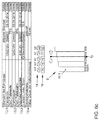
- Sections A and B from bar graph 12 of FIG. 5 are in the FIGS. 6a to 6c to explain how the different times t 2 to t 4 can be set, described in more detail.
- the user wishes to set the time t 2 , he can either do so directly via the corresponding column which corresponds to the upper column of the columns 13. 2 in the list representation 13. For this he touches the display area 2 at the column on the "Set” button. This opens a window in which the user can set the desired time.
- the user can also move the graphic element 15.3, which is assigned to the time t 2 , directly to the desired time by touching in the bar graph 12. This is in FIG. 6a shown. Since, however, then lies the time for a pre-air-conditioning after the start of the journey, the graphic element 15.2 can be coupled to the movement of the graphic element 15.3. The graphic element 15.2 is then shifted to the same extent as the graphic element 15.3. In this case, the distance D between the graphic elements 15.2 and 15.3 is maintained.
- the distance D can be changed by shifting the graphic element 15.2.
- the duration for the pre-air conditioning can also be set via the lower column of the columns 13.4. This is in FIG. 6b shown.
- FIG. 6c is an example of setting the target time t 3 shown.
- either the graphical element 15. 1 can be actively shifted by the user in the bar chart 12 or, alternatively, the time t 3 can be set via the corresponding column in the list display 13.
- the display in the list display 13 is automatically adapted accordingly. If one of the times t 2 to t 4 is set via the display in the list display 13, the position of the corresponding graphic element 15.1 to 15.3 is correspondingly adapted to the entry.
- the temporal development is re-predicted.
- the temporal evolution of the weather can also be constantly checked. If the weather forecast changes within the specified duration t, the forecast of the time evolution of the range R must also be adjusted.
- the reach forecast can be generated automatically. Automatic generation uses default settings for the forecast. For example, the user can store preferred settings for the times t 2 to t 4 in the vehicle 7. Alternatively, all settings can also be determined via a driving history.
- the range forecast can also be created manually by the user.
- the user as explained in the process, all times t 2 to t 4 , a desired state of charge of the vehicle battery 5 and a pre-air conditioning itself.
- the range forecast can also be semi-automatic. Some settings are taken from list view 13 and some are set manually by the user. For example, a desired state of charge can always be specified. In this case, the state of charge for the traction battery 5, which is distinguished by the manufacturer as optimal, is then stored in the list representation 13.
- a representation of the entire range that is to say the sum of the predicted electrical range and the conventional range, may alternatively also be represented, with no prognosis being made for the conventional range.
- the user is then advantageously not only displayed a part of the achievable range, but the entire achievable range of the vehicle 7.
- the electrical range visually displayed lifted from the conventional range so that the user can still read the pure electric range from the combined display.
Abstract
Die Erfindung betrifft ein Verfahren zum Prognostizieren einer Reichweite (R) eines Fahrzeugs (7) mit zumindest teilweise elektrischem Antrieb. Bei dem erfindungsgemäßen Verfahren wird erfasst, wenn zu einem Zeitpunkt (t 1 ) ein erster Betriebsmodus des Fahrzeugs (7) beendet wird, wobei das Fahrzeug (7) bei Beendigung des ersten Betriebsmodus in einen zweiten Betriebsmodus wechselt. Die Reichweite (R) des Fahrzeugs (7) bei Beendigung des ersten Betriebsmodus wird ermittelt. Ab dem Zeitpunkt (t 1 ) der Beendigung des ersten Betriebsmodus die zeitliche Entwicklung eines Parameters aus der Umgebung des Fahrzeugs (7) für eine bestimmte Dauer (t) ermittelt wird, wobei sich das Fahrzeug (7) während der bestimmten Dauer (t) zumindest teilweise in dem zweiten Betriebsmodus befindet. Weiterhin wird in Abhängigkeit von der Reichweite (R) bei Beendigung des ersten Betriebsmodus und der zeitlichen Entwicklung des Parameters die zeitliche Entwicklung der Reichweite (R) für die bestimmte Dauer (t) prognostiziert. Die zeitliche Entwicklung der Reichweite (R) wird ausgegeben. Ferner betrifft die Erfindung eine Vorrichtung (1) zum Prognostizieren einer Reichweite (R) eines Fahrzeugs (7) mit zumindest teilweise elektrischem Antrieb.The invention relates to a method for predicting a range (R) of a vehicle (7) with at least partially electric drive. In the method according to the invention is detected when at a time (t 1), a first operating mode of the vehicle (7) is terminated, wherein the vehicle (7) at the end of the first operating mode changes to a second operating mode. The range (R) of the vehicle (7) at the end of the first operating mode is determined. From the time (t 1) of the termination of the first operating mode, the time development of a parameter from the environment of the vehicle (7) for a certain duration (t) is determined, wherein the vehicle (7) during the determined duration (t) at least partially in the second operating mode. Furthermore, depending on the range (R) at the end of the first operating mode and the temporal development of the parameter, the time evolution of the range (R) for the specific duration (t) is predicted. The time evolution of the range (R) is output. Furthermore, the invention relates to a device (1) for predicting a range (R) of a vehicle (7) with at least partially electric drive.
Description
Die vorliegende Erfindung betrifft ein Verfahren und eine Vorrichtung zum Prognostizieren einer Reichweite eines Fahrzeugs mit zumindest teilweise elektrischem Antrieb.The present invention relates to a method and a device for predicting a range of a vehicle with at least partially electric drive.
Elektrisch angetriebene Fahrzeuge, z.B. Personenkraftwagen oder Lastkraftwagen, umfassen üblicherweise ein Speicherelement zum Speichern elektrischer Energie, wie beispielsweise einen wieder aufladbaren Akkumulator. Da sich beim Bremsen die überschüssige kinetische Energie des Fahrzeugs je nach Situation teilweise in elektrische Energie zurückgewinnen lässt, die dann unmittelbar für einen darauffolgenden Beschleunigungsvorgang wieder zur Verfügung steht, kann der Energieverbrauch und die Reichweite durch die Fahrweise und die Art der Energierückgewinnung beeinflusst werden.Electrically powered vehicles, e.g. Passenger cars or trucks usually include a storage element for storing electrical energy, such as a rechargeable battery. Depending on the situation, as the surplus kinetic energy of the vehicle during braking can be partially recovered into electrical energy, which is then immediately available for a subsequent acceleration process, the energy consumption and the range can be influenced by the driving style and the type of energy recovery.
Es ist allgemein wünschenswert, dem Fahrer bei Fahrtantritt und während der Fahrt Informationen über die Betriebsmittelvorräte des Fahrzeugs bereitzustellen und derart anzuzeigen, dass er sie intuitiv erfassen kann. Insbesondere ist es in der Frühphase der Elektromobilität wünschenswert, dem Fahrer sehr präzise Informationen über die zu erwartende Reichweite seines Fahrzeugs bereitzustellen. Zum einen liegen die Reichweiten solcher Fahrzeuge derzeit noch deutlich unterhalb der Reichweiten von Fahrzeugen mit Verbrennungsmotor. Andererseits ist die derzeit noch wenig flächendeckende Versorgung mit entsprechenden Ladestationen für die Fahrzeugbatterie bei Fahrtantritt zu bedenken, so dass die Reichweite eines Elektrofahrzeugs und Parameter, die Einfluss auf die Reichweite haben, für den Fahrer wichtige Informationen darstellen, die im Fahrzeug angezeigt werden sollten.It is generally desirable to provide the driver with on-board and on-the-run information about the resource stock of the vehicle and display it so that it can intuitively detect it. In particular, in the early phase of electromobility, it is desirable to provide the driver with very precise information about the expected range of his vehicle. On the one hand, the ranges of such vehicles are currently still well below the ranges of vehicles with internal combustion engines. On the other hand, the currently little nationwide supply of appropriate charging stations for the vehicle battery when driving is considered, so that the range of an electric vehicle and parameters that affect the range, the driver important information that should be displayed in the vehicle.
Aus der
Aus der
Aus der
Aus der
Der vorliegenden Erfindung liegt die Aufgabe zugrunde, ein Verfahren und ein Vorrichtung bereitzustellen, mittels welcher zu jedem Zeitpunkt eine zuverlässige Reichweitenbestimmung eines Fahrzeugs bereitgestellt werden kann.The object of the present invention is to provide a method and a device by means of which reliable range determination of a vehicle can be provided at any time.
Diese Aufgabe wird erfindungsgemäß durch ein Verfahren mit den Merkmalen des Anspruchs 1 und einer Vorrichtung mit den Merkmalen des Anspruchs 14 gelöst. Vorteilhafte Aus- und Weiterbildungen ergeben sich aus den abhängigen Ansprüchen.This object is achieved by a method having the features of
Bei dem erfindungsgemäßen Verfahren wird erfasst, wenn zu einem Zeitpunkt ein erster Betriebsmodus des Fahrzeugs beendet wird, wobei das Fahrzeug bei Beendigung des ersten Betriebsmodus in einen zweiten Betriebsmodus wechselt. Die Reichweite des Fahrzeugs bei Beendigung des ersten Betriebsmodus wird ermittelt. Es wird ab dem Zeitpunkt der Beendigung des ersten Betriebsmodus die zeitliche Entwicklung eines Parameters aus der Umgebung des Fahrzeugs für eine bestimmte Dauer ermittelt, wobei sich das Fahrzeug während der bestimmten Dauer zumindest teilweise in dem zweiten Betriebsmodus befindet. In Abhängigkeit von der Reichweite bei Beendigung des ersten Betriebsmodus und der zeitlichen Entwicklung des Parameters wird die zeitliche Entwicklung der Reichweite für die bestimmte Dauer prognostiziert. Die zeitliche Entwicklung der Reichweite wird ausgegeben. Insbesondere befindet sich das Fahrzeug im ersten Betriebsmodus in einem Fahrmodus und im zweiten Betriebsmodus in einem Ruhemodus. Insbesondere wird unter dem ersten Betriebsmodus ein Modus verstanden, in welchem der Motor des Fahrzeugs eingeschaltet ist. Der zweite Betriebsmodus ist ein Modus, in welchem der Motor des Fahrzeugs ausgeschaltet ist.In the method according to the invention, it is detected when a first operating mode of the vehicle is terminated at a time, wherein the vehicle changes to a second operating mode when the first operating mode ends. The range of the vehicle at the end of the first operating mode is determined. It is determined from the time of completion of the first mode of operation, the development over time of a parameter from the environment of the vehicle for a certain duration, wherein the vehicle is at least partially in the second operating mode during the determined duration. Depending on the range at the end of the first operating mode and the time evolution of the parameter the temporal evolution of the range is predicted for the given duration. The temporal evolution of the range is spent. In particular, the vehicle is in a drive mode in the first operating mode and in a sleep mode in the second operating mode. In particular, the first operating mode is understood as a mode in which the engine of the vehicle is switched on. The second operating mode is a mode in which the engine of the vehicle is turned off.
Durch das erfindungsgemäße Verfahren wird dem Nutzer vorteilhafterweise eine Reichweitenprognose auch während einer Ruhephase des Fahrzeugs, insbesondere einer Standphase, ausgegeben. In der Regel wird die Reichweite eines Fahrzeugs lediglich für die Dauer der Fahrt prognostiziert. Am Ende der Fahrt wird dann eine Restreichweite des Fahrzeugs ausgegeben, wie sie zu den zu dem Zeitpunkt des Fahrtendes vorliegenden Bedingungen erreichbar ist. Die Reichweite eines Fahrzeugs ist von unterschiedlichen Parametern abhängig. Verändern sich diese während der Standphase des Fahrzeugs, so verändert sich auch die Reichweite des Fahrzeugs. Kehrt der Nutzer also nach einer gewissen Zeit wieder zum Fahrzeug zurück, findet er eine andere Reichweite vor als sie beim vorherigen Fahrtende prognostiziert wurde. Eine zuverlässige Planung für zukünftige Fahrten ist daher nicht möglich. Durch die Prognose der zeitlichen Entwicklung der Reichweite in Abhängigkeit von einem Parameter aus der Umgebung des Fahrzeugs kann der Nutzer die Reichweite, die er bei einem erneuten Fahrtantritt vorfindet, besser einschätzen und dadurch seine zukünftigen Fahrten besser planen.The inventive method advantageously provides the user with a range prognosis even during a rest phase of the vehicle, in particular a stance phase. As a rule, the range of a vehicle is only forecast for the duration of the journey. At the end of the journey, a remaining range of the vehicle is then output, as it can be reached by the conditions prevailing at the time of the end of the journey. The range of a vehicle depends on different parameters. If these change during the stance phase of the vehicle, the range of the vehicle also changes. If the user returns to the vehicle after a certain time, he finds a different range than was predicted at the previous end of the journey. Reliable planning for future journeys is therefore not possible. By predicting the time evolution of the range as a function of a parameter from the environment of the vehicle, the user can better estimate the range that he finds when starting to drive again and thereby better plan his future journeys.
In einer Ausgestaltung des Verfahrens wird ein weiterer Zeitpunkt ermittelt, zu dem voraussichtlich von dem zweiten Betriebsmodus in den ersten Betriebsmodus gewechselt wird, und der weitere Zeitpunkt wird ausgegeben. Dabei stellt der weitere Zeitpunkt den Zeitpunkt eines erneuten Fahrtbeginns dar. Dadurch kann der Nutzer bei einer Ausgabe der zeitlichen Entwicklung der Reichweite über einen längeren Zeitraum die prognostizierte Reichweite bei einem erneuten Fahrtantritt genauer einschätzen. Der Nutzer kann insbesondere den weiteren Zeitpunkt selbst einstellen. Alternativ kann der weitere Zeitpunkt aus einer Fahrhistorie des Fahrzeugs ermittelt werden. Dabei wird beispielsweise über einen längeren Zeitraum erfasst, zu welchen Uhrzeiten der Nutzer das Fahrzeug verwendet, und darüber wird der weitere Zeitpunkt geschätzt.In one embodiment of the method, a further point in time is determined at which it is likely to change from the second operating mode to the first operating mode, and the further time is output. In this case, the further point in time represents the time of a new start of the journey. As a result, the user can more accurately estimate the predicted range for a renewed journey when outputting the temporal development of the range over a longer period of time. In particular, the user can set the additional time himself. Alternatively, the additional time can be determined from a driving history of the vehicle. In this case, for example, it is detected over a longer period of time, at which times the user uses the vehicle, and about the further time is estimated.
Insbesondere umfasst der Parameter Wetterbedingungen in der Umgebung des Fahrzeugs. Als zeitliche Entwicklung wird eine Wetterprognose für die bestimmte Dauer ermittelt. Dabei kann die Wetterprognose automatisch über ein Netzwerk eingeholt und für die Prognose verwendet werden. Wetterbedingungen sind dabei von besonderem Interesse, denn insbesondere in Standphasen, in welchen das Fahrzeug in der Regel nicht eingeschaltet ist, üben diese den größten Einfluss auf die Reichweitenprognose während der Standphase aus. Insbesondere die Außentemperatur hat einen großen Einfluss auf die zeitliche Entwicklung der Reichweite. Die Energie, welche für die Klimatisierung des Fahrzeugs aufgewendet werden muss, ist insbesondere von der Außentemperatur abhängig. Die Energiemenge, die benötigt wird, um die Innentemperatur auf einen gewünschten Wert zu bringen, ist umso höher, je mehr die Außentemperatur und die gewünschte Innentemperatur voneinander abweichen.In particular, the parameter includes weather conditions in the vicinity of the vehicle. As temporal development, a weather forecast for the specific duration is determined. The weather forecast can be obtained automatically over a network and used for the forecast. Weather conditions are of particular interest because, especially in stance phases in which the vehicle is not usually switched on, they exert the greatest influence on the range prognosis during the stance phase. especially the Outside temperature has a big impact on the time evolution of the range. The energy which has to be expended for the air conditioning of the vehicle depends in particular on the outside temperature. The amount of energy needed to bring the internal temperature to a desired value is the higher the more the outside temperature and the desired inside temperature differ.
Insbesondere wird die Position des Fahrzeugs ermittelt und die Wetterprognose für die Position des Fahrzeugs ermittelt. Dadurch kann die Prognose der Reichweite verbessert werden. Die Wahrscheinlichkeit, dass Wetterschwankungen, die sich auch innerhalb weniger Kilometer ergeben können, die Prognose beeinflussen, kann dadurch verringert werden. Die Position des Fahrzeugs kann dabei insbesondere über Satellitennavigation, wie z. B. GPS, ermittelt werden.In particular, the position of the vehicle is determined and the weather forecast for the position of the vehicle is determined. This can improve the forecast of the range. The probability that weather fluctuations, which can also occur within a few kilometers, influence the forecast, can be reduced thereby. The position of the vehicle can in particular satellite navigation, such. B. GPS, are determined.
In einer weiteren Ausgestaltung wird ermittelt, ob ein Energiespeicher des Fahrzeugs während des zweiten Betriebsmodus aufgeladen wird. Wenn der Energiespeicher aufgeladen wird, wird die zeitliche Entwicklung des Ladezustands des Energiespeichers prognostiziert und in der Prognose der zeitlichen Entwicklung der Reichweite berücksichtigt. Wird beispielsweise das Fahrzeug während des zweiten Betriebsmodus aufgeladen, hat dies einen großen Einfluss auf die Reichweite des Fahrzeugs bei einem erneuten Fahrtbeginn. Dies muss daher bei der Prognose der zeitlichen Entwicklung berücksichtigt werden.In a further embodiment, it is determined whether an energy storage of the vehicle is charged during the second operating mode. When the energy storage is charged, the temporal evolution of the state of charge of the energy storage is predicted and taken into account in the forecast of the development over time of the range. If, for example, the vehicle is charged during the second operating mode, this has a great influence on the range of the vehicle when the vehicle starts to drive again. This must therefore be taken into account in the prognosis of the temporal development.
In einer anderen Ausgestaltung wird eine Soll-Energiemenge ermittelt, welche der Energiespeicher des Fahrzeugs zu dem weiteren Zeitpunkt aufweisen soll. Es wird ein Soll-Zeitpunkt ermittelt, zu welchem ein Ladevorgang zum Laden des Energiespeichers gestartet werden muss, um die Soll-Energiemenge zu dem weiteren Zeitpunkt bereitzustellen. Der Soll-Zeitpunkt wird ausgegeben. Dadurch kann der Nutzer vorteilhafterweise selbst bestimmen, welchen Ladezustand der Energiespeicher bei einem erneuten Fahrtbeginn aufweisen soll. Insbesondere kann eine vollständige Ladung einer Fahrzeugbatterie aus Kostengründen nicht erwünscht sein. Um dann zum Zeitpunkt des erneuten Fahrtbeginns den gewünschten Ladezustand der Batterie vorweisen zu können, wird ein Soll-Zeitpunkt berechnet, zu welchem der Ladevorgang gestartet werden muss, um die gewünschte Soll-Energiemenge bei einem erneuten Fahrtbeginn bereitstellen zu können.In another embodiment, a desired amount of energy is determined, which should have the energy storage of the vehicle at the further time. A target point in time is determined at which a charging process for charging the energy store has to be started in order to provide the desired amount of energy at the further time. The target time is output. As a result, the user can advantageously determine for himself which charge state the energy store should have when the journey starts again. In particular, a full charge of a vehicle battery may not be desirable for reasons of cost. In order then to be able to present the desired state of charge of the battery at the time of the re-start of travel, a desired point in time is calculated at which the charging process must be started in order to be able to provide the desired set amount of energy when the journey starts again.
In einer weiteren Ausgestaltung ist die zeitliche Auflösung der bestimmten Dauer abhängig von der zeitlichen Auflösung des Parameters. Die zeitliche Auflösung einer Wetterprognose ist in der Regel beschränkt und liegt bei einer bis mehreren Stunden oder Tage. Dies bedeutet, dass jeder Zeitpunkt innerhalb der zeitlichen Entwicklung des Parameters ebenfalls eine bestimmte Dauer aufweist.In a further embodiment, the temporal resolution of the specific duration is dependent on the temporal resolution of the parameter. The temporal resolution of a weather forecast is usually limited and is one to several hours or days. This means that each time within the temporal evolution of the parameter also has a certain duration.
Weiterhin kann auf einer Anzeigefläche eine graphische Darstellung erzeugt werden, mittels welcher die zeitliche Entwicklung der Reichweite ausgegeben wird. Insbesondere umfasst die graphische Darstellung ein Diagramm, bevorzugt ein Balkendiagramm, wobei auf einer ersten Achse die bestimmte Dauer und auf einer zweiten Achse die prognostizierte Reichweite aufgetragen ist. Dabei wird die prognostizierte Reichweite mittels des Diagramms, insbesondere mittels einer Länge der Balken des Balkendiagramms, ausgegeben. Dies stellt vorteilhafterweise ein besonders intuitive und einfache Darstellungsweise der Reichweite dar. Insbesondere ergibt sich durch die Balkendarstellung eine eingängige Darstellungsart der Reichweite, bei der die Längen der Balken eine einfach zu verstehende Anzeige für die prognostizierte Reichweite zu jedem Zeitpunkt während der prognostizierten zeitlichen Entwicklung darstellt.Furthermore, a graphical representation can be generated on a display surface, by means of which the temporal evolution of the range is output. In particular, the graphical representation comprises a diagram, preferably a bar chart, wherein the determined duration is plotted on a first axis and the predicted range on a second axis. The predicted range is output by means of the diagram, in particular by means of a length of the bars of the bar chart. This advantageously represents a particularly intuitive and simple representation of the range. In particular, the bar presentation provides a catchy representation of the range, in which the lengths of the bars represent an easy-to-understand display for the forecast range at any time during the predicted time evolution.
Beispielsweise weist die zeitliche Auflösung des Parameters die Einheit Stunden auf. Die bestimmte Dauer umfasst beispielsweise 24 Stunden und auf der ersten Achse werden Uhrzeiten mit einem Abstand von jeweils einer Stunde zwischen zwei aufeinanderfolgenden Uhrzeiten aufgetragen. Eine stündliche Auflösung ist ausreichend, um eine zufriedenstellende Auflösung der zeitlichen Entwicklung der Reichweite bereitstellen zu können. Zudem wird eine Wetterprognose in der Regel nicht besser zeitlich aufgelöst getroffen.For example, the temporal resolution of the parameter has the unit hours. For example, the determined duration comprises 24 hours, and on the first axis, times are plotted at intervals of one hour between two consecutive times. An hourly resolution is sufficient to provide a satisfactory resolution of the temporal evolution of the range. In addition, a weather forecast is generally not better resolved temporally resolved.
Weiterhin kann das graphische Diagramm für jeden ausgegebenen Zeitpunkt ein graphisches Element aufweisen. Dabei sind die ausgegebenen Zeitpunkte insbesondere der weitere Zeitpunkt und der Soll-Zeitpunkt. Der erste Zeitpunkt wird indirekt über die erste Uhrzeit auf der ersten Achse des Diagramms ausgegeben. Dadurch wird dem Nutzer vorteilhafterweise in der graphischen Darstellung verdeutlicht, wann ein Ladevorgang beginnt und wann ein nächster Fahrtbeginn geplant ist.Furthermore, the graphical diagram may have a graphical element for each output time. In this case, the output times are in particular the further time and the desired time. The first time is output indirectly over the first time on the first axis of the chart. As a result, the user is advantageously made clear in the graphical representation when a loading process begins and when a next start of the journey is planned.
Zudem kann ein Zeitpunkt ermittelt werden, zu dem eine Vorklimatisierung gestartet werden soll. Eine Vorklimatisierung wird in der Regel für ca. 15 Minuten vor Fahrtbeginn eingestellt. Nach 15 Minuten Vorklimatisierung findet der Nutzer in der Regel die von ihm gewünschten Klimabedingungen im Fahrzeug vor. Die Vorklimatisierung kann beispielsweise immer 15 Minuten vor geplanten Fahrtbeginn aktiviert werden. Alternativ kann der Nutzer den Zeitpunkt, zu welchem eine Vorklimatisierung gestartet werden soll, selbst eingeben. Dazu kann ebenso ein graphisches Element für den Zeitpunkt der Vorklimatisierung auf der Anzeigefläche angezeigt werden.In addition, a time can be determined at which a pre-air conditioning is to be started. A pre-air conditioning is usually set for about 15 minutes before the start of the journey. After 15 minutes of pre-air conditioning, the user usually finds the desired climate conditions in the vehicle. For example, the pre-air conditioning can always be activated 15 minutes before the planned start of the journey. Alternatively, the user can himself enter the time at which a pre-air conditioning is to be started. For this purpose, a graphic element for the time of Vorklimatisierung can also be displayed on the display surface.
In einer weiteren Ausgestaltung ist zumindest eines der graphischen Elemente in dem Diagramm entlang der ersten Achse verschiebbar, so dass der Zeitpunkt mittels Verschieben des graphischen Elements einstellbar ist. Der Nutzer kann dadurch vorteilhafterweise auf einfache und intuitive Weise den gewünschten Zeitpunkt manuell einstellen.In a further embodiment, at least one of the graphical elements in the diagram is displaceable along the first axis, so that the time is adjustable by moving the graphic element. The user can thereby advantageously set the desired time manually in a simple and intuitive way.
Insbesondere ist die Anzeigefläche, auf welcher die zeitliche Entwicklung der Reichweite ausgegeben wird, nicht in dem Fahrzeug selbst angeordnet. Beispielsweise wird die zeitliche Entwicklung über eine Anzeigefläche eines Mobiltelefons, Tablet-Computers, PCs oder sonstigen Geräten mit Anzeigeflächen ausgegeben. Dadurch muss der Nutzer zum Einstellen der Zeitpunkte oder zum Ausgeben der zeitlichen Entwicklung der Reichweite nicht zum Fahrzeug zurückkehren, um Einstellungen zu ändern bzw. sich die zeitliche Entwicklung der Reichweite anzusehen.In particular, the display area on which the temporal evolution of the range is output is not arranged in the vehicle itself. For example, the development over time is output via a display area of a mobile phone, tablet computer, PC or other devices with display areas. As a result, the user does not have to return to the vehicle to set the times or spend the time evolution of the range to change settings or to look at the time evolution of the range.
Ferner betrifft die Erfindung eine Vorrichtung zum Prognostizieren einer Reichweite eines Fahrzeugs mit zumindest teilweise elektrischem Antrieb. Die Vorrichtung umfasst eine Erfassungseinheit, mittels welcher erfassbar ist, wenn zu einem Zeitpunkt ein erster Betriebsmodus des Fahrzeugs beendet wird, wobei das Fahrzeug bei Beendigung des ersten Betriebsmodus in einen zweiten Betriebsmodus wechselt. Weiterhin umfasst die Vorrichtung eine Ermittlungseinheit, mittels welcher die Reichweite des Fahrzeugs bei Beendigung des ersten Betriebsmodus und ab dem Zeitpunkt der Beendigung des ersten Betriebsmodus die zeitliche Entwicklung eines Parameters aus der Umgebung des Fahrzeugs für eine bestimmte Dauer ermittelbar ist. Zudem umfasst die Vorrichtung eine Prognoseeinheit, mittels welcher in Abhängigkeit von der Reichweite bei Beendigung des ersten Betriebsmodus und der zeitlichen Entwicklung des Parameters die zeitliche Entwicklung der Reichweite für die bestimmte Dauer prognostizierbar ist. Mittels einer Ausgabeeinheit ist die prognostizierte zeitliche Entwicklung der Reichweite ausgebbar. Die erfindungsgemäße Vorrichtung ist insbesondere zum Ausführen des erfindungsgemäßen Verfahrens geeignet und weist daher alle Vorteile des erfindungsgemäßen Verfahrens auf.Furthermore, the invention relates to a device for predicting a range of a vehicle with at least partially electric drive. The device comprises a detection unit, by means of which it can be detected when a first operating mode of the vehicle is terminated at a time, wherein the vehicle changes at the end of the first operating mode in a second operating mode. Furthermore, the device comprises a determination unit, by means of which the range of the vehicle at the end of the first operating mode and from the time of termination of the first operating mode, the temporal evolution of a parameter from the environment of the vehicle for a certain duration can be determined. In addition, the device comprises a prediction unit, by means of which, depending on the range at the end of the first operating mode and the temporal development of the parameter, the time evolution of the range for the specific duration can be predicted. By means of an output unit, the predicted temporal evolution of the range can be output. The device according to the invention is particularly suitable for carrying out the method according to the invention and therefore has all the advantages of the method according to the invention.
Ferner betrifft die Erfindung ein Fahrzeug mit einer solchen Vorrichtung. Bei dem Fahrzeug handelt es sich insbesondere um ein Fahrzeug mit vollständigem elektrischem Antrieb, beispielsweise um ein Elektrofahrzeug, oder um ein Fahrzeug mit teilweise elektrischem Antrieb, also beispielsweise um ein Hybridfahrzeug. Bei einem Hybridfahrzeug setzt sich die gesamte Reichweite des Fahrzeugs aus der elektrischen Reichweite, also der Reichweite die mit der in der Traktionsbatterie des Fahrzeugs vorhandenen Energiemenge erreicht werden kann, und und der herkömmlichen Reichweite zusammen, also der Reichweite, die durch die in einem herkömmlichen Tank vorhandenen Brennstoffmenge, die einem Verbrennungsmotor zur Verfügung steht, erreicht werden kann. Wird ein Hybridfahrzeug betrieben, wird das Fahrzeug zunächst mit elektrischer Energie aus der Traktionsbatterie angetrieben. Ein Verbrennungsmotor wird erst dann verwendet, wenn die Energie aus der Traktionsbatterie nicht mehr zum Antrieb des Fahrzeugs ausreicht. Bei einem Hybridfahrzeug ist für den Nutzer insbesondere die elektrische Reichweite von Interesse. Durch das erfindungsgemäße Verfahren wird daher bei einem Hybridfahrzeug insbesondere die elektrische Reichweite prognostiziert und dem Nutzer ausgegeben.Furthermore, the invention relates to a vehicle with such a device. The vehicle is in particular a vehicle with a complete electric drive, for example an electric vehicle, or a vehicle with a partially electric drive, that is, for example, a hybrid vehicle. In a hybrid vehicle, the total range of the vehicle is composed of the electrical range, that is, the range that can be achieved with the amount of energy present in the traction battery of the vehicle, and the conventional range, that is, range, that in a conventional tank existing amount of fuel that is available to an internal combustion engine, can be achieved. When a hybrid vehicle is operated, the vehicle is first powered by electrical energy from the traction battery. An internal combustion engine is only used when the energy from the traction battery is no longer sufficient to drive the vehicle. In a hybrid vehicle, the user is particularly interested in the electrical range. The inventive method is therefore at a Hybrid vehicle in particular predicts the electric range and issued to the user.
Die Erfindung wird nun anhand von Ausführungsbeispielen mit Bezug zu den beigefügten Zeichnungen erläutert.
- Fig. 1
- zeigt ein erstes Ausführungsbeispiel der erfindungsgemäßen Vorrichtung,
- Fig. 2
- zeigt ein Anordnungsbeispiel des ersten Ausführungsbeispiels der erfindungsgemäßen Vorrichtung in einem Fahrzeug,
- Fig. 3
- zeigt ein zweites Ausführungsbeispiel der erfindungsgemäßen Vorrichtung,
- Fig. 4
- zeigt ein Flussdiagramm eines Ausführungsbeispiels des erfindungsgemäßen Verfahrens,
- Fig. 5
- zeigt eine Anzeige, wie sie von dem erfindungsgemäßen Verfahren auf einer Anzeigefläche erzeugbar ist, und
- Fig. 6a bis 6c
- zeigen Ausführungsbeispiele zum Einstellen verschiedener Zeitpunkte für das erfindungsgemäße Verfahren.
- Fig. 1
- shows a first embodiment of the device according to the invention,
- Fig. 2
- shows an arrangement example of the first embodiment of the device according to the invention in a vehicle,
- Fig. 3
- shows a second embodiment of the device according to the invention,
- Fig. 4
- shows a flow chart of an embodiment of the method according to the invention,
- Fig. 5
- shows an indication as it can be generated by the method according to the invention on a display surface, and
- Fig. 6a to 6c
- show exemplary embodiments for setting different times for the method according to the invention.
Mit Bezug zu den
Die Vorrichtung 1 umfasst zunächst eine Erfassungseinheit 8, mittels welcher erfassbar ist, wenn das Fahrzeug 7 von einem ersten Betriebsmodus in einen zweiten Betriebsmodus wechselt.The
Der erste Betriebsmodus ist dabei insbesondere ein Fahrmodus. Insbesondere wird unter dem ersten Betriebsmodus ein Modus verstanden, in welchem der Motor des Fahrzeugs 7 eingeschaltet ist. Der zweite Betriebsmodus ist insbesondere ein Ruhemodus des Fahrzeugs 7. Insbesondere ist der zweite Betriebsmodus ein Modus, in welchem der Motor des Fahrzeugs 7 ausgeschaltet ist. Die Erfassungseinheit 8 erfasst somit, wenn der Motor des Fahrzeugs 7 ausgeschaltet wird.The first operating mode is in particular a driving mode. In particular, the first operating mode is understood to mean a mode in which the engine of the
Zudem umfasst die Vorrichtung 1 eine Ermittlungseinheit 4. Die Ermittlungseinheit 4 ist dabei zur Ermittlung unterschiedlicher Parameter ausgestaltet. Zunächst ermittelt die Ermittlungseinheit 4, welche Reichweite das Fahrzeug 7 bei Beendigung des Fahrmodus aufweist. Dazu ermittelt die Ermittlungseinheit 4 insbesondere den Ladezustand eines Energiespeichers 5, beispielsweise einer Traktionsbatterie, zum Zeitpunkt der Beendigung des Fahrmodus und berechnet daraus die Reichweite.In addition, the
Zudem ermittelt die Ermittlungseinheit 4, beispielsweise über ein Netzwerk 6, die zeitliche Entwicklung des Wetters in der Umgebung des Fahrzeugs 7. Das Wetter entspricht dabei einem Parameter, der einen Einfluss auf die Reichweitenprognose während einer Ruhephase des Fahrzeugs 7 hat.In addition, the
Die von der Ermittlungseinheit 4 ermittelten Parameter werden an eine Prognoseeinheit 3 übermittelt. In der Prognoseeinheit 3 wird dann die zeitliche Entwicklung der Reichweite aus den entsprechenden Parametern prognostiziert.The parameters determined by the
Die prognostizierte zeitliche Entwicklung der Reichweite wird an eine Steuervorrichtung 9, welche in einem Mobiltelefon 10 des Nutzers angeordnet ist, übermittelt. Die Steuervorrichtung 9 erzeugt dann auf der Anzeigefläche 2 des Mobiltelefons 10 des Nutzers eine graphische Darstellung zur Visualisierung der zeitlichen Entwicklung der Reichweite.The predicted time evolution of the range is transmitted to a
Im ersten Ausführungsbeispiel der erfindungsgemäßen Vorrichtung 1, ist die Mehrzahl der Vorrichtungskomponenten in dem Fahrzeug 7 selbst angeordnet.In the first embodiment of the
Bei dem in
Insbesondere verfügt das Mobiltelefon 10 des Nutzers über eine Anwendung, welche extra für die Reichweitenprognose entwickelt worden ist. Die Traktionsbatterie 5 und die Erfassungseinheit 8 sind weiterhin im Fahrzeug 7 angeordnet. Zudem weist die Vorrichtung 1 des zweiten Ausführungsbeispiels eine weitere Ermittlungseinheit 11 auf, welche mit der Ermittlungseinheit 4 gekoppelt ist, so dass die Ermittlungseinheit 4 mittels der Ermittlungseinheit 11 Informationen über die Reichweite und den Ladezustand der Traktionsbatterie 5 erhält.In particular, the user's
Auf der Anzeigefläche 2 des Mobiltelefons 10 kann insbesondere eine berührungsempfindliche Oberfläche angeordnet sein, mittels welcher der Nutzer Einstellungen für die Prognose der zeitlichen Entwicklung der Reichweite vornehmen kann.In particular, a touch-sensitive surface can be arranged on the
Bei dem Fahrzeug 7 kann es sich entweder um ein Elektrofahrzeug oder ein Hybridfahrzeug handeln. Beide Fahrzeugtypen weisen eine Traktionsbatterie 5 auf, aus welcher die Energie für den Antrieb des Fahrzeugs 7 gespeist wird. Bei einem Elektrofahrzeug wird dabei die Antriebsenergie nur aus der Traktionsbatterie 5 gespeist. Neigt sich die Energiemenge in der Traktionsbatterie 5 dem Ende zu, muss die Traktionsbatterie 5 wieder aufgeladen werden. Andernfalls ist ein Weiterbetrieb des Fahrzeug 7 nicht möglich.The
Bei einem Hybridfahrzeug hingegen wird, wenn die Traktionsbatterie 5 ausreichend geladen ist, die Energie aus der Traktionsbatterie 5 gespeist. Ist die Traktionsbatterie 5 nicht mehr ausreichend geladen, wird die Antriebsenergie aus einem herkömmlichen Kraftstoff, beispielsweise Benzin oder Diesel, gewonnen. Somit setzt sich die gesamte Reichweite eines Hybridfahrzeugs aus der elektrischen Reichweite und einer herkömmlichen Reichweite, die durch den Antrieb mittels eines herkömmlichen Kraftstoffs erreicht werden kann, zusammen. Bei einem Hybridfahrzeug wird das erfindungsgemäße Verfahren insbesondere für die elektrische Reichweite, welche mit der in der Traktionsbatterie 5 vorhandenen Energiemenge erreicht werden kann, ausgeführt. Dadurch kann der Nutzer eines Hybridfahrzeugs vorteilhafterweise besser einschätzen, wie weit er durch rein elektrischen Antrieb noch fahren kann. Im Folgenden ist mit der Bezeichnung Reichweite insbesondere die elektrische Reichweite gemeint.In contrast, in a hybrid vehicle, when the
Mit Bezug zu
Ausgangspunkt ist dabei, dass der Fahrer sein Fahrzeug 7 zum Parken, beispielsweise über Nacht, abstellt.The starting point is that the driver turns off his
Dabei schaltet der Fahrer zunächst den Motor des Fahrzeugs 7 ab. In Schritt S1 des Verfahrens wird zunächst erfasst, dass das Fahrzeug 7 von einem Fahrmodus in einen Parkmodus wechselt.In this case, the driver first shuts off the engine of the
In Schritt S2 wird die Reichweite, die mit dem momentanen Ladezustand unter den momentan vorherrschenden Wetterbedingungen erreichbar ist, ermittelt.In step S2, the range achievable with the current state of charge under the currently prevailing weather conditions is determined.
In Schritt S3 ermittelt die Ermittlungseinheit 4 die Position des Fahrzeugs 7. Dies geschieht beispielsweise über ein Navigationssystem mit integriertem GPS-Empfänger.In step S3, the
In Schritt S4 verbindet sich die Ermittlungseinheit 4 mit dem Netzwerk 6 und holt über das Netzwerk eine Wetterprognose für die nächsten 24 Stunden an der Position des Fahrzeugs 7 ein. Die Wetterprognose hat dabei eine zeitliche Auflösung mit der Einheit Stunden. Dies bedeutet, dass für jede der 24 Stunden, eine separate Wetterprognose vorliegt. Die Wetterprognose für die 24 Stunden entspricht dabei einer zeitlichen Entwicklung des Wetters innerhalb der nächsten 24 Stunden.In step S4, the
In Schritt S5 wird dann eine Prognose für die zeitliche Entwicklung der Reichweite innerhalb der nächsten 24 Stunden in Abhängigkeit von der zeitlichen Entwicklung der Wetterprognose erstellt.In step S5, a forecast for the time evolution of the range within the next 24 hours is then created as a function of the temporal evolution of the weather forecast.
In Schritt S6 wird die prognostizierte zeitliche Entwicklung der Reichweite auf der Anzeigefläche 2 des Mobiltelefons 10 des Nutzers ausgegeben.In step S6, the predicted time evolution of the range is output on the
Mit Bezug zu den
Es wird zunächst ein Balkendiagramm 12 mit einer x-Achse und einer y-Achse erzeugt. Dabei ist auf der y-Achse die Reichweite R in Kilometern und auf der x-Achse die bestimmte Dauer t in Stunden aufgetragen. Die x-Achse wird dabei insbesondere in Uhrzeiten untergliedert. Dabei liegt zwischen zwei nebeneinander aufgetragenen Uhrzeiten eine Zeitspanne von einer Stunde. Die zeitliche Auflösung der x-Achse beträgt also eine Stunde. Für jeden x-Achsenpunkt, also für jede Uhrzeit, ist in dem Balkendiagramm 12 ein Balken 12.1 aufgetragen. Jeder der Balken 12.1 weist eine gewisse Länge L auf. Die Länge L jedes Balkens 12.1 entspricht dabei der für die entsprechende Stunde prognostizierte Reichweite R.First, a
Oberhalb des Balkendiagramms 12 wird zudem für jede Stunde ein Symbol 14 für die Wetterprognose angezeigt. Oberhalb der Symbole 14 wird zudem die zu erwartende Außentemperatur angezeigt. Zwischen dem Balkendiagramm 12 und den Symbolen 14 für die Wetterprognose wird ein Wert für den Ladezustand 16 ausgegeben. Mit sinkender Außentemperatur muss die Energie, welche für die Klimatisierung des Fahrzeugs 7 bei einer erneuten Fahrt aufgewendet werden muss, erhöht werden. Diese steht dann nicht für die Umsetzung in Reichweite R bereit. Mit sinkender Außentemperatur sinkt daher auch der prognostizierte Wert für die Reichweite R.Above the
Zudem wird auf der Anzeigefläche 2 eine Listendarstellung 13 angezeigt. In der Listendarstellung 13 werden für die Reichweitenprognose relevante Parameter angezeigt. In den obersten drei Spalten 13.1 werden Information zur letzten durchgeführten Fahrt angezeigt. Es werden insbesondere der Standort des Fahrzeugs 7, ein Zeitpunkt t1 des Fahrtendes sowie der Ladezustand bei Fahrtende angezeigt. Der Zeitpunkt t1 setzt sich dabei insbesondere aus Uhrzeit und Datum zusammen.In addition, a
In den Spalten 13.2 werden Informationen zum nächsten Fahrtbeginn angegeben. Beispielsweise kann der Nutzer einen Zeitpunkt t2, zu welcher er voraussichtlich das Fahrzeug 7 wieder verwenden wird, einstellen. Alternativ kann ein nächster Fahrtbeginn über eine Historie zur Fahrzeugverwendung bestimmt werden. Zudem kann ein Ladezustand angegeben werden, den die Traktionsbatterie 5 zu Beginn der nächsten Fahrt aufweisen soll.In columns 13.2, information about the next start of the journey is given. For example, the user may set a time t 2 at which he is expected to reuse the
In den Spalten 13.3 werden Informationen zum Ladevorgang angezeigt. Bei Fahrtende kann der Nutzer das Fahrzeug 7 entweder laden oder nicht. Falls der Nutzer das Fahrzeug 7 an eine Ladestation, beispielsweise eine Steckdose anschließt, wird ihm über die Anzeige ein Soll-Zeitpunkt t3, welcher den Beginn des eigentlichen Ladevorgangs darstellt, und ein Soll-Ladezustand, den die Traktionsbatterie 5 zu Beginn der nächsten Fahrt aufweisen soll, angezeigt. Gibt der Nutzer keinen Soll-Zeitpunkt t3 ein, zu welchem der Ladevorgang beginnen soll, wird dieser so ermittelt, dass zum nächsten Fahrtbeginn der eingestellte Wert für den Soll-Ladezustand erreicht wird. Auch den Soll-Ladezustand kann der Nutzer selbst einstellen. Zudem wird dem Nutzer automatisch die Ladeart, über welche das Fahrzeug 7 aufgeladen wird, also beispielsweise über eine haushaltsübliche Steckdose oder über eine Ladestation, angezeigt. Auch der maximale Ladestrom wird ermittelt und ausgegeben. Wird das Fahrzeug 7 während des Ruhemodus nicht geladen, wird dem Nutzer keine Uhrzeit und kein Datum für den nächsten Ladebeginn angezeigt. Auch die Informationen zur Ladeart und zum maximalen Strom werden dann nicht angezeigt.Column 13.3 displays loading information. At the end of the journey, the user can either load the
In den letzten beiden Spalten werden Informationen zu einer Vorklimatisierung angegeben. Solange bestimmte Bedingungen erfüllt sind, kann der Nutzer grundsätzlich einstellen, ob die Vorklimatisierung während der Ruhephase des Fahrzeugs 7 aktiviert werden soll oder nicht. Ist die Vorklimatisierung aktiviert und wird gleichzeitig das Fahrzeug 7 geladen, wird die Energie, welche für die Vorklimatisierung benötigt wird, aus der Ladeeinrichtung bezogen. Die dafür benötigte Energie geht also nicht von der Energiemenge in der Traktionsbatterie 5 ab. Zudem kann der Nutzer einstellen, wie lange vorklimatisiert werden soll. In der Regel ist eine Dauer von 15 Minuten ausreichend, um ein Fahrzeug 7 auf die bei Fahrtantritt gewünschte Innentemperatur aufzuheizen oder herabzukühlen.The last two columns provide information on pre-air conditioning. As long as certain conditions are met, the user can basically set whether the pre-air conditioning should be activated during the rest phase of the
In dem Balkendiagramm 12 werden bei bestimmten Zeitpunkten t2 bis t4 graphische Elemente 15.1 bis 15.3 angezeigt. Die Position der graphischen Elemente 15.1 bis 15.3 in dem Balkendiagramm 12 ist dabei abhängig von den Zeitpunkten t2 bis t4. Die graphischen Elemente 15.1 bis 15.3 weisen dabei die Form eines Stabes mit abschließendem Knauf auf. Dabei kann jedes graphische Element 15.1 bis 15.3 eine andere Farbe aufweisen. Gleichzeitig können die Spalten in der Listendarstellung 13, welche ein jeweiliges graphisches Element 15.1 bis 15.3 betreffen, in der gleichen Farbe dargestellt werden. Dadurch wird dem Nutzer die Zuordnung der graphischen Elemente 15.1 bis 15.3 zu einem Zeitpunkt erleichtert. Wird also beispielsweise das graphische Element 15.1 grün dargestellt, werden die Spalten 13.3 der Listendarstellung 13 grün hinterlegt. Wird das graphische Element 15.2 blau dargestellt, werden die zugehörigen Spalten 13.4 ebenso blau hinterlegt. Wird das graphische Element 15.3 gelb dargestellt, werden die Spalten 13.2 gelb hinterlegt. Durch dieses Farbmuster wird dem Nutzer auf einfache Art und Weise dargelegt, welches graphische Element 15.1 bis 15.3 zu welchem Zeitpunkt t2 bis t4 gehört.In the
Die Abschnitte A und B aus dem Balkendiagramm 12 der
Möchte der Nutzer beispielsweise den Zeitpunkt t2 einstellen, kann er dies entweder direkt über die entsprechende Spalte, welche der oberen Spalte der Spalten 13.2 entspricht in der Listendarstellung 13 tun. Dazu berührt er die Anzeigefläche 2 bei der Spalte auf der Schaltfläche "Einstellen". Es öffnet sich dann ein Fenster, in welchem der Nutzer die gewünschte Uhrzeit einstellen kann. Alternativ kann der Nutzer auch das graphische Element 15.3, welches dem Zeitpunkt t2 zugeordnet ist, direkt über Berühren in dem Balkendiagramm 12 auf die gewünschte Uhrzeit verschieben. Dies ist in
Der Abstand D kann dadurch verändert werden, dass das graphische Element 15.2 verschoben wird. Alternativ kann auch über die untere Spalte der Spalten 13.4 die Dauer für die Vorklimatisierung eingestellt werden. Dies ist in
In
Wird einer der Zeitpunkte t2 bis t4 über das entsprechende graphische Element 15.1 bis 15.3 eingestellt, wird die Anzeige in der Listendarstellung 13 automatisch entsprechend angepasst. Wird einer der Zeitpunkte t2 bis t4 über die Anzeige in der Listendarstellung 13 eingestellt, wird entsprechend die Position des entsprechenden graphischen Elements 15.1 bis 15.3 an den Eintrag angepasst.If one of the times t 2 to t 4 is set via the corresponding graphical element 15.1 to 15.3, the display in the
Wird einer der Zeitpunkte t2 bis t4 vom Nutzer angepasst, insbesondere der Soll-Zeitpunkt t3 und/oder der Zeitpunkt t4, an welchem eine Vorklimatisierung starten soll, wird die zeitliche Entwicklung neu prognostiziert.If one of the time points t 2 to t 4 adjusted by the user, in particular the desired point in time t 3 and / or the time t 4, at which to start a preconditioning, the temporal development is re-predicted.
Wird hingegen lediglich der Zeitpunkt t2 geändert, und wird das Fahrzeug 7 während der Ruhephase nicht geladen und ist keine Vorklimatisierung gewünscht, muss keine neue Prognose gestartet werden.If, however, only the time t 2 is changed, and the
Die zeitliche Entwicklung des Wetters kann zudem ständig überprüft werden. Bei Änderungen der Wetterprognose innerhalb der bestimmten Dauer t muss auch die Prognose der zeitlichen Entwicklung der Reichweite R angepasst werden.The temporal evolution of the weather can also be constantly checked. If the weather forecast changes within the specified duration t, the forecast of the time evolution of the range R must also be adjusted.
Die Reichweitenprognose kann automatisch generiert werden. Bei einer automatischen Generierung werden voreingestellte Einstellungen für die Prognose verwendet. Beispielsweise kann der Nutzer bevorzugte Einstellungen für die Zeitpunkte t2 bis t4 im Fahrzeug 7 speichern. Alternativ können alle Einstellungen auch über eine Fahrhistorie ermittelt werden.The reach forecast can be generated automatically. Automatic generation uses default settings for the forecast. For example, the user can store preferred settings for the times t 2 to t 4 in the
Die Reichweitenprognose kann allerdings auch manuell vom Nutzer erstellt werden. Dabei stellt der Nutzer, wie im Vorgang erläutert, alle Zeitpunkte t2 bis t4, einen Soll-Ladezustand der Fahrzeugbatterie 5 und eine Vorklimatisierung selbst ein.However, the range forecast can also be created manually by the user. Here, the user, as explained in the process, all times t 2 to t 4 , a desired state of charge of the
Zudem kann die Reichweitenprognose auch halbautomatisch erfolgen. Dabei werden manche Einstellungen aus der Listendarstellung 13 übernommen und manche vom Nutzer manuell eingestellt. Beispielsweise kann ein Soll-Ladezustand immer vorgegeben werden. Dabei ist dann der vom Hersteller als optimal ausgezeichneter Ladezustand für die Traktionsbatterie 5 in der Listendarstellung 13 hinterlegt.In addition, the range forecast can also be semi-automatic. Some settings are taken from
Bei einem Hybridfahrzeug kann dabei alternativ auch eine Darstellung der gesamten Reichweite, also die Summe aus prognostizierter elektrischer Reichweite und herkömmlicher Reichweite, dargestellt werden, wobei für die herkömmliche Reichweite keine Prognose erstellt wird. Dadurch wird dem Nutzer dann vorteilhafterweise nicht nur ein Teil der erreichbaren Reichweite angezeigt, sondern die gesamte erreichbare Reichweite des Fahrzeugs 7. Insbesondere wird dabei die elektrische Reichweite visuell von der herkömmlichen Reichweite abgehoben dargestellt, so dass der Nutzer aus der kombinierten Anzeige trotzdem die rein elektrische Reichweite ablesen kann.In the case of a hybrid vehicle, a representation of the entire range, that is to say the sum of the predicted electrical range and the conventional range, may alternatively also be represented, with no prognosis being made for the conventional range. As a result, the user is then advantageously not only displayed a part of the achievable range, but the entire achievable range of the
- 11
- Vorrichtungcontraption
- 22
- Anzeigeflächedisplay area
- 33
- Prognoseeinheitforecasting unit
- 44
- Ermittlungseinheitdetermining unit
- 55
- Energiespeicher; TraktionsbatterieEnergy storage; traction battery
- 66
- Netzwerknetwork
- 77
- Fahrzeugvehicle
- 88th
- Erfassungseinheitacquisition unit
- 99
- Steuervorrichtungcontrol device
- 1010
- Mobiltelefonmobile phone
- 1111
- Ermittlungseinheitdetermining unit
- 1212
- Balkendiagrammbar graph
- 1313
- Listendarstellunglist view
- 13.1 - 13.413.1 - 13.4
- Spalten der ListendarstellungColumns of list display
- 1414
- Symbole für WetterprognoseWeather forecast icons
- 15.1 - 15.315.1 - 15.3
- graphische Elementegraphic elements
- 1616
- Ladezustand der Batterie; SoCState of charge of the battery; SoC
- xx
- erste Achsefirst axis
- yy
- zweite Achsesecond axis
- A; BA; B
- Abschnitte des BalkendiagrammsSections of the bar chart
- RR
- ReichweiteRange
- t1 t 1
- Zeitpunkt des FahrtendesTime of the end of the journey
- t2 t 2
- Zeitpunkt des FahrtbeginnsTime of the start of the journey
- t3 t 3
- Soll-ZeitpunktTarget date
- t4 t 4
- Zeitpunkt, zu dem Vorklimatisierung gestartet wirdTime at which pre-air conditioning is started
Claims (15)
dadurch gekennzeichnet, dass
sich das Fahrzeug (7) im ersten Betriebsmodus in einem Fahrmodus und im zweiten Betriebsmodus in einem Ruhemodus befindet.Method according to claim 1,
characterized in that
the vehicle (7) is in a drive mode in the first operating mode and in a sleep mode in the second operating mode.
dadurch gekennzeichnet, dass
ein weiterer Zeitpunkt (t2) ermittelt wird, zu dem voraussichtlich von dem zweiten Betriebsmodus in den ersten Betriebsmodus gewechselt wird, und der weitere Zeitpunkt (t2) ausgegeben wird.Method according to claim 1 or 2,
characterized in that
a further time (t 2 ) is determined, is expected to be changed from the second operating mode in the first operating mode, and the further time (t 2 ) is output.
dadurch gekennzeichnet, dass
der Parameter Wetterbedingungen in der Umgebung des Fahrzeugs (7) umfasst und als zeitliche Entwicklung eine Wetterprognose für die bestimmte Dauer (t) ermittelt wird.Method according to one of claims 1, 2 or 3,
characterized in that
the parameter weather conditions in the vicinity of the vehicle (7) and as a temporal evolution, a weather forecast for the determined duration (t) is determined.
dadurch gekennzeichnet, dass
die Position des Fahrzeugs (7) im zweiten Betriebszustand ermittelt wird und die Wetterprognose für die Position des Fahrzeugs (7) ermittelt wird.Method according to claim 4,
characterized in that
the position of the vehicle (7) is determined in the second operating state and the weather forecast for the position of the vehicle (7) is determined.
dadurch gekennzeichnet, dass
characterized in that
dadurch gekennzeichnet, dass
characterized in that
dadurch gekennzeichnet, dass
die zeitliche Auflösung der bestimmten Dauer (t) abhängig von der zeitlichen Auflösung des Parameters ist.Method according to one of the preceding claims
characterized in that
the temporal resolution of the particular duration (t) is dependent on the temporal resolution of the parameter.
dadurch gekennzeichnet, dass
auf einer Anzeigefläche (2) eine graphische Darstellung (12) erzeugt wird, mittels welcher die zeitliche Entwicklung der Reichweite (R) ausgegeben wird.Method according to one of the preceding claims,
characterized in that
on a display surface (2) a graphical representation (12) is generated, by means of which the temporal evolution of the range (R) is output.
dadurch gekennzeichnet, dass
die graphische Darstellung ein Diagramm (12) umfasst, wobei auf einer ersten Achse (x) die bestimmte Dauer (t) und auf einer zweiten Achse (y) die prognostizierte Reichweite (R) aufgetragen ist, und die prognostizierte Reichweite (R) mittels des Diagramms (12) ausgegeben wird.Method according to claim 9,
characterized in that
the graphical representation comprises a diagram (12), wherein the predefined range (R) is plotted on a first axis (x) and the predicted range (R) on a second axis (y), and the predicted range (R) by means of the Chart (12) is output.
dadurch gekennzeichnet, dass
die zeitliche Auflösung des Parameters die Einheit Stunden aufweist, die bestimmte Dauer (t) 24 Stunden umfasst und auf der ersten Achse (x) Uhrzeiten mit einem Abstand von jeweils einer Stunde zwischen zwei aufeinanderfolgenden Uhrzeiten aufgetragen wird.Method according to claim 10,
characterized in that
the time resolution of the parameter has the unit hours, which comprises a specific duration (t) of 24 hours, and on the first axis (x) times of one hour between two successive times are plotted.
dadurch gekennzeichnet, dass
das graphische Diagramm (12) für jeden ausgegebenen Zeitpunkt (t2, t3, t4) ein graphisches Element (15.1 bis 15.3) aufweist.Method according to one of claims 9 to 11,
characterized in that
the graphical diagram (12) has a graphical element (15.1 to 15.3) for each output time (t 2 , t 3 , t 4 ).
dadurch gekennzeichnet, dass
zumindest eines der graphischen Elemente (15.1 bis 15.3) in dem Diagramm (12) entlang der ersten Achse (x) verschiebbar ist, so dass der Zeitpunkt (t2 bis t4) mittels Verschieben des graphischen Elements (15.1 bis 15.3) einstellbar ist.Method according to claim 12
characterized in that
at least one of the graphic elements (15.1 to 15.3) in the diagram (12) along the first axis (x) is displaceable, so that the time (t 2 to t 4 ) by moving the graphic element (15.1 to 15.3) is adjustable.
Applications Claiming Priority (1)
| Application Number | Priority Date | Filing Date | Title |
|---|---|---|---|
| DE102014226031.0A DE102014226031A1 (en) | 2014-12-16 | 2014-12-16 | Method and device for predicting a range of a vehicle with at least partially electric drive |
Publications (3)
| Publication Number | Publication Date |
|---|---|
| EP3034371A2 true EP3034371A2 (en) | 2016-06-22 |
| EP3034371A3 EP3034371A3 (en) | 2016-12-21 |
| EP3034371B1 EP3034371B1 (en) | 2021-04-14 |
Family
ID=54542041
Family Applications (1)
| Application Number | Title | Priority Date | Filing Date |
|---|---|---|---|
| EP15194206.7A Active EP3034371B1 (en) | 2014-12-16 | 2015-11-12 | Method and device for prognosticating a range of a vehicle which is at least partially electrically driven |
Country Status (4)
| Country | Link |
|---|---|
| US (1) | US10023176B2 (en) |
| EP (1) | EP3034371B1 (en) |
| CN (1) | CN105698806B (en) |
| DE (1) | DE102014226031A1 (en) |
Families Citing this family (17)
| Publication number | Priority date | Publication date | Assignee | Title |
|---|---|---|---|---|
| JP6168294B2 (en) * | 2013-07-11 | 2017-07-26 | 三菱自動車エンジニアリング株式会社 | Driving distance calculation device |
| JP6394558B2 (en) * | 2015-10-16 | 2018-09-26 | トヨタ自動車株式会社 | vehicle |
| DE102015226229A1 (en) * | 2015-12-21 | 2017-06-22 | Bayerische Motoren Werke Aktiengesellschaft | Method and device for range calculation for a vehicle |
| US10137897B2 (en) * | 2016-06-13 | 2018-11-27 | Toyota Motor Engineering & Manufacturing North America, Inc. | Systems and methodologies for modifying a vehicle operating profile |
| JP6625505B2 (en) * | 2016-09-29 | 2019-12-25 | 本田技研工業株式会社 | Display device for remaining mileage of vehicle |
| CN106994901B (en) * | 2017-03-09 | 2023-03-21 | 上海蔚来汽车有限公司 | Vehicle power-up reminding method and system |
| US11208062B2 (en) * | 2017-04-30 | 2021-12-28 | Cummins Inc. | Systems and methods for extending vehicle range to maximize operation distance |
| DE102017209133A1 (en) | 2017-05-31 | 2018-12-06 | Audi Ag | A method for scheduling a charging process for charging an energy storage device of a motor vehicle, charging planning device, and motor vehicle |
| US10859391B2 (en) | 2018-11-27 | 2020-12-08 | Here Global B.V. | Method, apparatus, and computer program product for predicting range of an electric vehicle |
| US11145141B2 (en) | 2019-03-08 | 2021-10-12 | Ford Global Technologies, Llc | Electric vehicle predictive range estimating systems and methods |
| DE102019204959A1 (en) * | 2019-04-08 | 2020-10-08 | Audi Ag | Energy management for an electric vehicle |
| KR102309268B1 (en) * | 2019-11-21 | 2021-10-07 | (주)에코브레인 | An Information Providing Service System for Electric Vehicle Using Car Sensor |
| US11190373B1 (en) | 2020-05-01 | 2021-11-30 | Samsara Inc. | Vehicle gateway device and interactive graphical user interfaces associated therewith |
| US11479142B1 (en) | 2020-05-01 | 2022-10-25 | Samsara Inc. | Estimated state of charge determination |
| CN113911120B (en) * | 2020-07-08 | 2023-09-19 | 观致汽车有限公司 | Vehicle driving range calculation method, device, electronic equipment and storage medium |
| CN111845446A (en) * | 2020-07-22 | 2020-10-30 | 奇瑞商用车(安徽)有限公司 | Power battery endurance mileage estimation system and method |
| DE102021120062A1 (en) | 2021-08-02 | 2023-02-02 | Bayerische Motoren Werke Aktiengesellschaft | Method and device for determining the remaining range of a vehicle |
Citations (4)
| Publication number | Priority date | Publication date | Assignee | Title |
|---|---|---|---|---|
| DE102010001011A1 (en) | 2010-01-19 | 2011-07-21 | Robert Bosch GmbH, 70469 | Method for operating a combined heat and power plant |
| DE102010038539A1 (en) | 2010-07-28 | 2012-02-02 | Robert Bosch Gmbh | Fuel consumption indicator system for a vehicle, method |
| WO2012048766A1 (en) | 2010-10-13 | 2012-04-19 | Audi Ag | Method for determining the range of a motor vehicle |
| DE102011113714A1 (en) | 2011-09-17 | 2013-03-21 | Daimler Ag | Control system for location- and restriction-dependent operation of e.g. hybrid vehicle, has control unit determining restrictions along route to predetermined destination, and detecting unit coupled with unit for information acquisition |
Family Cites Families (11)
| Publication number | Priority date | Publication date | Assignee | Title |
|---|---|---|---|---|
| JP3115197B2 (en) * | 1994-10-21 | 2000-12-04 | 本田技研工業株式会社 | Automotive display device |
| JP2003243010A (en) * | 2002-02-13 | 2003-08-29 | Nissan Motor Co Ltd | Fuel cell vehicle |
| DE10302504A1 (en) * | 2003-01-23 | 2004-09-02 | Zf Friedrichshafen Ag | Electric vehicle range determination method in which parameters and information relating to the vehicle, route, environment and driving manner are input to a computer so that a range can be determined prior to or during a journey |
| US20100138142A1 (en) * | 2009-07-17 | 2010-06-03 | Karen Pease | Vehicle Range Finder |
| EP2385349A1 (en) * | 2010-05-06 | 2011-11-09 | Leica Geosystems AG | Method and guidance unit for guiding battery-operated transportation means to reconditioning stations |
| US8332096B2 (en) * | 2010-06-17 | 2012-12-11 | GM Global Technology Operations LLC | Method and a system for providing a driving-range forecast for a vehicle |
| US20120262104A1 (en) * | 2011-04-14 | 2012-10-18 | Honda Motor Co., Ltd. | Charge methods for vehicles |
| US8676400B2 (en) * | 2012-02-03 | 2014-03-18 | Volkswagen Ag | Navigation system and method for an electric vehicle travelling from a starting point to a destination |
| TWI520864B (en) * | 2012-12-14 | 2016-02-11 | 財團法人工業技術研究院 | Method and module for estimating driving range of electric vehicle that will be charged and driving assistant device |
| US20140214267A1 (en) * | 2013-01-25 | 2014-07-31 | Audi Ag | Predicting consumption and range of a vehicle based on collected route energy consumption data |
| US9963038B2 (en) * | 2013-03-15 | 2018-05-08 | Schneider Electric USA, Inc. | Portable electric vehicle charging device |
-
2014
- 2014-12-16 DE DE102014226031.0A patent/DE102014226031A1/en not_active Withdrawn
-
2015
- 2015-11-12 EP EP15194206.7A patent/EP3034371B1/en active Active
- 2015-12-10 US US14/964,767 patent/US10023176B2/en active Active
- 2015-12-15 CN CN201510937288.XA patent/CN105698806B/en active Active
Patent Citations (4)
| Publication number | Priority date | Publication date | Assignee | Title |
|---|---|---|---|---|
| DE102010001011A1 (en) | 2010-01-19 | 2011-07-21 | Robert Bosch GmbH, 70469 | Method for operating a combined heat and power plant |
| DE102010038539A1 (en) | 2010-07-28 | 2012-02-02 | Robert Bosch Gmbh | Fuel consumption indicator system for a vehicle, method |
| WO2012048766A1 (en) | 2010-10-13 | 2012-04-19 | Audi Ag | Method for determining the range of a motor vehicle |
| DE102011113714A1 (en) | 2011-09-17 | 2013-03-21 | Daimler Ag | Control system for location- and restriction-dependent operation of e.g. hybrid vehicle, has control unit determining restrictions along route to predetermined destination, and detecting unit coupled with unit for information acquisition |
Also Published As
| Publication number | Publication date |
|---|---|
| EP3034371B1 (en) | 2021-04-14 |
| CN105698806B (en) | 2019-05-07 |
| US20160167643A1 (en) | 2016-06-16 |
| EP3034371A3 (en) | 2016-12-21 |
| CN105698806A (en) | 2016-06-22 |
| US10023176B2 (en) | 2018-07-17 |
| DE102014226031A1 (en) | 2016-06-16 |
Similar Documents
| Publication | Publication Date | Title |
|---|---|---|
| EP3034371B1 (en) | Method and device for prognosticating a range of a vehicle which is at least partially electrically driven | |
| EP2921366B1 (en) | Energy management method for a vehicle and energy management device | |
| EP3266645A1 (en) | Method for operating an electrically driven or electrically drivable vehicle and vehicle | |
| DE102015113648A1 (en) | ROUTE AND MODEL-BASED ENERGY ESTIMATE | |
| EP2857271A2 (en) | Operating method for a hybrid drive, in particular for selecting optimal operating modes of the hybrid drive along a travel route | |
| DE112012000425T5 (en) | Information display system and method | |
| EP2714482B1 (en) | Hybrid vehicle and method for operating a device for charging a battery in a hybrid vehicle | |
| DE102013202303A1 (en) | Vehicle control using an estimated outside air temperature | |
| DE102010003762A1 (en) | Vehicle e.g. electric car, range management method, involves performing range estimation of traveling distance of vehicle, and outputting traveling distance in form of accessibility of destination of driver of vehicle | |
| EP3116738B1 (en) | Display device for an interior of a motor vehicle, and method for operating the like | |
| DE102017103639A1 (en) | SYSTEM AND METHOD FOR MONITORING THE DEGENERATION OF THE BATTERY | |
| DE102010020683A1 (en) | A method and apparatus for controlling a battery pulse heating operation of a traction battery of a hybrid vehicle | |
| DE102015204959A1 (en) | Determination of fuel consumption and range of a motor vehicle | |
| DE102012216322A1 (en) | Vehicle display system and method | |
| DE102016209494A1 (en) | DISPLAY OF THE TOTAL RANGE OF VEHICLE TRANSPORT, WHICH IS EASILY UNDERSTANDING AND MINIMIZES THE RICH AT LEAST | |
| WO2018041466A1 (en) | Method for operating a support system for preventing a motor vehicle from being left stranded, and motor vehicle | |
| EP2598846A1 (en) | Consumption indication system for a vehicle | |
| EP3114001B1 (en) | Method and device for predicting a range change as a result of switching a vehicle function of a vehicle on or off | |
| EP2944504B1 (en) | Device and method for representing an operating strategy of a hybrid vehicle | |
| DE102015226229A1 (en) | Method and device for range calculation for a vehicle | |
| EP3049275A1 (en) | Method and device for planning charging of a motor vehicle which comprises an electric drive | |
| DE102020130993A1 (en) | Method for determining a maximum value for a parameter range of a driving operation parameter of a motor vehicle and motor vehicle | |
| EP3127729B1 (en) | Method for controlling a passenger space air conditioning of a hybrid commercial vehicle | |
| DE102018131784A1 (en) | Topology-dependent charging strategy for hybrid and electric vehicles | |
| DE102011078270B4 (en) | Method and device for operating a motor vehicle |
Legal Events
| Date | Code | Title | Description |
|---|---|---|---|
| PUAI | Public reference made under article 153(3) epc to a published international application that has entered the european phase |
Free format text: ORIGINAL CODE: 0009012 |
|
| AK | Designated contracting states |
Kind code of ref document: A2 Designated state(s): AL AT BE BG CH CY CZ DE DK EE ES FI FR GB GR HR HU IE IS IT LI LT LU LV MC MK MT NL NO PL PT RO RS SE SI SK SM TR |
|
| AX | Request for extension of the european patent |
Extension state: BA ME |
|
| PUAL | Search report despatched |
Free format text: ORIGINAL CODE: 0009013 |
|
| AK | Designated contracting states |
Kind code of ref document: A3 Designated state(s): AL AT BE BG CH CY CZ DE DK EE ES FI FR GB GR HR HU IE IS IT LI LT LU LV MC MK MT NL NO PL PT RO RS SE SI SK SM TR |
|
| AX | Request for extension of the european patent |
Extension state: BA ME |
|
| RIC1 | Information provided on ipc code assigned before grant |
Ipc: B60W 40/00 20060101ALI20161115BHEP Ipc: B60W 20/00 20160101AFI20161115BHEP Ipc: B60W 20/15 20160101ALI20161115BHEP Ipc: B60W 50/14 20120101ALI20161115BHEP Ipc: B60L 3/12 20060101ALI20161115BHEP Ipc: B60L 11/18 20060101ALI20161115BHEP |
|
| STAA | Information on the status of an ep patent application or granted ep patent |
Free format text: STATUS: REQUEST FOR EXAMINATION WAS MADE |
|
| 17P | Request for examination filed |
Effective date: 20170621 |
|
| RBV | Designated contracting states (corrected) |
Designated state(s): AL AT BE BG CH CY CZ DE DK EE ES FI FR GB GR HR HU IE IS IT LI LT LU LV MC MK MT NL NO PL PT RO RS SE SI SK SM TR |
|
| GRAP | Despatch of communication of intention to grant a patent |
Free format text: ORIGINAL CODE: EPIDOSNIGR1 |
|
| STAA | Information on the status of an ep patent application or granted ep patent |
Free format text: STATUS: GRANT OF PATENT IS INTENDED |
|
| RIC1 | Information provided on ipc code assigned before grant |
Ipc: B60L 1/00 20060101ALI20201022BHEP Ipc: B60K 35/00 20060101ALI20201022BHEP Ipc: B60W 20/15 20160101ALI20201022BHEP Ipc: B60W 50/14 20200101ALI20201022BHEP Ipc: B60L 58/12 20190101ALI20201022BHEP Ipc: B60W 50/00 20060101ALI20201022BHEP Ipc: B60W 20/00 20160101AFI20201022BHEP Ipc: B60L 3/12 20060101ALI20201022BHEP Ipc: B60W 40/00 20060101ALI20201022BHEP |
|
| INTG | Intention to grant announced |
Effective date: 20201113 |
|
| GRAS | Grant fee paid |
Free format text: ORIGINAL CODE: EPIDOSNIGR3 |
|
| GRAA | (expected) grant |
Free format text: ORIGINAL CODE: 0009210 |
|
| STAA | Information on the status of an ep patent application or granted ep patent |
Free format text: STATUS: THE PATENT HAS BEEN GRANTED |
|
| AK | Designated contracting states |
Kind code of ref document: B1 Designated state(s): AL AT BE BG CH CY CZ DE DK EE ES FI FR GB GR HR HU IE IS IT LI LT LU LV MC MK MT NL NO PL PT RO RS SE SI SK SM TR |
|
| REG | Reference to a national code |
Ref country code: GB Ref legal event code: FG4D Free format text: NOT ENGLISH |
|
| REG | Reference to a national code |
Ref country code: CH Ref legal event code: EP |
|
| REG | Reference to a national code |
Ref country code: DE Ref legal event code: R096 Ref document number: 502015014547 Country of ref document: DE |
|
| REG | Reference to a national code |
Ref country code: IE Ref legal event code: FG4D Free format text: LANGUAGE OF EP DOCUMENT: GERMAN |
|
| REG | Reference to a national code |
Ref country code: AT Ref legal event code: REF Ref document number: 1382108 Country of ref document: AT Kind code of ref document: T Effective date: 20210515 |
|
| REG | Reference to a national code |
Ref country code: LT Ref legal event code: MG9D |
|
| REG | Reference to a national code |
Ref country code: NL Ref legal event code: MP Effective date: 20210414 |
|
| PG25 | Lapsed in a contracting state [announced via postgrant information from national office to epo] |
Ref country code: LT Free format text: LAPSE BECAUSE OF FAILURE TO SUBMIT A TRANSLATION OF THE DESCRIPTION OR TO PAY THE FEE WITHIN THE PRESCRIBED TIME-LIMIT Effective date: 20210414 Ref country code: NL Free format text: LAPSE BECAUSE OF FAILURE TO SUBMIT A TRANSLATION OF THE DESCRIPTION OR TO PAY THE FEE WITHIN THE PRESCRIBED TIME-LIMIT Effective date: 20210414 Ref country code: FI Free format text: LAPSE BECAUSE OF FAILURE TO SUBMIT A TRANSLATION OF THE DESCRIPTION OR TO PAY THE FEE WITHIN THE PRESCRIBED TIME-LIMIT Effective date: 20210414 Ref country code: BG Free format text: LAPSE BECAUSE OF FAILURE TO SUBMIT A TRANSLATION OF THE DESCRIPTION OR TO PAY THE FEE WITHIN THE PRESCRIBED TIME-LIMIT Effective date: 20210714 Ref country code: HR Free format text: LAPSE BECAUSE OF FAILURE TO SUBMIT A TRANSLATION OF THE DESCRIPTION OR TO PAY THE FEE WITHIN THE PRESCRIBED TIME-LIMIT Effective date: 20210414 |
|
| PG25 | Lapsed in a contracting state [announced via postgrant information from national office to epo] |
Ref country code: LV Free format text: LAPSE BECAUSE OF FAILURE TO SUBMIT A TRANSLATION OF THE DESCRIPTION OR TO PAY THE FEE WITHIN THE PRESCRIBED TIME-LIMIT Effective date: 20210414 Ref country code: IS Free format text: LAPSE BECAUSE OF FAILURE TO SUBMIT A TRANSLATION OF THE DESCRIPTION OR TO PAY THE FEE WITHIN THE PRESCRIBED TIME-LIMIT Effective date: 20210814 Ref country code: GR Free format text: LAPSE BECAUSE OF FAILURE TO SUBMIT A TRANSLATION OF THE DESCRIPTION OR TO PAY THE FEE WITHIN THE PRESCRIBED TIME-LIMIT Effective date: 20210715 Ref country code: SE Free format text: LAPSE BECAUSE OF FAILURE TO SUBMIT A TRANSLATION OF THE DESCRIPTION OR TO PAY THE FEE WITHIN THE PRESCRIBED TIME-LIMIT Effective date: 20210414 Ref country code: RS Free format text: LAPSE BECAUSE OF FAILURE TO SUBMIT A TRANSLATION OF THE DESCRIPTION OR TO PAY THE FEE WITHIN THE PRESCRIBED TIME-LIMIT Effective date: 20210414 Ref country code: PT Free format text: LAPSE BECAUSE OF FAILURE TO SUBMIT A TRANSLATION OF THE DESCRIPTION OR TO PAY THE FEE WITHIN THE PRESCRIBED TIME-LIMIT Effective date: 20210816 Ref country code: NO Free format text: LAPSE BECAUSE OF FAILURE TO SUBMIT A TRANSLATION OF THE DESCRIPTION OR TO PAY THE FEE WITHIN THE PRESCRIBED TIME-LIMIT Effective date: 20210714 Ref country code: PL Free format text: LAPSE BECAUSE OF FAILURE TO SUBMIT A TRANSLATION OF THE DESCRIPTION OR TO PAY THE FEE WITHIN THE PRESCRIBED TIME-LIMIT Effective date: 20210414 Ref country code: ES Free format text: LAPSE BECAUSE OF FAILURE TO SUBMIT A TRANSLATION OF THE DESCRIPTION OR TO PAY THE FEE WITHIN THE PRESCRIBED TIME-LIMIT Effective date: 20210414 |
|
| REG | Reference to a national code |
Ref country code: DE Ref legal event code: R097 Ref document number: 502015014547 Country of ref document: DE |
|
| PG25 | Lapsed in a contracting state [announced via postgrant information from national office to epo] |
Ref country code: RO Free format text: LAPSE BECAUSE OF FAILURE TO SUBMIT A TRANSLATION OF THE DESCRIPTION OR TO PAY THE FEE WITHIN THE PRESCRIBED TIME-LIMIT Effective date: 20210414 Ref country code: SK Free format text: LAPSE BECAUSE OF FAILURE TO SUBMIT A TRANSLATION OF THE DESCRIPTION OR TO PAY THE FEE WITHIN THE PRESCRIBED TIME-LIMIT Effective date: 20210414 Ref country code: SM Free format text: LAPSE BECAUSE OF FAILURE TO SUBMIT A TRANSLATION OF THE DESCRIPTION OR TO PAY THE FEE WITHIN THE PRESCRIBED TIME-LIMIT Effective date: 20210414 Ref country code: DK Free format text: LAPSE BECAUSE OF FAILURE TO SUBMIT A TRANSLATION OF THE DESCRIPTION OR TO PAY THE FEE WITHIN THE PRESCRIBED TIME-LIMIT Effective date: 20210414 Ref country code: EE Free format text: LAPSE BECAUSE OF FAILURE TO SUBMIT A TRANSLATION OF THE DESCRIPTION OR TO PAY THE FEE WITHIN THE PRESCRIBED TIME-LIMIT Effective date: 20210414 Ref country code: CZ Free format text: LAPSE BECAUSE OF FAILURE TO SUBMIT A TRANSLATION OF THE DESCRIPTION OR TO PAY THE FEE WITHIN THE PRESCRIBED TIME-LIMIT Effective date: 20210414 |
|
| PLBE | No opposition filed within time limit |
Free format text: ORIGINAL CODE: 0009261 |
|
| STAA | Information on the status of an ep patent application or granted ep patent |
Free format text: STATUS: NO OPPOSITION FILED WITHIN TIME LIMIT |
|
| 26N | No opposition filed |
Effective date: 20220117 |
|
| PG25 | Lapsed in a contracting state [announced via postgrant information from national office to epo] |
Ref country code: IS Free format text: LAPSE BECAUSE OF FAILURE TO SUBMIT A TRANSLATION OF THE DESCRIPTION OR TO PAY THE FEE WITHIN THE PRESCRIBED TIME-LIMIT Effective date: 20210814 Ref country code: AL Free format text: LAPSE BECAUSE OF FAILURE TO SUBMIT A TRANSLATION OF THE DESCRIPTION OR TO PAY THE FEE WITHIN THE PRESCRIBED TIME-LIMIT Effective date: 20210414 |
|
| PG25 | Lapsed in a contracting state [announced via postgrant information from national office to epo] |
Ref country code: MC Free format text: LAPSE BECAUSE OF FAILURE TO SUBMIT A TRANSLATION OF THE DESCRIPTION OR TO PAY THE FEE WITHIN THE PRESCRIBED TIME-LIMIT Effective date: 20210414 |
|
| REG | Reference to a national code |
Ref country code: CH Ref legal event code: PL |
|
| PG25 | Lapsed in a contracting state [announced via postgrant information from national office to epo] |
Ref country code: LU Free format text: LAPSE BECAUSE OF NON-PAYMENT OF DUE FEES Effective date: 20211112 Ref country code: IT Free format text: LAPSE BECAUSE OF FAILURE TO SUBMIT A TRANSLATION OF THE DESCRIPTION OR TO PAY THE FEE WITHIN THE PRESCRIBED TIME-LIMIT Effective date: 20210414 Ref country code: BE Free format text: LAPSE BECAUSE OF NON-PAYMENT OF DUE FEES Effective date: 20211130 |
|
| REG | Reference to a national code |
Ref country code: BE Ref legal event code: MM Effective date: 20211130 |
|
| PG25 | Lapsed in a contracting state [announced via postgrant information from national office to epo] |
Ref country code: LI Free format text: LAPSE BECAUSE OF NON-PAYMENT OF DUE FEES Effective date: 20211130 Ref country code: CH Free format text: LAPSE BECAUSE OF NON-PAYMENT OF DUE FEES Effective date: 20211130 |
|
| PG25 | Lapsed in a contracting state [announced via postgrant information from national office to epo] |
Ref country code: IE Free format text: LAPSE BECAUSE OF NON-PAYMENT OF DUE FEES Effective date: 20211112 |
|
| REG | Reference to a national code |
Ref country code: AT Ref legal event code: MM01 Ref document number: 1382108 Country of ref document: AT Kind code of ref document: T Effective date: 20211112 |
|
| PG25 | Lapsed in a contracting state [announced via postgrant information from national office to epo] |
Ref country code: AT Free format text: LAPSE BECAUSE OF NON-PAYMENT OF DUE FEES Effective date: 20211112 |
|
| PG25 | Lapsed in a contracting state [announced via postgrant information from national office to epo] |
Ref country code: HU Free format text: LAPSE BECAUSE OF FAILURE TO SUBMIT A TRANSLATION OF THE DESCRIPTION OR TO PAY THE FEE WITHIN THE PRESCRIBED TIME-LIMIT; INVALID AB INITIO Effective date: 20151112 |
|
| P01 | Opt-out of the competence of the unified patent court (upc) registered |
Effective date: 20230523 |
|
| PG25 | Lapsed in a contracting state [announced via postgrant information from national office to epo] |
Ref country code: CY Free format text: LAPSE BECAUSE OF FAILURE TO SUBMIT A TRANSLATION OF THE DESCRIPTION OR TO PAY THE FEE WITHIN THE PRESCRIBED TIME-LIMIT Effective date: 20210414 |
|
| PGFP | Annual fee paid to national office [announced via postgrant information from national office to epo] |
Ref country code: GB Payment date: 20231121 Year of fee payment: 9 |
|
| PGFP | Annual fee paid to national office [announced via postgrant information from national office to epo] |
Ref country code: FR Payment date: 20231123 Year of fee payment: 9 Ref country code: DE Payment date: 20231130 Year of fee payment: 9 |