US9963038B2 - Portable electric vehicle charging device - Google Patents
Portable electric vehicle charging device Download PDFInfo
- Publication number
- US9963038B2 US9963038B2 US14/774,915 US201314774915A US9963038B2 US 9963038 B2 US9963038 B2 US 9963038B2 US 201314774915 A US201314774915 A US 201314774915A US 9963038 B2 US9963038 B2 US 9963038B2
- Authority
- US
- United States
- Prior art keywords
- electric vehicle
- charging device
- connector
- portable electric
- battery
- Prior art date
- Legal status (The legal status is an assumption and is not a legal conclusion. Google has not performed a legal analysis and makes no representation as to the accuracy of the status listed.)
- Active, expires
Links
Images


Classifications
-
- B60L11/1816—
-
- B—PERFORMING OPERATIONS; TRANSPORTING
- B60—VEHICLES IN GENERAL
- B60L—PROPULSION OF ELECTRICALLY-PROPELLED VEHICLES; SUPPLYING ELECTRIC POWER FOR AUXILIARY EQUIPMENT OF ELECTRICALLY-PROPELLED VEHICLES; ELECTRODYNAMIC BRAKE SYSTEMS FOR VEHICLES IN GENERAL; MAGNETIC SUSPENSION OR LEVITATION FOR VEHICLES; MONITORING OPERATING VARIABLES OF ELECTRICALLY-PROPELLED VEHICLES; ELECTRIC SAFETY DEVICES FOR ELECTRICALLY-PROPELLED VEHICLES
- B60L53/00—Methods of charging batteries, specially adapted for electric vehicles; Charging stations or on-board charging equipment therefor; Exchange of energy storage elements in electric vehicles
- B60L53/10—Methods of charging batteries, specially adapted for electric vehicles; Charging stations or on-board charging equipment therefor; Exchange of energy storage elements in electric vehicles characterised by the energy transfer between the charging station and the vehicle
- B60L53/14—Conductive energy transfer
- B60L53/18—Cables specially adapted for charging electric vehicles
-
- B60L11/1824—
-
- B60L11/1838—
-
- B—PERFORMING OPERATIONS; TRANSPORTING
- B60—VEHICLES IN GENERAL
- B60L—PROPULSION OF ELECTRICALLY-PROPELLED VEHICLES; SUPPLYING ELECTRIC POWER FOR AUXILIARY EQUIPMENT OF ELECTRICALLY-PROPELLED VEHICLES; ELECTRODYNAMIC BRAKE SYSTEMS FOR VEHICLES IN GENERAL; MAGNETIC SUSPENSION OR LEVITATION FOR VEHICLES; MONITORING OPERATING VARIABLES OF ELECTRICALLY-PROPELLED VEHICLES; ELECTRIC SAFETY DEVICES FOR ELECTRICALLY-PROPELLED VEHICLES
- B60L53/00—Methods of charging batteries, specially adapted for electric vehicles; Charging stations or on-board charging equipment therefor; Exchange of energy storage elements in electric vehicles
- B60L53/10—Methods of charging batteries, specially adapted for electric vehicles; Charging stations or on-board charging equipment therefor; Exchange of energy storage elements in electric vehicles characterised by the energy transfer between the charging station and the vehicle
- B60L53/14—Conductive energy transfer
-
- B—PERFORMING OPERATIONS; TRANSPORTING
- B60—VEHICLES IN GENERAL
- B60L—PROPULSION OF ELECTRICALLY-PROPELLED VEHICLES; SUPPLYING ELECTRIC POWER FOR AUXILIARY EQUIPMENT OF ELECTRICALLY-PROPELLED VEHICLES; ELECTRODYNAMIC BRAKE SYSTEMS FOR VEHICLES IN GENERAL; MAGNETIC SUSPENSION OR LEVITATION FOR VEHICLES; MONITORING OPERATING VARIABLES OF ELECTRICALLY-PROPELLED VEHICLES; ELECTRIC SAFETY DEVICES FOR ELECTRICALLY-PROPELLED VEHICLES
- B60L53/00—Methods of charging batteries, specially adapted for electric vehicles; Charging stations or on-board charging equipment therefor; Exchange of energy storage elements in electric vehicles
- B60L53/30—Constructional details of charging stations
- B60L53/305—Communication interfaces
-
- B—PERFORMING OPERATIONS; TRANSPORTING
- B60—VEHICLES IN GENERAL
- B60L—PROPULSION OF ELECTRICALLY-PROPELLED VEHICLES; SUPPLYING ELECTRIC POWER FOR AUXILIARY EQUIPMENT OF ELECTRICALLY-PROPELLED VEHICLES; ELECTRODYNAMIC BRAKE SYSTEMS FOR VEHICLES IN GENERAL; MAGNETIC SUSPENSION OR LEVITATION FOR VEHICLES; MONITORING OPERATING VARIABLES OF ELECTRICALLY-PROPELLED VEHICLES; ELECTRIC SAFETY DEVICES FOR ELECTRICALLY-PROPELLED VEHICLES
- B60L53/00—Methods of charging batteries, specially adapted for electric vehicles; Charging stations or on-board charging equipment therefor; Exchange of energy storage elements in electric vehicles
- B60L53/50—Charging stations characterised by energy-storage or power-generation means
-
- B—PERFORMING OPERATIONS; TRANSPORTING
- B60—VEHICLES IN GENERAL
- B60L—PROPULSION OF ELECTRICALLY-PROPELLED VEHICLES; SUPPLYING ELECTRIC POWER FOR AUXILIARY EQUIPMENT OF ELECTRICALLY-PROPELLED VEHICLES; ELECTRODYNAMIC BRAKE SYSTEMS FOR VEHICLES IN GENERAL; MAGNETIC SUSPENSION OR LEVITATION FOR VEHICLES; MONITORING OPERATING VARIABLES OF ELECTRICALLY-PROPELLED VEHICLES; ELECTRIC SAFETY DEVICES FOR ELECTRICALLY-PROPELLED VEHICLES
- B60L53/00—Methods of charging batteries, specially adapted for electric vehicles; Charging stations or on-board charging equipment therefor; Exchange of energy storage elements in electric vehicles
- B60L53/60—Monitoring or controlling charging stations
-
- H02J7/0054—
-
- H—ELECTRICITY
- H02—GENERATION; CONVERSION OR DISTRIBUTION OF ELECTRIC POWER
- H02J—CIRCUIT ARRANGEMENTS OR SYSTEMS FOR SUPPLYING OR DISTRIBUTING ELECTRIC POWER; SYSTEMS FOR STORING ELECTRIC ENERGY
- H02J7/00—Circuit arrangements for charging or depolarising batteries or for supplying loads from batteries
- H02J7/34—Parallel operation in networks using both storage and other dc sources, e.g. providing buffering
- H02J7/342—The other DC source being a battery actively interacting with the first one, i.e. battery to battery charging
-
- B60L2230/12—
-
- B60L2230/16—
-
- B60L2230/20—
-
- Y—GENERAL TAGGING OF NEW TECHNOLOGICAL DEVELOPMENTS; GENERAL TAGGING OF CROSS-SECTIONAL TECHNOLOGIES SPANNING OVER SEVERAL SECTIONS OF THE IPC; TECHNICAL SUBJECTS COVERED BY FORMER USPC CROSS-REFERENCE ART COLLECTIONS [XRACs] AND DIGESTS
- Y02—TECHNOLOGIES OR APPLICATIONS FOR MITIGATION OR ADAPTATION AGAINST CLIMATE CHANGE
- Y02T—CLIMATE CHANGE MITIGATION TECHNOLOGIES RELATED TO TRANSPORTATION
- Y02T10/00—Road transport of goods or passengers
- Y02T10/60—Other road transportation technologies with climate change mitigation effect
- Y02T10/70—Energy storage systems for electromobility, e.g. batteries
-
- Y02T10/7005—
-
- Y—GENERAL TAGGING OF NEW TECHNOLOGICAL DEVELOPMENTS; GENERAL TAGGING OF CROSS-SECTIONAL TECHNOLOGIES SPANNING OVER SEVERAL SECTIONS OF THE IPC; TECHNICAL SUBJECTS COVERED BY FORMER USPC CROSS-REFERENCE ART COLLECTIONS [XRACs] AND DIGESTS
- Y02—TECHNOLOGIES OR APPLICATIONS FOR MITIGATION OR ADAPTATION AGAINST CLIMATE CHANGE
- Y02T—CLIMATE CHANGE MITIGATION TECHNOLOGIES RELATED TO TRANSPORTATION
- Y02T10/00—Road transport of goods or passengers
- Y02T10/60—Other road transportation technologies with climate change mitigation effect
- Y02T10/7072—Electromobility specific charging systems or methods for batteries, ultracapacitors, supercapacitors or double-layer capacitors
-
- Y02T10/7088—
-
- Y—GENERAL TAGGING OF NEW TECHNOLOGICAL DEVELOPMENTS; GENERAL TAGGING OF CROSS-SECTIONAL TECHNOLOGIES SPANNING OVER SEVERAL SECTIONS OF THE IPC; TECHNICAL SUBJECTS COVERED BY FORMER USPC CROSS-REFERENCE ART COLLECTIONS [XRACs] AND DIGESTS
- Y02—TECHNOLOGIES OR APPLICATIONS FOR MITIGATION OR ADAPTATION AGAINST CLIMATE CHANGE
- Y02T—CLIMATE CHANGE MITIGATION TECHNOLOGIES RELATED TO TRANSPORTATION
- Y02T90/00—Enabling technologies or technologies with a potential or indirect contribution to GHG emissions mitigation
- Y02T90/10—Technologies relating to charging of electric vehicles
- Y02T90/12—Electric charging stations
-
- Y02T90/121—
-
- Y02T90/128—
-
- Y—GENERAL TAGGING OF NEW TECHNOLOGICAL DEVELOPMENTS; GENERAL TAGGING OF CROSS-SECTIONAL TECHNOLOGIES SPANNING OVER SEVERAL SECTIONS OF THE IPC; TECHNICAL SUBJECTS COVERED BY FORMER USPC CROSS-REFERENCE ART COLLECTIONS [XRACs] AND DIGESTS
- Y02—TECHNOLOGIES OR APPLICATIONS FOR MITIGATION OR ADAPTATION AGAINST CLIMATE CHANGE
- Y02T—CLIMATE CHANGE MITIGATION TECHNOLOGIES RELATED TO TRANSPORTATION
- Y02T90/00—Enabling technologies or technologies with a potential or indirect contribution to GHG emissions mitigation
- Y02T90/10—Technologies relating to charging of electric vehicles
- Y02T90/14—Plug-in electric vehicles
-
- Y—GENERAL TAGGING OF NEW TECHNOLOGICAL DEVELOPMENTS; GENERAL TAGGING OF CROSS-SECTIONAL TECHNOLOGIES SPANNING OVER SEVERAL SECTIONS OF THE IPC; TECHNICAL SUBJECTS COVERED BY FORMER USPC CROSS-REFERENCE ART COLLECTIONS [XRACs] AND DIGESTS
- Y02—TECHNOLOGIES OR APPLICATIONS FOR MITIGATION OR ADAPTATION AGAINST CLIMATE CHANGE
- Y02T—CLIMATE CHANGE MITIGATION TECHNOLOGIES RELATED TO TRANSPORTATION
- Y02T90/00—Enabling technologies or technologies with a potential or indirect contribution to GHG emissions mitigation
- Y02T90/10—Technologies relating to charging of electric vehicles
- Y02T90/16—Information or communication technologies improving the operation of electric vehicles
-
- Y02T90/163—
Definitions
- the present disclosure pertains generally to charging devices and systems for charging an electric vehicle.
- EV Conventional pure electrical vehicles
- the 2013 Tesla Model S electric vehicle provides a variety of battery systems of increasing capacity, and correspondingly increasing expense, of 40 kWh, 60 kWh and 85 kWh, with respective ranges of 160 miles, 230 miles, and 300 miles.
- many EVs have more modest ranges.
- the 2013 Nissan Leaf® electric vehicle has a range of “up to” about 75 miles on a single charge from its more conventionally-sized 24 kWh Lithium-Ion battery system manufactured by Automotive Energy Supply Corporation (AESC).
- FIG. 1 provides an example of such range variability for the Nissan Leaf® EV for the 2011/2012 model year. Even amongst governmental organizations, the estimated range for this specific vehicle cannot be agreed upon.
- the United States Environmental Protection Agency estimates the range of the Nissan Leaf® EV to be 73 miles, whereas the United States Federal Trade Commission, estimates the range of the Nissan Leaf® EV to be between 96-110 miles and the New European Driving Cycle estimates the range of the Nissan Leaf® EV to be about 109 mi.
- Third-party sources indicate that the range available from a single charge can vary up to 40% in real-world situations depending on driving style, load, traffic conditions, weather (i.e. wind, atmospheric density), and accessory use. Nissan itself determined that the range of the Nissan Leaf® EV, in a “worst case” scenario, could be only 47 miles on a full charge.
- FIG. 1 shows a table summarizing the ranges of a Nissan Leaf® EV under a number of scenarios tested using EPA's L4 test cycle.
- the range is 138 miles over a drive duration of 3 hours, 38 minutes.
- a variety of conventional charging sources are available to ease this anxiety.
- Conventional 120V household sockets and extension cords may be provided at common destinations (e.g., work parking lot, parking structures, residences, etc.), but this option can pose risks if used incorrectly, presents various limitations, and takes considerable time (e.g., 6 to 8 hours).
- Distributed charging stations are also being deployed by various governmental and/or private entities to facilitate greater utilization of EVs by effectively increasing their native ranges and/or by reducing range anxiety.
- Tesla has developed and built a number of electric vehicle charging stations (e.g., a Tesla EV “Supercharge” station) along selected high volume traffic corridors.
- Other proposed solutions have included “swappable” battery systems available at battery exchange centers (see, e.g., U.S. Published Patent Application No. 2010/071979).
- a portable Electric Vehicle (“EV”) Charging Device has been developed that can be used to provide at least a partial charge to an EV from another vehicle's internal combustion engine. Using the charging device and the other vehicle's engine power, enough of a charge can be provided to the EV so that the EV can make it home or to the nearest charging station.
- An EV refers to a vehicle whose driveline can be powered by at least an electric motor.
- EV charging devices in accord with the present concepts includes a housing having electrical cables (e.g., jumper cables) connected to a DC input terminal and an EV cable connected to an AC output terminal.
- the electrical cables have, at their ends, electrical connectors configured to attach to the battery terminals of an internal combustion engine.
- the EV cable has, as its end, an EV connector configured to connect to a charging input for an electrical vehicle.
- a circuit comprising an inverter, configured to provide at least about 500 watts from the output terminal when connected to an alternator power output of about 45 Amps.
- the circuit is configured to provide up to about 2500 watts from the output terminal when connected to an alternator power output of about 200 Amps.
- the circuit is configured to provide up to about 3250 watts from the output terminal when connected to an alternator power output of about 260 Amps.
- a charging time of the electric vehicle is dependent on the power output of the EV charging device.
- the power output of the EV charging device is dependent not only on the configuration of the EV charging device circuitry, but also on the alternator output of the internal combustion vehicle (“ICV”) to which the EV charging device disclosed herein is attached.
- ICV internal combustion vehicle
- a charge time of 15 minutes may enable the electric vehicle to travel 5.49 miles.
- a portable electric vehicle (EV) charging device comprises a housing, a DC input having a positive terminal and a negative terminal, an AC output, an EV electrical connector comprising an EV cable having a first end connected to the AC output and having a second end bearing an EV connector and a circuit in the housing between the DC input and the AC output terminal, the circuit comprising an inverter rated for at least 500 watts continuous and configured to deliver AC power to the AC output.
- the portable electric vehicle charging device has physical dimensions and a weight sufficient for the portable electric vehicle charging device to be easily lifted from a storage area in a passenger vehicle and carried to a location permitting connection of the portable electric vehicle charging device to both an EV and an adjacently disposed internal combustion vehicle.
- a portable electric vehicle charging device comprises a) positive and negative battery connector cables, b) an EV cable comprising an EV power connector, c) an inverter rated for at least 500 watts continuous and d) a housing integrating at least b) and c) into a single unit, wherein the portable electric vehicle charging device is configured to be stowed within a passenger vehicle when not in use.
- the positive and negative battery connector cables are also integrated into the housing.
- FIG. 1 is a performance summary for a 2011/2012 Nissan Leaf® EV under various driving conditions.
- FIG. 2 depicts use of a portable electric vehicle charging device in accord with at least some aspects of the present concepts
- FIG. 3 depicts a perspective view and a side view, respectively, of a portable electric vehicle charging device in accord with at least some aspects of the present concepts
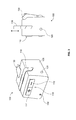
- FIG. 4 depicts a perspective view and a side view, respectively, of another example of a portable electric vehicle charging device in accord with at least some aspects of the present concepts
- FIG. 5 is an electric block diagram of one embodiment of a portable electric vehicle charging device in accord with at least some aspects of the present concepts
- FIG. 6 presents tables of alternator outputs of exemplary internal combustion engine vehicles.
- FIG. 7 is a table of charger power delivery and charging time for a variety of EV charging sources.
- FIG. 8 is a chart depicting estimates of the state of charge versus time and distance to travel versus time achievable by an embodiment of a portable electric vehicle charging device, in combination with a two different internal combustion engine vehicles, in accord with at least some aspects of the present concepts.
- FIG. 9 is a chart depicting estimates of the state of charge versus time and distance to travel versus time achievable by an embodiment of a portable electric vehicle charging device, in combination with a variety of different internal combustion engine vehicles, in accord with at least some aspects of the present concepts, in relation to other conventional charging devices.
- FIGS. 10A-10B show, for two different charging times, bar charts of estimated distances achievable by an embodiment of a portable electric vehicle charging device, in combination with a variety of different internal combustion engine vehicles, in accord with at least some aspects of the present concepts, in relation to other conventional charging devices.
- FIG. 11 shows a graph of distance versus time achievable by different EV charging sources over time, inclusive of the portable electric vehicle charging device in accord with at least some aspects of the present concepts.
- FIG. 12 shows a graph of expected distance versus time achievable by different EV charging sources over time, inclusive of the portable electric vehicle charging device in accord with at least some aspects of the present concepts, using estimates of EV battery system near-term developments in efficiency and/or materials.
- the portable EV charging device 100 includes a housing 105 , a DC input 110 having a negative terminal 112 and a positive terminal 114 , and an AC output 120 .
- the portable EV charging device 100 connected as shown in FIG. 2 , is able to pass electric current from an internal combustion vehicle 200 to an EV 300 by means of cables 142 , 152 , 125 .
- the driver of the EV can remove the portable EV charging device 100 from a stowed compartment in the vehicle and position the portable EV charging device 100 adjacent the charge port 310 .
- the driver of the EV can then enlist the assistance of a driver of an internal combustion vehicle 200 to provide, via the portable EV charging device 100 , a minimal charge from the internal combustion vehicle to the EV 300 to permit the EV to reach a charging station.
- the portable EV charging device 100 is both small and lightweight.
- the portable EV charging device 100 has a height of 8.2 inches, a length of 9.8 inches, and a width of 9.8 inches.
- the portable EV charging device 100 has a height of 13.7 inches, a length of 9.8 inches, and a width of 5.9 inches.
- the weight of both configurations is less than 15 pounds and may be less than 10 pounds.
- a variety of options, price points, and ratings may be advantageously provided to suit different needs of different end users. For example, some users may value low weight over cost and/or output while other users might value output above weight.
- the portable EV charging device 100 is readily stored in the EV 300 (or other passenger vehicle), such as in a trunk (a.k.a. boot), under the front hood (a.k.a bonnet), or in a separate compartment in the trunk, under the front hood, or in the passenger compartment.
- the negative terminal 112 and positive terminal 114 of the portable EV charging device DC input 110 are respectively electrically connected, via battery connector cables 142 , 152 , to corresponding negative and positive terminals or posts of a battery (not shown) of an internal combustion engine vehicle 200 .
- the battery connector cable 152 as shown, comprises a first end 151 connected to the negative terminal 112 of the DC input 110 via a terminal connector 150 and a second end 153 connected to the negative terminal of the vehicle 200 battery (not shown) via battery terminal connector 154 .
- the battery connector cable 142 comprises a first end 141 connected to the positive terminal 114 of the DC input 110 via a terminal connector 140 and a second end 143 connected to the positive terminal of the vehicle 200 battery (not shown) via a battery terminal connector 144 .
- the battery connector cables 142 , 152 are jumper cables (a.k.a. “jump lead” cables) having clamps at each end.
- the clamps e.g., 150 , 154
- the clamps may comprise any mechanical connector including, but not limited to, an alligator-type clamp, parrot-type clamp, or mechanic-type clamp.
- the battery connector cables 142 , 152 are between #4/0 American Wire Gauge (“AWG”) and #10 AWG, or between #2/0 AWG to #4 AWG.
- AWG American Wire Gauge
- the gauge of the battery connector cables 142 , 152 is preferably, but not necessarily, sized to correspond to the largest potential amperage expected during use (e.g., 260 amps) to enable the broadest usage of the portable EV charging device 100 with as many different internal combustion vehicles 200 as possible.
- the EV cable 125 may comprise any commercially available EV cable such as, but not limited to, the CarolGreneTM Ultra Flex® EV cables, which are compatible with conventional EV connectors (e.g., the SAE J1772 connector, or other EV connector, may be connected to the AC output 120 via such EV cable).
- EV connectors e.g., the SAE J1772 connector, or other EV connector
- the battery connector cables are integrated with the portable EV charging device 100 .
- the end 151 of battery connector cable 152 is fixed to the negative terminal 112 and the end 141 of battery connector cable 142 is fixed to the positive terminal 114 .
- the negative terminal 112 and positive terminal 114 , and corresponding ends 141 , 151 of the battery connector cables 142 , 152 may be advantageously disposed within the housing 105 .
- the portable EV charging device 100 AC output 120 may also comprise either of an EV cable 125 fixed to the AC output 120 (e.g., fixed inside of or outside of the housing 105 ) or a removable EV cable removably attached to the AC output.
- the EV cable 125 Opposite to the end of the EV cable 125 connected to the AC output 120 , the EV cable 125 comprises an EV connector 130 .
- the EV connector 130 comprises a Society of Automotive Engineers (SAE) J1772, Revision B connector (USA).
- SAE J1772 “combo” AC/DC connector In another aspect of the present concepts, the EV connector 130 comprises a SAE J1772 “combo” AC/DC connector.
- the EV connector 130 comprises any other EV plug such as, but not limited to, a Tesla plug, inductive paddles, an Avcon connector, a Dodge EV receptacle connector, a Ford Focus EV “Mule” receptacle connector, a Ford Escape receptacle 1 or 2 connector, an Aptera-2e plug, a Saturn Hybrid plug, a Concept Chevy Volt plug, a Prototype Chevy Volt plug, a Mini E plug, a Smart ED receptacle connector, a Think City receptacle connector, an Original i-MiEV 120V/240V receptacle connector, or any later developed EV connector.
- a Tesla plug inductive paddles
- an Avcon connector a Dodge EV receptacle connector
- a Ford Focus EV “Mule” receptacle connector a Ford Escape receptacle 1 or 2 connector
- an Aptera-2e plug a Saturn Hybrid plug
- the housing 105 may include one or more displays or meters (not shown) and/or one or more indicators 160 adapted to convey, to a user, information on a status of the portable EV charging device 100 and/or constituent elements thereof.
- a first LED may provide an indication as to the presence of (e.g., via an LED), or a sufficiency of (e.g., via a meter)
- a suitable DC input 110 and second LED may provide an indication as to the presence of (e.g., via an LED), or a sufficiency of (e.g., via a meter), a suitable AC output 120 .
- An on/off button and/or indicator may also be provided.
- FIG. 3 depicts a perspective view and a side view, respectively, of the portable electric vehicle charging device 100 depicted in FIG. 2 .
- the handle 116 may be movable up or down.
- the handle 116 may optionally rotate about a fixed axis or pivot points. In this way, the handle 116 may be extended and/or rotated to permit manipulation of or movement of the portable EV charging device 100 and retracted and/or rotated to minimize the overall size of the device to facilitate storage.
- FIG. 3 shows an example where an integral EV connector 130 is retained in a mating portion of the housing 105 when not in use.
- the housing 105 may optionally comprise one or more internal compartments (not shown) to store, in a stowed condition, the first battery connector cable, the second battery connector cable, and/or the EV connector.
- the housing 105 may comprise features to facilitate a placement of the portable EV charging device 100 in various positions relative to the EV 300 and/or internal combustion engine vehicle 200 when deployed.
- a bottom of the housing may comprise a rubber, high-friction bottom to permit the portable EV charging device 100 to be rested on a car without untoward risk of scratching a vehicle's paint.
- one or more securement latches could optionally be provided to assist in physically anchoring the portable EV charging device 100 in an operable position (e.g., where the vehicles are on a hill or incline).
- FIG. 4 shows a perspective view and a side view, respectively, of another example of a portable EV charging device 100 wherein the housing 105 itself defines a generally annular cable management system 160 about which one or more of the battery connector cables 142 , 152 and/or the EV cable 125 are wound during storage and secured therein.
- the circuitry between the DC input 110 and the AC output 120 is advantageously disposed within the annular hub.
- the housing 105 further defines a first handle and a second handle, generally denoted by reference numeral 116 , and the portable EV charging device 100 may be moved using one or both of the handles 116 .
- the EV connector 130 is shown in a stowed condition, locked in place in the housing 105 .
- FIG. 5 shows an electric block diagram of one embodiment of a portable electric vehicle charging device 100 .
- the upper left portion of FIG. 5 shows a vehicle DC source 95 comprising internal combustion vehicle (ICV) battery terminals.
- the positive battery terminal of the vehicle battery is connected to the vehicle alternator and the negative battery terminal is connected to ground.
- the alternator converts the mechanical energy of the internal combustion engine of vehicle 200 into AC current which is then rectified into DC current using a rectifier (e.g., diode rectifier bridge, etc.) and a voltage regulator is used to provide a substantially consistent voltage (e.g., 12.5 V or some other voltage between 12.5V and about 14.5V) at the battery terminals.
- a rectifier e.g., diode rectifier bridge, etc.
- a voltage regulator is used to provide a substantially consistent voltage (e.g., 12.5 V or some other voltage between 12.5V and about 14.5V) at the battery terminals.
- FIG. 6 presents tables of alternator outputs of exemplary internal combustion engine vehicles.
- ICV internal combustion engine
- GM General Motors
- GM General Motors
- Toyota Corolla car is shown to have an amperage of only 45 amps.
- GM General Motors
- a variety of different makes (manufacturer) and models (brands) of passenger ICVs are listed together with corresponding minimum and maximum amperages.
- the Audi A4 car is shown to have a minimum amperage of 90 amps and a maximum amperage of 150 amps
- the Ford Ka car is shown to have a minimum amperage of 70 amps and a maximum amperage of 75 amps.
- the bottom-most table of FIG. 6 shows a summary of the ranges presented in the sample population.
- a “Low Capacity” ICV provides a minimal alternator current amperage of 45 amps, corresponding to a power of 562.5 Watts (W)
- a “High Capacity” ICV provides, by way of example, a maximum alternator current amperage of 150 amps, corresponding to a power of 1875 Watts (W).
- the output power (in Watts) of the portable EV charging device 100 is different for different ICV alternators, as further described below.
- the ICV DC source 95 is shown to be connected to the DC input 110 (via terminals 112 , 114 ), at output of which is regulated by On/Off switch 500 configured to open/close the circuit.
- On/Off switch 500 Downstream of the On/Off switch 500 are conventional protective devices 505 , 510 , such as fuses and diodes, to protect the integrity of the circuit as well as connected sub-circuits, systems and components.
- the fuses protect both the charger and the battery, should any failure occur and the diodes (or similar circuits) are used to prevent any possible voltage leaking back to the battery.
- a LED status indicator 160 is provided to indicate that power is provided to the portable EV charging device 100 .
- a voltage regulator 520 is provided to maintain a constant voltage (e.g., 12.5V) for the solid-state inverter 530 , which converts the direct current to alternating current (e.g., true sine wave, a modified sine wave, or square wave output), which is changed to an appropriate voltage for output using the step-up transformer 540 .
- the inverter 530 also includes protection against over-current and may be set to around 300 amps for an inventor configured to handle charging from a “Super Duty” truck (e.g., greater than the 260 A capacity of “Super Duty” trucks).
- the step-up transformer 540 increases the voltage from the inverter to, for example, a 240 V modified sine wave form.
- the transformer is on the order of 3500 VA (e.g., higher than 12.5V*260 A).
- the inverter 530 is rated for at least about 600 Watts continuous. In other aspects of the present concepts, the inverter 530 may be rating up to any upper practical limit such as, but not limited to 3250 Watts continuous in correspondence with an upper limit of ICV alternator output.
- One exemplary inverter suitable for most applications for which the present concepts would apply may be satisfied by an inventor have a 12 VDC Input, a 240 VAC output, and a 3250 Watts power output outputting a modified sine wave or a pure sine wave.
- An example of an inverter that could be used in accord with the present concepts includes the AIMS 3600 Watt Power Inverter, Model #: pwrinv360012w.
- a harmonics filter 550 such as but not limited to a resistor-inductor (RL), is provided to eliminate or at least attenuate unwanted harmonics that come from the downstream circuit.
- the output of the RL filter 550 is output to the charging control circuit 560 , which also receives control input from a communication circuit 515 (e.g., a low amperage fuse to protect the communication and control circuit) in communication with the EV connector or plug 130 .
- the charging control circuit 560 regulates the charging of the EV 300 .
- the charging control circuit 560 performs functions including 1) establishing communication with the EV 300 , 2) permitting the inverter 530 to operate when the EV is ready to receive charge, 3) allowing the current to flow to the EV, 4) stopping the flow of the electric current whenever the user wants, 5) blocking the operation of the inverter to safely disconnect the plug and 6) ending the communication with the EV.
- the “LED COMM. Indicator” 160 indicates that the communication between the charger and the EV is being made successfully (e.g., LED blinking similar to modems and computers). If the led is steady either in ON or OFF, then it will mean that an issue has occurred.
- FIG. 7 is a table of charger power delivery and charging time for a variety of EV charging sources for a typical EV, such as a Nissan Leaf® EV.
- a typical “on board” charger configured to be attached to a 120V outlet provides between about 1200 Watts and takes from between about 20-21 hours to charge the EV. This estimate is based on a battery capacity of 24 kW and considers the time required to take an empty battery to 100% charge.
- a residential charger, such as a 240 Volt EVSE unit, can output about 3000-3300 Watts and can charge the EV in about 8 hours.
- the present concepts are not directed to fully charging a stranded vehicle, but rather to provide a sufficient rate of charge that such a stranded vehicle can receive enough of a charge from the ICV 200 to get home or to get to a charging station.
- FIG. 7 also shows the charger power delivery and charging time for the disclosed portable electric vehicle charging device 100 for a typical EV, such as a Nissan Leaf® EV.
- a typical EV such as a Nissan Leaf® EV.
- the 45 Amp alternator is only able to output about 562.5 Watts, which would yield a charging time of about 42.67 hours.
- a “High Capacity” ICV such as an Audi A4 car, with its 150 Amp alternator, is able to output about 1875 Watts, which would yield a charging time of about 12.80 hours.
- a “Super Capacity” ICV such as a Ford Super-Duty truck (e.g., 250-350 F Series) having a 200 Amp alternator, is able to output about 2500 Watts, which would yield a charging time of about 9.6 hours.
- Ford Super-Duty trucks having even higher capacity alternators, with the F550 Super-Duty truck having a 250 Amp alternator and the Ford 350F Super-Duty truck having a 260 Amp alternator.
- the estimated charge time for the EV was based on a battery capacity of 24 kW. Further, it is estimated that for a rated distance for the EV of 105.5 miles, based on an averaging of the United States EPA maximum range of 138 miles and EPA five-cycle test range of 73 miles from FIG. 1 , the average power per mile in Watts is 227 Watts for the Nissan Leaf® EV to travel one mile.
- the chart of FIG. 8 depicts estimates of the state of charge versus time and distance to travel versus time achievable by an embodiment of a portable electric vehicle charging device, in combination with a two different internal combustion engine vehicles.
- FIG. 8 shows three plots for each of an ICV “Low Capacity” ICV (e.g., a Toyota Corolla), denoted as “ICV Min”, and a “High Capacity” ICV (e.g., an Audi A4 car), denoted as “ICV Max”.
- ICV Min a linear plot, hyperbolic model plot, and an interpolated plot are provided.
- ICV Min both the leftmost plot (the hyperbolic model) and the rightmost plot (the linear model) terminate at a time of 42.67 hours for a 100% charge.
- the interpolated ICV Min plot 600 yields the same terminus in a 100% charge at 42.67 hours, but is indicated to reach a 60% charge at 12.80 hours in accord with the hyperbolic model, whereas the linear model predicts a 60% charge at 29.87 hours.
- an average Li-Ion battery reaches 60% of charge in about 1 ⁇ 3 rd the time it takes to reach a full charge.
- the interpolated ICV Max plot 610 likewise terminates in a 100% charge at 12.80 hours and indicates a 60% charge at 3.84 hours, just as predicted by the hyperbolic model.
- the ICV Min plot 600 and ICV Max plot 610 from FIG. 8 are compared in FIG. 9 to similar plots for an “On Board” Charger (plot 620 ), a residential charger (plot 630 ), and an ICV Super-Duty truck or the like (e.g., a road-assistance truck, etc.) (plot 640 ).
- the chart of FIG. 9 depicts estimates of the state of charge versus time and distance to travel versus time achievable by a portable electric vehicle charging device 100 in accord with aspects of the present concepts, in combination with a variety of different internal combustion engine vehicles 200 , in relation to an on-board charger and a residential charger.
- the interpolated ICV Min plot 600 yields a 100% charge at 42.67 hours with an indicated 60% charge at 12.80 hours.
- the interpolated ICV Max plot 610 yields a 100% charge at 12.80 hours with an indicated 60% charge at 3.84 hours.
- the interpolated ICV Max plot 610 shows enhanced performance over that of the “On Board” Charger (plot 620 ), which shows a 100% charge at 20.00 hours with an indicated 60% charge at 6.00 hours.
- the interpolated ICV Super-Duty plot 640 predicts a 100% charge at 9.60 hours with an indicated 60% charge at 2.88 hours.
- FIG. 9 shows that the residential charger, plot 630 , is only slightly better than that of the interpolated ICV Super-Duty plot 640 , with a 100% charge at 8.00 hours and an indicated 60% charge at 2.4 hours.
- FIGS. 10A-10B show, for charging times of 15 minutes and 20 minutes, respectively, bar charts of estimated distances achievable by an EV such as the Nissan Leaf® EV, following charging with a variety of EV charging devices inclusive of the portable EV charging device 100 disclosed herein.
- an EV such as the Nissan Leaf® EV
- FIG. 10A shows that the ICV Min provides, in 15 minutes, a charge that is estimated to allow the EV to travel 1.24 miles and shows that the ICV Max provides in the same time period a charge that is estimated to allow the EV to travel 4.12 miles.
- the ICV Super-Duty or the like provides, in 15 minutes, a charge that is estimated to allow the EV to travel 5.49 miles.
- the residential charger provides, in 15 minutes, a charge that is estimated to allow the EV to travel 6.59 miles.
- the EV on-board charger provides, in 15 minutes, a charge that is estimated to allow the EV to travel 2.64 miles.
- the ICV Min provides in 20 minutes a charge that is estimated to allow the EV to travel 1.65 miles and the ICV Max provides in 20 minutes a charge that is estimated to allow the EV to travel 5.49 miles.
- the ICV Super-Duty provides, in 20 minutes, a charge that is estimated to allow the EV to travel 7.33 miles.
- the residential charger provides, in 20 minutes, a charge that is estimated to allow the EV to travel 8.79 miles.
- the “On-Board” charger provides, in 20 minutes, a charge that is estimated to allow the EV to travel 3.52 miles.
- FIG. 11 shows a graph of distance versus time (for times between 0-30 minutes) achievable by different EV charging sources over time, inclusive of the portable electric vehicle charging device 100 disclosed herein.
- the output of the residential charger (plot 630 ) is a charge sufficient for the EV to travel about 13.2 miles following a charge duration of 30 minutes, about 8.79 miles following a charge duration of 20 minutes, and about 6.59 miles following a charge duration of 15 minutes.
- Plot 640 for the ICV Super-Duty truck, used in combination with the portable EV charging device 100 provides a charge sufficient for the EV to travel about 10.99 miles following a charge duration of 30 minutes, about 7.33 miles following a charge duration of 20 minutes, and about 5.49 miles following a charge duration of 15 minutes.
- Plot 640 for the ICV Super-Duty truck, used in combination with the portable EV charging device 100 also shows that this combination permits an EV to travel about 3.66 miles after a charge of only 10 minutes and about 1.83 miles after a charge of a mere 5 minutes.
- FIG. 11 also shows, in plot 610 , the results obtained by the ICV Max used in combination with the portable EV charging device 100 .
- Plot 610 shows that this combination provides a charge sufficient for the EV to travel a little over 8.00 miles following a charge duration of 30 minutes, about 5.49 miles following a charge duration of 20 minutes, and about 4.12 miles following a charge duration of 15 minutes.
- Plot 620 of FIG. 11 shows that the “on board” charger provides a charge sufficient for the EV to travel a little over 5.00 miles following a charge duration of 30 minutes, about 3.52 miles following a charge duration of 20 minutes, and about 2.64 miles following a charge duration of 15 minutes.
- plot 600 shows that the ICV Min, used in combination with the portable EV charging device 100 , provides a charge sufficient for the EV to travel a little over 2.4 miles following a charge duration of 30 minutes, about 1.65 miles following a charge duration of 20 minutes, and about 1.24 miles following a charge duration of 15 minutes.
- FIG. 12 shows a graph of expected distance versus time achievable by different EV charging sources over time, inclusive of the portable electric vehicle charging device 100 disclosed herein, using estimates of EV battery system near-term developments in efficiency and/or materials.
- Future EV-batteries are expected to include Carbon Nano-Tubes (CNT) that will increase the battery system storage capability between about 2-6 ⁇ and which will enable charging at about twice the current rate.
- CNT Carbon Nano-Tubes
- Lithium vanadium oxide is being currently tested by Subaru and appears to provide a doubled energy density.
- Silicon nanowires, silicon nanoparticles, and tin nanoparticles also promise several times the energy density in the anode, while composite and superlattice cathodes also promise significant density improvements. Additional developments are being investigated by SouthWest NanoTechnologies (SWeNT), which has developed two new grades in its SMWTM line of Specialty Multi-wall CNT. These materials are used as additives that enable higher electrical conductivity in polymer compounds and improved cathode performance in Lithium Ion batteries.
- SWeNT SouthWest NanoTechnologies
- FIG. 12 shows the expected impact of such emerging technologies when a portable EV charging device 100 in accord with the present concepts in used to charge such an EV using an internal combustion engine vehicle.
- the portable EV charging device 100 used in combination with an ICV Super-Duty truck is estimated to enable an EV to travel 14.65 miles following a 20 minute charge, as shown in plot 640 .
- the same ICV Super-Duty truck provides, via the portable EV charging device 100 , a charge sufficient for the EV to travel about 7.33 miles following a charge duration of a mere 10 minutes and to travel about 3.66 miles following a charge duration of only 5 minutes, as shown in plot 640 .
- plot 610 for an “ICV Max” using the portable EV charging device 100 , a mere 10 minute charge would be sufficient for the EV to travel about 5.49 miles. Additional plots are presented in FIG. 12 showing the expected impact of such emerging technologies on the on-board charger (plot 620 ) and residential charger (plot 630 ).
- the present concepts therefore provide a device by which many internal combustion vehicles can easily render assistance to a stranded EV and, within a relatively short period of 15-20 minutes, enable the stranded EV to reach a suitable charging station.
Abstract
Description
Claims (19)
Applications Claiming Priority (1)
| Application Number | Priority Date | Filing Date | Title |
|---|---|---|---|
| PCT/US2013/032294 WO2014143006A1 (en) | 2013-03-15 | 2013-03-15 | Portable electric vehicle charging device |
Publications (2)
| Publication Number | Publication Date |
|---|---|
| US20160023562A1 US20160023562A1 (en) | 2016-01-28 |
| US9963038B2 true US9963038B2 (en) | 2018-05-08 |
Family
ID=51537362
Family Applications (1)
| Application Number | Title | Priority Date | Filing Date |
|---|---|---|---|
| US14/774,915 Active 2034-01-09 US9963038B2 (en) | 2013-03-15 | 2013-03-15 | Portable electric vehicle charging device |
Country Status (2)
| Country | Link |
|---|---|
| US (1) | US9963038B2 (en) |
| WO (1) | WO2014143006A1 (en) |
Cited By (6)
| Publication number | Priority date | Publication date | Assignee | Title |
|---|---|---|---|---|
| US20170203666A1 (en) * | 2016-01-19 | 2017-07-20 | Ford Global Technologies, Llc | Battery charging system and servicing method |
| CN111746327A (en) * | 2020-07-10 | 2020-10-09 | 贾智聪 | Movable new energy automobile fills electric pile |
| US11104244B2 (en) * | 2019-04-12 | 2021-08-31 | Ford Global Technologies, Llc | Method for charging a plug-in electric vehicle via another plug-in electric vehicle |
| US11152814B2 (en) | 2019-11-22 | 2021-10-19 | GM Global Technology Operations LLC | Mobile charging stations with fuel-cell generators for electric-drive vehicles |
| US11447016B2 (en) * | 2019-11-01 | 2022-09-20 | Ford Global Technologies, Llc | System and method for battery preconditioning based on selected regenerative braking amount |
| US11827117B2 (en) | 2021-11-05 | 2023-11-28 | GM Global Technology Operations LLC | Intelligent charging systems and control logic for crowdsourced vehicle energy transfer |
Families Citing this family (17)
| Publication number | Priority date | Publication date | Assignee | Title |
|---|---|---|---|---|
| US9260024B1 (en) * | 2013-11-17 | 2016-02-16 | Lawrence Michael Lau | Distance-based charging for electric vehicles |
| US9616752B2 (en) * | 2014-02-12 | 2017-04-11 | Caterpillar Inc. | Electrical power supply system for a machine |
| US20160020618A1 (en) * | 2014-07-21 | 2016-01-21 | Ford Global Technologies, Llc | Fast Charge Algorithms for Lithium-Ion Batteries |
| DE102014226031A1 (en) * | 2014-12-16 | 2016-06-16 | Volkswagen Aktiengesellschaft | Method and device for predicting a range of a vehicle with at least partially electric drive |
| FR3031846B1 (en) * | 2015-01-16 | 2017-02-03 | Adetel Equipment | SYSTEM FOR LOADING ELECTRIC ENERGY STORAGE ELEMENTS OF A VEHICLE |
| CN105398888A (en) * | 2015-12-07 | 2016-03-16 | 湖南深拓智能设备股份有限公司 | Combined cable reel special for emergency rescue charging trolley of electric automobile |
| US10302496B2 (en) * | 2016-02-09 | 2019-05-28 | Nasa Solutions, Llc | Method and apparatus for determining presence and operation of a component in a printed circuit board |
| CN107867186B (en) * | 2016-09-27 | 2021-02-23 | 华为技术有限公司 | Electric automobile and method for charging among electric automobiles |
| KR101948252B1 (en) * | 2017-03-24 | 2019-02-14 | 현대자동차주식회사 | Electric vehicle and battery charging method of vehicle |
| EP3401993A1 (en) * | 2017-05-08 | 2018-11-14 | volabo GmbH | Battery for an electric vehicle |
| CN108054793B (en) * | 2017-12-07 | 2021-02-02 | 中山市天隆燃具电器有限公司 | Hidden new energy automobile fills electric pile |
| US11837895B2 (en) * | 2019-11-04 | 2023-12-05 | Ox Partners, Llc | Smart jumper cables |
| DE102020112804A1 (en) * | 2020-05-12 | 2021-11-18 | Innogy Se | Jump leads |
| US11264825B1 (en) | 2020-08-31 | 2022-03-01 | Ford Global Technologies, Llc | Vehicle to vehicle high power charging |
| US11745614B2 (en) | 2020-10-26 | 2023-09-05 | Ford Global Technologies, Llc | Portable high-voltage vehicle charging system |
| WO2022191720A1 (en) * | 2021-03-12 | 2022-09-15 | Ubco Limited | Improvements in and relating to battery power supply parts and fittings therefor |
| TWI785548B (en) * | 2021-03-26 | 2022-12-01 | 拓連科技股份有限公司 | Electric vehicle supply equipment with power-off protection mechanism and methods thereof |
Citations (19)
| Publication number | Priority date | Publication date | Assignee | Title |
|---|---|---|---|---|
| US5581171A (en) | 1994-06-10 | 1996-12-03 | Northrop Grumman Corporation | Electric vehicle battery charger |
| US6636015B1 (en) * | 2002-05-09 | 2003-10-21 | Team Products International Inc. | Watertight portable auxiliary power source |
| US20040262062A1 (en) | 2003-06-26 | 2004-12-30 | Berbari George Edmond | Flywheel-driven vehicle |
| US7057371B2 (en) | 2004-04-19 | 2006-06-06 | General Motors Corporation | Inverter for electric and hybrid powered vehicles and associated system and method |
| US20110055037A1 (en) * | 2009-08-11 | 2011-03-03 | Larry Hayashigawa | Stored energy and charging appliance |
| US20120109763A1 (en) * | 2010-11-02 | 2012-05-03 | Lisa Mae Laughner | Mobile Charging of Electric Vehicles Off the Electric Power Grid |
| US20120206100A1 (en) | 2010-01-11 | 2012-08-16 | Leviton Manufacturing Co., Inc. | Electric vehicle supply equipment |
| US20120286720A1 (en) * | 2009-09-02 | 2012-11-15 | Jochen Fassnacht | Jump-starting method and device for implementing the method |
| WO2012154990A2 (en) | 2011-05-10 | 2012-11-15 | Johnsen Stephen G | Mobile variable power system and method |
| US20120303397A1 (en) * | 2011-05-25 | 2012-11-29 | Green Charge Networks Llc | Charging Service Vehicle Network |
| US20120315801A1 (en) | 2011-06-13 | 2012-12-13 | Lear Corporation | Connector assembly for vehicle charging |
| US20130020993A1 (en) * | 2011-07-18 | 2013-01-24 | Green Charge Networks Llc | Multi-Mode Electric Vehicle Charging Station |
| US20130076123A1 (en) * | 2011-09-28 | 2013-03-28 | Takafumi Suzuki | Secure power source structure for startup of electric power supply device |
| US20130175990A1 (en) * | 2010-09-03 | 2013-07-11 | Bayerische Motoren Werke Aktiengesellschaft | System for Charging a Rechargeable Battery of an Electric Vehicle |
| US20130187449A1 (en) * | 2012-01-24 | 2013-07-25 | Honda Motor Co., Ltd | Vehicle power supply system |
| US20150015183A1 (en) * | 2013-07-15 | 2015-01-15 | Ford Global Technologies, Llc | Battery electric vehicle jumper cable and jump starting method |
| US20150217656A1 (en) * | 2014-01-31 | 2015-08-06 | Ford Global Technologies, Llc | Portable EV Energy Transfer Apparatus and Method |
| US9266438B2 (en) * | 2012-01-09 | 2016-02-23 | Tata Technologies Pte Ltd | Buddy charging for electric vehicles |
| US9509144B1 (en) * | 2011-11-19 | 2016-11-29 | Lex Products | Universal powering station and a method for implementing same |
-
2013
- 2013-03-15 WO PCT/US2013/032294 patent/WO2014143006A1/en active Application Filing
- 2013-03-15 US US14/774,915 patent/US9963038B2/en active Active
Patent Citations (20)
| Publication number | Priority date | Publication date | Assignee | Title |
|---|---|---|---|---|
| US5581171A (en) | 1994-06-10 | 1996-12-03 | Northrop Grumman Corporation | Electric vehicle battery charger |
| US6636015B1 (en) * | 2002-05-09 | 2003-10-21 | Team Products International Inc. | Watertight portable auxiliary power source |
| US20040262062A1 (en) | 2003-06-26 | 2004-12-30 | Berbari George Edmond | Flywheel-driven vehicle |
| US7057371B2 (en) | 2004-04-19 | 2006-06-06 | General Motors Corporation | Inverter for electric and hybrid powered vehicles and associated system and method |
| US20110055037A1 (en) * | 2009-08-11 | 2011-03-03 | Larry Hayashigawa | Stored energy and charging appliance |
| US20120286720A1 (en) * | 2009-09-02 | 2012-11-15 | Jochen Fassnacht | Jump-starting method and device for implementing the method |
| US20120206100A1 (en) | 2010-01-11 | 2012-08-16 | Leviton Manufacturing Co., Inc. | Electric vehicle supply equipment |
| US20130175990A1 (en) * | 2010-09-03 | 2013-07-11 | Bayerische Motoren Werke Aktiengesellschaft | System for Charging a Rechargeable Battery of an Electric Vehicle |
| US20120109763A1 (en) * | 2010-11-02 | 2012-05-03 | Lisa Mae Laughner | Mobile Charging of Electric Vehicles Off the Electric Power Grid |
| WO2012154990A2 (en) | 2011-05-10 | 2012-11-15 | Johnsen Stephen G | Mobile variable power system and method |
| US20120303397A1 (en) * | 2011-05-25 | 2012-11-29 | Green Charge Networks Llc | Charging Service Vehicle Network |
| US20120315801A1 (en) | 2011-06-13 | 2012-12-13 | Lear Corporation | Connector assembly for vehicle charging |
| US20130020993A1 (en) * | 2011-07-18 | 2013-01-24 | Green Charge Networks Llc | Multi-Mode Electric Vehicle Charging Station |
| US20130076123A1 (en) * | 2011-09-28 | 2013-03-28 | Takafumi Suzuki | Secure power source structure for startup of electric power supply device |
| US9509144B1 (en) * | 2011-11-19 | 2016-11-29 | Lex Products | Universal powering station and a method for implementing same |
| US9266438B2 (en) * | 2012-01-09 | 2016-02-23 | Tata Technologies Pte Ltd | Buddy charging for electric vehicles |
| US20130187449A1 (en) * | 2012-01-24 | 2013-07-25 | Honda Motor Co., Ltd | Vehicle power supply system |
| US9623752B2 (en) * | 2012-01-24 | 2017-04-18 | Honda Motor Co., Ltd. | Vehicle power supply system |
| US20150015183A1 (en) * | 2013-07-15 | 2015-01-15 | Ford Global Technologies, Llc | Battery electric vehicle jumper cable and jump starting method |
| US20150217656A1 (en) * | 2014-01-31 | 2015-08-06 | Ford Global Technologies, Llc | Portable EV Energy Transfer Apparatus and Method |
Non-Patent Citations (1)
| Title |
|---|
| International Search Report and Written Opinion dated Jun. 11, 2013 in International Application No. PCT/US13/32294, 12 pages. |
Cited By (6)
| Publication number | Priority date | Publication date | Assignee | Title |
|---|---|---|---|---|
| US20170203666A1 (en) * | 2016-01-19 | 2017-07-20 | Ford Global Technologies, Llc | Battery charging system and servicing method |
| US11104244B2 (en) * | 2019-04-12 | 2021-08-31 | Ford Global Technologies, Llc | Method for charging a plug-in electric vehicle via another plug-in electric vehicle |
| US11447016B2 (en) * | 2019-11-01 | 2022-09-20 | Ford Global Technologies, Llc | System and method for battery preconditioning based on selected regenerative braking amount |
| US11152814B2 (en) | 2019-11-22 | 2021-10-19 | GM Global Technology Operations LLC | Mobile charging stations with fuel-cell generators for electric-drive vehicles |
| CN111746327A (en) * | 2020-07-10 | 2020-10-09 | 贾智聪 | Movable new energy automobile fills electric pile |
| US11827117B2 (en) | 2021-11-05 | 2023-11-28 | GM Global Technology Operations LLC | Intelligent charging systems and control logic for crowdsourced vehicle energy transfer |
Also Published As
| Publication number | Publication date |
|---|---|
| WO2014143006A1 (en) | 2014-09-18 |
| US20160023562A1 (en) | 2016-01-28 |
Similar Documents
| Publication | Publication Date | Title |
|---|---|---|
| US9963038B2 (en) | Portable electric vehicle charging device | |
| US9056552B2 (en) | Method and system for charging a plug-in electric vehicle | |
| US20130026989A1 (en) | Vehicle battery and method of charging the same | |
| US9637019B2 (en) | System and method for charging a plug-in electric vehicle | |
| Dixon et al. | Electric vehicle using a combination of ultracapacitors and ZEBRA battery | |
| US9630513B2 (en) | Portable bi-directional multiport AC/DC charging cable system | |
| US20230231395A1 (en) | Battery system | |
| WO2014163618A1 (en) | Inter-protocol charging adapter | |
| CN205375053U (en) | Electric automobile high pressure integrated control system | |
| CN105359377A (en) | Charging device and vehicle | |
| CN104602946A (en) | Manufacturing service disconnect that is part of busbar | |
| Becherif et al. | Design and sizing of a stand-alone recharging point for battery electrical vehicles using photovoltaic energy | |
| Macharia et al. | A review of electric vehicle technology: Architectures, battery technology and its management system, relevant standards, application of artificial intelligence, cyber security, and interoperability challenges | |
| CN208324913U (en) | On-board charging system and automobile | |
| CN209552971U (en) | Pure electric vehicle mobile power vehicle | |
| Dujic | Electric vehicles charging-an ultrafast overview | |
| Kurfirt et al. | E-mobility impact on supply in distribution grid | |
| Rathore et al. | Advanced Concepts and Technologies for Electric Vehicles | |
| CN109895631A (en) | Intelligent double-power management method, system and the computer readable storage medium of new-energy automobile | |
| Leemput | Grid-supportive charging infrastructure for plug-in electric vehicles | |
| Wagh et al. | A review on powertrain subsystems and charging technology in battery electric vehicles: Current and future trends | |
| CN111942187A (en) | Pure electric university student formula car with wireless charging technology | |
| CN204947700U (en) | A kind of common-battery system | |
| Cities | Hybrid and Plug-In Electric Vehicles | |
| Madichetty et al. | Route Towards Road Freight Electrification in India: Examining Battery Electric Truck Powertrain and Energy Consumption |
Legal Events
| Date | Code | Title | Description |
|---|---|---|---|
| AS | Assignment |
Owner name: SCHNEIDER R&D, S.A. DE C.V., MEXICO Free format text: ASSIGNMENT OF ASSIGNORS INTEREST;ASSIGNORS:ORTIZ, JOSE ENRIQUE PARRA;ELIZONDO, JOSE GERARDO MUNIZ;REEL/FRAME:033992/0186 Effective date: 20130322 Owner name: SCHNEIDER ELECTRIC USA, INC., ILLINOIS Free format text: ASSIGNMENT OF ASSIGNORS INTEREST;ASSIGNOR:SCHNEIDER R&D, S.A. DE C.V.;REEL/FRAME:033992/0268 Effective date: 20130603 |
|
| AS | Assignment |
Owner name: SCHNEIDER ELECTRIC USA, INC., ILLINOIS Free format text: ASSIGNMENT OF ASSIGNORS INTEREST;ASSIGNOR:SCHNEIDER R&D, S.A. DE C.V.;REEL/FRAME:036589/0969 Effective date: 20130603 Owner name: SCHNEIDER R&D, S.A. DE C.V., MEXICO Free format text: ASSIGNMENT OF ASSIGNORS INTEREST;ASSIGNORS:PARRA ORTIZ, JOSE ENRIQUE;MUNIZ ELIZONDO, JOSE GERARDO;REEL/FRAME:036589/0908 Effective date: 20130322 |
|
| STCF | Information on status: patent grant |
Free format text: PATENTED CASE |
|
| MAFP | Maintenance fee payment |
Free format text: PAYMENT OF MAINTENANCE FEE, 4TH YEAR, LARGE ENTITY (ORIGINAL EVENT CODE: M1551); ENTITY STATUS OF PATENT OWNER: LARGE ENTITY Year of fee payment: 4 |