EP3033248B1 - Method for controlling a headlight arrangement for a vehicle and such a headlight arrangement - Google Patents
Method for controlling a headlight arrangement for a vehicle and such a headlight arrangement Download PDFInfo
- Publication number
- EP3033248B1 EP3033248B1 EP14736702.3A EP14736702A EP3033248B1 EP 3033248 B1 EP3033248 B1 EP 3033248B1 EP 14736702 A EP14736702 A EP 14736702A EP 3033248 B1 EP3033248 B1 EP 3033248B1
- Authority
- EP
- European Patent Office
- Prior art keywords
- light
- light distribution
- partial
- vehicle
- partial light
- Prior art date
- Legal status (The legal status is an assumption and is not a legal conclusion. Google has not performed a legal analysis and makes no representation as to the accuracy of the status listed.)
- Active
Links
- 238000000034 method Methods 0.000 title claims description 20
- 238000009826 distribution Methods 0.000 claims description 234
- 239000011159 matrix material Substances 0.000 claims description 15
- 238000005286 illumination Methods 0.000 description 23
- 230000008901 benefit Effects 0.000 description 5
- 230000001105 regulatory effect Effects 0.000 description 5
- 230000001419 dependent effect Effects 0.000 description 3
- 238000006073 displacement reaction Methods 0.000 description 3
- 230000003287 optical effect Effects 0.000 description 3
- 206010052128 Glare Diseases 0.000 description 2
- 230000007423 decrease Effects 0.000 description 2
- 230000003247 decreasing effect Effects 0.000 description 2
- 238000011161 development Methods 0.000 description 2
- 230000018109 developmental process Effects 0.000 description 2
- 230000007704 transition Effects 0.000 description 2
- 230000004913 activation Effects 0.000 description 1
- 230000006978 adaptation Effects 0.000 description 1
- 238000003491 array Methods 0.000 description 1
- 230000000712 assembly Effects 0.000 description 1
- 238000000429 assembly Methods 0.000 description 1
- 230000015572 biosynthetic process Effects 0.000 description 1
- 230000008859 change Effects 0.000 description 1
- 238000006243 chemical reaction Methods 0.000 description 1
- 230000001276 controlling effect Effects 0.000 description 1
- 230000000694 effects Effects 0.000 description 1
- 238000005516 engineering process Methods 0.000 description 1
- 230000012447 hatching Effects 0.000 description 1
- 230000000873 masking effect Effects 0.000 description 1
- 230000008569 process Effects 0.000 description 1
Images


Classifications
-
- B—PERFORMING OPERATIONS; TRANSPORTING
- B60—VEHICLES IN GENERAL
- B60Q—ARRANGEMENT OF SIGNALLING OR LIGHTING DEVICES, THE MOUNTING OR SUPPORTING THEREOF OR CIRCUITS THEREFOR, FOR VEHICLES IN GENERAL
- B60Q1/00—Arrangement of optical signalling or lighting devices, the mounting or supporting thereof or circuits therefor
- B60Q1/02—Arrangement of optical signalling or lighting devices, the mounting or supporting thereof or circuits therefor the devices being primarily intended to illuminate the way ahead or to illuminate other areas of way or environments
- B60Q1/04—Arrangement of optical signalling or lighting devices, the mounting or supporting thereof or circuits therefor the devices being primarily intended to illuminate the way ahead or to illuminate other areas of way or environments the devices being headlights
- B60Q1/14—Arrangement of optical signalling or lighting devices, the mounting or supporting thereof or circuits therefor the devices being primarily intended to illuminate the way ahead or to illuminate other areas of way or environments the devices being headlights having dimming means
- B60Q1/1415—Dimming circuits
- B60Q1/1423—Automatic dimming circuits, i.e. switching between high beam and low beam due to change of ambient light or light level in road traffic
- B60Q1/143—Automatic dimming circuits, i.e. switching between high beam and low beam due to change of ambient light or light level in road traffic combined with another condition, e.g. using vehicle recognition from camera images or activation of wipers
-
- F—MECHANICAL ENGINEERING; LIGHTING; HEATING; WEAPONS; BLASTING
- F21—LIGHTING
- F21S—NON-PORTABLE LIGHTING DEVICES; SYSTEMS THEREOF; VEHICLE LIGHTING DEVICES SPECIALLY ADAPTED FOR VEHICLE EXTERIORS
- F21S41/00—Illuminating devices specially adapted for vehicle exteriors, e.g. headlamps
- F21S41/10—Illuminating devices specially adapted for vehicle exteriors, e.g. headlamps characterised by the light source
- F21S41/14—Illuminating devices specially adapted for vehicle exteriors, e.g. headlamps characterised by the light source characterised by the type of light source
- F21S41/141—Light emitting diodes [LED]
- F21S41/143—Light emitting diodes [LED] the main emission direction of the LED being parallel to the optical axis of the illuminating device
-
- F—MECHANICAL ENGINEERING; LIGHTING; HEATING; WEAPONS; BLASTING
- F21—LIGHTING
- F21S—NON-PORTABLE LIGHTING DEVICES; SYSTEMS THEREOF; VEHICLE LIGHTING DEVICES SPECIALLY ADAPTED FOR VEHICLE EXTERIORS
- F21S41/00—Illuminating devices specially adapted for vehicle exteriors, e.g. headlamps
- F21S41/10—Illuminating devices specially adapted for vehicle exteriors, e.g. headlamps characterised by the light source
- F21S41/14—Illuminating devices specially adapted for vehicle exteriors, e.g. headlamps characterised by the light source characterised by the type of light source
- F21S41/141—Light emitting diodes [LED]
- F21S41/151—Light emitting diodes [LED] arranged in one or more lines
- F21S41/153—Light emitting diodes [LED] arranged in one or more lines arranged in a matrix
-
- F—MECHANICAL ENGINEERING; LIGHTING; HEATING; WEAPONS; BLASTING
- F21—LIGHTING
- F21S—NON-PORTABLE LIGHTING DEVICES; SYSTEMS THEREOF; VEHICLE LIGHTING DEVICES SPECIALLY ADAPTED FOR VEHICLE EXTERIORS
- F21S41/00—Illuminating devices specially adapted for vehicle exteriors, e.g. headlamps
- F21S41/60—Illuminating devices specially adapted for vehicle exteriors, e.g. headlamps characterised by a variable light distribution
- F21S41/65—Illuminating devices specially adapted for vehicle exteriors, e.g. headlamps characterised by a variable light distribution by acting on light sources
- F21S41/657—Illuminating devices specially adapted for vehicle exteriors, e.g. headlamps characterised by a variable light distribution by acting on light sources by moving light sources
-
- F—MECHANICAL ENGINEERING; LIGHTING; HEATING; WEAPONS; BLASTING
- F21—LIGHTING
- F21S—NON-PORTABLE LIGHTING DEVICES; SYSTEMS THEREOF; VEHICLE LIGHTING DEVICES SPECIALLY ADAPTED FOR VEHICLE EXTERIORS
- F21S41/00—Illuminating devices specially adapted for vehicle exteriors, e.g. headlamps
- F21S41/60—Illuminating devices specially adapted for vehicle exteriors, e.g. headlamps characterised by a variable light distribution
- F21S41/65—Illuminating devices specially adapted for vehicle exteriors, e.g. headlamps characterised by a variable light distribution by acting on light sources
- F21S41/663—Illuminating devices specially adapted for vehicle exteriors, e.g. headlamps characterised by a variable light distribution by acting on light sources by switching light sources
-
- F—MECHANICAL ENGINEERING; LIGHTING; HEATING; WEAPONS; BLASTING
- F21—LIGHTING
- F21S—NON-PORTABLE LIGHTING DEVICES; SYSTEMS THEREOF; VEHICLE LIGHTING DEVICES SPECIALLY ADAPTED FOR VEHICLE EXTERIORS
- F21S41/00—Illuminating devices specially adapted for vehicle exteriors, e.g. headlamps
- F21S41/60—Illuminating devices specially adapted for vehicle exteriors, e.g. headlamps characterised by a variable light distribution
- F21S41/68—Illuminating devices specially adapted for vehicle exteriors, e.g. headlamps characterised by a variable light distribution by acting on screens
- F21S41/683—Illuminating devices specially adapted for vehicle exteriors, e.g. headlamps characterised by a variable light distribution by acting on screens by moving screens
- F21S41/686—Blades, i.e. screens moving in a vertical plane
-
- B—PERFORMING OPERATIONS; TRANSPORTING
- B60—VEHICLES IN GENERAL
- B60Q—ARRANGEMENT OF SIGNALLING OR LIGHTING DEVICES, THE MOUNTING OR SUPPORTING THEREOF OR CIRCUITS THEREFOR, FOR VEHICLES IN GENERAL
- B60Q2300/00—Indexing codes for automatically adjustable headlamps or automatically dimmable headlamps
- B60Q2300/05—Special features for controlling or switching of the light beam
- B60Q2300/056—Special anti-blinding beams, e.g. a standard beam is chopped or moved in order not to blind
-
- B—PERFORMING OPERATIONS; TRANSPORTING
- B60—VEHICLES IN GENERAL
- B60Q—ARRANGEMENT OF SIGNALLING OR LIGHTING DEVICES, THE MOUNTING OR SUPPORTING THEREOF OR CIRCUITS THEREFOR, FOR VEHICLES IN GENERAL
- B60Q2300/00—Indexing codes for automatically adjustable headlamps or automatically dimmable headlamps
- B60Q2300/40—Indexing codes relating to other road users or special conditions
- B60Q2300/41—Indexing codes relating to other road users or special conditions preceding vehicle
-
- B—PERFORMING OPERATIONS; TRANSPORTING
- B60—VEHICLES IN GENERAL
- B60Q—ARRANGEMENT OF SIGNALLING OR LIGHTING DEVICES, THE MOUNTING OR SUPPORTING THEREOF OR CIRCUITS THEREFOR, FOR VEHICLES IN GENERAL
- B60Q2300/00—Indexing codes for automatically adjustable headlamps or automatically dimmable headlamps
- B60Q2300/40—Indexing codes relating to other road users or special conditions
- B60Q2300/42—Indexing codes relating to other road users or special conditions oncoming vehicle
Definitions
- the present invention relates to a method for controlling a headlamp assembly for a vehicle having the features of the preamble of claim 1.
- the headlights of a vehicle have the task, in poor visibility, especially in the dark, the environment in the direction of the vehicle, in particular the road, illuminate.
- the headlights serve as a distinguishing feature for other road users.
- the headlamp is based on a mechanical system in which the masking can be realized by movable in the beam path screens and headlamp leveling by pivoting the headlamp.
- This light distribution is referred to in the documents and also in the following as a masked long-distance light.
- the light distribution generated by this mechanical system encounters especially in the outer areas of the light distribution due to technical limitations and optical Properties to its limits. As a rule, sufficient lighting can no longer be provided there.
- matrix headlights which have light sources arranged in a matrix.
- the light sources in matrix headlights are usually light emitting diodes.
- the technology of matrix headlights is therefore generally based on purely electronic processes. Examples of matrix headlights and methods for their control are from the publications DE 100 09 782 A1 . DE 10 2009 060 781 A1 and DE 10 2011 112 716 A1 known.
- matrix headlamps are very expensive due to the high cost of light emitting diodes.
- LED matrix spotlights also have disadvantages, such as increased heat development in the headlight. Furthermore, by an arrangement of the LEDs in rows a recognizable inhomogeneous strip-like light distribution.
- the publication DE 10 2008 036 193 A1 is a method with the features of the preamble of claim 1 and a headlamp assembly with the features of the preamble to refer.
- the pamphlets DE 20 2010 001 654 U1 such as EP 2 221 218 A1 reveal headlamps with movable panels and LED arrays having light modules in which a total light distribution can be generated by superposition of partial light distributions, which on the one hand in the high beam operation provides better illumination, on the other hand reduces the risk of dazzling other road users.
- a headlamp for a vehicle in which held by a movable member on a pivotable support light-emitting diodes can be shaded so that their light falls only on portions of a reflective surface.
- a glare-free overall light distribution can be generated.
- a first partial light distribution of a light function of the first modules by changing a position of the at least one movable Produces elements generates a second partial light distribution of the same light function of the second modules by driving individual light sources or groups of light sources of the plurality of light sources, and the total light distribution of the light function is generated by the first partial light distribution and the second partial light distribution are superimposed.
- the movable element may be meant by changing a position of the at least one movable element and a rotation about an axis of the movable element.
- the method has the advantage that the light function is generated by a combination of a partial light distribution generated by a mechanically operated module and a partial light distribution generated by an electronically operated module.
- the advantages of both technical properties can be exploited.
- the strip-like light distribution which is formed for example by a light-emitting diode matrix, smoothed by the superposition of the light distribution of the mechanically operated module. As a result, a high homogeneity of the light distribution is achieved.
- At least one road user is detected in the direction of the light emission of the headlamp assembly.
- the first partial light distribution is then controlled such that it has a central area with a luminous beam that is less than the distance to the detected road user, and two side areas, which are generated on both sides next to the central area, with headlights that are greater than the distance to the registered road user.
- the second partial light distribution is regulated in such a way that it has headlight ranges which are greater than the distance to the detected road user only in the side areas of the first partial light distribution.
- a horizontal light-dark boundary is formed in front of the detected road user and a vertical light-dark boundary is formed next to the detected road user and the higher light range in the area next to the detected road user.
- the headlight range in the central region which in the second overall light distribution extends in particular to the detected road user, is preferably regulated by an already existing headlight range control. Since the bright-dark border in the middle area is provided only by the first module, can this headlamp leveling can be achieved by pivoting only the first module.
- the term " headlight range” is understood to mean an angle-dependent distance on the road in which the light intensity falls below a limit value. At distances that extend beyond the beam range, the light intensity is particularly low so that other road users are no longer dazzled.
- the angle is a horizontal angle formed by a longitudinal axis through a headlamp or headlamp assembly and a connecting line from a point on the cut-off line and the intersection of the longitudinal axis with a transverse axis passing through the headlamp or headlamp assembly becomes.
- the light-dark boundary of the total light distribution is divided into a vehicle-related and a vehicle-distant region, wherein the vehicle-near region is generated by the first partial light distribution and the vehicle-distant region by the second partial light distribution.
- the second partial light distribution can be wider where the width of the light-dark boundary of the first partial light distribution already narrows or does not widen further due to technical limitations of the mechanically operated module. For the vehicle-distant area, this therefore means a broader overall light distribution, which provides better illumination in the side areas.
- a light-free corridor is formed by the central area and the side areas in the total light distribution, the light-free corridor having an edge created from the central area transverse to the vehicle and two edges longitudinally from the vehicle to the vehicle Side edges are generated substantially by the second partial light distribution and the distance in the transverse direction between the edges generated by the side regions depends on the width of the detected road user. If the edges generated by the side regions are generated essentially by the second partial light distribution, this has the advantage that the light-free corridor can be brought close to the detected road user. This is possible because rows of light sources selected by the matrix of light sources generate the side areas, which in turn are the edges of the side areas produce. As a result, a substantially linear light emission is possible, which can bring the edges of the side areas up to a few cm to the detected road users. As a result, there are no major gaps in the overall light distribution except for the light-free corridor.
- the range of the first partial light distribution in at least one side area is lowered in such a way that from a certain angle the side area is generated only by the second partial light distribution.
- the lowering of the beam range is limited in at least one area by the technical limits of mechanically controlled modules and by the optical properties of movable elements that are introduced into beam paths. Namely, the change of the position of movable elements in a beam path leads to significant changes in the light distribution, especially in the far distance.
- the second partial light distribution can provide illumination there. This in turn ensures a more complete illumination of the environment.
- the second partial light distribution of at least two light beams is generated, wherein at least one of these two light beams is divided into two partial light beams depending on the horizontal angle between the direction of travel of the vehicle and the connecting line from the vehicle to the detected road user, so that a partial light beam the one Generated side area alone and the other partial light beam generated the other side area together at least with the other light beam of the second partial light distribution.
- the one light beam is generated in particular by the second module of the right headlamp and the other light beam by the second module of the left headlamp. This can advantageously be ensured that other road users are not dazzled even in tight bends or at short distances to oncoming traffic participants.
- the second partial light distribution in the side areas is divided into a plurality of partial areas, wherein the brightness drops from the innermost partial area to the outermost partial area.
- the light function is a high beam function. This is advantageous because then also on routes that are poorly lit, such as highways and highways on which a low beam function does not provide sufficient illumination, a comprehensive lighting of the environment can be provided.
- a headlight assembly for a vehicle is provided.
- the headlight assembly according to the invention has at least two spaced headlamps, by means of which an overall light distribution can be generated, wherein both headlamps each comprise at least a first and a second module, which are arranged separately from each other.
- the first module in each case comprises at least one light source and at least one movable element, which can be brought into the beam path of the light emitted by the light source.
- the second module each comprises a plurality of light sources arranged in a matrix.
- the headlight assembly has a control device with which the first modules are controlled so that by changing a position of the at least one movable element, a first partial light distribution of a light function can be generated, and with which the second module is so controlled that by driving individual Light sources or groups of light sources of the plurality of light sources, a second partial light distribution of the same light function can be generated.
- the control device With the control device, the headlights are further controlled so that the total light distribution can be generated by superimposing the first and the second partial light distribution.
- the headlight assembly according to the invention is designed so that it can perform the inventive method completely.
- the headlamp assembly additionally has a device for detecting road users in the direction of travel in front of the vehicle.
- the control device is then also coupled to the device for detecting, for example via a second control device.
- the at least one light source of the first module and / or the plurality of light sources of the second module are light-emitting diodes.
- the movable element of the first module may comprise variable aperture stops.
- the movable element may also be a diaphragm shaft with separate shaft sections, wherein the separate Shaft sections have different focal lines. In this case, the first partial light distribution can be generated with at least one of these focal lines.
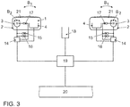
- the headlamp assembly generally in FIG. 3 is shown comprises two spaced headlights 1 and 2, which are arranged in front on the right and left side of the vehicle in a known per se.
- One of these headlights 1, 2 is in Fig. 1 shown.
- the arranged on the other side headlight 2 is mirror-inverted constructed substantially identical.
- FIG. 1 is a section through the left headlamp 1 shown in a plane which is parallel to the plane spanned by the vehicle transverse axis QA and the vertical V plane.
- the headlamp 1 comprises a first 3 and a second module 4. With the first module 3, a first partial light distribution and with the second module, a second partial light distribution can be generated, which generate an identical light function.
- the headlight 1 comprises additional modules 5 and 6, by means of which additional lighting functions can be realized.
- the module 5, for example, realize a cornering light and the module 6 provide an apron illumination of a low beam function.
- the first module 3 is designed as a projection module.
- the first module 3 comprises, in a manner known per se, a light source 7 which is surrounded by a reflector 8 designed as an ellipsoid of revolution.
- the reflector 8 thus has two focal points.
- the light source 7 is located in one of the focal points of the reflector 8.
- the light emitted by the light source 7 is reflected by the reflector 8 in the light emission direction L of the first module 3 in the direction of a projection lens 9.
- a diaphragm arrangement with the areal diaphragms 10 and 11 is arranged at the focal point of the projection lens 9 and close to the second focal point of the reflector 8.
- the normals of the areal apertures 10 and 11 are aligned substantially parallel to the light emission direction L.
- the light source 7, the reflector 8, the lens 9 and the apertures 10, 11 are arranged within a housing 12.
- the shape of the light-dark boundary of the first partial light distribution of the first module 3 can be changed by moving the diaphragms 10 and 11 in the vertical and / or horizontal direction in the beam path of the light emitted by the light source 7.
- the apertures 10 and 11 both a vertical and a horizontal cut-off line can be generated, whereby the vertical cut-off line can be shifted substantially steplessly to the left and right and the horizontal cut-off line in the Essentially infinitely shift up and down.
- a shift of the horizontal cut-off line also becomes by pivoting the first module 3 about a horizontal axis realized.
- An aperture 11, which is movable in the horizontal direction in the beam path, is then not necessary.
- a combination of movable panels 10, 11 and pivotable first module 3 about a horizontal and a vertical axis is possible.
- the second module 4 comprises a plurality of light sources 13, which are light-emitting diodes which are arranged in a housing.
- the light emitting diodes are divided into vertical rows 55 to 62 in the matrix.
- the rows 55 to 62 are individually and / or jointly controllable, so that different partial light distributions can be generated. This will be explained later.
- the light emitted from the light emitting diodes 13 is emitted in the light emission direction L.
- the number of light emitting diodes arranged per vertical row can be arbitrary. In particular, only one light-emitting diode can be arranged per vertical row.
- FIG. 3 an embodiment of the headlamp assembly will be described, which comprises on the right and left side in each case a headlight 1, 2, as in FIG. 1 is shown.
- the headlights 1, 2 are each connected to a control unit 14. By means of the control devices 14, the partial light distributions of the headlights 1 and 2 are controlled, which superimposed give an overall light distribution.
- the control devices 14 control a headlight range adjustment for the headlights 1 and 2, in which the headlights 1 and 2 are pivotable about a horizontal axis by means of the actuators 16. Furthermore, the control devices 14 control the actuators 15, with which the headlights 1 and 2 are pivotable about a vertical axis. By means of the actuators 15, the light emission direction L of the headlamp 1 and the headlamp 2 can be pivoted in the direction of the arrow B 1 .
- the actuators 15 are for example part of an already existing cornering light.
- the first modules 3 are pivotable about a horizontal axis solely by means of the actuators 16, so that they in the direction of the arrow A (see FIG. 2a ) are pivoted by means of the actuators 15 about a vertical axis, so that they are pivoted in the direction of the arrow B 2 .
- the first modules 3 are independently pivotable.
- control devices 14 control the vertical and / or horizontal position of the diaphragms 10 and 11 of the first module 3 for the right and left headlamps 1, 2 by means of the actuators 17.
- the actuators 17 comprise a stepping motor whose shaft is about an axis of rotation rotates. With this axis of rotation is coupled via a radial connecting element, a pin which moves during operation of the stepping motor on a circular path.
- the first partial light distribution can also be generated by a rotatable diaphragm shaft, which is provided with at least one focal line for producing the first partial light distribution.
- the axis of rotation can be brought via a gear in different rotational positions and translationally displaced in the beam path of the light emitted from the first light source 7. The rotation is then carried out via the actuators 14 and the translational displacement via the actuators 15.
- a blinding wave is for example in the EP 0 935 728 B1 described.
- FIG. 3 also shows that the headlights 1 and 2 are closed by light disks 21.
- the lenses 21 may be wholly or partially formed as a lens. Preferably, they are where they cover the first module 3 as a diffuser 21 and where they cover the second module 4, designed as a clear disc.
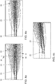
- FIGS. 4a to 4c The following are related to the FIGS. 4a to 4c described first and second partial light distributions of a high beam function, which can be generated by the headlamps 1 and 2 of the headlamp assembly generally.
- the diaphragms 10 and 11 are not in the beam path of the light emitted by the light source 7 and all light emitting diodes 13 of the second module are in the initial situation of FIG. 4a switched on:
- the total light distribution produced by the headlamp assembly is shown by a light-dark boundary on a road, being divided into two partial light distributions 23 and 24.
- the total light distribution of the high beam is regulated as a function of the speed of the vehicle.
- total light distribution can be set at a speed of, for example v ⁇ 90 km / h. Other speed limits from which the total light distribution is set are also possible.
- the total light distribution is composed of a first partial light distribution 23 generated by the first modules 3 and a second partial light distribution 24 generated by the second modules 4.
- the second partial light distribution 24 emerges beyond the light-dark boundary of the first partial light distribution 23.
- the area in front of the vehicle 22 is divided into a vehicle-related area 30 and a vehicle-distant area 31.
- the light-dark boundary of the total light distribution is generated by the first partial light distribution 23.
- the light-dark boundary is generated by the second partial light distribution 24.
- the first partial light distribution 23 in the vicinity of the vehicle 22 is wider than the second partial light distribution 24, the first partial light distribution 23 ensures a wide illumination of the traveled lane in the vehicle-proximate area 30.
- the second partial light distribution 24 generates a light-dark boundary in the vehicle-distant region 31 which is wider than the light-dark boundary of the first partial light distribution 23.
- the width of the light-dark boundary of the second partial light distribution 24 is of the width the area occupied by light emitting diodes 13 dependent.
- the second partial light distribution 24 has a broader cut-off line in the vehicle-distant area 31, it can be ensured that the driver of the vehicle 22 can already recognize dangers on or next to the road from a long distance. As a result, any necessary reactions can be initiated earlier.
- the second partial light distribution 24 generated by the second module 4 of the left headlamp 1 is further subdivided into a plurality of partial areas 25 to 29.
- the brightness of the subregions 25 to 29 decreases from the inside to the outside.
- the outermost subregion 25 accordingly has the lowest brightness of the subregions 25 to 29.
- the second partial light distribution 24 generated by the second module 4 of the right headlamp 2 is likewise subdivided into a plurality of partial areas 25 to 28.
- the innermost rows 55 and 56 of LEDs 13 are not turned on.
- the first partial light distribution 23 has a region 33 which is not illuminated by the second partial light distribution 24.
- This area 33 is located directly in front of the vehicle 22. This ensures that this area 33 is also sufficiently illuminated.
- the superposition of the first 23 and the second partial light distribution 24 generates a high beam, which provides a brighter light in the area in which the luminous intensities of both light distributions 23 and 24 add up, while areas using only one of the two light distributions 23 or 24 are not lit, also illuminated.
- the combination of the first 3 and the second module 4 thus leads overall to a brighter overall light distribution with wider illumination.
- total light distribution represents a high beam function at a speed of, for example v ⁇ 90 km / h.
- the first 23 and the second partial light distribution 24 are constructed in principle, as in FIG. 4a is shown.
- the headlight range is mainly regulated by the second partial light distribution 24.
- the first partial light distribution 23 changes compared to the first partial light distribution 23, as in FIG. 4a not shown.
- Figure 4c is the total light distribution when driving around a left turn shown.
- the curve is detected and the first partial light distribution 23 is also led to the left by pivoting the first modules to the left.
- the second partial light distribution 24 is thereby "pivoted" to the left, that increased light emitting diodes of the second module 4 of the left headlamp 2 are turned on.
- the outer rows 61 and 62 of LEDs of the left second module 4 are turned on, which now produce the outermost portions 25 and 26 of the second module 4 of the left headlight 1 generated part of the second partial light distribution 24.
- the innermost rows 55 and 56 of the left second module 4 are turned off.
- the part of the second partial light distribution 24 generated by the second module 4 of the right-hand headlight 2 is reduced overall in its brightness and width by driving corresponding rows of light-emitting diodes 13.
- the driver has the impression that the second partial light distribution 24 would be pivoted to the left as well as the first partial light distribution.
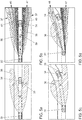
- FIGS. 5a, 5c and 5e For reasons of clarity, the masked long duration light produced by the first modules 3 is shown.
- FIGS. 5b, 5d and 5f show the superposition of the first partial light distribution 36 and the second partial light distribution 37 to a total light distribution, which can be produced by the method according to the invention:
- the starting point is a total light distribution as in FIG. 4a is shown.
- a preceding road user 34 is detected by the camera 18.
- the way in which the oncoming traffic participant is detected for example, in the DE 10 2009 054 227 A1 whose contents are incorporated by reference into the present application.
- the diaphragms 10 and 11 are then pushed into the beam path of the light emitted by the light source 7 of the first module 3 in such a way that on the roadway in the FIG. 5a shown first partial light distribution 36 is formed.
- first partial light distribution 36 has in the area M a headlight range, which is controlled so that it is at least less than the distance to the detected road user 34.
- a side area S 1 is formed, in which the headlight range is greater than the headlight range in the area M of the first partial light distribution 36. Beside the road user 34 is thus waivegesuitedt to the driver of Vehicle 22 to provide better illumination of the traffic area in front of the vehicle 22.
- the headlight range in the side area S 1 for example, the headlight range in a conventional high beam function correspond.
- a side area S 2 is formed, which also has a wider headlight range than the headlight range in the central region M.
- the headlight range of the side area S 2 corresponds to the headlight range of a conventional high beam function, so that the total light distribution corresponds to a conventional high beam in which, in the light distribution, an area at the detected road user 34 and in the direction of travel in front of the road user 22 is cut out.
- FIG. 5b a superposition of the second partial light distribution 37 generated by the second modules 4 with the first partial light distribution 36 is shown.
- the second partial light distribution 37 has two partial light beams 46 and 47, wherein a light beam 46 from the second module 4 of the left headlamp 1 and a light beam 47 from the second module 4 of the right headlamp 2 is generated.
- the left light beam 46 radiates on the left and the right light beam 47 passes right on the detected road user 34.
- the brightnesses of the first partial light distribution 36 and the second partial light distribution 37 add up in the two side regions S 1 and S 2 , while in the middle region M, only the first partial light distribution 36 provides illumination.
- the left light beam 46 of the second partial light distribution 37 is divided into subregions 42 to 45.
- the subregion 42 of the rows 58 and 59 and the subregions 43 to 45 corresponding to the rows 60 to 62 of light emitting diodes 13 of the left second module 4 are generated.
- the right light beam 47 is divided into the subregions 42, 44 and 45.
- the same reference numerals for the subregions of the left-hand 46 and right-hand light beams 47 mean the same brightnesses.
- the subregion 42 is generated by the rows 59 and 60 and the subregions 44 and 45 correspondingly by the rows 61 and 62 of light emitting diodes 13 of the right second module 4.
- the inner rows 55 to 57 of light emitting diodes 13 of the left second 4 and the inner rows 55 to 58 of light emitting diodes 13 of the right second module 4 are turned off.
- the central region M produces an edge 39 whose distance from the headlamp assembly depends on the beam width and the position of the diaphragms 10 and 11 in the beam path of the light emitted by the light source 7 of the first module 3. Furthermore, the side regions S 1 and S 2 , which are generated by the second partial light distribution 37, in the longitudinal direction LR to the vehicle 22 also produce two edges 40 and 41 whose distance to each other in the transverse direction QR to the vehicle 22 depends on the width of the detected vehicle 34. By the edges 39, 40 and 41, a light-free corridor 38 is formed, in which the detected vehicle 34 is located.
- FIG. 5b Compared to the sole first partial light distribution 36 off FIG. 5a , which generally corresponds to the total light distribution of the prior art masked longsight described in the prior art, it will be seen that the total light distribution consisting of the first 36 and second partial light distributions 37 FIG. 5b is not only brighter by adding the brightnesses of both partial light distributions 36 and 37, but also by the second partial light distribution 37 has a broader lighting range and the light-free corridor 38 can be very closely brought to the detected road users 34.
- the total light distribution consisting of the two partial light distributions 36 and 37 thus has overall a larger and further light field and in some areas a higher brightness without dazzling the vehicle driver 34 ahead.
- a soft transition between the light box and non-illuminated field can also be created.
- FIG. 5c the first partial light distribution 36 is shown when driving through a left turn. It is clear that the light range of the side area S 2 is lowered so far that it substantially coincides with the light range of the central region M. This is due to the fact that the diaphragms 10 and 11 must be displaced in the beam path of the light emitted by the light source 7 of the left first module 3 such that the light-free corridor 38 can track the detected road user 34. The displacement leads from a certain position of the aperture 10 and 11 to light that would produce the side area S 2 in the first light distribution 36 is shaded. The side region S 2 can no longer be formed by the first partial light distribution, as a result of which this side region S 2 remains completely unlit.
- the second partial light distribution 37 is generally structured as in FIG FIG. 5b ,
- the rows 55 and 56 of light-emitting diodes 13 which are illuminated in FIG FIG. 5b the inner portions 42 and 43 of the light beam 46 have generated turned off, so that the left light beam 46 now has a smaller width and only of the rows 57, 58 and 59, wherein the rows 58 and 59 emit light of the same luminance generated becomes.
- the right light beam 47 remains unchanged.
- the distance 35 between side area S 1 and detected road user 34 can be drastically reduced in this way, so that the light-free corridor 38 reaches up to the detected road user 34.
- the first partial light distribution 36 is shown when driving through a tight bend. It no longer differs from the first partial light distribution 36 in a normal curve, as in FIG. 5c shown.
- the distance 35 between the detected road user 34 and the side area S 1 is even greater than in FIG. 5b ,
- FIG. 5f In turn, an overall light distribution is shown, which is produced by the superimposition of the first 36 and the second partial light distribution 37.
- the LEDs 13 of the second module 4 of the left headlamp 2 are driven so that the left light beam 46 is divided into two partial light beams 48 and 49. This is done by turning off the rows 58 and 59 of light emitting diodes 13 which originally produced the subregions 42 and 43 of the left light beam 46. For this purpose, the subregions 42 and 43 are generated by the rows 56 and 57 of light emitting diodes 13. In addition, the innermost row 55 of LEDs 13 is turned on, so that an additional portion 50 is generated. This exudes the Partial light beam 49 right past the leading road user 34, and no longer as originally left on the leading road user 34 over. As a result, the right-hand light beam 47 and the partial-light beam 49 of the left-hand light beam 46 are superimposed, thus ensuring brighter illumination in the region to the right of the vehicle driver 34 ahead.
- the distance 35 between side area S 1 and detected road user 34 can be drastically reduced in this way.
- Subregions 45 and 44 are generated unchanged by the same rows 61 and 62 of light emitting diodes 13, as in FIG. 5d shown. As a result, the second partial light beam 48 is guided past the preceding vehicle on the left.
- FIGS. 5c, 5d . 5e and 5f is exemplified a ride through a left turn.
- the first 36 and the second partial light distribution 37 are generated in the same way only by mirrored driving of the first 3 and second module 4.
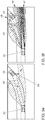
- FIGS. 6a to 6f are in the same way as in the FIGS. 5a to 5f first explained the first partial light distribution 36 alone in a traffic situation with an oncoming vehicle.
- a perspective view for clarifying the conclusion of the partial light distributions 36 and 37 by different positions of the first 3 and second modules 4 is shown.
- the partial light distributions 36 and 37 are shown schematically as they can be seen on a screen which is placed in front of the vehicle 22 at a certain distance.
- FIGS. 4a to 4c and 5b are shown schematically as they can be seen on a screen which is placed in front of the vehicle 22 at a certain distance.
- the headlight ranges of the second partial light distribution 37 are generally wider than the headlight ranges of the first partial light distribution 36 Figures 6b, 6d and 6f the second partial light distribution 37 is represented by a lower line density in the hatching.
- the partial light distributions 36 and 37 are regulated in the case of an oncoming traffic participant 53, as in the case of the preceding road user 34, when cornering.
- the starting point of the method according to the invention is again an overall light distribution of the high-beam function as shown in FIG. 4a is shown.
- an oncoming traffic participant 53 is detected by the camera 18.
- the diaphragms 10 and 11 are introduced into the beam path of the light emitted by the light source 7 of the first module 3 in such a way that in the light distribution a recess 54, as shown in FIG FIG. 6a shown forms.
- the recess 54 is placed where the oncoming road user 53 is located. On the road, this leads to the formation of the central region M and the two side regions S 1 and S 2 .
- the light emitting diodes 13 of the second module 4 are controlled by the control device 14 in such a way that the rows 55 and 56 of light emitting diodes 13, which are arranged at the innermost position in the second modules 4, are switched off.
- the number of rows that are turned off depends on the width and distance of the oncoming traffic participant 53.
- a recess in the second partial light distribution is generated at the same point as in the first partial light distribution.
- the superimposed partial light distribution 36 and 37 are in FIG. 6b shown. It becomes particularly clear that the second partial light distribution 37 also provides illumination in the outer and inner regions in which the first partial light distribution 36 does not provide illumination, while the first partial light distribution 36 illuminates there where the second partial light distribution 37 does not illuminate.
- the second partial light distribution 37 provides, in particular, no illumination in advance 63 of the vehicle 22.
- the light-free corridor 38 is generated on the road, in which the oncoming vehicle 53 moves.
- the distance of the vehicle 22 to the oncoming traffic participant 53 decreases. From a certain distance, the direction of travel 51 of the vehicle 22 and the connection line 52 are from the vehicle 22 to the oncoming vehicle 53 an angle ⁇ , which increases with decreasing distance.
- FIG. 6c an adaptation of the recess 54 to the oncoming traffic participant in the first partial light distribution 36 is shown.
- the apertures 10 and 11 of the first modules 3 are shifted vertically to the left and horizontally downwards. This results in an offset to the left and the distance of the oncoming vehicle 53 offset recess in the first partial light distribution 36.
- only the aperture 10 can be moved vertically to the left, while simultaneously adapted to adjust the beam width, the first module 3 about a horizontal axis becomes.
- FIG. 6d shows the superimposed first 36 and second partial light distributions 37.
- the second modules 4 are driven such that the light emitting diodes 13, which were previously turned off to produce the recess in the second partial light distribution 37, at least partially turned on, while other light emitting diodes 13, the were previously turned on to generate the side area S 2 , at least partially turned off.
- the LEDs 13 are turned on or off, that forms a new, offset to the left recess 54 in the second partial light distribution 37.
- the luminous range of the first partial light distribution in the side region S 2 must be lowered at a certain angle ⁇ such that it coincides with the luminous range of the first partial light distribution in the middle region M. This is FIG. 6e shown. This happens when a maximum displacement position of the aperture 10 and 11 of the left first module 3 is reached.
- FIG. 6c It will be seen that at a certain angle ⁇ in the side region S 2, the first partial light distribution 36 no longer contributes to the total light distribution.
- the light-emitting diodes 13 which provide the sole illumination of the side region S 2 must then be switched off.
- first and second partial light distributions are then combinations of the first and second partial light distributions of FIGS. 5b . d and f and 6b, d and f.
- FIG DE 10 2009 054 227 A1 A detailed headlight range control as a function of the horizontal angle ⁇ for the first partial light distribution 36 is shown in FIG DE 10 2009 054 227 A1 whose contents are incorporated by reference into the present application.
- a low-beam function can also be provided.
Landscapes
- Engineering & Computer Science (AREA)
- General Engineering & Computer Science (AREA)
- Physics & Mathematics (AREA)
- Microelectronics & Electronic Packaging (AREA)
- Optics & Photonics (AREA)
- Mechanical Engineering (AREA)
- Mathematical Physics (AREA)
- Lighting Device Outwards From Vehicle And Optical Signal (AREA)
- Non-Portable Lighting Devices Or Systems Thereof (AREA)
Description
Die vorliegende Erfindung betrifft ein Verfahren zum Steuern einer Scheinwerferanordnung für ein Fahrzeug mit den Merkmalen vom Oberbegriff des Anspruchs 1.The present invention relates to a method for controlling a headlamp assembly for a vehicle having the features of the preamble of
Die Scheinwerfer eines Fahrzeugs haben die Aufgabe, bei schlechten Sichtverhältnissen, insbesondere bei Dunkelheit, die Umgebung in Fahrtrichtung von dem Fahrzeug, insbesondere die Fahrbahn, auszuleuchten. Zusätzlich dienen die Scheinwerfer als Erkennungsmerkmal für andere Verkehrsteilnehmer.The headlights of a vehicle have the task, in poor visibility, especially in the dark, the environment in the direction of the vehicle, in particular the road, illuminate. In addition, the headlights serve as a distinguishing feature for other road users.
Es ist bekannt, für die Lichtemission in Fahrtrichtung Scheinwerfer vorzusehen, welche eine Abblendlichtfunktion und eine Fernlichtfunktion bereitstellen können. Dabei sorgt die Fernlichtfunktion für eine sehr umfassende Ausleuchtung der Umgebung. Sie besitzt jedoch den Nachteil, dass andere Verkehrsteilnehmer, insbesondere die Fahrer vorausfahrender und entgegenkommender Fahrzeuge, geblendet werden. Mit dem Abblendlicht kann hingegen eine Lichtverteilung erzeugt werden, welche andere Verkehrsteilnehmer nicht blendet. Die Ausleuchtung der Umgebung ist jedoch sehr viel geringer als bei der Fernlichtfunktion. Aufgrund der mittlerweile sehr hohen Verkehrsdichten kann die Fernlichtfunktion nur noch sehr selten eingesetzt werden. Es besteht daher ein Bedürfnis, Scheinwerferanordnungen bereitzustellen, die eine bessere Ausleuchtung als die herkömmliche Abblendlichtfunktion bereitstellen, die jedoch nicht wie die Fernlichtfunktion andere Verkehrsteilnehmer blenden.It is known to provide for the light emission in the direction of travel headlights, which can provide a low beam function and a high beam function. The high beam function ensures a very comprehensive illumination of the environment. However, it has the disadvantage that other road users, especially the drivers of preceding and oncoming vehicles are dazzled. With the dipped beam, however, a light distribution can be generated, which does not dazzle other road users. However, the illumination of the environment is much lower than in the high beam function. Due to the now very high traffic densities, the high beam function can be used only very rarely. There is therefore a need to provide headlamp assemblies which provide better illumination than the conventional low beam function, but which do not dazzle other road users like the high beam function.
Dazu ist aus den Druckschriften
Weiterhin bekannt sind sogenannte Matrixscheinwerfer, welche in einer Matrix angeordnete Lichtquellen aufweisen. Bei Matrixscheinwerfern werden unterschiedliche Lichtverteilungen durch das Ansteuern unterschiedlicher Lichtquellen in der Matrix erreicht. Die Lichtquellen bei Matrixscheinwerfern sind in der Regel Leuchtdioden. Die Technologie von Matrixscheinwerfern beruht daher im Allgemeinen auf rein elektronischen Vorgängen. Beispiele zu Matrixscheinwerfern und Verfahren zu deren Steuerung sind aus den Druckschriften
Der Druckschrift
Schließlich ist aus der
Der vorliegenden Erfindung liegt die Aufgabe zugrunde, ein Verfahren und eine Vorrichtung bereitzustellen, durch welche eine umfassende Beleuchtung der Fahrzeugumgebung bereitgestellt werden kann.It is an object of the present invention to provide a method and apparatus by which comprehensive illumination of the vehicle environment can be provided.
Diese Aufgabe wird durch ein Verfahren nach Anspruch 1 und eine Scheinwerferanordnung nach Anspruch 8 gelöst. Vorteilhafte Ausgestaltungen und Weiterbildungen sind Gegenstände der abhängigen Ansprüche.This object is achieved by a method according to
Bei dem erfindungsgemäßen Verfahren wird eine erste Teillichtverteilung einer Lichtfunktion von den ersten Modulen durch Verändern einer Position des zumindest einen bewegbaren Elemente erzeugt, eine zweite Teillichtverteilung der gleichen Lichtfunktion von den zweiten Modulen durch Ansteuern einzelner Lichtquellen oder Gruppen von Lichtquellen der Vielzahl von Lichtquellen erzeugt, und die Gesamtlichtverteilung der Lichtfunktion wird dadurch erzeugt, dass die erste Teillichtverteilung und die zweite Teillichtverteilung überlagert werden. Je nach Ausgestaltung des bewegbaren Elementes kann mit Verändern einer Position des zumindest einen bewegbaren Elementes auch eine Drehung um eine Achse des bewegbaren Elementes gemeint sein.In the method according to the invention, a first partial light distribution of a light function of the first modules by changing a position of the at least one movable Produces elements, generates a second partial light distribution of the same light function of the second modules by driving individual light sources or groups of light sources of the plurality of light sources, and the total light distribution of the light function is generated by the first partial light distribution and the second partial light distribution are superimposed. Depending on the configuration of the movable element may be meant by changing a position of the at least one movable element and a rotation about an axis of the movable element.
Das Verfahren hat den Vorteil, dass die Lichtfunktion durch eine Kombination einer durch ein mechanisch betriebenes Modul erzeugten Teillichtverteilung und einer durch ein elektronisch betriebenes Modul erzeugten Teillichtverteilung erzeugt wird. Dadurch können die Vorteile beider technischer Eigenschaften ausgenutzt werden. Insbesondere wird durch die Kombination der beiden Module die streifenartige Lichtverteilung, welche beispielsweise durch eine Leuchtdioden-Matrix entsteht, durch die Überlagerung der Lichtverteilung des mechanisch betriebenen Moduls geglättet. Dadurch wird eine hohe Homogenität der Lichtverteilung erreicht.The method has the advantage that the light function is generated by a combination of a partial light distribution generated by a mechanically operated module and a partial light distribution generated by an electronically operated module. As a result, the advantages of both technical properties can be exploited. In particular, by the combination of the two modules, the strip-like light distribution, which is formed for example by a light-emitting diode matrix, smoothed by the superposition of the light distribution of the mechanically operated module. As a result, a high homogeneity of the light distribution is achieved.
In einer Eigenschaft der Erfindung wird zumindest ein Verkehrsteilnehmer in Richtung der Lichtemission der Scheinwerferanordnung erfasst. Die erste Teillichtverteilung wird dann derart geregelt, dass sie einen Mittelbereich mit einer Leuchtweite aufweist, die geringer als der Abstand zu dem erfassten Verkehrsteilnehmer ist, und zwei Seitenbereiche, welche beidseitig neben dem Mittelbereich erzeugt werden, mit Leuchtweiten aufweist, die größer als der Abstand zu dem erfassten Verkehrsteilnehmer sind. Die zweite Teillichtverteilung wird derart geregelt, dass sie nur in den Seitenbereichen der ersten Teillichtverteilung Leuchtweiten aufweist, die größer als der Abstand zu dem erfassten Verkehrsteilnehmer sind. Dies hat insbesondere den Vorteil, dass andere Verkehrsteilnehmer aus der Gesamtlichtverteilung ausmaskiert werden und somit nicht geblendet werden. Dies stellt insbesondere die bereits erwähnte maskierte Dauerfernlichtfunktion bereit.In one feature of the invention, at least one road user is detected in the direction of the light emission of the headlamp assembly. The first partial light distribution is then controlled such that it has a central area with a luminous beam that is less than the distance to the detected road user, and two side areas, which are generated on both sides next to the central area, with headlights that are greater than the distance to the registered road user. The second partial light distribution is regulated in such a way that it has headlight ranges which are greater than the distance to the detected road user only in the side areas of the first partial light distribution. This has the particular advantage that other road users are masked out of the total light distribution and thus not dazzled. In particular, this provides the aforementioned masked long distance function.
Betrachtet man die Hell-Dunkel-Grenze des maskierten Dauerfernlichts auf einem senkrecht angeordneten Messschirm, wird insbesondere vor dem erfassten Verkehrsteilnehmer eine horizontale Hell-Dunkel-Grenze gebildet und neben dem erfassten Verkehrsteilnehmer wird eine senkrechte Hell-Dunkel-Grenze gebildet, welche der höheren Leuchtweite in dem Bereich neben dem erfassten Verkehrsteilnehmer entspricht. Die Leuchtweite im Mittelbereich, welche bei der zweiten Gesamtlichtverteilung insbesondere bis zum erfassten Verkehrsteilnehmer reicht, wird bevorzugt durch eine bereits vorhandene Leuchtweitenregulierung geregelt. Da die Hell-Dunkel-Grenze im Mittelbereich lediglich von dem ersten Modul bereitgestellt wird, kann diese Leuchtweitenregulierung durch ein Schwenken lediglich des ersten Moduls erreicht werden.If the light-dark boundary of the masked long-distance light is viewed on a vertically arranged measuring screen, a horizontal light-dark boundary is formed in front of the detected road user and a vertical light-dark boundary is formed next to the detected road user and the higher light range in the area next to the detected road user. The headlight range in the central region, which in the second overall light distribution extends in particular to the detected road user, is preferably regulated by an already existing headlight range control. Since the bright-dark border in the middle area is provided only by the first module, can this headlamp leveling can be achieved by pivoting only the first module.
Unter dem Begriff Leuchtweite wird im Sinne der Erfindung eine winkelabhängige Entfernung auf der Straße verstanden, bei der die Lichtintensität einen Grenzwert unterschreitet. In Entfernungen, die über die Leuchtweite hinausgehen, ist die Lichtintensität insbesondere so gering, dass andere Verkehrsteilnehmer nicht mehr geblendet werden. Der Winkel ist insbesondere ein Horizontalwinkel, der von einer Längsachse durch einen Scheinwerfer oder eine Scheinwerferanordnung und einer Verbindungslinie von einem Punkt auf der Hell-Dunkel-Grenze und dem Schnittpunkt der Längsachse mit einer Querachse, welche durch den Scheinwerfer bzw. die Scheinwerferanordnung führt, gebildet wird.For the purposes of the invention, the term " headlight range" is understood to mean an angle-dependent distance on the road in which the light intensity falls below a limit value. At distances that extend beyond the beam range, the light intensity is particularly low so that other road users are no longer dazzled. In particular, the angle is a horizontal angle formed by a longitudinal axis through a headlamp or headlamp assembly and a connecting line from a point on the cut-off line and the intersection of the longitudinal axis with a transverse axis passing through the headlamp or headlamp assembly becomes.
In einer Ausgestaltuung wird die Hell-Dunkel-Grenze der Gesamtlichtverteilung in einen fahrzeugnahen und einen fahrzeugfernen Bereich aufgeteilt, wobei der fahrzeugnahe Bereich von der ersten Teillichtverteilung und der fahrzeugferne Bereich von der zweiten Teillichtverteilung erzeugt wird. Dies bewirkt, dass die unterschiedlichen Eigenschaften der ersten und zweiten Teillichtverteilungen zum Vorteil für die Gesamtlichtverteilung verwendet werden können. So kann eine Verbreiterung der Hell-Dunkel-Grenze der Gesamtlichtverteilung nach vorne erreicht werden. Außerdem kann die Hell-Dunkel-Grenze der ersten Teillichtverteilung dort breiter sein, wo die zweite Teillichtverteilung aufgrund technischer Grenzen des elektronischen Moduls keine ausreichend breite Hell-Dunkel-Grenze erzeugen kann. Die zweite Teillichtverteilung hingegen kann dort breiter sein, wo sich die Breite der Hell-Dunkel-Grenze der ersten Teillichtverteilung aufgrund technischer Grenzen des mechanisch betriebenen Moduls bereits wieder verschmälert oder sich nicht weiter verbreitert. Für den fahrzeugfernen Bereich bedeutet dies also eine breitere Gesamtlichtverteilung, die eine bessere Ausleuchtung in den Seitenbereichen bereitstellt.In one embodiment, the light-dark boundary of the total light distribution is divided into a vehicle-related and a vehicle-distant region, wherein the vehicle-near region is generated by the first partial light distribution and the vehicle-distant region by the second partial light distribution. This has the effect that the different properties of the first and second partial light distributions can be used to advantage for the overall light distribution. Thus, a widening of the cut-off line of the total light distribution forward can be achieved. Moreover, the light-dark boundary of the first partial light distribution can be wider where the second partial light distribution can not produce a sufficiently broad cut-off line due to technical limitations of the electronic module. By contrast, the second partial light distribution can be wider where the width of the light-dark boundary of the first partial light distribution already narrows or does not widen further due to technical limitations of the mechanically operated module. For the vehicle-distant area, this therefore means a broader overall light distribution, which provides better illumination in the side areas.
In einer weiteren Ausgestaltung wird durch den Mittelbereich und die Seitenbereiche in der Gesamtlichtverteilung ein lichtfreier Korridor gebildet, wobei der lichtfreie Korridor eine von dem Mittelbereich in Querrichtung zum Fahrzeug erzeugte Kante und zwei von den Seitenbereichen in Längsrichtung zum Fahrzeug erzeugte Kanten aufweist, wobei die von den Seitenbereichen erzeugten Kanten im Wesentlichen von der zweiten Teillichtverteilung erzeugt werden und der Abstand in Querrichtung zwischen den von den Seitenbereichen erzeugten Kanten von der Breite des erfassten Verkehrsteilnehmers abhängt. Werden die von den Seitenbereichen erzeugten Kanten im Wesentlichen von der zweiten Teillichtverteilung erzeugt, so hat dies den Vorteil, dass der lichtfreie Korridor nah an den erfassten Verkehrsteilnehmer herangeführt werden kann. Dies ist möglich, da durch die Matrix von Lichtquellen ausgewählte Reihen von Lichtquellen die Seitenbereiche erzeugen, welche wiederum die Kanten der Seitenbereiche erzeugen. Dadurch ist eine im Wesentlichen lineare Lichtabstrahlung möglich, die die Kanten der Seitenbereiche bis auf wenige cm an den erfassten Verkehrsteilnehmer heranführen kann. Dadurch entstehen bis auf den lichtfreien Korridor keine großen Lücken in der Gesamtlichtverteilung.In a further embodiment, a light-free corridor is formed by the central area and the side areas in the total light distribution, the light-free corridor having an edge created from the central area transverse to the vehicle and two edges longitudinally from the vehicle to the vehicle Side edges are generated substantially by the second partial light distribution and the distance in the transverse direction between the edges generated by the side regions depends on the width of the detected road user. If the edges generated by the side regions are generated essentially by the second partial light distribution, this has the advantage that the light-free corridor can be brought close to the detected road user. This is possible because rows of light sources selected by the matrix of light sources generate the side areas, which in turn are the edges of the side areas produce. As a result, a substantially linear light emission is possible, which can bring the edges of the side areas up to a few cm to the detected road users. As a result, there are no major gaps in the overall light distribution except for the light-free corridor.
Insbesondere wird in Abhängigkeit von dem horizontalen Winkel zwischen der Fahrtrichtung des Fahrzeugs und der Verbindungslinie von dem Fahrzeug zu dem erfassten Verkehrsteilnehmer die Leuchtweite der ersten Teillichtverteilung in zumindest einem Seitenbereich derart abgesenkt, dass ab einem bestimmten Winkel der Seitenbereich nur von der zweiten Teillichtverteilung erzeugt wird. In der Regel ist das Absenken der Leuchtweite in zumindest einem Bereich begrenzt durch die technischen Grenzen mechanisch gesteuerter Module und durch die optischen Eigenschaften von bewegbaren Elementen, die in Strahlengänge eingeführt werden. Die Veränderung der Position von bewegbaren Elementen in einem Strahlengang führt nämlich insbesondere in weiter Entfernung zu erheblichen Veränderungen in der Lichtverteilung. Vor allem in einer Extremstellung der bewegbaren Elemente, also beispielsweise ganz außen im ersten Modul, führt dies dazu, dass in einem der beiden Seitenbereichen oder in beiden Seitenbereichen keine Ausleuchtung aufgrund der ersten Teillichtverteilung mehr möglich ist. Um zu vermeiden, dass diese Seitenbereiche unbeleuchtet bleiben, kann vorteilhafterweise die zweite Teillichtverteilung dort eine Ausleuchtung bereitstellen. Dies wiederum gewährleistet eine umfassendere Ausleuchtung der Umgebung.In particular, depending on the horizontal angle between the direction of travel of the vehicle and the connecting line from the vehicle to the detected road user, the range of the first partial light distribution in at least one side area is lowered in such a way that from a certain angle the side area is generated only by the second partial light distribution. In general, the lowering of the beam range is limited in at least one area by the technical limits of mechanically controlled modules and by the optical properties of movable elements that are introduced into beam paths. Namely, the change of the position of movable elements in a beam path leads to significant changes in the light distribution, especially in the far distance. Especially in an extreme position of the movable elements, that is, for example, completely outside in the first module, this leads to the fact that in one of the two side areas or in both side areas no illumination due to the first partial light distribution is possible. In order to avoid that these side areas remain unlit, advantageously, the second partial light distribution can provide illumination there. This in turn ensures a more complete illumination of the environment.
Bevorzugt wird die zweite Teillichtverteilung von zumindest zwei Lichtstrahlen erzeugt, wobei zumindest einer dieser beiden Lichtstrahlen in Abhängigkeit von dem horizontalen Winkel zwischen der Fahrtrichtung des Fahrzeugs und der Verbindungslinie von dem Fahrzeug zu dem erfassten Verkehrsteilnehmer in zwei Teillichtstrahlen unterteilt wird, so dass ein Teillichtstrahl den einen Seitenbereich alleine erzeugt und der andere Teillichtstrahl den anderen Seitenbereich gemeinsam zumindest mit dem anderen Lichtstrahl der zweiten Teillichtverteilung erzeugt. Dabei wird der eine Lichtstrahl insbesondere von dem zweiten Modul des rechten Scheinwerfers und der andere Lichtstrahl von dem zweiten Modul des linken Scheinwerfers erzeugt. Dadurch kann vorteilhafterweise gewährleistet werden, dass andere Verkehrsteilnehmer auch in engen Kurven oder bei geringen Abständen zu entgegenkommenden Verkehrsteilnehmer nicht geblendet werden.Preferably, the second partial light distribution of at least two light beams is generated, wherein at least one of these two light beams is divided into two partial light beams depending on the horizontal angle between the direction of travel of the vehicle and the connecting line from the vehicle to the detected road user, so that a partial light beam the one Generated side area alone and the other partial light beam generated the other side area together at least with the other light beam of the second partial light distribution. In this case, the one light beam is generated in particular by the second module of the right headlamp and the other light beam by the second module of the left headlamp. This can advantageously be ensured that other road users are not dazzled even in tight bends or at short distances to oncoming traffic participants.
Bevorzugt wird die zweite Teillichtverteilung in den Seitenbereichen in mehrere Teilbereiche aufgeteilt, wobei die Helligkeit vom innersten Teilbereich zum äußersten Teilbereich abfällt. Dadurch wird vorteilhafterweise vermieden, dass zwischen dem Bereich der Lichtverteilung und dem nicht beleuchteten Umfeld die Helligkeit plötzlich abfällt. Ein weicher Übergang zwischen Lichtverteilung und Umfeld wird ermöglicht.
Bevorzugt ist die Lichtfunktion eine Fernlichtfunktion. Dies ist deswegen vorteilhaft, da dann auch auf Strecken, die schlecht beleuchtet sind, wie z.B. Autobahnen und Landstraßen, auf denen eine Abblendlichtfunktion keine ausreichende Ausleuchtung bietet, eine umfassende Beleuchtung der Umgebung bereitgestellt werden kann.
Des Weiteren wird eine Scheinwerferanordnung für ein Fahrzeug bereitgestellt. Die erfindungsgemäße Scheinwerferanordnung weist zumindest zwei beabstandeten Scheinwerfern auf, mittels welchen eine Gesamtlichtverteilung erzeugbar ist, wobei beide Scheinwerfer jeweils zumindest ein erstes und ein zweites Modul umfassen, welche separat voneinander angeordnet sind. Dabei umfasst das erstes Modul jeweils zumindest eine Lichtquelle und zumindest ein bewegbares Element, welches in den Strahlengang des von der Lichtquelle emittierten Lichts bringbar ist. Das zweite Modul umfasst jeweils eine Vielzahl von in einer Matrix angeordneten Lichtquellen. Ferner weist die erfindungsgemäße Scheinwerferanordnung eine Steuervorrichtung auf, mit welcher die ersten Module so ansteuerbar sind, dass durch Verändern einer Position des zumindest einen bewegbaren Elementes eine erste Teillichtverteilung einer Lichtfunktion erzeugbar ist, und mit welcher das zweite Modul so ansteuerbar ist, dass durch Ansteuern einzelner Lichtquellen oder Gruppen von Lichtquellen der Vielzahl von Lichtquellen eine zweite Teillichtverteilung der gleichen Lichtfunktion erzeugbar ist. Mit der Steuervorrichtung sind weiterhin die Scheinwerfer so ansteuerbar, dass durch Überlagern der ersten und der zweiten Teillichtverteilung die Gesamtlichtverteilung erzeugbar ist.Preferably, the second partial light distribution in the side areas is divided into a plurality of partial areas, wherein the brightness drops from the innermost partial area to the outermost partial area. This advantageously avoids that between the area of the light distribution and In the non-illuminated environment the brightness suddenly drops. A smooth transition between light distribution and environment is made possible.
Preferably, the light function is a high beam function. This is advantageous because then also on routes that are poorly lit, such as highways and highways on which a low beam function does not provide sufficient illumination, a comprehensive lighting of the environment can be provided.
Furthermore, a headlight assembly for a vehicle is provided. The headlight assembly according to the invention has at least two spaced headlamps, by means of which an overall light distribution can be generated, wherein both headlamps each comprise at least a first and a second module, which are arranged separately from each other. In this case, the first module in each case comprises at least one light source and at least one movable element, which can be brought into the beam path of the light emitted by the light source. The second module each comprises a plurality of light sources arranged in a matrix. Furthermore, the headlight assembly according to the invention has a control device with which the first modules are controlled so that by changing a position of the at least one movable element, a first partial light distribution of a light function can be generated, and with which the second module is so controlled that by driving individual Light sources or groups of light sources of the plurality of light sources, a second partial light distribution of the same light function can be generated. With the control device, the headlights are further controlled so that the total light distribution can be generated by superimposing the first and the second partial light distribution.
Die erfindungsgemäße Scheinwerferanordnung ist so ausgebildet, dass sie das erfindungsgemäße Verfahren vollständig ausführen kann.The headlight assembly according to the invention is designed so that it can perform the inventive method completely.
Dafür weist die Scheinwerferanordnung zusätzlich eine Einrichtung zum Erfassen von Verkehrsteilnehmern in Fahrtrichtung vor dem Fahrzeug auf. Die Steuervorrichtung ist dann auch mit der Einrichtung zum Erfassen gekoppelt, z.B. über eine zweite Steuervorrichtung.
Insbesondere sind die zumindest eine Lichtquelle des ersten Modul und/oder die Vielzahl von Lichtquellen des zweiten Moduls Leuchtdioden. Das bewegbare Element des ersten Moduls kann in ihrer Position veränderbare Blenden umfassen. Weiterhin kann das bewegbare Element auch eine Blendenwelle mit separaten Wellenabschnitten sein, wobei die separaten Wellenabschnitte unterschiedliche Brennlinien aufweisen. Dabei ist mit zumindest einer dieser Brennlinien die ersten Teillichtverteilung erzeugbar.For the headlamp assembly additionally has a device for detecting road users in the direction of travel in front of the vehicle. The control device is then also coupled to the device for detecting, for example via a second control device.
In particular, the at least one light source of the first module and / or the plurality of light sources of the second module are light-emitting diodes. The movable element of the first module may comprise variable aperture stops. Furthermore, the movable element may also be a diaphragm shaft with separate shaft sections, wherein the separate Shaft sections have different focal lines. In this case, the first partial light distribution can be generated with at least one of these focal lines.
Im Folgenden wird die Erfindung anhand von Ausführungsbeispielen mit Bezug zu den Zeichnungen erläutert.
Figur 1- zeigt den schematischen Aufbau eines Ausführungsbeispiels eines Scheinwerfers der erfindungsgemäßen Scheinwerferanordnung,
- Figur 2a
- zeigt schematisch ein Ausführungsbeispiel des ersten Moduls eines Scheinwerfers,
- Figur 2b
- zeigt schematisch ein Ausführungsbeispiel des zweiten Moduls eines Scheinwerfers,
Figur 3- zeigt schematisch ein Ausführungsbeispiel der erfindungsgemäßen Scheinwerferanordnung,
- Figuren 4a-c
- zeigen eine Überlagerung erster und zweiter Teillichtverteilungen einer Fernlichtfunktion ohne Blenden, die in den Strahlengang des Lichts eingebracht wurden, das von der Lichtquelle des ersten Moduls emittiert wurde, und zwar in verschiedenen Verkehrssituationen,
- Figuren 5a, c, e
- zeigen erste Teillichtverteilungen einer maskierten Dauerfernlichtfunktion in den in
Figuren 4a bis c gezeigten Fahrsituationen mit erfasstem vorausfahrenden Verkehrsteilnehmer, - Figuren 5b, d,
- f zeigen Lichtverteilungen bei einer Überlagerung der ersten und zweiten Teillichtverteilungen in denselben Fahrsituationen wie in
Figuren 5a, c unde mit erfasstem vorausfahrenden Verkehrsteilnehmer, - Figuren 6a, c, e
- zeigen erste Teillichtverteilungen einer maskierten Dauerfernlichtfunktion in den in
Figuren 4a bis c gezeigten Fahrsituationen betrachtet auf einem senkrecht angeordneten Messschirm mit erfasstem entgegenkommenden Verkehrsteilnehmer und - Figuren 6b, d, f
- zeigen Lichtverteilungen bei einer Überlagerung der ersten und zweiten Teillichtverteilungen in denselben Fahrsituationen, wie in
Figuren 6a, c und e gezeigt, mit erfasstem entgegenkommenden Verkehrsteilnehmer,
- FIG. 1
- shows the schematic structure of an embodiment of a headlamp of the headlamp assembly according to the invention,
- FIG. 2a
- shows schematically an embodiment of the first module of a headlamp,
- FIG. 2b
- shows schematically an embodiment of the second module of a headlamp,
- FIG. 3
- shows schematically an embodiment of the headlamp assembly according to the invention,
- FIGS. 4a-c
- show a superposition of first and second partial light distributions of a high-beam function without diaphragms, which were introduced into the beam path of the light emitted by the light source of the first module, in different traffic situations,
- FIGS. 5a, c, e
- First partial light distributions of a masked long distance function are shown in the in
FIGS. 4a to c shown driving situations with detected preceding road users, - FIGS. 5b, d,
- f show light distributions when the first and second partial light distributions are superimposed in the same driving situations as in FIG
FIGS. 5a, c ande with detected preceding road user, - FIGS. 6a, c, e
- First partial light distributions of a masked long distance function are shown in the in
FIGS. 4a to c shown driving situations considered on a vertically arranged screen with detected oncoming road users and - FIGS. 6b, d, f
- show light distributions with a superimposition of the first and second partial light distributions in the same driving situations, as in FIG
FIGS. 6a, c and e shown, with detected oncoming road users,
Die Scheinwerferanordnung, die allgemein in
In
In
In
Mit Bezug zur
Die Scheinwerfer 1, 2 sind jeweils mit einem Steuergerät 14 verbunden. Mittels der Steuergeräte 14 werden die Teillichtverteilungen der Scheinwerfer 1 und 2 gesteuert, welche überlagert eine Gesamtlichtverteilung ergeben.The
Die Steuergeräte 14 steuern eine Leuchtweitenregulierung für die Scheinwerfer 1 und 2, bei welcher die Scheinwerfer 1 und 2 um eine horizontale Achse mittels der Aktuatoren 16 schwenkbar sind. Ferner steuern die Steuergeräte 14 die Aktuatoren 15, mit denen die Scheinwerfer 1 und 2 um eine vertikale Achse schwenkbar sind. Mittels der Aktuatoren 15 kann die Lichtemissionsrichtung L des Scheinwerfers 1 bzw. des Scheinwerfers 2 in Richtung des Pfeils B1 geschwenkt werden. Die Aktuatoren 15 sind beispielsweise Teil eines bereits vorhandenen Kurvenlichts. Weiterhin sind auch die ersten Module 3 alleine mittels der Aktuatoren 16 um eine horizontale Achse schwenkbar, so dass sie in Richtung des Pfeils A (siehe
Weiterhin steuern die Steuergeräte 14 die vertikale und/oder horizontale Lage der Blenden 10 und 11 des ersten Moduls 3 für den rechten und linken Scheinwerfer 1, 2 mittels der Aktuatoren 17. Die Aktuatoren 17 umfassen einen Schrittmotor, dessen Welle sich um eine Drehachse dreht. Mit dieser Drehachse ist über ein radiales Verbindungselement ein Stift gekoppelt, der sich beim Betrieb des Schrittmotors auf einer Kreisbahn bewegt.Furthermore, the
Die Art und Weise, wie verschiedene erste Teillichtverteilungen durch die Bewegung der Blenden 10 und 11 erzeugt werden können, ist detailliert beispielsweise in der
Alternativ kann die erste Teillichtverteilung auch durch eine drehbare Blendenwelle erzeugt werden, welche mit zumindest einer Brennlinie zur Erzeugung der ersten Teillichtverteilung versehen ist. Die Drehachse ist dabei über ein Getriebe in unterschiedliche Drehstellungen bringbar und translatorisch im Strahlengang des von der ersten Lichtquelle 7 emittierten Lichts verschiebbar. Die Drehung wird dann über die Aktuatoren 14 und die translatorische Verschiebung über die Aktuatoren 15 ausgeführt. Eine solche Blendewelle ist beispielsweise in der
Im Folgenden werden mit Bezug zu den
Die von der Scheinwerferanordnung erzeugte Gesamtlichtverteilung ist anhand einer Hell-Dunkel-Grenze auf einer Straße gezeigt, wobei sie in zwei Teillichtverteilungen 23 und 24 aufgeteilt ist. Weiterhin wird die Gesamtlichtverteilung des Fernlichts in Abhängigkeit von der Geschwindigkeit des Fahrzeugs geregelt.The following are related to the
The total light distribution produced by the headlamp assembly is shown by a light-dark boundary on a road, being divided into two partial
Die in
Die Gesamtlichtverteilung setzt sich zusammen aus einer von den ersten Modulen 3 erzeugten ersten Teillichtverteilung 23 und einer von den zweiten Modulen 4 erzeugten zweiten Teillichtverteilung 24.The total light distribution is composed of a first partial
An der Grenze 32 tritt die zweite Teillichtverteilung 24 über die Hell-Dunkel-Grenze der ersten Teillichtverteilung 23 hinaus. Dadurch wird der Bereich vor dem Fahrzeug 22 in einen fahrzeugnahen 30 und einen fahrzeugfernen Bereich 31 aufgeteilt.At the
In dem fahrzeugnahen Bereich 30 wird die Hell-Dunkel-Grenze der Gesamtlichtverteilung von der ersten Teillichtverteilung 23 erzeugt. In dem fahrzeugfernen Bereich 31 wird die Hell-Dunkel-Grenze von der zweiten Teillichtverteilung 24 erzeugt.In the vehicle-
Da die erste Teillichtverteilung 23 in der Nähe des Fahrzeugs 22 breiter ist als die zweite Teillichtverteilung 24, gewährleistet die erste Teillichtverteilung 23 ein breite Ausleuchtung der befahrenen Fahrbahn im fahrzeugnahen Bereich 30. Die erste Teillichtverteilung 23 leuchtet den fahrzeugfernen Bereich 31 zwar noch aus, wird dort allerdings nicht mehr breiter.
Die zweite Teillichtverteilung 24 erzeugt in dem fahrzeugfernen Bereich 31 eine Hell-Dunkel-Grenze, welche breiter ist, als die Hell-Dunkel-Grenze der ersten Teillichtverteilung 23. Die Breite der Hell-Dunkel-Grenze der zweiten Teillichtverteilung 24 ist dabei von der Breite der mit Leuchtdioden 13 besetzten Fläche abhängig.Since the first partial
The second partial
Dadurch, dass die zweite Teillichtverteilung 24 eine breitere Hell-Dunkel-Grenze im fahrzeugfernen Bereich 31 aufweist, kann gewährleistet werden, dass der Fahrer des Fahrzeugs 22 Gefahren auf oder neben der Straße bereits aus einer weiten Entfernung erkennen kann. Dadurch können eventuell notwendige Reaktionen früher eingeleitet werden.Due to the fact that the second partial
Die von dem zweiten Modul 4 des linken Scheinwerfers 1 erzeugte zweite Teillichtverteilung 24 ist ferner in mehrere Teilbereiche 25 bis 29 unterteilt. Dabei wird der Teilbereich 25 von der Reihe 60 von Leuchtdioden 13, der Teilbereich 26 von der Reihe 59 von Leuchtdioden 13, der Teilbereich 27 von der Reihe 58 von Leuchtdioden 13, der Teilbereich 28 von der Reihe 57 von Leuchtdioden 13 und der Teilbereich 29 von den Reihen 56 und 55 von Leuchtdioden 13, erzeugt. Um einen plötzlichen Helligkeitsabfall zwischen der Gesamtlichtverteilung und der nicht ausgeleuchteten Umgebung zu vermeiden, fällt die Helligkeit der Teilbereiche 25 bis 29 von innen nach außen ab. Der äußerste Teilbereich 25 weist demnach die geringste Helligkeit der Teilbereiche 25 bis 29 auf. Dies kann dadurch realisiert werden, dass die für die unterschiedlichen Teilbereiche 25 bis 29 verantwortlichen Reihen von Leuchtdioden 13 unterschiedlich stark gedimmt werden. Es können auch die Reihen von Leuchtdioden 13, welche die Teilbereiche 27 bis 29 erzeugen mit gleicher Leuchtstärke betrieben werden, und lediglich die Reihen von Leuchtdioden 13, welche die Teilbereiche 25 und 26 erzeugen, gedimmt werden.The second partial
Die von dem zweiten Modul 4 des rechten Scheinwerfers 2 erzeugte zweite Teillichtverteilung 24 ist ebenso in mehrere Teilbereiche 25 bis 28 unterteilt. Dabei sind die innersten Reihen 55 und 56 von Leuchtdioden 13 nicht eingeschaltet.The second partial
Weiterhin weist die erste Teillichtverteilung 23 einen Bereich 33 auf, der von der zweiten Teillichtverteilung 24 nicht ausgeleuchtet wird. Dieser Bereich 33 befindet sich direkt vor dem Fahrzeug 22. Dadurch wird gewährleistet, dass auch dieser Bereich 33 ausreichend ausgeleuchtet ist.Furthermore, the first partial
Die Überlagerung der ersten 23 und der zweiten Teillichtverteilung 24 erzeugt ein Fernlicht, welches in dem Bereich, in dem sich die Leuchtstärken beider Lichtverteilungen 23 und 24 addieren, ein helleres Licht bereitstellt, während Bereiche, die bei Verwendung von lediglich einer der beiden Lichtverteilungen 23 oder 24 nicht ausgeleuchtet werden, auch ausgeleuchtet werden. Die Kombination des ersten 3 und des zweiten Moduls 4 führt also insgesamt zu einer helleren Gesamtlichtverteilung mit breiterer Ausleuchtung.The superposition of the first 23 and the second partial
Die in
Dabei sind die erste 23 und die zweite Teillichtverteilung 24 prinzipiell aufgebaut, wie es in
Bei höheren Geschwindigkeiten ist eine weitere Leuchtweite und/oder eine in ihrer Gesamtheit fokussiertere Lichtverteilung als bei niedrigeren Geschwindigkeiten in der Regel wünschenswert, um eine Ausleuchtung und einen Fokus in weite Ferne zu gewährleisten. Bei der in
Die Reihen 60 und 59 von Leuchtdioden 13, welche die Teilbereiche 25 und 26 der zweiten Teillichtverteilung 24 aus
In
Die Kurve wird erfasst und die erste Teillichtverteilung 23 wird durch Schwenken der ersten Module nach links ebenso nach links geführt.The curve is detected and the first partial
Die zweite Teillichtverteilung 24 wird dadurch nach links "geschwenkt", dass vermehrt Leuchtdioden des zweiten Moduls 4 des linken Scheinwerfers 2 eingeschaltet sind. Dabei sind die äußeren Reihen 61 und 62 von Leuchtdioden des linken zweiten Moduls 4 eingeschaltet, welche nun die äußersten Teilbereiche 25 und 26 des von dem zweiten Modul 4 des linken Scheinwerfers 1 erzeugten Teils der zweiten Teillichtverteilung 24 erzeugen. Die innersten Reihen 55 und 56 des linken zweiten Moduls 4 sind ausgeschaltet.The second partial
Der von dem zweiten Modul 4 des rechten Scheinwerfers 2 erzeugte Teil der zweiten Teillichtverteilung 24 wird insgesamt in seiner Helligkeit und Breite durch Ansteuern entsprechender Reihen von Leuchtdioden 13 reduziert.The part of the second partial
In Gesamtheit ergibt sich für den Fahrer der Eindruck, die zweite Teillichtverteilung 24 würde ebenso wie die erste Teillichtverteilung nach links geschwenkt werden.As a whole, the driver has the impression that the second partial
Beispielhaft ist eine Linkskurve beschrieben. Für eine Rechtskurve ergibt sich eine spiegelverkehrte Ansteuerung der Leuchtdioden 13 der zweiten Module 4 und ein Schwenken nach rechts der ersten Module 3.By way of example, a left-hand bend is described. For a right-hand curve, a mirror-inverted actuation of the
Mit Bezug zu den
Ausgangspunkt ist dabei eine Gesamtlichtverteilung wie sie in
The starting point is a total light distribution as in
Zunächst wird ein vorausfahrender Verkehrsteilnehmer 34 von der Kamera 18 erfasst. Die Art und Weise, wie der entgegenkommende Verkehrsteilnehmer erfasst wird, ist beispielsweise in der
Die Blenden 10 und 11 werden dann derart in den Strahlengang des von der Lichtquelle 7 des ersten Moduls 3 emittierten Lichts geschoben, dass auf der Fahrbahn, die in der
Die in
Auf zumindest einer Seite neben dem Mittelbereich M in Richtung des erfassten Verkehrsteilnehmers 34 ist ein Seitenbereich S1 gebildet, bei dem die Leuchtweite größer ist als die Leuchtweite im Bereich M der ersten Teillichtverteilung 36. Neben dem Verkehrsteilnehmer 34 wird somit vorbeigeleuchtet, um dem Fahrer des Fahrzeugs 22 eine bessere Ausleuchtung des Verkehrsbereichs vor dem Fahrzeug 22 bereitzustellen. Die Leuchtweite im Seitenbereich S1 kann beispielsweise der Leuchtweite bei einer herkömmlichen Fernlichtfunktion entsprechen. Auch auf der anderen Seite der Gesamtlichtverteilung wird ein Seitenbereich S2 gebildet, welcher auch eine größere Leuchtweite besitzt als die Leuchtweite in dem Mittelbereich M. Auch die Leuchtweite des Seitenbereichs S2 entspricht der Leuchtweite einer herkömmlichen Fernlichtfunktion, so dass die Gesamtlichtverteilung einem herkömmlichen Fernlicht entspricht, bei dem in der Lichtverteilung ein Bereich beim erfassten Verkehrsteilnehmer 34 und in Fahrtrichtung vor dem Verkehrsteilnehmer 22 ausgeschnitten ist.On at least one side next to the central area M in the direction of the detected
In
Die zweite Teillichtverteilung 37 weist dabei zwei Teillichtstrahlen 46 und 47 auf, wobei ein Lichtstrahl 46 vom zweiten Modul 4 des linken Scheinwerfers 1 und ein Lichtstrahl 47 vom zweiten Modul 4 des rechten Scheinwerfers 2 erzeugt wird. Der linke Lichtstrahl 46 strahlt dabei links und der rechte Lichtstrahl 47 rechts an dem erfassten Verkehrsteilnehmer 34 vorbei. Die Helligkeiten der ersten Teillichtverteilung 36 und der zweiten Teillichtverteilung 37 addieren sich dabei in den zwei Seitenbereichen S1 und S2, während in dem Mittelbereich M nur die erste Teillichtverteilung 36 eine Ausleuchtung bereitstellt.The second partial
Weiterhin ist der linke Lichtstrahl 46 der zweiten Teillichtverteilung 37 in Teilbereiche 42 bis 45 unterteilt. Dabei wird der Teilbereich 42 von den Reihen 58 und 59 und die Teilbereiche 43 bis 45 entsprechend von den Reihen 60 bis 62 von Leuchtdioden 13 des linken zweiten Moduls 4 erzeugt.Furthermore, the
Der rechte Lichtstrahl 47 ist in die Teilbereiche 42, 44 und 45 unterteilt. Gleiche Bezugszeichen für die Teilbereiche des linken 46 und rechten Lichtstrahls 47 bedeutet dabei gleiche Helligkeiten. Der Teilbereich 42 wird dabei von den Reihen 59 und 60 und die Teilbereiche 44 und 45 entsprechend von den Reihen 61 und 62 von Leuchtdioden 13 des rechten zweiten Moduls 4 erzeugt.The
Die inneren Reihen 55 bis 57 von Leuchtdioden 13 des linken zweiten 4 und die inneren Reihen 55 bis 58 von Leuchtdioden 13 des rechten zweiten Moduls 4 werden ausgeschaltet.The
Der Mittelbereich M erzeugt eine Kante 39, deren Abstand von der Scheinwerferanordnung durch die Leuchtweite und die Position der Blenden 10 und 11 im Strahlengang des von der Lichtquelle 7 des ersten Moduls 3 emittierten Lichts abhängt. Weiterhin erzeugen die Seitenbereiche S1 und S2, welche von der zweiten Teillichtverteilung 37 erzeugt werden, in Längsrichtung LR zum Fahrzeug 22 ebenso zwei Kanten 40 und 41, deren Abstand zueinander in Querrichtung QR zum Fahrzeug 22 von der Breite des erfassten Fahrzeugs 34 abhängt. Durch die Kanten 39, 40 und 41 wird ein lichtfreier Korridor 38 gebildet, in dem sich das erfasste Fahrzeug 34 befindet.The central region M produces an
Im Vergleich zur alleinigen ersten Teillichtverteilung 36 aus
Die aus den beiden Teillichtverteilungen 36 und 37 bestehende Gesamtlichtverteilung weist somit insgesamt ein größeres und weiteres Leuchtfeld und in manchen Bereichen eine höhere Helligkeit auf, ohne den vorausfahrenden Verkehrsteilnehmer 34 zu blenden. Durch das Abfallen der Helligkeiten der Leuchtdioden 13 von innen nach außen kann außerdem eine weicher Übergang zwischen Leuchtfeld und Nicht-Leuchtfeld geschaffen werden.The total light distribution consisting of the two partial
In
Auf der rechten Seite ist der Abstand 35 zwischen dem erfassten Fahrzeug 34 und dem Seitenbereich S1 im Vergleich zu
Wird der ersten Teillichtverteilung 36 jedoch die zweite Teillichtverteilung 37 in dieser Situation überlagert, wie in
Die zweite Teillichtverteilung 37 ist im Allgemeinen so aufgebaut wie in
Durch Überlagern der ersten 36 und zweiten Teillichtverteilung 37 kann im Vergleich zur alleinigen ersten Teillichtverteilung 36 aus
Auch der Abstand 35 zwischen Seitenbereich S1 und erfasstem Verkehrsteilnehmer 34 kann auf diese Weise drastisch reduziert werden, so dass der lichtfreie Korridor 38 bis an den erfassten Verkehrsteilnehmer 34 heranreicht.The
In
Bei der zweiten Teillichtverteilung 37 werden die Leuchtdioden 13 des zweiten Moduls 4 des linken Scheinwerfers 2 so angesteuert, dass der linke Lichtstrahl 46 in zwei Teillichtstrahlen 48 und 49 aufgeteilt wird. Dies geschieht dadurch, dass die Reihen 58 und 59 von Leuchtdioden 13, welche ursprünglich die Unterbereiche 42 und 43 des linken Lichtstrahls 46 erzeugt haben, ausgeschaltet werden. Dafür werden die Unterbereiche 42 und 43 von den Reihen 56 und 57 von Leuchtdioden 13 erzeugt. Zusätzlich wird auch die innerste Reihe 55 von Leuchtdioden 13 angeschaltet, so dass ein zusätzlicher Teilbereich 50 erzeugt wird. Dadurch strahlt der Teillichtstrahl 49 rechts an dem vorausfahrenden Verkehrsteilnehmer 34 vorbei, und nicht mehr wie ursprünglich links an dem vorausfahrenden Verkehrsteilnehmer 34 vorbei. Dadurch werden der rechte Lichtstrahl 47 und der Teillichtstrahl 49 des linken Lichtstrahls 46 überlagert und sorgen so für eine hellere Ausleuchtung im Bereich rechts neben dem vorausfahrenden Verkehrsteilnehmer 34.In the second partial
Auch der Abstand 35 zwischen Seitenbereich S1 und erfasstem Verkehrsteilnehmer 34 kann auf diese Weise drastisch reduziert werden.Also, the
Die Teilbereiche 45 und 44 werden unverändert von den gleichen Reihen 61 und 62 von Leuchtdioden 13 erzeugt, wie in
In den
Mit Bezug zu den
Prinzipiell werden die Teillichtverteilungen 36 und 37 bei einem entgegenkommenden Verkehrsteilnehmer 53 wie bei dem vorausfahrenden Verkehrsteilnehmer 34 bei einer Kurvenfahrt geregelt.In principle, the partial
Ausgangspunkt des erfindungsgemäßen Verfahrens ist wiederum eine Gesamtlichtverteilung der Fernlichtfunktion, wie sie in
Zunächst wird ein entgegenkommender Verkehrsteilnehmer 53 von der Kamera 18 erfasst.First, an oncoming
Dann werden die Blenden 10 und 11 in den Strahlengang des von der Lichtquelle 7 des ersten Moduls 3 emittierten Lichts derart eingebracht, dass sich in der Lichtverteilung eine Aussparung 54, wie sie in
Gleichzeitig werden die Leuchtdioden 13 des zweiten Moduls 4 von der Steuervorrichtung 14 so angesteuert, dass die Reihen 55 und 56 von Leuchtdioden 13, die an innerster Stelle in den zweiten Modulen 4 angeordnet sind, ausgeschaltet werden. Allgemein hängt die Anzahl der Reihen, die ausgeschaltet wird, von der Breite und Entfernung des entgegenkommenden Verkehrsteilnehmer 53 ab. Dadurch wird an gleicher Stelle wie in der ersten Teillichtverteilung eine Aussparung in der zweiten Teillichtverteilung erzeugt.At the same time, the
Die überlagerten Teillichtverteilung 36 und 37 sind in
Durch die Aussparung 54 in der Gesamtlichtverteilung wird auf der Fahrbahn der lichtfreie Korridor 38 erzeugt, in dem sich das entgegenkommende Fahrzeug 53 bewegt.Through the
Da sich beide Fahrzeuge 22 und 53 aufeinander zu bewegen, verringert sich der Abstand des Fahrzeugs 22 zu dem entgegenkommenden Verkehrsteilnehmer 53. Ab einem bestimmten Abstand bildet sich zwischen der Fahrtrichtung 51 des Fahrzeugs 22 und der Verbindungslinie 52 von dem Fahrzeug 22 zu dem entgegenkommenden Fahrzeug 53 ein Winkel Φ, welcher mit kleiner werdendem Abstand zunimmt.As both
Würde die Gesamtlichtverteilung bei einem näher kommenden Fahrzeug beibehalten werden, würde dies zu einem Blenden des entgegenkommenden Verkehrsteilnehmers 53 führen.If the total light distribution were to be maintained in the case of a vehicle approaching closer, this would lead to dazzling of the oncoming
In Abhängigkeit von dem Winkel Φ wird also die Aussparung, welche in der Gesamtlichtverteilung vorhanden ist, nach links verschoben.Depending on the angle Φ so the recess, which is present in the total light distribution, moved to the left.
In
Weist die Scheinwerferanordnung eine drehbare Blendenwelle auf, so wird diese solange gedreht, bis die Brennlinie derart im Strahlengang positioniert ist, dass der entgegenkommende Verkehrsteilnehmer 53 aus der ersten Teillichtverteilung 36 ausgespart wird. Ist ein Drehen der Blendenwelle nicht ausreichend, um dies zu erreichen, wird zusätzlich die Blendenwelle durch eine translatorische Bewegung im Strahlengang verschoben.
In der Gesamtlichtverteilung entsteht demnach ein der Position des entgegenkommenden Verkehrsteilnehmers 53 nachgeführter lichtfreier Korridor 38.Accordingly, a light-
Durch oben bereits erläuterte technische Einschränkungen des ersten Moduls 3 muss ab einem bestimmten Winkel Φ die Leuchtweite der ersten Teillichtverteilung im Seitenbereich S2 derart abgesenkt werden, dass sie mit der Leuchtweite der ersten Teillichtverteilung im Mittelbereich M übereinstimmt. Dies ist
Aus
Nur noch die zweite Teillichtverteilung 37 erzeugt dann aufgrund der Ansteuerung der äußersten Leuchtdioden 13 in dem zweiten Modul 4 die Gesamtlichtverteilung im Seitenbereich S2.Only the second partial
Um zu gewährleisten, dass der entgegenkommende Verkehrsteilnehmer 53, ohne geblendet zu werden, das Fahrzeug 22 passieren kann, müssen dann die Leuchtdioden 13, welche die alleinige Ausleuchtung des Seitenbereichs S2 bereitstellen, abgestellt werden.In order to ensure that the oncoming
Das gleiche Verfahren ist im Allgemeinen auch für die in den
Es können auch mehr als ein Verkehrsteilnehmer erfasst und aus der Lichtverteilung ausmaskiert werden. Beispielsweise kann ein vorausfahrender 34 und gleichzeitig ein entgegenkommender 53 Verkehrsteilnehmer erfasst werden. Die resultierenden ersten und zweiten Teillichtverteilungen sind dann Kombinationen der ersten und zweiten Teillichtverteilungen aus den
Ferner ist es möglich die Leuchtweite im Seitenbereich S2 der ersten Lichtverteilung kontinuierlich zu verringern. Dies geschieht insbesondere in Abhängigkeit von dem horizontalen Winkels Φ. Eine detaillierte Leuchtweitenregelung in Abhängigkeit von dem horizontalen Winkel Φ für die erste Teillichtverteilung 36 ist beispielsweise in der
Mit der erfindungsgemäßen Scheinwerferanordnung sind auch andere Lichtfunktionen erzeugbar. Beispielsweise kann auch eine Abblendlichtfunktion bereitgestellt werden.With the headlamp assembly according to the invention, other light functions can be generated. For example, a low-beam function can also be provided.
- 11
- rechter Scheinwerferright headlight
- 22
- linker Scheinwerferleft headlight
- 33
- erstes Modulfirst module
- 44
- zweites Modulsecond module
- 5, 65, 6
- weitere Modulfurther module
- 77
- Lichtquelle des ersten ModulsLight source of the first module
- 88th
- Reflektor des ersten ModulsReflector of the first module
- 99
- Projektionslinseprojection lens
- 10, 1110, 11
- Blendendazzle
- 1212
- Gehäuse erste ModulHousing first module
- 1313
- Lichtquellen des zweiten ModulsLight sources of the second module
- 1414
- Steuervorrichtungcontrol device
- 15, 16, 1715, 16, 17
- Aktuatorenactuators
- 1818
- Kameracamera
- 1919
- Steuervorrichtungcontrol device
- 2020
- Fahrzeugbusvehicle bus
- 2121
- LichtscheibeLens
- 2222
- Fahrzeugvehicle
- 2323
- erste Teillichtverteilungfirst partial light distribution
- 2424
- zweite Teillichtverteilungsecond partial light distribution
- 25-2925-29
- Teilbereiche der zweiten TeillichtverteilungSubareas of the second partial light distribution
- 3030
- fahrzeugnaher BereichVehicle-related area
- 3131
- fahrzeugferner Bereichvehicle distant area
- 3232
- Grenze zwischen fahrzeugnahem und fahrzeugfernem BereichBorder between vehicle-near and vehicle-distant area
- 3333
- Bereich vor FahrzeugArea in front of vehicle
- 3434
- vorausfahrender Verkehrsteilnehmerpreceding road user
- 3535
- Gesamtlichtverteilung des bekannten maskierten DauerfernlichtsTotal light distribution of the known masked long-distance light
- 3636
- erste Teillichtverteilungfirst partial light distribution
- 3737
- zweite Teillichtverteilungsecond partial light distribution
- 3838
- lichtfreier Korridorlight-free corridor
- 3939
- Kante des MittelbereichsEdge of the middle area
- 40, 4140, 41
- Kanten der SeitenbereicheEdges of the side areas
- 42-4542-45
- Teilbereiche der zweiten TeillichtverteilungSubareas of the second partial light distribution
- 4646
- linker Lichtstrahlleft light beam
- 4747
- rechter Lichtstrahlright light beam
- 4848
- erster Teillichtstrahlfirst partial light beam
- 4949
- zweiter Teillichtstrahlsecond partial light beam
- 5050
- weiterer Teilbereich der zweiten Teillichtverteilungfurther subarea of the second partial light distribution
- 5151
- Fahrtrichtung des FahrzeugsDriving direction of the vehicle
- 5252
- Verbindungslinie zwischen Fahrzeug und anderem VerkehrsteilnehmerConnecting line between vehicle and other road users
- 5353
- entgegenkommender Verkehrsteilnehmeroncoming road users
- 5454
- Aussparungrecess
- 55-6255-62
- Reihen von LeuchtdiodenRows of light emitting diodes
- 6363
- Vorfeld des FahrzeugsApron of the vehicle
- MM
- Mittelbereichthe central region
- S1, S2 S 1 , S 2
- Seitenbereich der LichtverteilungSide area of the light distribution
- QAQA
- FahrzeugquerachseVehicle transverse axis
- QRQR
- Querrichtung zum FahrzeugTransverse direction to the vehicle
- LRLR
- Längsrichtung des FahrzeugsLongitudinal direction of the vehicle
- LL
- Lichtabstrahlrichtunglight emission
- ΦΦ
- horizontaler Winkelhorizontal angle
- VV
- Vertikale bezüglich des FahrzeugsVertical with respect to the vehicle
Claims (9)
- Method for controlling headlamp arrangement for a vehicle (22) having at least two spaced apart headlamps (1, 2), by means of which an overall light distribution is producible, wherein each of the two headlamps (1, 2) comprises at least a first (3) and a second module (4), which are arranged separately from one another, wherein the first module (3) in each case comprises at least one light source (7) and at least one movable element (10, 11) which can be brought into the beam path of the light emitted by the light source (7) and the second module (4) in each case comprises a multiplicity of light sources (13) arranged in a matrix, wherein- a first partial light distribution (23, 36) of light function is produced by the first modules (3) by modifying position of the at least one movable element (10, 11),- a second partial light distribution (24, 37) of the same light function is produced by the second modules (4) by actuating individual light sources (13) or groups of light sources (13) of the multiplicity of light sources (13), and- the overall light distribution of the light function is produced by virtue of the first partial light distribution (23, 36) and the second partial light distribution (24, 37) being overlaid,characterized in that- at least one road user (34, 53) is captured in the direction of the light emission of the headlamp arrangement,- the first partial light distribution (36) has a central region (M) with a headlight range that is less than the distance to the captured road user (34, 53) and two side regions (S1, S2) that are produced on both sides next to the central region (M) and that have headlight ranges that are greater than the headlight range in the central region (M), and- the second partial light distribution (37) has headlight ranges only in the side regions (S1, S2) of the first partial light distribution (36) that are greater than the distance to the captured road user (34, 53).
- Method according to Claim 1,
characterized in that the second partial light distribution (24, 37) extends beyond the light/dark boundary of the first partial light distribution (23, 36) at a boundary (32) and, as a result thereof, the region in front of the vehicle (22) is subdivided into a vehicle-near (30) and a vehicle-distant region (31), wherein the light/dark boundary of the overall light distribution is produced by the first partial light distribution (23, 36) in the vehicle-near region (30) and produced by the second partial light distribution (24, 37) in the vehicle-distant region (31). - Method according to Claim 1 or 2,
characterized in that
a light-free corridor (38) is formed in the overall light distribution by the central region (M) and the side regions (S1, S2), said light-free corridor having an edge (39) produced by the central region (M) in the transverse direction (QR) to the vehicle (22) and two edges (40, 41) produced by the side regions (S1, S2) in the longitudinal direction (LR) to the vehicle (22), wherein the edges (40, 41) produced by the side regions (S1, S2) are produced substantially by the second partial light distribution (37) and the distance in the transverse direction (QR) between the edges (40, 41) produced by the side regions (S1, S2) depends on the width of the captured road user (40, 41). - Method according to any one of Claims 1 to 3,
characterized in that,
depending on the horizontal angle (Φ) between the direction of travel (51) of the vehicle (22) and the connecting line (52) from the vehicle (22) to the captured road user (34, 53), the headlight range of the first partial light distribution (36) is lowered in at least one side region (S1, S2) in such a way that the side region (S1, S2) is only produced by the second partial light distribution (37) above a certain angle (Φ). - Method according to Claim 4,
characterized in that
the second partial light distribution (37) is produced by at least two light beams (46, 47), wherein at least one of these two light beams (46) is subdivided into two partial light beams (48, 49) depending on the horizontal angle (Φ) between the direction of travel of the vehicle (22) and the connecting line from the vehicle (22) to the captured road user (34, 53) such that a partial light beam (48) produces the one side region (S2) on its own and the other partial light beam (49) produces the other side region (S1) at least together with the other light beam (47) of the second partial light distribution (37). - Method according to any one of Claims 1 to 5,
characterized in that
the second partial light distribution (37) in the side regions (S1, S2) is subdivided into a plurality of portions (42, 43, 44, 45, 50), wherein the luminosity drops from the innermost portion (42, 50) to the outermost portion (45). - Method according to any one of Claims 1 to 6,
characterized in that
the light function is a full-beam function. - Headlamp arrangement for a vehicle (22), comprising- at least two spaced apart headlamps (1, 2), by means of which an overall light distribution is producible, wherein each of the two headlamps (1, 2) comprises at least a first (3) and a second module (4), which are arranged separately from one another, wherein the first module (3) in each case comprises at least one light source (7) and at least one movable element (10, 11) which can be brought into the beam path of the light emitted by the light source (7) and the second module (4) in each case comprises a multiplicity of light sources (13) arranged in a matrix, and- a control apparatus (14), by means of which the first modules (3) are actuatable in such a way that, by changing position of the at least one movable element (10, 11), a first partial light distribution (23, 36) of a light function is producible and by means of which the second modules (4) are actuatable in such a way that, by actuating individual light sources (13) or groups of light sources (13) of the multiplicity of light sources (13), a second partial light distribution (24, 37) of the same light function is producible and by means of which the headlamps (1, 2) are actuatable in such a way that, by overlaying the first (23, 36) and the second partial light distributions (24, 37), the overall light distribution is producible,- comprising a device, coupled to the control apparatus, for capturing road users in front of the vehicle in the direction of travel,characterized in that,- when capturing road user (34, 53) in the direction of the light emission of the headlamp arrangement,- the first partial light distribution (36) has a central region (M) with a headlight range that is less than the distance to the captured road user (34, 53) and two side regions (S1, S2) that are producible on both sides next to the central region (M) and that have headlight ranges that are greater than the headlight range in the central region (M), and- the second partial light distribution (37) has headlight ranges only in the side regions (S1, S2) of the first partial light distribution (36) that are greater than the distance to the captured road user (34, 53).
- Headlamp arrangement according to Claim 8,
characterized in that
the at least one light source (7) of the first module (3) and/or the multiplicity of light sources (13) of the second module (4) are light-emitting diodes and the movable element of the first module comprises at least one stop (10, 11) that is modifiable in terms of its position.
Applications Claiming Priority (2)
| Application Number | Priority Date | Filing Date | Title |
|---|---|---|---|
| DE102013216318.5A DE102013216318A1 (en) | 2013-08-16 | 2013-08-16 | A method of controlling a headlamp assembly for a vehicle and headlamp assembly |
| PCT/EP2014/063820 WO2015022115A1 (en) | 2013-08-16 | 2014-06-30 | Method for controlling a headlight arrangement for a vehicle and such a headlight arrangement |
Publications (2)
| Publication Number | Publication Date |
|---|---|
| EP3033248A1 EP3033248A1 (en) | 2016-06-22 |
| EP3033248B1 true EP3033248B1 (en) | 2018-10-10 |
Family
ID=51162743
Family Applications (1)
| Application Number | Title | Priority Date | Filing Date |
|---|---|---|---|
| EP14736702.3A Active EP3033248B1 (en) | 2013-08-16 | 2014-06-30 | Method for controlling a headlight arrangement for a vehicle and such a headlight arrangement |
Country Status (5)
| Country | Link |
|---|---|
| EP (1) | EP3033248B1 (en) |
| KR (1) | KR101749467B1 (en) |
| CN (1) | CN105452058B (en) |
| DE (1) | DE102013216318A1 (en) |
| WO (1) | WO2015022115A1 (en) |
Families Citing this family (15)
| Publication number | Priority date | Publication date | Assignee | Title |
|---|---|---|---|---|
| DE102014009592A1 (en) * | 2014-06-27 | 2015-12-31 | Audi Ag | Headlight device for a motor vehicle, motor vehicle and method for operating a headlight device |
| CN106166980A (en) | 2015-05-22 | 2016-11-30 | 福特全球技术公司 | For the method and apparatus controlling headlamp |
| FR3038697B1 (en) * | 2015-07-10 | 2017-08-11 | Valeo Vision | METHOD FOR CONTROLLING A BRIGHT BEAM AND LIGHTING AND / OR SIGNALING MODULE THEREOF |
| DE102015012416A1 (en) * | 2015-09-25 | 2017-03-30 | Audi Ag | Projecting a predefinable light pattern |
| KR101968661B1 (en) * | 2015-12-29 | 2019-04-12 | 에스엘 주식회사 | Automotive lamp and method for controlling the same |
| JP6751307B2 (en) | 2016-05-17 | 2020-09-02 | スタンレー電気株式会社 | Vehicle lighting |
| DE102016211552A1 (en) * | 2016-06-28 | 2017-12-28 | Bayerische Motoren Werke Aktiengesellschaft | motor vehicle |
| DE102016122492A1 (en) * | 2016-11-22 | 2018-05-24 | HELLA GmbH & Co. KGaA | Generation of a homogeneous light distribution as a function of the topography and the measured luminance |
| DE102017214346A1 (en) | 2017-08-17 | 2019-02-21 | Volkswagen Aktiengesellschaft | Headlight for a vehicle |
| JP6992428B2 (en) * | 2017-11-15 | 2022-02-04 | 市光工業株式会社 | Vehicle lighting |
| EP3671017A1 (en) * | 2018-12-18 | 2020-06-24 | ZKW Group GmbH | Lighting system for a motor vehicle |
| CN113412391B (en) * | 2019-02-21 | 2023-12-08 | 海拉有限双合股份公司 | Lighting device, in particular for a vehicle |
| DE102019005674A1 (en) * | 2019-08-13 | 2021-02-18 | Daimler Ag | Method for controlling a variable light distribution |
| DE102020115384B4 (en) * | 2020-06-10 | 2023-03-16 | HELLA GmbH & Co. KGaA | Method for controlling two lighting modules of a headlight, system with a headlight with two lighting modules and a control unit for carrying out the method, and motor vehicle with such a system |
| CN115143424B (en) * | 2022-08-02 | 2024-09-17 | 张帅 | Headlight lighting system of engine |
Citations (1)
| Publication number | Priority date | Publication date | Assignee | Title |
|---|---|---|---|---|
| DE202010001654U1 (en) * | 2010-02-01 | 2010-05-20 | Delvis Gmbh | Lighting system for a motor vehicle |
Family Cites Families (17)
| Publication number | Priority date | Publication date | Assignee | Title |
|---|---|---|---|---|
| DE19739089A1 (en) | 1997-09-06 | 1999-03-11 | Hella Kg Hueck & Co | Headlights for vehicles |
| DE10009782B4 (en) | 2000-03-01 | 2010-08-12 | Automotive Lighting Reutlingen Gmbh | Lighting device of a vehicle |
| DE102006038915A1 (en) * | 2006-08-18 | 2008-02-21 | Hella Kgaa Hueck & Co. | Lighting system for vehicles |
| DE102007045150B4 (en) | 2006-09-27 | 2021-03-04 | HELLA GmbH & Co. KGaA | Headlight assembly for a vehicle and method for controlling a headlight assembly |
| DE102007054048A1 (en) * | 2007-11-13 | 2009-05-14 | Daimler Ag | Method and device for a driving light control of a vehicle |
| DE102008036193B4 (en) * | 2008-08-02 | 2020-03-12 | Automotive Lighting Reutlingen Gmbh | Lighting device for a motor vehicle |
| DE102008060949B4 (en) * | 2008-12-06 | 2023-09-28 | Mercedes-Benz Group AG | Method and arrangement for controlling vehicle headlights |
| JP2010192411A (en) * | 2009-02-20 | 2010-09-02 | Koito Mfg Co Ltd | Headlamp for vehicle |
| DE102009054227A1 (en) | 2009-11-21 | 2011-05-26 | Volkswagen Ag | A method of controlling a headlamp assembly for a vehicle and headlamp assembly |
| DE102009054228A1 (en) | 2009-11-21 | 2011-05-26 | Volkswagen Ag | A method of controlling a vehicular headlamp assembly and headlamp assembly |
| DE102009054248A1 (en) | 2009-11-21 | 2011-05-26 | Volkswagen Ag | Component, particularly light-alloy wheel, has surface coating, where high-precision machined area is provided with coating |
| DE102009054249A1 (en) | 2009-11-21 | 2011-05-26 | Volkswagen Ag | Method for controlling headlight assembly for vehicle, involves detecting road user in travel direction before vehicle, where headlight range is controlled in direction of detected road user |
| DE102009054238A1 (en) | 2009-11-21 | 2011-05-26 | Volkswagen Ag | A method of controlling a headlamp assembly for a vehicle and headlamp assembly |
| DE102009060781A1 (en) | 2009-12-22 | 2011-06-30 | Automotive Lighting Reutlingen GmbH, 72762 | Light module for a lighting device of a motor vehicle and lighting device with such a light module |
| JP5716320B2 (en) * | 2010-08-26 | 2015-05-13 | 市光工業株式会社 | Vehicle headlamp and vehicle headlamp device |
| DE102011112716A1 (en) | 2011-09-07 | 2013-03-07 | Audi Ag | Method for operating a headlamp of a motor vehicle |
| DE102012103313A1 (en) * | 2012-04-17 | 2013-10-17 | Hella Kgaa Hueck & Co. | Light module for headlight of vehicle, has pivoting device for pivoting base light source and supplementary light source |
-
2013
- 2013-08-16 DE DE102013216318.5A patent/DE102013216318A1/en not_active Withdrawn
-
2014
- 2014-06-30 EP EP14736702.3A patent/EP3033248B1/en active Active
- 2014-06-30 WO PCT/EP2014/063820 patent/WO2015022115A1/en active Application Filing
- 2014-06-30 CN CN201480042698.1A patent/CN105452058B/en not_active Expired - Fee Related
- 2014-06-30 KR KR1020167003066A patent/KR101749467B1/en active IP Right Grant
Patent Citations (1)
| Publication number | Priority date | Publication date | Assignee | Title |
|---|---|---|---|---|
| DE202010001654U1 (en) * | 2010-02-01 | 2010-05-20 | Delvis Gmbh | Lighting system for a motor vehicle |
Also Published As
| Publication number | Publication date |
|---|---|
| EP3033248A1 (en) | 2016-06-22 |
| CN105452058B (en) | 2017-11-17 |
| DE102013216318A1 (en) | 2015-02-19 |
| WO2015022115A1 (en) | 2015-02-19 |
| CN105452058A (en) | 2016-03-30 |
| KR20160027190A (en) | 2016-03-09 |
| KR101749467B1 (en) | 2017-06-20 |
Similar Documents
| Publication | Publication Date | Title |
|---|---|---|
| EP3033248B1 (en) | Method for controlling a headlight arrangement for a vehicle and such a headlight arrangement | |
| EP3343091B1 (en) | Light module for motor vehicle headlamps | |
| EP2517929B1 (en) | Headlight of a motor vehicle for a high beam light distribution | |
| DE4313914C2 (en) | Motor vehicle headlight device with variable illuminance distribution | |
| EP2518397B1 (en) | Vehicle headlamp with a basic module and a spot module for creating a high beam light distribution and corresponding headlamp system | |
| DE19860461B4 (en) | Headlamp system for vehicles for generating light bundles with different characteristics | |
| DE102008036193B4 (en) | Lighting device for a motor vehicle | |
| EP3402694B1 (en) | Headlight system and method for making available a cornering light function | |
| DE102007040042A1 (en) | System for generating a light beam in the apron of a motor vehicle | |
| WO2017157623A1 (en) | Headlight for a motor vehicle | |
| WO2012045775A1 (en) | Lighting device for producing a dazzle-free full beam headlight function | |
| DE102012205437A1 (en) | Lighting device for a motor vehicle | |
| DE19807153A1 (en) | Headlights for vehicles according to the projection principle | |
| EP2982902A1 (en) | Projection light module for a motor vehicle headlamp | |
| DE19961942A1 (en) | Vehicle headlamp arrangement; has headlamps with several units for use in combination to generate different light beams, where basic headlamp unit can be altered to generate dipped and full beams | |
| EP1826476B1 (en) | Illumination device for a vehicle | |
| DE102017223441B4 (en) | Light control device for the division of a light distribution | |
| DE102011001865A1 (en) | lighting device | |
| DE19914417B4 (en) | Headlamp system for vehicles with at least two headlamps for dipped beam | |
| EP3548336A1 (en) | Changing a brightness gradient of a headlight by dimming luminous elements | |
| EP3013673A1 (en) | Headlight for a motorcycle | |
| DE102011002282A1 (en) | Variable light distributing projection module for headlight of vehicle, has light emitting diode light source and other light sources, which are provided at certain distance from former light source | |
| DE10044391A1 (en) | Headlights for motor vehicles | |
| EP3028896B1 (en) | Lighting device for a motor vehicle, motor vehicle with an illumination device and method for operating a lighting device | |
| EP3668751A1 (en) | Headlight for a vehicle |
Legal Events
| Date | Code | Title | Description |
|---|---|---|---|
| PUAI | Public reference made under article 153(3) epc to a published international application that has entered the european phase |
Free format text: ORIGINAL CODE: 0009012 |
|
| 17P | Request for examination filed |
Effective date: 20160316 |
|
| AK | Designated contracting states |
Kind code of ref document: A1 Designated state(s): AL AT BE BG CH CY CZ DE DK EE ES FI FR GB GR HR HU IE IS IT LI LT LU LV MC MK MT NL NO PL PT RO RS SE SI SK SM TR |
|
| AX | Request for extension of the european patent |
Extension state: BA ME |
|
| DAX | Request for extension of the european patent (deleted) | ||
| RIC1 | Information provided on ipc code assigned before grant |
Ipc: F21S 41/657 20180101ALI20180322BHEP Ipc: F21S 41/686 20180101ALI20180322BHEP Ipc: B60Q 1/14 20060101AFI20180322BHEP Ipc: F21S 41/663 20180101ALI20180322BHEP Ipc: F21S 41/143 20180101ALI20180322BHEP |
|
| GRAP | Despatch of communication of intention to grant a patent |
Free format text: ORIGINAL CODE: EPIDOSNIGR1 |
|
| STAA | Information on the status of an ep patent application or granted ep patent |
Free format text: STATUS: GRANT OF PATENT IS INTENDED |
|
| INTG | Intention to grant announced |
Effective date: 20180508 |
|
| GRAS | Grant fee paid |
Free format text: ORIGINAL CODE: EPIDOSNIGR3 |
|
| GRAA | (expected) grant |
Free format text: ORIGINAL CODE: 0009210 |
|
| STAA | Information on the status of an ep patent application or granted ep patent |
Free format text: STATUS: THE PATENT HAS BEEN GRANTED |
|
| AK | Designated contracting states |
Kind code of ref document: B1 Designated state(s): AL AT BE BG CH CY CZ DE DK EE ES FI FR GB GR HR HU IE IS IT LI LT LU LV MC MK MT NL NO PL PT RO RS SE SI SK SM TR |
|
| REG | Reference to a national code |
Ref country code: GB Ref legal event code: FG4D Free format text: NOT ENGLISH |
|
| REG | Reference to a national code |
Ref country code: CH Ref legal event code: EP Ref country code: AT Ref legal event code: REF Ref document number: 1050839 Country of ref document: AT Kind code of ref document: T Effective date: 20181015 |
|
| REG | Reference to a national code |
Ref country code: IE Ref legal event code: FG4D Free format text: LANGUAGE OF EP DOCUMENT: GERMAN |
|
| REG | Reference to a national code |
Ref country code: DE Ref legal event code: R096 Ref document number: 502014009720 Country of ref document: DE |
|
| REG | Reference to a national code |
Ref country code: NL Ref legal event code: MP Effective date: 20181010 |
|
| REG | Reference to a national code |
Ref country code: LT Ref legal event code: MG4D |
|
| PG25 | Lapsed in a contracting state [announced via postgrant information from national office to epo] |
Ref country code: NL Free format text: LAPSE BECAUSE OF FAILURE TO SUBMIT A TRANSLATION OF THE DESCRIPTION OR TO PAY THE FEE WITHIN THE PRESCRIBED TIME-LIMIT Effective date: 20181010 |
|
| PG25 | Lapsed in a contracting state [announced via postgrant information from national office to epo] |
Ref country code: LV Free format text: LAPSE BECAUSE OF FAILURE TO SUBMIT A TRANSLATION OF THE DESCRIPTION OR TO PAY THE FEE WITHIN THE PRESCRIBED TIME-LIMIT Effective date: 20181010 Ref country code: PL Free format text: LAPSE BECAUSE OF FAILURE TO SUBMIT A TRANSLATION OF THE DESCRIPTION OR TO PAY THE FEE WITHIN THE PRESCRIBED TIME-LIMIT Effective date: 20181010 Ref country code: HR Free format text: LAPSE BECAUSE OF FAILURE TO SUBMIT A TRANSLATION OF THE DESCRIPTION OR TO PAY THE FEE WITHIN THE PRESCRIBED TIME-LIMIT Effective date: 20181010 Ref country code: BG Free format text: LAPSE BECAUSE OF FAILURE TO SUBMIT A TRANSLATION OF THE DESCRIPTION OR TO PAY THE FEE WITHIN THE PRESCRIBED TIME-LIMIT Effective date: 20190110 Ref country code: ES Free format text: LAPSE BECAUSE OF FAILURE TO SUBMIT A TRANSLATION OF THE DESCRIPTION OR TO PAY THE FEE WITHIN THE PRESCRIBED TIME-LIMIT Effective date: 20181010 Ref country code: LT Free format text: LAPSE BECAUSE OF FAILURE TO SUBMIT A TRANSLATION OF THE DESCRIPTION OR TO PAY THE FEE WITHIN THE PRESCRIBED TIME-LIMIT Effective date: 20181010 Ref country code: NO Free format text: LAPSE BECAUSE OF FAILURE TO SUBMIT A TRANSLATION OF THE DESCRIPTION OR TO PAY THE FEE WITHIN THE PRESCRIBED TIME-LIMIT Effective date: 20190110 Ref country code: IS Free format text: LAPSE BECAUSE OF FAILURE TO SUBMIT A TRANSLATION OF THE DESCRIPTION OR TO PAY THE FEE WITHIN THE PRESCRIBED TIME-LIMIT Effective date: 20190210 Ref country code: FI Free format text: LAPSE BECAUSE OF FAILURE TO SUBMIT A TRANSLATION OF THE DESCRIPTION OR TO PAY THE FEE WITHIN THE PRESCRIBED TIME-LIMIT Effective date: 20181010 |
|
| PG25 | Lapsed in a contracting state [announced via postgrant information from national office to epo] |
Ref country code: GR Free format text: LAPSE BECAUSE OF FAILURE TO SUBMIT A TRANSLATION OF THE DESCRIPTION OR TO PAY THE FEE WITHIN THE PRESCRIBED TIME-LIMIT Effective date: 20190111 Ref country code: SE Free format text: LAPSE BECAUSE OF FAILURE TO SUBMIT A TRANSLATION OF THE DESCRIPTION OR TO PAY THE FEE WITHIN THE PRESCRIBED TIME-LIMIT Effective date: 20181010 Ref country code: RS Free format text: LAPSE BECAUSE OF FAILURE TO SUBMIT A TRANSLATION OF THE DESCRIPTION OR TO PAY THE FEE WITHIN THE PRESCRIBED TIME-LIMIT Effective date: 20181010 Ref country code: AL Free format text: LAPSE BECAUSE OF FAILURE TO SUBMIT A TRANSLATION OF THE DESCRIPTION OR TO PAY THE FEE WITHIN THE PRESCRIBED TIME-LIMIT Effective date: 20181010 Ref country code: PT Free format text: LAPSE BECAUSE OF FAILURE TO SUBMIT A TRANSLATION OF THE DESCRIPTION OR TO PAY THE FEE WITHIN THE PRESCRIBED TIME-LIMIT Effective date: 20190210 |
|
| REG | Reference to a national code |
Ref country code: DE Ref legal event code: R097 Ref document number: 502014009720 Country of ref document: DE |
|
| PG25 | Lapsed in a contracting state [announced via postgrant information from national office to epo] |
Ref country code: DK Free format text: LAPSE BECAUSE OF FAILURE TO SUBMIT A TRANSLATION OF THE DESCRIPTION OR TO PAY THE FEE WITHIN THE PRESCRIBED TIME-LIMIT Effective date: 20181010 Ref country code: IT Free format text: LAPSE BECAUSE OF FAILURE TO SUBMIT A TRANSLATION OF THE DESCRIPTION OR TO PAY THE FEE WITHIN THE PRESCRIBED TIME-LIMIT Effective date: 20181010 Ref country code: CZ Free format text: LAPSE BECAUSE OF FAILURE TO SUBMIT A TRANSLATION OF THE DESCRIPTION OR TO PAY THE FEE WITHIN THE PRESCRIBED TIME-LIMIT Effective date: 20181010 |
|
| PLBE | No opposition filed within time limit |
Free format text: ORIGINAL CODE: 0009261 |
|
| STAA | Information on the status of an ep patent application or granted ep patent |
Free format text: STATUS: NO OPPOSITION FILED WITHIN TIME LIMIT |
|
| PG25 | Lapsed in a contracting state [announced via postgrant information from national office to epo] |
Ref country code: RO Free format text: LAPSE BECAUSE OF FAILURE TO SUBMIT A TRANSLATION OF THE DESCRIPTION OR TO PAY THE FEE WITHIN THE PRESCRIBED TIME-LIMIT Effective date: 20181010 Ref country code: SM Free format text: LAPSE BECAUSE OF FAILURE TO SUBMIT A TRANSLATION OF THE DESCRIPTION OR TO PAY THE FEE WITHIN THE PRESCRIBED TIME-LIMIT Effective date: 20181010 Ref country code: EE Free format text: LAPSE BECAUSE OF FAILURE TO SUBMIT A TRANSLATION OF THE DESCRIPTION OR TO PAY THE FEE WITHIN THE PRESCRIBED TIME-LIMIT Effective date: 20181010 Ref country code: SK Free format text: LAPSE BECAUSE OF FAILURE TO SUBMIT A TRANSLATION OF THE DESCRIPTION OR TO PAY THE FEE WITHIN THE PRESCRIBED TIME-LIMIT Effective date: 20181010 |
|
| 26N | No opposition filed |
Effective date: 20190711 |
|
| PG25 | Lapsed in a contracting state [announced via postgrant information from national office to epo] |
Ref country code: SI Free format text: LAPSE BECAUSE OF FAILURE TO SUBMIT A TRANSLATION OF THE DESCRIPTION OR TO PAY THE FEE WITHIN THE PRESCRIBED TIME-LIMIT Effective date: 20181010 |
|
| PG25 | Lapsed in a contracting state [announced via postgrant information from national office to epo] |
Ref country code: MC Free format text: LAPSE BECAUSE OF FAILURE TO SUBMIT A TRANSLATION OF THE DESCRIPTION OR TO PAY THE FEE WITHIN THE PRESCRIBED TIME-LIMIT Effective date: 20181010 |
|
| REG | Reference to a national code |
Ref country code: CH Ref legal event code: PL |
|
| GBPC | Gb: european patent ceased through non-payment of renewal fee |
Effective date: 20190630 |
|
| REG | Reference to a national code |
Ref country code: BE Ref legal event code: MM Effective date: 20190630 |
|
| PG25 | Lapsed in a contracting state [announced via postgrant information from national office to epo] |
Ref country code: TR Free format text: LAPSE BECAUSE OF FAILURE TO SUBMIT A TRANSLATION OF THE DESCRIPTION OR TO PAY THE FEE WITHIN THE PRESCRIBED TIME-LIMIT Effective date: 20181010 |
|
| PG25 | Lapsed in a contracting state [announced via postgrant information from national office to epo] |
Ref country code: IE Free format text: LAPSE BECAUSE OF NON-PAYMENT OF DUE FEES Effective date: 20190630 Ref country code: GB Free format text: LAPSE BECAUSE OF NON-PAYMENT OF DUE FEES Effective date: 20190630 |
|
| PG25 | Lapsed in a contracting state [announced via postgrant information from national office to epo] |
Ref country code: CH Free format text: LAPSE BECAUSE OF NON-PAYMENT OF DUE FEES Effective date: 20190630 Ref country code: LI Free format text: LAPSE BECAUSE OF NON-PAYMENT OF DUE FEES Effective date: 20190630 Ref country code: LU Free format text: LAPSE BECAUSE OF NON-PAYMENT OF DUE FEES Effective date: 20190630 Ref country code: BE Free format text: LAPSE BECAUSE OF NON-PAYMENT OF DUE FEES Effective date: 20190630 |
|
| REG | Reference to a national code |
Ref country code: AT Ref legal event code: MM01 Ref document number: 1050839 Country of ref document: AT Kind code of ref document: T Effective date: 20190630 |
|
| PG25 | Lapsed in a contracting state [announced via postgrant information from national office to epo] |
Ref country code: AT Free format text: LAPSE BECAUSE OF NON-PAYMENT OF DUE FEES Effective date: 20190630 |
|
| PG25 | Lapsed in a contracting state [announced via postgrant information from national office to epo] |
Ref country code: CY Free format text: LAPSE BECAUSE OF FAILURE TO SUBMIT A TRANSLATION OF THE DESCRIPTION OR TO PAY THE FEE WITHIN THE PRESCRIBED TIME-LIMIT Effective date: 20181010 |
|
| PG25 | Lapsed in a contracting state [announced via postgrant information from national office to epo] |
Ref country code: HU Free format text: LAPSE BECAUSE OF FAILURE TO SUBMIT A TRANSLATION OF THE DESCRIPTION OR TO PAY THE FEE WITHIN THE PRESCRIBED TIME-LIMIT; INVALID AB INITIO Effective date: 20140630 Ref country code: MT Free format text: LAPSE BECAUSE OF FAILURE TO SUBMIT A TRANSLATION OF THE DESCRIPTION OR TO PAY THE FEE WITHIN THE PRESCRIBED TIME-LIMIT Effective date: 20181010 |
|
| PG25 | Lapsed in a contracting state [announced via postgrant information from national office to epo] |
Ref country code: MK Free format text: LAPSE BECAUSE OF FAILURE TO SUBMIT A TRANSLATION OF THE DESCRIPTION OR TO PAY THE FEE WITHIN THE PRESCRIBED TIME-LIMIT Effective date: 20181010 |
|
| PGFP | Annual fee paid to national office [announced via postgrant information from national office to epo] |
Ref country code: FR Payment date: 20220623 Year of fee payment: 9 |
|
| P01 | Opt-out of the competence of the unified patent court (upc) registered |
Effective date: 20230523 |
|
| PGFP | Annual fee paid to national office [announced via postgrant information from national office to epo] |
Ref country code: DE Payment date: 20230630 Year of fee payment: 10 |
|
| PG25 | Lapsed in a contracting state [announced via postgrant information from national office to epo] |
Ref country code: FR Free format text: LAPSE BECAUSE OF NON-PAYMENT OF DUE FEES Effective date: 20230630 |