EP3033197B1 - Verfahren zur bildung einer implantierbaren elektrode - Google Patents
Verfahren zur bildung einer implantierbaren elektrode Download PDFInfo
- Publication number
- EP3033197B1 EP3033197B1 EP13751085.5A EP13751085A EP3033197B1 EP 3033197 B1 EP3033197 B1 EP 3033197B1 EP 13751085 A EP13751085 A EP 13751085A EP 3033197 B1 EP3033197 B1 EP 3033197B1
- Authority
- EP
- European Patent Office
- Prior art keywords
- electrode
- conductive
- surface texture
- excimer laser
- texture
- Prior art date
- Legal status (The legal status is an assumption and is not a legal conclusion. Google has not performed a legal analysis and makes no representation as to the accuracy of the status listed.)
- Active
Links
Images



Classifications
-
- A—HUMAN NECESSITIES
- A61—MEDICAL OR VETERINARY SCIENCE; HYGIENE
- A61N—ELECTROTHERAPY; MAGNETOTHERAPY; RADIATION THERAPY; ULTRASOUND THERAPY
- A61N1/00—Electrotherapy; Circuits therefor
- A61N1/18—Applying electric currents by contact electrodes
- A61N1/32—Applying electric currents by contact electrodes alternating or intermittent currents
- A61N1/36—Applying electric currents by contact electrodes alternating or intermittent currents for stimulation
- A61N1/3605—Implantable neurostimulators for stimulating central or peripheral nerve system
-
- A—HUMAN NECESSITIES
- A61—MEDICAL OR VETERINARY SCIENCE; HYGIENE
- A61B—DIAGNOSIS; SURGERY; IDENTIFICATION
- A61B5/00—Measuring for diagnostic purposes; Identification of persons
- A61B5/24—Detecting, measuring or recording bioelectric or biomagnetic signals of the body or parts thereof
-
- A—HUMAN NECESSITIES
- A61—MEDICAL OR VETERINARY SCIENCE; HYGIENE
- A61N—ELECTROTHERAPY; MAGNETOTHERAPY; RADIATION THERAPY; ULTRASOUND THERAPY
- A61N1/00—Electrotherapy; Circuits therefor
- A61N1/02—Details
- A61N1/04—Electrodes
- A61N1/05—Electrodes for implantation or insertion into the body, e.g. heart electrode
- A61N1/0551—Spinal or peripheral nerve electrodes
-
- B—PERFORMING OPERATIONS; TRANSPORTING
- B23—MACHINE TOOLS; METAL-WORKING NOT OTHERWISE PROVIDED FOR
- B23K—SOLDERING OR UNSOLDERING; WELDING; CLADDING OR PLATING BY SOLDERING OR WELDING; CUTTING BY APPLYING HEAT LOCALLY, e.g. FLAME CUTTING; WORKING BY LASER BEAM
- B23K26/00—Working by laser beam, e.g. welding, cutting or boring
- B23K26/352—Working by laser beam, e.g. welding, cutting or boring for surface treatment
-
- B—PERFORMING OPERATIONS; TRANSPORTING
- B23—MACHINE TOOLS; METAL-WORKING NOT OTHERWISE PROVIDED FOR
- B23K—SOLDERING OR UNSOLDERING; WELDING; CLADDING OR PLATING BY SOLDERING OR WELDING; CUTTING BY APPLYING HEAT LOCALLY, e.g. FLAME CUTTING; WORKING BY LASER BEAM
- B23K26/00—Working by laser beam, e.g. welding, cutting or boring
- B23K26/352—Working by laser beam, e.g. welding, cutting or boring for surface treatment
- B23K26/355—Texturing
-
- B—PERFORMING OPERATIONS; TRANSPORTING
- B23—MACHINE TOOLS; METAL-WORKING NOT OTHERWISE PROVIDED FOR
- B23K—SOLDERING OR UNSOLDERING; WELDING; CLADDING OR PLATING BY SOLDERING OR WELDING; CUTTING BY APPLYING HEAT LOCALLY, e.g. FLAME CUTTING; WORKING BY LASER BEAM
- B23K26/00—Working by laser beam, e.g. welding, cutting or boring
- B23K26/352—Working by laser beam, e.g. welding, cutting or boring for surface treatment
- B23K26/3568—Modifying rugosity
- B23K26/3584—Increasing rugosity, i.e. roughening
-
- B—PERFORMING OPERATIONS; TRANSPORTING
- B23—MACHINE TOOLS; METAL-WORKING NOT OTHERWISE PROVIDED FOR
- B23K—SOLDERING OR UNSOLDERING; WELDING; CLADDING OR PLATING BY SOLDERING OR WELDING; CUTTING BY APPLYING HEAT LOCALLY, e.g. FLAME CUTTING; WORKING BY LASER BEAM
- B23K26/00—Working by laser beam, e.g. welding, cutting or boring
- B23K26/36—Removing material
- B23K26/361—Removing material for deburring or mechanical trimming
-
- B—PERFORMING OPERATIONS; TRANSPORTING
- B23—MACHINE TOOLS; METAL-WORKING NOT OTHERWISE PROVIDED FOR
- B23K—SOLDERING OR UNSOLDERING; WELDING; CLADDING OR PLATING BY SOLDERING OR WELDING; CUTTING BY APPLYING HEAT LOCALLY, e.g. FLAME CUTTING; WORKING BY LASER BEAM
- B23K26/00—Working by laser beam, e.g. welding, cutting or boring
- B23K26/36—Removing material
- B23K26/362—Laser etching
-
- B—PERFORMING OPERATIONS; TRANSPORTING
- B23—MACHINE TOOLS; METAL-WORKING NOT OTHERWISE PROVIDED FOR
- B23K—SOLDERING OR UNSOLDERING; WELDING; CLADDING OR PLATING BY SOLDERING OR WELDING; CUTTING BY APPLYING HEAT LOCALLY, e.g. FLAME CUTTING; WORKING BY LASER BEAM
- B23K26/00—Working by laser beam, e.g. welding, cutting or boring
- B23K26/36—Removing material
- B23K26/40—Removing material taking account of the properties of the material involved
-
- A—HUMAN NECESSITIES
- A61—MEDICAL OR VETERINARY SCIENCE; HYGIENE
- A61N—ELECTROTHERAPY; MAGNETOTHERAPY; RADIATION THERAPY; ULTRASOUND THERAPY
- A61N1/00—Electrotherapy; Circuits therefor
- A61N1/02—Details
- A61N1/04—Electrodes
- A61N1/05—Electrodes for implantation or insertion into the body, e.g. heart electrode
-
- B—PERFORMING OPERATIONS; TRANSPORTING
- B23—MACHINE TOOLS; METAL-WORKING NOT OTHERWISE PROVIDED FOR
- B23K—SOLDERING OR UNSOLDERING; WELDING; CLADDING OR PLATING BY SOLDERING OR WELDING; CUTTING BY APPLYING HEAT LOCALLY, e.g. FLAME CUTTING; WORKING BY LASER BEAM
- B23K2101/00—Articles made by soldering, welding or cutting
- B23K2101/34—Coated articles ; Surface treated articles
- B23K2101/35—Surface treated articles
Definitions
- Neural prosthetics can be used for electrical stimulation of neural tissue and sensing neural signals in the central and peripheral nervous systems. These neural prosthetics include one or more electrodes that make electrical contact with neural tissue. The charge transfer characteristics of the electrodes define how efficiently the electrodes can transfer or receive electrical signals from the neural tissue.
- US 2011/130815 A1 discloses a method for forming an implantable electrode by exposing a conductive surface of the implantable electrode with an application of an excimer laser, and creating a surface texture on a conductive surface by increasing the surface roughness by a surface ablation application of the excimer laser.
- WO 2013/036988 A1 relates to an electrode for tissue stimulation, such as a cochlear electrode, wherein a recess is formed by an ablative method using an excimer laser in a carrier material, such a silicone, having a protective layer; the recess is of sufficient depth to allow the deposition of an electrode film.
- US 2007/265691 A1 relates to an implantable paddle for spinal cord stimulation, wherein a Nd:YAG laser is used to create a set of traces by forming separating trenches in a metal layer; sufficient power is applied by the laser to ablate a small portion of the metal layer.
- US 5,800,500 relates to a cochlear implant electrode array, wherein each electrode comprises a small area of a particular wire where the dielectric materials have been removed by an UV laser beam which also seals the dielectric material to the wire by heating around the periphery of the electrode; the laser beam may be also used to heat the material surface to the point where it is roughened, thereby increasing the surface area and the current emitting capability of the electrode.
- Neural prosthetics use electrodes to electrically stimulate neural tissue and sense electrical signals from the neural tissue.
- the charge transfer between the electrodes and neural tissue is in part determined by the electrochemistry of the electrode/tissue interface.
- the electrical impedance of the interface can be small in the target stimulation/recording frequency range.
- Transfer of charge within the neural prosthetic device and its electrodes is carried out by the flow of electrons. Within the biological environment, however, transfer of charge is typically carried out by the flow of ionic current between two or more electrodes. Therefore, to mediate the transition from electron flow in the electrode to ion flow in the biological environment and to minimize the impedance of the interface, the material, size, shape and topography of the electrodes can be carefully selected.
- the invention relates to a method as defined in claim 1.
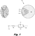
- Fig. 1 is a diagram of a neural lead (102) that has been implanted in proximity to target biological tissue (115).
- the neural lead (102) may be any of a number of different leads, including a cochlear lead, a brain stimulation lead, an optical prosthesis, a spinal cord stimulator, a muscle stimulator, a sensor, or other type of neural lead.
- the neural lead (102) includes an electrode (100) with an exposed surface (101) that makes electrical contact with the surrounding biological tissue.
- the electrode (100) is electrically connected to a signal wire (110) and supported by an implant body (105). Ideally, electrical signals pass down the signal wire (110) to the electrode (100) and from the electrode (100) to the target biological tissue (115).
- the electrode (100) is illustrated as being separated from the target biological tissue (115).
- the electrode (100) may be separated from the target auditory nerve endings by the cochlear fluid and a wall of a cochlear duct.
- the principles described below apply to electrodes that are in direct contact with the target tissue as well as configurations that have intervening fluids and/or tissue between the electrode and target tissue.
- a simplified electrical schematic of the interface between the electrode (100) and the target biological tissue (115) is shown below the cross sectional diagram.
- a first black circle on the right represents the electrode (100) and a second black circle on the left represents the target biological tissue (115).
- a first resistor R1 and a capacitor C1 represent the impedance at the surface of the electrode (100).
- the first resistance R1 and capacitance C1 can be dependent on a number of factors, including the exposed geometric surface area (GSA), the roughness of the electrode and the material that makes up the surface of electrode. For example, increasing the geometric size and/or active surface area of the electrode will increase its exposed surface area and its lower impedance.
- the electrical resistance of the biological environment between the electrode (100) and the target biological tissue (115) is shown by a second resistance R2.
- the second resistance R2 can be dependent on a number of factors including the concentrations of ions and proteins in fluids, the type of intervening tissues, and the distance between the electrode and the target tissue.
- the surface topology of the electrode can have significant effects on the performance of the system. For example, a rough electrode surface may have a greater active surface area in contact with biological tissues/fluids. This reduces the overall impedance at the electrode/tissue interface (R1 is significantly reduced while C1 is somewhat increased).
- electrode surfaces with very high aspect ratios may be prone to surface erosion. For example, peaks of the electrode surface may convey higher electrical currents to the surrounding tissues. These higher electrical currents may cause the peaks to dissolve into the biological tissue. This erosion can be undesirable for a number of reasons, including changes in the electrical characteristics of the electrode and contamination of the biological tissue.
- the surface topology may also influence the biological response of the body to the implant.
- the initial response to the surgical implantation of the electrode is nonspecific adsorption of the proteins to the surface of the implant.
- impedance of the interface increases, with a corresponding increase in power consumption of the implanted device.
- the surface topology, including the pore size, structure spacing/height, and morphology of the electrode surface can influence adhesion of fibroblasts and other connective tissue to the electrode surface.
- the surface topology of the electrode surface can be designed to reduce fibrous tissue formation and reduce surface impedance over the lifetime of the electrode.
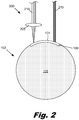
- Fig. 2 shows a cross sectional view of an implantable neural lead (102) that includes a body (105) and an electrode (100) with an exposed surface (101).
- the exposed surface (101) is in electrical contact with the surrounding biological tissues.
- the exposed surface (101) can be modified through application of laser energy.
- a focusing laser system (200) uses a lens (205) or other technique to focus the laser beam (210) onto the exposed surface (101) of the electrode (100).
- This technique may have a number of advantages, including a small spot/feature size and precise location.
- the exposed surface typically needs to be located at the focal point of the laser system, complex fixturing of both the laser and the electrode may be required.
- the use of a focusing laser system for modification of curved electrode surfaces can be even more challenging because the relative position and angle between the laser system and the electrode needs to be changed as the laser is scanned over the surface.
- Excimer lasers are a form of ultraviolet laser that uses noble gasses, including noble gas halides.
- the ultraviolet light from an excimer laser can add enough energy to disrupt the molecular bonds of a surface. This ablates the surface in a tightly controlled manner with almost no heating or change in the remainder of the material.
- the excimer laser can be used to produce localized melting rather than ablation.
- An excimer laser (215) does not typically have tight focusing requirements and can be effectively used at a range of distances to modify an electrode surface (101).
- An excimer laser (215) may be used to modify an electrode surface (101) that has topography variations on the range of 10 to 100 microns.
- a curved electrode surface (101) may have a center portion that is 50 microns higher than the edges of the electrode (100).
- the excimer laser (215) may be rastered across this surface without significant concern about the variation in height. If variations in the electrode surface (101) are greater than the tolerance of the excimer laser system, only coarse adjustments are necessary to bring it back into the acceptable range.
- Fig. 3 is a graph showing illustrative characteristics of an excimer laser (215, Fig. 2 ).
- the horizontal axis shows the duration of individual laser pulses in nanoseconds, with shorter pulses on the left and longer pulses on the right.
- the vertical axis shows intensity, in megawatts per centimeter square, with lower intensities on the bottom of the graph and higher intensities at the top of the graph.
- a third axis labeled ⁇ Tp is at an angle to the vertical axis and shows the surface temperatures generated for a given pulse length and intensity. The temperatures are given in degrees Celsius.
- a number of boxes have been drawn to show the various effects on surfaces the excimer laser is applied to.
- a shaded box labeled “Cleaning” is between 100 and 1,000 degrees Celsius with pulse durations of approximately one to hundreds of nanoseconds and intensities between approximately one and ten megawatts per centimeter square.
- a shaded box labeled “Melting” is between 1,000 and 10,000 degrees Celsius with pulse durations of approximately one nanosecond to hundreds of nanoseconds and intensities between approximately 1 and 100 megawatts per centimeter square.
- the portion labeled “Ablation” shows regions where the intensity and pulse durations produce localized temperatures exceeding 10,000 degrees.
- Fig. 4 shows one example of an illustrative method (400) for surface modification using an excimer laser (215).
- the lead (420) includes a recessed electrode (425) surrounded by an insulating body (430).
- the electrode (425) may be formed from platinum and joined to a silicone body (430).
- the electrode (425) may be placed in a mold and silicone may be injected around the electrode (425) and any wires or traces that are connected to the electrode (425).
- a layer of silicone (435) or other insulating material may be intentionally or unintentionally formed over the electrode (425).
- An excimer laser (215) may be used to remove all or a portion of the overlying silicone layer (435) (block 405).
- Flash Unintentional deposition of silicone over the electrode surface is called "flash.” Flash may be present in various thicknesses over electrode surfaces that were not completely seated against the mold. The parameters of the excimer laser system may be set to ablate the silicone flash with minimal disruption to the electrode surface itself.
- the conductive electrode surface may be intentionally covered with a thicker layer of silicone and an excimer laser (215) may be used to remove all or a portion of the silicone overlying the electrode surface.
- the removal of the overlying silicone layer (435) may result in particulates or other contaminants (440) being deposited on the electrode surface.
- the electrode surface (445) is cleaned to remove any contaminants from the previous operation (block 410).
- the electrode surface (445) may be cleaned using mechanical, chemical, or laser techniques.
- the lead (420) may be placed in an ultrasonic bath with a specific solution and temperature for a predetermined period of time.
- the electrode surface (445) may be cleaned through the application of additional laser energy.
- the electrode surface (445) may be mechanically cleaned.
- the electrode surface (445) is then modified to produce the desired surface texture (445') (block 415).
- an excimer laser (215) is used to ablate or melt the surface (445) of the electrode (425).
- Ablation of the electrode surface (445) is used to roughen the surfaces by producing high aspect ratio features. Appropriate selection of laser pulse length, laser intensity, and location of the laser on the electrode surface can produce the desired surface roughness.
- the high aspect ratio features may cover all or only a portion of the exposed surface.
- Fig. 5 shows one example where an additional electroplated coating is added to the electrode surface and then subsequently modified through application of laser energy.
- the electrode surface was electroplated using techniques that specifically increase the surface roughness.
- the electroplating material (500) may be the same or different than the underlying electrode material. The electroplating may be performed before the electrodes are encapsulated or after the electrode surface has been cleaned.
- the modified surface (505) has larger surface features and smoother profiles than the original electroplated material (500). This reduces the tendency of the peaks to dissolve.
- features with specific sizes and morphology can be formed. The sizes of the surface features can be selected to reduce adhesion of fibrous material to the electrode surface. As discussed above, adhesion of fibrous material to the electrode surface can increase the system impedance.
- the modification of the electrode surface using an excimer laser may be a two-step process.
- the excimer laser may be rastered over the electrode surface using high energy ablative settings to produce a high aspect ratio surface roughness.
- the high aspect surface roughness may cover all or only a portion of the exposed surface.
- the excimer laser may then be rastered over the electrode surface using lower energy settings to melt/consolidate peaks on the surface. This may create a porous structure.
- the melted/consolidated areas may cover all or only a portion of the high aspect ratio surface roughness.
- Fig. 6 shows an illustration of an electrode surface that has been selectively modified using an excimer laser.
- the excimer laser has been used to consolidate a high aspect ratio surface (600) to produce alternating stripes of high aspect ratio surface and laser consolidated surface (605).
- This change in surface roughness may serve a variety of purposes, including decreasing dissolution of electrode material and decreasing fibrous adhesion to the electrode surface.
- adding discontinuities in the electrode surface roughness may further reduce the impedance of the electrode. For example, the current density over the surface of the electrode increases at edges or other discontinuities. For a fixed electrode conductive area, an increase in the length of the edges or other discontinuities over the electrode surface can decrease impedance.
- an additional impedance reducing coating may be formed over the electrode surface.
- Figs. 7A, 7B, and 8 show various examples where an impedance reducing coating has been formed over the electrode surface.
- the impedance reducing coating may include platinum black, platinum gray, platinum/iridium alloys, dealloyed surfaces, conductive nanostructures or other materials.
- conductive polymers such as poly(3,4-ethylenedioxythiophene (PEDOT) could be used in an impedance reducing coating.
- PEDOT poly(3,4-ethylenedioxythiophene
- the impedance reducing coatings may be applied in a number of ways, including electrochemical deposition, electrostatic deposition, printing, manual application, or other technique.
- electrochemical deposition electrochemical deposition
- electrostatic deposition printing
- manual application or other technique.
- an ink containing platinum, iridium, or other conductive nanostructures may be printed onto the electrode surfaces using ink jet techniques.
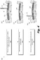
- Fig. 7A shows an impedance reducing coating (700) disposed over the electrode (705).
- Fig. 7B shows the same impedance reducing coating (700) and electrode (705) with selected portions that have been modified using an excimer laser.
- the laser modified portions (710) have melted and combined the impedance reducing coating (700) and the underlying electrode material.
- the laser modified portions (710) may or may not cover the entire surface of the electrode (705).
- the impedance reducing coating (700) is more securely attached to the underlying electrode (705).
- the laser modified portions (710) may increase the surface area of the electrode (705) and decrease adhesion of fibrous tissue to the electrode surface.
- the impedance reducing coating (700) may be applied after the application of the laser energy.
- Fig. 8 shows one example of an electrode (800) with an excimer laser modified surface (805) and an impedance reducing overcoat (810).
- the impedance reducing coating (810) is formed on this excimer laser modified surface (805), the coating (810) can extend into these features to mechanically lock the coating (810) in place.
- the laser modification of the surface can be applied to the electrode surface itself or to a surface that is deposited over the electrode.
- the surface modification increases the electrochemical surface area of an electrode.
- the overcoat may have a charge transfer capability that is greater than that of the electrode surface.
- Surface modification of the electrode may also help impedance reducing coatings to more securely attach to the electrode.
- the modified surface may have feature sizes and distribution that inhibit adhesion and growth of biological tissues on the surface.
- the power consumption of the device can be significantly reduced.
- Lower power consumption and longer battery life will provide possibility for new system architectures such as fully implantable cochlear systems.
Landscapes
- Engineering & Computer Science (AREA)
- Health & Medical Sciences (AREA)
- Physics & Mathematics (AREA)
- Optics & Photonics (AREA)
- Mechanical Engineering (AREA)
- Plasma & Fusion (AREA)
- Life Sciences & Earth Sciences (AREA)
- General Health & Medical Sciences (AREA)
- Public Health (AREA)
- Biomedical Technology (AREA)
- Animal Behavior & Ethology (AREA)
- Veterinary Medicine (AREA)
- Neurology (AREA)
- Neurosurgery (AREA)
- Heart & Thoracic Surgery (AREA)
- Nuclear Medicine, Radiotherapy & Molecular Imaging (AREA)
- Radiology & Medical Imaging (AREA)
- Orthopedic Medicine & Surgery (AREA)
- Cardiology (AREA)
- Surgery (AREA)
- Medical Informatics (AREA)
- Molecular Biology (AREA)
- Pathology (AREA)
- Biophysics (AREA)
- Electrotherapy Devices (AREA)
Claims (15)
- Verfahren zum Bilden einer implantierbaren Elektrode (100, 425, 705, 800), wobei:eine leitende Oberfläche (101, 445) der implantierbaren Elektrode mit einer ersten Anwendung eines Excimer-Lasers (215) freigelegt wird;eine erste Oberflächentextur auf einer leitenden Oberfläche erzeugt wird, indem die Oberflächenrauhigkeit mittels einer Oberflächenablationsanwendung des Excimer-Lasers oder mittels Ausbilden einer galvanisch hergestellten Oberfläche (500) über der leitenden Oberfläche erhöht wird; unddie erste Oberflächentextur mittels Schmelzen und Konsolidieren von Spitzen der ersten Oberflächentextur mittels nachfolgender Anwendung des Excimer-Lasers modifiziert wird, um eine zweite Oberflächentextur herzustellen.
- Verfahren gemäß Anspruch 1, wobei beim Erzeugen der ersten Oberflächentextur ein Excimer-Laserstrahl (215) über einen galvanisch hergestellten Überzug (500) auf der leitenden Oberfläche (101, 445) gerastert wird.
- Verfahren gemäß Anspruch 1, wobei die erste Oberflächentextur weniger als die Gesamtheit einer freigelegten Oberfläche der leitenden Oberfläche (101, 445) bedeckt.
- Verfahren gemäß Anspruch 1, wobei das Modifizieren der ersten Oberflächentextur zwecks Erzeugen einer zweiten Oberflächentextur scharfe Spitzen reduziert, um eine zweite Oberflächentextur mit verringerter Spitzenauflösung zu erzeugen.
- Verfahren gemäß Anspruch 4, wobei beim Modifizieren der ersten Oberflächentextur zwecks Erzeugen der zweiten Oberflächentextur der Excimer-Laser (215) über die erste Oberflächentextur gerastert wird, um Spitzen der ersten Oberflächentextur zu restrukturieren.
- Verfahren gemäß Anspruch 1, wobei die zweite Oberflächentextur weniger als die Gesamtheit der ersten Oberflächentextur bedeckt.
- Verfahren gemäß Anspruch 1, wobei ferner ein Impedanz verringernder Überzug (700, 810) über der leitenden Oberfläche angeordnet wird.
- Verfahren gemäß Anspruch 7, wobei der Impedanz verringernde Überzug (700, 810) Platinschwarz, Platingrau, eine Platin-Iridium-Legierung, aktiviertes Iridiumoxid, leitende Nanostrukturen und/oder leitende Polymere aufweist.
- Verfahren gemäß Anspruch 7, wobei beim Aufbringen des Impedanz reduzierenden Überzugs (700, 810) über der leitenden Oberfläche Platintinte über die leitende Oberfläche gedruckt wird.
- Verfahren gemäß Anspruch 7, wobei die zweite Oberflächentextur überhängende Oberflächenmerkmale aufweist und wobei der Impedanz reduzierende Überzug (700, 810) die überhängenden Oberflächenstrukturen überdeckt.
- Verfahren gemäß Anspruch 1, wobei die leitende Oberfläche (101, 445) ein erstes Edelmetall und die galvanisch hergestellte Oberfläche (500) ein zweites Edelmetall aufweist.
- Verfahren gemäß Anspruch 1, wobei das erste Edelmetall Platin aufweist und das zweite Edelmetall Platin aufweist.
- Verfahren gemäß Anspruch 11, wobei das Erzeugen der zweiten Oberflächenstruktur auf der leitenden Oberfläche mit dem Excimer-Laser (215) eine Legierung zwischen der mittels Galvanisieren hergestellten Oberfläche (500) und der leitenden Oberfläche (101, 445) bildet.
- Verfahren gemäß Anspruch 1, wobei ferner ein Platinblech gefaltet wird, um die leitende Oberfläche (101, 445) zu bilden, und wobei Silikon (435) um die leitende Oberfläche herum mittels Flüssigspritzguss eingebracht wird.
- Verfahren gemäß Anspruch 14, wobei ferner mittels eines Laserablationsverfahrens Silikongrate (435) von der leitenden Oberfläche (445) entfernt werden.
Applications Claiming Priority (1)
| Application Number | Priority Date | Filing Date | Title |
|---|---|---|---|
| PCT/US2013/055102 WO2015023280A1 (en) | 2013-08-15 | 2013-08-15 | Surface modified electrodes |
Publications (2)
| Publication Number | Publication Date |
|---|---|
| EP3033197A1 EP3033197A1 (de) | 2016-06-22 |
| EP3033197B1 true EP3033197B1 (de) | 2020-04-22 |
Family
ID=49004091
Family Applications (1)
| Application Number | Title | Priority Date | Filing Date |
|---|---|---|---|
| EP13751085.5A Active EP3033197B1 (de) | 2013-08-15 | 2013-08-15 | Verfahren zur bildung einer implantierbaren elektrode |
Country Status (3)
| Country | Link |
|---|---|
| US (1) | US10827936B2 (de) |
| EP (1) | EP3033197B1 (de) |
| WO (1) | WO2015023280A1 (de) |
Cited By (1)
| Publication number | Priority date | Publication date | Assignee | Title |
|---|---|---|---|---|
| DE102022202437A1 (de) | 2021-03-12 | 2022-09-15 | Heraeus Deutschland GmbH & Co. KG | Verfahren zum Herstellen eines ablatierten Leiters |
Families Citing this family (11)
| Publication number | Priority date | Publication date | Assignee | Title |
|---|---|---|---|---|
| US10058697B2 (en) | 2013-08-27 | 2018-08-28 | Advanced Bionics Ag | Thermoformed electrode arrays |
| US10058699B2 (en) | 2013-08-27 | 2018-08-28 | Advanced Bionics Ag | Implantable leads with flag extensions |
| US10058698B2 (en) | 2013-08-27 | 2018-08-28 | Advanced Bionics Ag | Asymmetric cochlear implant electrodes and method |
| US10328268B2 (en) | 2014-09-04 | 2019-06-25 | AtaCor Medical, Inc. | Cardiac pacing |
| US11097109B2 (en) | 2014-11-24 | 2021-08-24 | AtaCor Medical, Inc. | Cardiac pacing sensing and control |
| US20200194771A1 (en) * | 2018-12-12 | 2020-06-18 | NeuroTronik IP Holding (Jersey) Limited | Medical electrodes having enhanced charge capacities, and methods of manufacturing |
| US12208260B2 (en) | 2019-05-29 | 2025-01-28 | Kurin, Inc. | Implantable electrical leads and electrodes |
| US11666771B2 (en) | 2020-05-29 | 2023-06-06 | AtaCor Medical, Inc. | Implantable electrical leads and associated delivery systems |
| WO2023095036A1 (en) | 2021-11-24 | 2023-06-01 | AtaCor Medical, Inc. | Implantable electrical leads and associated delivery and control systems |
| CN116077829B (zh) * | 2023-01-18 | 2023-12-15 | 微智医疗器械有限公司 | 植入装置和电刺激器以及电极电镀方法 |
| WO2025019865A2 (en) * | 2023-07-20 | 2025-01-23 | Technimark Llc | Apparatus and method for laser retexturing |
Family Cites Families (16)
| Publication number | Priority date | Publication date | Assignee | Title |
|---|---|---|---|---|
| US5473138A (en) * | 1993-07-13 | 1995-12-05 | Singh; Rajiv K. | Method for increasing the surface area of ceramics, metals and composites |
| US5683443A (en) * | 1995-02-07 | 1997-11-04 | Intermedics, Inc. | Implantable stimulation electrodes with non-native metal oxide coating mixtures |
| US5800500A (en) | 1995-08-18 | 1998-09-01 | Pi Medical Corporation | Cochlear implant with shape memory material and method for implanting the same |
| AU8681098A (en) * | 1997-08-01 | 1999-03-08 | Massachusetts Institute Of Technology | Three-dimensional polymer matrices |
| JP2001158813A (ja) | 1999-10-27 | 2001-06-12 | Novartis Ag | 材料表面を被覆する方法 |
| US6869712B2 (en) * | 2002-03-07 | 2005-03-22 | Hewlett-Packard Development Company, L.P. | Ion exchange system structure with a microtextured surface, method of manufacture, and method of use thereof |
| US6974533B2 (en) * | 2002-04-11 | 2005-12-13 | Second Sight Medical Products, Inc. | Platinum electrode and method for manufacturing the same |
| US20050211680A1 (en) * | 2003-05-23 | 2005-09-29 | Mingwei Li | Systems and methods for laser texturing of surfaces of a substrate |
| US8099172B2 (en) * | 2006-04-28 | 2012-01-17 | Advanced Neuromodulation Systems, Inc. | Spinal cord stimulation paddle lead and method of making the same |
| US20110130815A1 (en) * | 2009-12-01 | 2011-06-02 | Peter Gibson | Contoured electrode contact surfaces |
| US8461042B2 (en) | 2009-12-01 | 2013-06-11 | Cochlear Limited | Electrode contact contaminate removal |
| US8782884B2 (en) | 2009-12-01 | 2014-07-22 | Cochlear Limited | Manufacturing an electrode assembly having contoured electrode contact surfaces |
| EP2563464B1 (de) * | 2010-04-30 | 2018-06-06 | Second Sight Medical Products, Inc. | Verbessertes biokompatibles bindungsverfahren |
| WO2013036988A1 (en) | 2011-09-13 | 2013-03-21 | Hear Ip Pty Ltd | Biocompatible electrode component and method for fabrication thereof |
| JP2013074956A (ja) | 2011-09-30 | 2013-04-25 | Nidek Co Ltd | 生体組織用刺激電極及び該刺激電極の加工方法 |
| US10791945B2 (en) * | 2013-05-30 | 2020-10-06 | Pulse Ip, Llc | Biocompatible implantable electrode |
-
2013
- 2013-08-15 EP EP13751085.5A patent/EP3033197B1/de active Active
- 2013-08-15 WO PCT/US2013/055102 patent/WO2015023280A1/en not_active Ceased
- 2013-08-15 US US14/907,409 patent/US10827936B2/en active Active
Non-Patent Citations (1)
| Title |
|---|
| None * |
Cited By (1)
| Publication number | Priority date | Publication date | Assignee | Title |
|---|---|---|---|---|
| DE102022202437A1 (de) | 2021-03-12 | 2022-09-15 | Heraeus Deutschland GmbH & Co. KG | Verfahren zum Herstellen eines ablatierten Leiters |
Also Published As
| Publication number | Publication date |
|---|---|
| US20160174860A1 (en) | 2016-06-23 |
| US10827936B2 (en) | 2020-11-10 |
| WO2015023280A1 (en) | 2015-02-19 |
| EP3033197A1 (de) | 2016-06-22 |
Similar Documents
| Publication | Publication Date | Title |
|---|---|---|
| EP3033197B1 (de) | Verfahren zur bildung einer implantierbaren elektrode | |
| US5630839A (en) | Multi-electrode cochlear implant and method of manufacturing the same | |
| Schuettler et al. | Fabrication of implantable microelectrode arrays by laser cutting of silicone rubber and platinum foil | |
| US5800500A (en) | Cochlear implant with shape memory material and method for implanting the same | |
| AU2020202344B2 (en) | Biomedical electrode | |
| US20100036470A1 (en) | Laser-Based Fabrication of Implantable Stimulation Electrodes | |
| US20100305673A1 (en) | Ink Jet Printing of Implantable Electrodes | |
| US8782884B2 (en) | Manufacturing an electrode assembly having contoured electrode contact surfaces | |
| WO2009050168A1 (en) | Drug-eluting nanowire array | |
| US20110130815A1 (en) | Contoured electrode contact surfaces | |
| JP2013074956A (ja) | 生体組織用刺激電極及び該刺激電極の加工方法 | |
| AU2014202893B2 (en) | Biocompatible implantable electrode | |
| JP5313255B2 (ja) | 最適表面組織形状 | |
| CN104394926A (zh) | 用于制造电极结构的方法 | |
| US20220361323A1 (en) | Methods and systems for fabricating 3d multielectrode arrays with 3d printed electrodes | |
| Li et al. | Hierarchical platinum–iridium neural electrodes structured by femtosecond laser for superwicking interface and superior charge storage capacity | |
| CN101504885B (zh) | 电容器元件的制造方法 | |
| EP2800589A1 (de) | Poröse entlegierte elektroden | |
| US20110127243A1 (en) | Electrode contact contaminate removal | |
| Butt et al. | Three-dimensional electro-neural interfaces electroplated on subretinal prostheses | |
| EP2991798A1 (de) | Oberflächenstrukturierung von metallen | |
| WO1996022864A1 (en) | Laser-machineable articles | |
| CN114602059B (zh) | 电极触点的加工方法及植入式电极 | |
| WO2026003268A2 (en) | Methods of manufacturing and devices | |
| CA2108495A1 (en) | Implantable microelectrode |
Legal Events
| Date | Code | Title | Description |
|---|---|---|---|
| PUAI | Public reference made under article 153(3) epc to a published international application that has entered the european phase |
Free format text: ORIGINAL CODE: 0009012 |
|
| 17P | Request for examination filed |
Effective date: 20160218 |
|
| AK | Designated contracting states |
Kind code of ref document: A1 Designated state(s): AL AT BE BG CH CY CZ DE DK EE ES FI FR GB GR HR HU IE IS IT LI LT LU LV MC MK MT NL NO PL PT RO RS SE SI SK SM TR |
|
| AX | Request for extension of the european patent |
Extension state: BA ME |
|
| DAX | Request for extension of the european patent (deleted) | ||
| GRAP | Despatch of communication of intention to grant a patent |
Free format text: ORIGINAL CODE: EPIDOSNIGR1 |
|
| STAA | Information on the status of an ep patent application or granted ep patent |
Free format text: STATUS: GRANT OF PATENT IS INTENDED |
|
| INTG | Intention to grant announced |
Effective date: 20191121 |
|
| GRAS | Grant fee paid |
Free format text: ORIGINAL CODE: EPIDOSNIGR3 |
|
| GRAA | (expected) grant |
Free format text: ORIGINAL CODE: 0009210 |
|
| STAA | Information on the status of an ep patent application or granted ep patent |
Free format text: STATUS: THE PATENT HAS BEEN GRANTED |
|
| AK | Designated contracting states |
Kind code of ref document: B1 Designated state(s): AL AT BE BG CH CY CZ DE DK EE ES FI FR GB GR HR HU IE IS IT LI LT LU LV MC MK MT NL NO PL PT RO RS SE SI SK SM TR |
|
| REG | Reference to a national code |
Ref country code: GB Ref legal event code: FG4D |
|
| REG | Reference to a national code |
Ref country code: CH Ref legal event code: EP |
|
| REG | Reference to a national code |
Ref country code: IE Ref legal event code: FG4D |
|
| REG | Reference to a national code |
Ref country code: DE Ref legal event code: R096 Ref document number: 602013068165 Country of ref document: DE |
|
| REG | Reference to a national code |
Ref country code: AT Ref legal event code: REF Ref document number: 1259435 Country of ref document: AT Kind code of ref document: T Effective date: 20200515 |
|
| REG | Reference to a national code |
Ref country code: LT Ref legal event code: MG4D |
|
| REG | Reference to a national code |
Ref country code: NL Ref legal event code: MP Effective date: 20200422 |
|
| PG25 | Lapsed in a contracting state [announced via postgrant information from national office to epo] |
Ref country code: NL Free format text: LAPSE BECAUSE OF FAILURE TO SUBMIT A TRANSLATION OF THE DESCRIPTION OR TO PAY THE FEE WITHIN THE PRESCRIBED TIME-LIMIT Effective date: 20200422 Ref country code: SE Free format text: LAPSE BECAUSE OF FAILURE TO SUBMIT A TRANSLATION OF THE DESCRIPTION OR TO PAY THE FEE WITHIN THE PRESCRIBED TIME-LIMIT Effective date: 20200422 Ref country code: LT Free format text: LAPSE BECAUSE OF FAILURE TO SUBMIT A TRANSLATION OF THE DESCRIPTION OR TO PAY THE FEE WITHIN THE PRESCRIBED TIME-LIMIT Effective date: 20200422 Ref country code: PT Free format text: LAPSE BECAUSE OF FAILURE TO SUBMIT A TRANSLATION OF THE DESCRIPTION OR TO PAY THE FEE WITHIN THE PRESCRIBED TIME-LIMIT Effective date: 20200824 Ref country code: IS Free format text: LAPSE BECAUSE OF FAILURE TO SUBMIT A TRANSLATION OF THE DESCRIPTION OR TO PAY THE FEE WITHIN THE PRESCRIBED TIME-LIMIT Effective date: 20200822 Ref country code: GR Free format text: LAPSE BECAUSE OF FAILURE TO SUBMIT A TRANSLATION OF THE DESCRIPTION OR TO PAY THE FEE WITHIN THE PRESCRIBED TIME-LIMIT Effective date: 20200723 Ref country code: NO Free format text: LAPSE BECAUSE OF FAILURE TO SUBMIT A TRANSLATION OF THE DESCRIPTION OR TO PAY THE FEE WITHIN THE PRESCRIBED TIME-LIMIT Effective date: 20200722 Ref country code: FI Free format text: LAPSE BECAUSE OF FAILURE TO SUBMIT A TRANSLATION OF THE DESCRIPTION OR TO PAY THE FEE WITHIN THE PRESCRIBED TIME-LIMIT Effective date: 20200422 |
|
| REG | Reference to a national code |
Ref country code: AT Ref legal event code: MK05 Ref document number: 1259435 Country of ref document: AT Kind code of ref document: T Effective date: 20200422 |
|
| PG25 | Lapsed in a contracting state [announced via postgrant information from national office to epo] |
Ref country code: BG Free format text: LAPSE BECAUSE OF FAILURE TO SUBMIT A TRANSLATION OF THE DESCRIPTION OR TO PAY THE FEE WITHIN THE PRESCRIBED TIME-LIMIT Effective date: 20200722 Ref country code: RS Free format text: LAPSE BECAUSE OF FAILURE TO SUBMIT A TRANSLATION OF THE DESCRIPTION OR TO PAY THE FEE WITHIN THE PRESCRIBED TIME-LIMIT Effective date: 20200422 Ref country code: HR Free format text: LAPSE BECAUSE OF FAILURE TO SUBMIT A TRANSLATION OF THE DESCRIPTION OR TO PAY THE FEE WITHIN THE PRESCRIBED TIME-LIMIT Effective date: 20200422 Ref country code: LV Free format text: LAPSE BECAUSE OF FAILURE TO SUBMIT A TRANSLATION OF THE DESCRIPTION OR TO PAY THE FEE WITHIN THE PRESCRIBED TIME-LIMIT Effective date: 20200422 |
|
| PG25 | Lapsed in a contracting state [announced via postgrant information from national office to epo] |
Ref country code: AL Free format text: LAPSE BECAUSE OF FAILURE TO SUBMIT A TRANSLATION OF THE DESCRIPTION OR TO PAY THE FEE WITHIN THE PRESCRIBED TIME-LIMIT Effective date: 20200422 |
|
| REG | Reference to a national code |
Ref country code: DE Ref legal event code: R097 Ref document number: 602013068165 Country of ref document: DE |
|
| PG25 | Lapsed in a contracting state [announced via postgrant information from national office to epo] |
Ref country code: EE Free format text: LAPSE BECAUSE OF FAILURE TO SUBMIT A TRANSLATION OF THE DESCRIPTION OR TO PAY THE FEE WITHIN THE PRESCRIBED TIME-LIMIT Effective date: 20200422 Ref country code: SM Free format text: LAPSE BECAUSE OF FAILURE TO SUBMIT A TRANSLATION OF THE DESCRIPTION OR TO PAY THE FEE WITHIN THE PRESCRIBED TIME-LIMIT Effective date: 20200422 Ref country code: IT Free format text: LAPSE BECAUSE OF FAILURE TO SUBMIT A TRANSLATION OF THE DESCRIPTION OR TO PAY THE FEE WITHIN THE PRESCRIBED TIME-LIMIT Effective date: 20200422 Ref country code: AT Free format text: LAPSE BECAUSE OF FAILURE TO SUBMIT A TRANSLATION OF THE DESCRIPTION OR TO PAY THE FEE WITHIN THE PRESCRIBED TIME-LIMIT Effective date: 20200422 Ref country code: DK Free format text: LAPSE BECAUSE OF FAILURE TO SUBMIT A TRANSLATION OF THE DESCRIPTION OR TO PAY THE FEE WITHIN THE PRESCRIBED TIME-LIMIT Effective date: 20200422 Ref country code: CZ Free format text: LAPSE BECAUSE OF FAILURE TO SUBMIT A TRANSLATION OF THE DESCRIPTION OR TO PAY THE FEE WITHIN THE PRESCRIBED TIME-LIMIT Effective date: 20200422 Ref country code: RO Free format text: LAPSE BECAUSE OF FAILURE TO SUBMIT A TRANSLATION OF THE DESCRIPTION OR TO PAY THE FEE WITHIN THE PRESCRIBED TIME-LIMIT Effective date: 20200422 Ref country code: ES Free format text: LAPSE BECAUSE OF FAILURE TO SUBMIT A TRANSLATION OF THE DESCRIPTION OR TO PAY THE FEE WITHIN THE PRESCRIBED TIME-LIMIT Effective date: 20200422 |
|
| PG25 | Lapsed in a contracting state [announced via postgrant information from national office to epo] |
Ref country code: SK Free format text: LAPSE BECAUSE OF FAILURE TO SUBMIT A TRANSLATION OF THE DESCRIPTION OR TO PAY THE FEE WITHIN THE PRESCRIBED TIME-LIMIT Effective date: 20200422 Ref country code: PL Free format text: LAPSE BECAUSE OF FAILURE TO SUBMIT A TRANSLATION OF THE DESCRIPTION OR TO PAY THE FEE WITHIN THE PRESCRIBED TIME-LIMIT Effective date: 20200422 |
|
| PLBE | No opposition filed within time limit |
Free format text: ORIGINAL CODE: 0009261 |
|
| STAA | Information on the status of an ep patent application or granted ep patent |
Free format text: STATUS: NO OPPOSITION FILED WITHIN TIME LIMIT |
|
| 26N | No opposition filed |
Effective date: 20210125 |
|
| PG25 | Lapsed in a contracting state [announced via postgrant information from national office to epo] |
Ref country code: MC Free format text: LAPSE BECAUSE OF FAILURE TO SUBMIT A TRANSLATION OF THE DESCRIPTION OR TO PAY THE FEE WITHIN THE PRESCRIBED TIME-LIMIT Effective date: 20200422 |
|
| REG | Reference to a national code |
Ref country code: CH Ref legal event code: PL |
|
| PG25 | Lapsed in a contracting state [announced via postgrant information from national office to epo] |
Ref country code: LU Free format text: LAPSE BECAUSE OF NON-PAYMENT OF DUE FEES Effective date: 20200815 Ref country code: CH Free format text: LAPSE BECAUSE OF NON-PAYMENT OF DUE FEES Effective date: 20200831 Ref country code: LI Free format text: LAPSE BECAUSE OF NON-PAYMENT OF DUE FEES Effective date: 20200831 |
|
| REG | Reference to a national code |
Ref country code: BE Ref legal event code: MM Effective date: 20200831 |
|
| PG25 | Lapsed in a contracting state [announced via postgrant information from national office to epo] |
Ref country code: SI Free format text: LAPSE BECAUSE OF FAILURE TO SUBMIT A TRANSLATION OF THE DESCRIPTION OR TO PAY THE FEE WITHIN THE PRESCRIBED TIME-LIMIT Effective date: 20200422 |
|
| PG25 | Lapsed in a contracting state [announced via postgrant information from national office to epo] |
Ref country code: FR Free format text: LAPSE BECAUSE OF NON-PAYMENT OF DUE FEES Effective date: 20200831 |
|
| PG25 | Lapsed in a contracting state [announced via postgrant information from national office to epo] |
Ref country code: IE Free format text: LAPSE BECAUSE OF NON-PAYMENT OF DUE FEES Effective date: 20200815 Ref country code: BE Free format text: LAPSE BECAUSE OF NON-PAYMENT OF DUE FEES Effective date: 20200831 |
|
| PG25 | Lapsed in a contracting state [announced via postgrant information from national office to epo] |
Ref country code: TR Free format text: LAPSE BECAUSE OF FAILURE TO SUBMIT A TRANSLATION OF THE DESCRIPTION OR TO PAY THE FEE WITHIN THE PRESCRIBED TIME-LIMIT Effective date: 20200422 Ref country code: MT Free format text: LAPSE BECAUSE OF FAILURE TO SUBMIT A TRANSLATION OF THE DESCRIPTION OR TO PAY THE FEE WITHIN THE PRESCRIBED TIME-LIMIT Effective date: 20200422 Ref country code: CY Free format text: LAPSE BECAUSE OF FAILURE TO SUBMIT A TRANSLATION OF THE DESCRIPTION OR TO PAY THE FEE WITHIN THE PRESCRIBED TIME-LIMIT Effective date: 20200422 |
|
| PG25 | Lapsed in a contracting state [announced via postgrant information from national office to epo] |
Ref country code: MK Free format text: LAPSE BECAUSE OF FAILURE TO SUBMIT A TRANSLATION OF THE DESCRIPTION OR TO PAY THE FEE WITHIN THE PRESCRIBED TIME-LIMIT Effective date: 20200422 |
|
| PGFP | Annual fee paid to national office [announced via postgrant information from national office to epo] |
Ref country code: DE Payment date: 20250827 Year of fee payment: 13 |
|
| PGFP | Annual fee paid to national office [announced via postgrant information from national office to epo] |
Ref country code: GB Payment date: 20250827 Year of fee payment: 13 |