EP3032890A1 - Benutzerendgerät, basisstation und drahtloskommunikationsverfahren - Google Patents
Benutzerendgerät, basisstation und drahtloskommunikationsverfahren Download PDFInfo
- Publication number
- EP3032890A1 EP3032890A1 EP14833978.1A EP14833978A EP3032890A1 EP 3032890 A1 EP3032890 A1 EP 3032890A1 EP 14833978 A EP14833978 A EP 14833978A EP 3032890 A1 EP3032890 A1 EP 3032890A1
- Authority
- EP
- European Patent Office
- Prior art keywords
- base station
- received power
- cell
- detection
- small
- Prior art date
- Legal status (The legal status is an assumption and is not a legal conclusion. Google has not performed a legal analysis and makes no representation as to the accuracy of the status listed.)
- Withdrawn
Links
Images


Classifications
-
- H—ELECTRICITY
- H04—ELECTRIC COMMUNICATION TECHNIQUE
- H04W—WIRELESS COMMUNICATION NETWORKS
- H04W48/00—Access restriction; Network selection; Access point selection
- H04W48/16—Discovering, processing access restriction or access information
-
- H—ELECTRICITY
- H04—ELECTRIC COMMUNICATION TECHNIQUE
- H04W—WIRELESS COMMUNICATION NETWORKS
- H04W72/00—Local resource management
- H04W72/20—Control channels or signalling for resource management
- H04W72/23—Control channels or signalling for resource management in the downlink direction of a wireless link, i.e. towards a terminal
-
- H—ELECTRICITY
- H04—ELECTRIC COMMUNICATION TECHNIQUE
- H04B—TRANSMISSION
- H04B17/00—Monitoring; Testing
- H04B17/30—Monitoring; Testing of propagation channels
- H04B17/309—Measuring or estimating channel quality parameters
- H04B17/318—Received signal strength
-
- H—ELECTRICITY
- H04—ELECTRIC COMMUNICATION TECHNIQUE
- H04W—WIRELESS COMMUNICATION NETWORKS
- H04W16/00—Network planning, e.g. coverage or traffic planning tools; Network deployment, e.g. resource partitioning or cells structures
- H04W16/24—Cell structures
- H04W16/32—Hierarchical cell structures
-
- H—ELECTRICITY
- H04—ELECTRIC COMMUNICATION TECHNIQUE
- H04W—WIRELESS COMMUNICATION NETWORKS
- H04W52/00—Power management, e.g. TPC [Transmission Power Control], power saving or power classes
- H04W52/02—Power saving arrangements
- H04W52/0203—Power saving arrangements in the radio access network or backbone network of wireless communication networks
- H04W52/0206—Power saving arrangements in the radio access network or backbone network of wireless communication networks in access points, e.g. base stations
-
- H—ELECTRICITY
- H04—ELECTRIC COMMUNICATION TECHNIQUE
- H04W—WIRELESS COMMUNICATION NETWORKS
- H04W72/00—Local resource management
- H04W72/20—Control channels or signalling for resource management
- H04W72/21—Control channels or signalling for resource management in the uplink direction of a wireless link, i.e. towards the network
-
- H—ELECTRICITY
- H04—ELECTRIC COMMUNICATION TECHNIQUE
- H04W—WIRELESS COMMUNICATION NETWORKS
- H04W84/00—Network topologies
- H04W84/02—Hierarchically pre-organised networks, e.g. paging networks, cellular networks, WLAN [Wireless Local Area Network] or WLL [Wireless Local Loop]
- H04W84/04—Large scale networks; Deep hierarchical networks
- H04W84/042—Public Land Mobile systems, e.g. cellular systems
- H04W84/045—Public Land Mobile systems, e.g. cellular systems using private Base Stations, e.g. femto Base Stations, home Node B
-
- Y—GENERAL TAGGING OF NEW TECHNOLOGICAL DEVELOPMENTS; GENERAL TAGGING OF CROSS-SECTIONAL TECHNOLOGIES SPANNING OVER SEVERAL SECTIONS OF THE IPC; TECHNICAL SUBJECTS COVERED BY FORMER USPC CROSS-REFERENCE ART COLLECTIONS [XRACs] AND DIGESTS
- Y02—TECHNOLOGIES OR APPLICATIONS FOR MITIGATION OR ADAPTATION AGAINST CLIMATE CHANGE
- Y02D—CLIMATE CHANGE MITIGATION TECHNOLOGIES IN INFORMATION AND COMMUNICATION TECHNOLOGIES [ICT], I.E. INFORMATION AND COMMUNICATION TECHNOLOGIES AIMING AT THE REDUCTION OF THEIR OWN ENERGY USE
- Y02D30/00—Reducing energy consumption in communication networks
- Y02D30/70—Reducing energy consumption in communication networks in wireless communication networks
Definitions
- the present invention relates to a base station, a user terminal and a radio communication method in a next-generation mobile communication system.
- LTE Long-term evolution
- OFDMA Orthogonal Frequency Division Multiple Access
- SC-FDMA Single-Carrier Frequency Division Multiple Access
- LTE-advanced LTE-advanced
- LTE enhancement LTE enhancement
- a HetNet Heterogeneous Network
- small cells for example, pico cells, femto cells and so on
- small cells for example, pico cells, femto cells and so on
- a macro cell having a wide coverage area of a radius of approximately several kilometers
- a study is in progress to use carriers of different frequency bands between the macro cell (macro base station) and the small cells (small base stations), in addition to the same frequency band.
- small cells may be placed in the macro cell.
- small cells small base stations
- the transition from the on state to the off state may be decided by monitoring the small cells' traffic from the network side.
- the transition from the off state to the on state needs to be controlled by adequately identifying the traffic that is produced in off-state small cell areas.
- the DL signals reference signals, data signals, etc.
- the present invention has been made in view of the above, and it is therefore an object of the present invention to provide a radio communication method, a user terminal and a base station, whereby, in a structure in which small cells and macro cells are arranged to overlap each other, the small cells (small base stations) can be adequately controlled on/off.
- One aspect of a user terminal provides a user terminal that can communicate with a macro base station that forms a macro cell and a small base station that forms a small cell arranged within the macro cell, and that has a measurement section that measures received power of a detection/measurement signal that is transmitted from the small base station in a predetermined subframe, and total received power of a downlink signal in a subframe in which the detection/measurement signal is not transmitted, a calculation section that calculates received quality by using the received power and the total received power, and a transmission section that transmits information related to the received quality to the macro base station, and, in this user terminal, the calculation section calculates the received quality based on a proportion of the received power and a value given by adding the received power to the total received power.
- FIG. 1 is a conceptual diagram of the HetNet that is assumed in Rel. 12 and later versions.
- a HetNet refers to a radio communication system in which macro cells and small cells are arranged to overlap each other geographically at least in part.
- a HetNet is comprised of a radio base station that forms a macro cell (hereinafter referred to as a "macro base station"), radio base stations that form small cells (hereinafter referred to as "small base stations”), and a user terminal that communicates with the macro base station and the small base stations.
- macro base station radio base station that forms a macro cell
- small base stations radio base stations that form small cells
- a carrier F1 (hereinafter referred to as the "low frequency band carrier") of a relatively low frequency band -- for example, 800 MHz or 2 GHz -- is used.
- a carrier F2 (hereinafter referred to as the "high frequency band carrier”) of a relatively high frequency band -- for example, 3.5 GHz -- is used.
- 800 MHz, 2 GHz and 3.5 GHz are only examples.
- 3.5 GHz may be used for the carrier for the macro cells M, and 800 MHz, 2 GHz, 1.7 GHz and others may be used for the carrier for the small cells S.
- the distribution of users and traffic are not fixed, but change over time or between locations. Consequently, when many small cells are placed in a macro cell, the small cells may be arranged in such a manner that their density and environment vary (sparse and dense) between locations, as shown in above FIG. 1 .
- the small base station having transitioned to the off state, does not transmit DL signals (for example, the cell-specific reference signal (CRS)) and so on, so that it is possible to reduce the interference against neighboring small cells. Also, sine a small base station with a light traffic load (for example, there is no traffic) is placed in the off state, it is possible to achieve reduced power consumption (energy saving).
- DL signals for example, the cell-specific reference signal (CRS)
- CRS cell-specific reference signal
- small cells small base station
- predetermined transmission time interval units for example, subframes
- the transition from the on state to the off state may be decided by monitoring traffic from the network side.
- the transition from the off state to the on state needs to be carried out by identifying the traffic that is produced in off-state small cells.
- the DL signals reference signals, data signals, etc.
- the present inventors have worked on a method of transmitting specific DL signals (also referred to as “detection/measurement signals,” “discovery signals,” etc.) from small cells in the off state (which includes the DTX state) and making decisions based on the detection/ measurement results of these DL signals in user terminals.
- a user terminal which has received a detection/measurement signal (discovery signal) from a small cell measures the received state of this detection/measurement signal and sends a report to the network (for example, a macro base station). Then, based on this measurement result, the macro base station decides whether or not to let this small cell transition to the on state.
- FIGs. 3A to 3C show an example of the operation of a radio communication system during the off state (or the DTX state).
- a small base station small cell
- a small base station when a small base station is in the on state, this refers to the state in which the small base station carries out communication in the same way existing base stations do (legacy carriers).
- a small base station in the on state transmits DL signals such as downlink reference signals including the cell-specific reference signal (CRS) and so on, data signals, control signals and so on, on a per subframe basis.
- DL signals such as downlink reference signals including the cell-specific reference signal (CRS) and so on, data signals, control signals and so on, on a per subframe basis.
- a small base station in the DTX state transmits DL signals only in a predetermined period (for example, N ms), in a predetermined cycle (for example, L ms), not on a per subframe basis (see FIG. 3D ).
- small cells which carry no traffic and which create no coverage hole even if switched off that is, the coverage is secured by the macro cell and so on
- transition to the off state (DTX state) (see FIG. 3A and 3B ).
- small cells with no traffic are placed in the off state (DTX state) based on decisions by the network (for example, the macro base station).
- Information can be transmitted and received between the macro base station and the small base stations via a backhaul link (optical fiber, X2 signaling, etc.).
- On-state small cells transmit cell-specific reference signals (CRSs) and so on even when there is no traffic, and therefore become a source of interference against neighboring cells. Consequently, by placing small cells which have no traffic and which therefore do not need to carry out DL transmission in the off state (DTX state), it is possible to reduce the interference against neighboring cells and achieve reduced power consumption.
- CRSs cell-specific reference signals
- FIG. 3A and FIG. 3B show a case where the small base station B and D transition to the off state (DTX state).
- the small base stations having transitioned to the off state (DTX state) transmit detection/measurement signals (discovery signals) in a long cycle (see FIG. 3B ).
- the user terminal measures the received state of these signals, and transmits the measurement result to the network (for example, the macro base station) in the form of a measurement report (MR).
- MR measurement report
- detection/measurement signals are transmitted from the small base stations B and D in the DTX state.
- detection/measurement signals are transmitted from the small base stations B and D, during a given period (for example, N ms), in a given cycle (for example, L ms).
- the macro base station decides whether or not to let the small base station in the DTX state transition to the on state (see FIG. 3C).
- FIG. 3C shows a case where the small base station B transitions from the DTX state to the on state.
- the DTX operation in the small base stations is preferably designed such that
- the detection/measurement signals fulfill the above requirements, the detection/measurement signals transmitted from the small cells have high orthogonality, the transmission cycle is long, one transmission time is short and the resource density is sufficiently high (see FIG. 4A ).
- the detection/measurement signals have a high resource density, the user terminals can carry out the detection and measurements with high accuracy, during one transmission time. Note that, when "the resource density is sufficiently high,” for example, signals are allocated to a wide band and therefore can reduce the impact of fading.
- FIG. 4A the detection/measurement signals are transmitted from small base stations in the DTX state, in predetermined subframes.
- FIG. 4B show an example arrangement pattern of DL signals (in FIG. 4B , cell-specific reference signals (CRSs) and synchronization signals (SSs)) transmitted from on-state small base stations. Note that, when detection/measurement signals are transmitted from small base stations in the DTX state, it is preferable to stop the CRSs and so on that are transmitted from the on-state small cells.
- CRSs cell-specific reference signals
- SSs synchronization signals
- a user terminal by detecting/measuring the detection/measurement signals (discovery signals) transmitted from the small cells in the DTX state, can identify the small cells in the DTX state, measure received quality, and report the measurement results. If the measurement results (MRs) from the user terminal are good, the network (for example, the macro base station) lets the small cells in the DTX state transition to the on state, and furthermore let the user terminals connect with the small base stations
- RSRP received power
- RSRQ received quality
- MR measurement result
- RSRP refers to the received power of reference signals from the measurement target cell (for example, a specific small cell).
- RSRQ refers to the ratio (proportion) of RSRP and the total received power (RSSI) in a user terminal in a given subframe. If the measurement target cell shows higher received power, the RSRP and the RSRQ increase. Also, when the total received power is lower (when the pertaining band is less crowded), the RSRQ increases.
- the RSRQ which a user terminal determines is represented, theoretically, by equation 1.
- equation 1 represents a case where one antenna port's CRS is presumed and taken into account based on one RB (normalized over one RB). Note that equation 1 is an example, and the present embodiment is by no means limited to this.
- RSRQ S 2 ⁇ S + 10 ⁇ load S ⁇ S Data_subframe + 2 ⁇ I + 10 ⁇ load I ⁇ I + 12 ⁇ N where:
- RSSI received quality
- CRSs cell-specific reference signals
- RSSI becomes the total received power of the detection/measurement signals from each small cell.
- DL signals that are transmitted from other small base stations are not taken into account in RSSI. Consequently, when RSRQ is calculated based on the proportion of this RSSI and RSRP, the RSRP does not reflect the degree of traffic jam accurately.
- the present inventors have conceived of calculating received quality (RSRQ) accurately by taking into account both the received power (RSRP) in subframes in which the detection/measurement signals are transmitted, and the total received power (RSSI) in subframes in which the detection/measurement signals are not transmitted. Also, the present inventors have conceived of reporting the received SINR of the detection/measurement signals from a user terminal to a macro base station, and, on the macro base station side, controlling small cells on/off based on this SINR and the volume of buffer. By this means, it is possible to adequately control small cells (small base stations) on/off, taking into account the traffic in small cell areas in the off state (DTX state).
- RSSI total received power
- RSSQ received quality
- FIG. 5 is a diagram to show examples of DL signals transmitted respectively from a small base station (cell #1) in the off state (DTX state) and a small base station (cell #2) in the on-state, in each subframe.
- FIG. 5 shows a case where the detection/measurement signals are transmitted from cell #1 and cell #2 in a subframe 0 (SF #0), and data signals, reference signals (CRS) and so on are transmitted from cell #2 in subframes 1 to 3 (SFs #1 to #3). That is, in subframes 1 to 3 (SFs #1 to #3), no DL signal is transmitted from cell #1.
- SF #0 subframe 0
- CRS reference signals
- a user terminal measures the RSRP and RSRQ (RSSI) of the target cell. Note that the followings description will be given with reference to a case where cell #1 (small cell in the DTX state) in FIG. 5 is the target cell.
- the user terminal measures received power (RSRP) by using the detection/measurement signal.
- RSRP received power
- the user terminal measures the received power of the detection/measurement signal transmitted from a small cell (cell #1) in the subframe 0 (SF #0). Note that a case is presumed with the subframe 0 where no reference signal (CRS) or data signal is transmitted from a nearby cell 2 (cell #2).
- CRS reference signal
- the user terminal measures the total received power (RSSI) in a subframe in which no detection/measurement signal is transmitted.
- RSSI total received power
- SF #1 the user terminal measures the total received power of DL signals transmitted from each small cell (cell #1 and cell #2).
- CRS reference signals
- data signals and so on are transmitted from the nearby cell 2 (cell #2) in the subframe 1 (SF #1)
- no signal is transmitted from small cells in the DTX state (for example, cell #1).
- the subframe for measuring RSSI is by no means limited to this.
- the user terminal may measure RSSI in other subframes (for example, SFs #2 and SF #3) where no detection/measurement signal is transmitted.
- the user terminal having measured the RSRP in SF #0 and the RSSI in SF #1, determines the received quality (RSRQ) using these RSRP and RSSI.
- the RSRQ is calculated by using the RSRP and the RSSI such that the RSRQ is given in the same form as the RSRQ that is determined by using existing CRSs, and reported to the network (for example, the macro base station).
- Equation 2 represents a case where the CRS of one antenna port is presumed and taken into account based on one RB (case of normalization over one RB). Note that equation 2 is an example and the present embodiment is by no means limited to this.
- RSRQ S DS_subframe 2 ⁇ S DS_subfame + 10 ⁇ load S ⁇ S Data_subframe + 2 ⁇ I + 10 ⁇ load I ⁇ I + 12 ⁇ N where:
- the RSRQ of the detection/measurement signal can be calculated in the same form as the RSRQ (existing system) that is calculated from a subframe in which the CRS is transmitted.
- RSRQ existing system
- the proportion of the value given by adding the received power (RSRP DS ) of the detection/measurement signal to that RSSI, and the received power (RSRP DS ), is taken into account.
- a user terminal determines received quality (RSRQ) by using the received power (RSRP) of a subframe in which the detection/measurement signal is transmitted, and the total received power (RSSI) of a subframe in which the detection/measurement signal is not transmitted, and sends a report to the macro base station.
- RSSI received quality
- the present embodiment is by no means limited to this, and it is equally possible to report information related to total received power (RSSI) itself from the user terminal to the macro base station as a MR.
- the user terminal reports information related to the RSRP measured in the subframe 0 (SF #0) and the RSSI measured in one of the subframes 1 to 3 (SF #1 to #3) in above FIG. 5 , to the macro base station.
- the macro base station execute on/off control (transition from the off state (DTX state) to the on state).
- the macro base station generates a metric flexibly by using the RSRP and the RSSI acquired from the user terminal, and, using this metric, controls the small cells on/off.
- RSRQ such as that shown in above equation 2 can be determined on the macro base station side.
- RSRQ i ⁇ RSRP i RSRP i + RSSI if cell i is off RSRP i RSSI else if cell i is on where:
- small cells small base stations
- the present embodiment is not limited to this, and small cells may stay "on” at all times as well.
- the network may report information for switching between a plurality of measurements (measurement switching information) to user terminals via a higher layer signal or a broadcast signal.
- the measurement switching information may be information which directly represents the measurement method, or, if user terminals memorize a plurality of measurements methods in advance, may be information which indirectly represents the measurement method (the numerical value to correspond to the measurement method).
- a user terminal by switching the measurement based on the measurement switching information, can determine the RSRQ adequately, taking into account the impact of reference signals such as CRSs. For example, the user terminal can calculate the RSRQ by including the RSRP in the denominator of the equation for calculating the RSRQ, based on the measurement switching information.
- a case will be described with a second example where a user terminal determines the SINR (Signal to Interference plus Noise power Ratio) by using detection/measurement signals, and reports this SINR to the network (for example, a macro base station) as an MR.
- SINR Signal to Interference plus Noise power Ratio
- a user terminal measures the received SINR of the detection/measurement signals. For example, in the subframe 0 (SF #0) in above FIG. 5 , the user terminal measures the received SINR of the detection/measurement signal that is transmitted from a small cell (cell #1). By using the detection/measurement signal, the user terminal can determine a more accurate SINR. Also, the user terminal reports the measured SINR to the network (macro base station) as an MR.
- the macro base station carries out on/off control of small base station in the DTX state considering the SINR reported from the user terminal. At this time, the macro base station takes into account the volume of data that remains in the small cells connected via a backhaul link (hereinafter also referred to as "the volume of buffer").
- the volume of buffer is the volume of data to transmit to user terminals, so that it is possible to consider traffic adequately by using this volume of buffer.
- the macro base station decides to switch small cells on.
- the macro base station selects, for a user terminal that has reported the SINR of the detection/measurement signal, a small base station having an SINR equal to or higher than a predetermined value and having a low buffer volume, and makes this small base station transition to the on state.
- the macro base station uses the received SINR of detection/measurement signals reported from user terminals and the buffer volume in small cells, so that it is possible to adequately take into account the traffic in off-state (DTX state) small cell areas, and control small base stations on/off adequately.
- DTX state traffic in off-state
- a user terminal measures the RSRP, RSSI, SINR and so on in subframe units
- a user terminal might measure the RSRP, RSSI, SINR and so on in OFDM symbol units.
- a case will be described with a third example where a user terminal carries out measurements in OFDM symbol units.
- a user terminal measures the RSRP by using the detection/measurement signal corresponding to the measurement target cell.
- the user terminal may measure the RSSI in an OFDM symbol in which no detection/measurement signal is included, or the user terminal may measure the RSSI in a subframe in which no detection/measurement signal is transmitted.
- the theoretical equation of the RSRQ can be represented by theoretical equation 4.
- RSRQ S DS_symbol 2 ⁇ S DS_symbol + 10 ⁇ load S ⁇ S Data_symbol + 2 ⁇ I + 10 ⁇ load I ⁇ I + 12 ⁇ N
- FIG. 11 is a diagram to show examples of DL signals transmitted from a plurality of small cells in a given subframe.
- FIG. 11 shows one RB (resource block), which is the minimum radio resource unit for frequency scheduling.
- reference signals for example, CRSs
- CRSs CRSs
- synchronization signals for example, PSSs
- the detection/measurement signal (DS) of a non-measurement-target cell is arranged in the eleventh subcarriers of the seventh and eighth symbols.
- the detection/measurement signal (DS) of a measurement target cell is arranged in the eleventh subcarriers of the ninth and tenth symbols.
- a user terminal measures the RSRP using the DS of the measurement target cell. Also, the user terminal can measure the RSSI in symbols (the zeroth to fifth and the eleventh to thirteenth symbols) in which neither the DS of a measurement target cell nor the DS of a non-measurement-target cell is included. Note that it is equally possible to include the sixth symbol carrying the synchronization signal in the RSSI measurement, and measure the RSSI in the zeroth to sixth and the eleventh to thirteenth symbols.
- the user terminal may measure the RSRP using the detection/measurement signal corresponding to the measurement target cell, while determining the RSSI in all of the OFDM symbols in the subframe in which detection/measurement signals are transmitted.
- the network may report information for switching the measurement (measurement switching information) to user terminals by means of a higher layer signal or a broadcast signal. For example, information for switching the equation for calculating the RSRQ may be reported. Also, a user terminal may be configured to decide whether to carry out measurements using detection/measurement signals in subframe units or in symbol units, based on the measurement switching information.
- each constant included in the denominators of theoretical equations 1, 2 and 4 depends on the number of antenna ports.
- radio communication system a structure of a radio communication system according to the present embodiment will be described below.
- the above radio communication methods according to the first, second and third examples are employed. Note that the above radio communication methods according to the first, second and third examples may be applied individually or may be applied in combination.
- FIG. 6 is a schematic configuration diagram of a radio communication system according to the present embodiment.
- the radio communication system 1 includes a macro base station 11, which forms a macro cell C1, and small base stations 12a and 12b, which are placed in the macro cell C1 and which form small cells C2 that are narrower than the macro cell C1.
- the user terminals 20 are configured to be capable of carrying out radio communication with at least one of the macro base station 11 and the small base stations 12a and 12b (hereinafter collectively referred to as "small base stations 12").
- small base stations 12 the number of the macro base station 11 and the small base stations 12 is by no means limited to the number illustrated in FIG. 6 .
- the same frequency band may be used, or different frequency bands may be used.
- the macro base station 11 and each small base station 12 are connected with each other via an inter-base station interface (for example, optical fiber, X2 interface, etc.).
- the macro base station 11 and the small base stations 12 are each connected with a higher station apparatus 30, and are connected with a core network 40 via the higher station apparatus 30.
- the higher station apparatus 30 may be, for example, an access gateway apparatus, a radio network controller (RNC), a mobility management entity (MME) and so on, but is by no means limited to these.
- RNC radio network controller
- MME mobility management entity
- the macro base station 11 is a radio base station having a relatively wide coverage, and may be referred to as an "eNodeB (eNB),” a “radio base station,” a “transmission point” and so on.
- the small base stations 12 are radio base stations having local coverages, and may be referred to as “RRHs (Remote Radio Heads),” “pico base stations,” “femto base stations,” “HeNBs (Home eNodeBs),” “transmission points,” “eNodeBs (eNBs),” and so on.
- the user terminals 20 are terminals to support various communication schemes such as LTE, LTE-A and so on, and may include both mobile communication terminals and fixed communication terminals.
- OFDMA Orthogonal Frequency Division Multiple Access
- SC-FDMA Single-Carrier Frequency Division Multiple Access
- a downlink shared channel (PDSCH: Physical Downlink Shared Channel), which is used by each user terminal 20 on a shared basis, downlink control channels (PDCCH: Physical Downlink Control Channel, EPDCCH: Enhanced Physical Downlink Control Channel), a PCFICH, a PHICH, a broadcast channel (PBCH) and so on are used as downlink communication channels.
- PDSCH Physical Downlink Shared Channel
- EPDCCH Enhanced Physical Downlink Control Channel
- PCFICH Physical Downlink Control Channel
- PCFICH Physical Downlink Control Channel
- PHICH Physical Downlink Control Channel
- PBCH broadcast channel
- an uplink shared channel (PUSCH: Physical Uplink Shared Channel), which is used by each user terminal 20 on a shared basis, an uplink control channel (PUCCH: Physical Uplink Control Channel) and so on are used as uplink communication channels.
- User data and higher layer control information are transmitted by the PUSCH.
- downlink radio quality information CQI: Channel Quality Indicator
- ACKs/NACKs delivery acknowledgment information
- radio base station 10 the macro base station 11 and the small base stations 12 will be collectively referred to as "radio base station 10," unless distinction needs to be drawn otherwise.
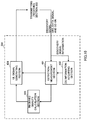
- FIG. 7 is a diagram to show an overall structure of a radio base station 10 according to the present embodiment.
- the radio base station 10 has a plurality of transmitting/receiving antennas 101 for MIMO transmission, amplifying sections 102, transmitting/receiving sections 103, a baseband signal processing section 104, a call processing section 105 and an interface section 106.
- User data to be transmitted from the radio base station 10 to a user terminal 20 through the downlink is input from the higher station apparatus 30, into the baseband signal processing section 104, via the interface section 106.
- a PDCP layer process In the baseband signal processing section 104, a PDCP layer process, division and coupling of the user data, RLC (Radio Link Control) layer transmission processes such as an RLC retransmission control transmission process, MAC (Medium Access Control) retransmission control, including, for example, an HARQ transmission process, scheduling, transport format selection, channel coding, an inverse fast Fourier transform (IFFT) process and a pre-coding process are performed, and the result is transferred to each transmitting/receiving section 103. Furthermore, downlink control signals are also subjected to transmission processes such as channel coding and an inverse fast Fourier transform, and are transferred to each transmitting/receiving section 103.
- RLC Radio Link Control
- MAC Medium Access Control
- Each transmitting/receiving section 103 converts the downlink signals, which are pre-coded and output from the baseband signal processing section 104 on a per antenna basis, into a radio frequency band.
- the amplifying sections 102 amplify the radio frequency signals having been subjected to frequency conversion, and transmit the results through the transmitting/receiving antennas 101.
- radio frequency signals that are received in the transmitting/receiving antennas 101 are each amplified in the amplifying sections 102, converted into baseband signals through frequency conversion in each transmitting/receiving section 103, and input in the baseband signal processing section 104.
- the user data that is included in the input uplink signals is subjected to an FFT process, an IDFT process, error correction decoding, a MAC retransmission control receiving process and RLC layer and PDCP layer receiving processes, and the result is transferred to the higher station apparatus 30 via the interface section 106.
- the call processing section 105 performs call processing such as setting up and releasing communication channels, manages the state of the radio base station 10 and manages the radio resources.
- the interface section 106 transmits and receives signals to and from neighboring radio base stations (backhaul signaling) via an inter-base station interface (for example, optical fiber, X2 interface, etc.). For example, data is transmitted and received between the macro base station 11 and the small base stations 12 via the interface section 106. Alternatively, the interface section 106 transmits and receives signals to and from the higher station apparatus 30 via a predetermined interface.
- an inter-base station interface for example, optical fiber, X2 interface, etc.
- FIG. 8 is a diagram to show a functional structure of a macro base station 11 according to the present embodiment. Note that the following functional structure is formed with the baseband signal processing section 104 provided in the macro base station 11 and so on.
- the macro base station 11 has a UE receiving state acquiring section 301, a received quality calculation section 302, an on/off determining section 303, a scheduler 304, and a DL signal generating section 305.
- the UE receiving state acquiring section 301 acquires information (MR) regarding the receiving state in the user terminal 20 with respect to the detection/measurement signals (discovery signal). Note that an MR is reported from the user terminal 20 that has received a detection/measurement signal (discovery signal) transmitted from a small base station 12. For example, the UE receiving state acquiring section 301 acquires information related to the received power (RSRP) and the received quality (RSRQ) of a detection/measurement signal detected/measured in the user terminal 20, from the user terminal 20 (the above first example).
- RSRP received power
- RSRQ received quality
- the UE receiving state acquiring section 301 acquires the RSSI and the received power (RSRP) of the detection/measurement signal. Also, when the user terminal 20 reports the received SINR of a detection/measurement signal (the above second example), the UE receiving state acquiring section 301 receives the SINR from every user terminal 20.
- RSSI total received power
- RSRP received power
- the received quality calculation section 302 calculates the received quality of each user terminal 20 with respect to the detection/measurement signal based on the information acquired in the UE receiving state acquiring section 301. For example, when information related to the received power (RSRP) of a detection/measurement signal and the total received power (RSSI) of a subframe in which no detection/measurement signal is transmitted is reported from the user terminal 20 (the above variation of the first example 1), the received quality calculation section 302 calculates the received quality (RSRQ) using the RSRP and the RSSI.
- RSRP received power
- RSSI total received power
- the received quality calculation section 302 calculates the received quality (RSRQ) based on the proportion (ratio) of the received power (RSRP) and the value given by adding the received power (RSRP) to the total received power (RSSI).
- the RSRQ that is calculated in the received quality calculation section 302 can be represented by above equation 2.
- the received quality calculation section 302 may generate a new metric by using the RSRP and the RSSI received from the user terminal 20. For example, the received quality calculation section 302 can use above equation 3.
- the result calculated in the received quality calculation section 302 is output to the on/off determining section 303. Note that, if information related to received quality (RSRQ) is directly reported from a user terminal (the above first example), the process in the received quality calculation section 302 can be skipped.
- the on/off determining section 303 controls the small base stations on/off based on the information output from the UE receiving state acquiring section 301 and/or the received quality calculation section 302. For example, the on/off determining section 303 determines to let the small base stations in the off state (DTX state) transition to the on state, and sends a report to the small base station via the interface section 106.
- DTX state off state
- the on/off determining section 303 when there are a plurality of user terminals 20 where the received quality (RSRQ) of a detection/measurement signal is equal to or greater than a predetermined value, the on/off determining section 303 lets the small base station having transmitted the detection/measurement signal transition to the on state.
- the on/off determining section 303 selects, for the user terminals having reported the SINR of the detection/measurement signal, a small base station that has an SINR equal to or higher than a predetermined value and that has a low buffer volume, and has it transition to the on state.
- the scheduler 304 allocates radio resources for DL signals to transmit to the user terminal 20 (scheduling). For example, the scheduler 304 commands the DL signal generating section 305 to generate DS information related to the detection/measurement signals transmitted from small base stations in the DTX state to the user terminals (the signal structure and the transmission time (transmission cycle, transmission period) of the detection/measurement signals, etc.).
- the DL signal generating section 305 generates DL signals based on the command from the scheduler 304. For example, the DL signal generating section 305 generates control signals, data signals, reference signals and so on. Also, the DL signal generating section 305 generates information (DS information) related to the detection/measurement signals transmitted from the small base stations in the DTX state as a higher layer signal or a broadcast signal. The signals generated in the DL signal generating section 305 are transmitted to the user terminal 20 via the transmitting/receiving section 103.
- the UE receiving state acquiring section 301 of the macro base station 11 can acquire the received quality (RSRQ) that is calculated by using the received power measured in a subframe where cell-specific reference signals (CRSs) are transmitted, and the total received power, from the user terminal.
- RSRQ received quality
- CRSs cell-specific reference signals
- a selection section that compares the received quality that is calculated by using the detection/measurement signals and the received quality that is calculated by using the cell-specific reference signals, and selects the cell where the user terminal connects (a macro cell or a small cell) may be further provided in the macro base station 11.
- FIG. 9 is a diagram to show an overall structure of a user terminal 20 according to the present embodiment.
- the user terminal 20 has a plurality of transmitting/receiving antennas 201 for MIMO transmission, amplifying sections 202, transmitting/receiving sections (receiving sections) 203, a baseband signal processing section 204, and an application section 205.
- radio frequency signals that are received in a plurality of transmitting/receiving antennas 201 are each amplified in the amplifying sections 202, and subjected to frequency conversion and converted into baseband signals in the transmitting/receiving sections 203. These baseband signals are subjected to an FFT process, error correction decoding, a retransmission control receiving process and so on, in the baseband signal processing section 204.
- downlink user data is transferred to the application section 205.
- the application section 205 performs processes related to higher layers above the physical layer and the MAC layer, and so on. Also, in the downlink data, broadcast information is also transferred to the application section 205.
- uplink user data is input from the application section 205 into the baseband signal processing section 204.
- the baseband signal processing section 204 performs a retransmission control (H-ARQ (Hybrid ARQ)) transmission process, channel coding, pre-coding, a DFT process, an IFFT process and so on, and transfers the result to each transmitting/receiving section 203.
- the baseband signals that are output from the baseband signal processing section 204 are converted into a radio frequency band in the transmitting/receiving sections 203.
- the amplifying sections 202 amplify the radio frequency signals having been subjected to frequency conversion, and transmit the results from the transmitting/receiving antennas 201.
- FIG. 10 is a principle functional structure diagram of the baseband signal processing section 204 provided in the user terminal 20.
- the baseband signal processing section 204 provided in the user terminal 20 at least has a detection/measurement section 401, a DS information acquiring section 402, a received quality calculation section 403 and a UL signal generating section 404.
- the detection/measurement section 401 detects/measures the DL signals transmitted from the macro base station 11 and/or the small base stations 12. For example, the detection/measurement section 401 measures the received power (RSRP) of a detection/measurement signal transmitted from a small base station in the DTX state in a predetermined subframe, and the total received power (RSSI) of the DL signals in a subframe in which no detection/measurement signal is transmitted. Note that the detection/measurement section 401 can carry out the detection operation efficiently by detecting the detection/measurement signals by using information supplied from the DS information acquiring section 402.
- RSRP received power
- RSSI total received power
- the detection/measurement section 401 may measure the received SINR of the detection/measurement signal (the above second example).
- the DS information acquiring section 402 acquires, from the macro base station 11, DS information related to the detection/measurement signals that are transmitted from small base stations in the DTX state (the signal structure, the transmission time (the transmission cycle and the transmission period) and so on of the detection/measurement signals).
- the DS information acquiring section 402 specifies the transmission time of the detection/measurement signals based on the DS information received from the macro base station 11, and outputs the result to the detection/measurement section 401.
- the received quality calculation section 403 calculates the received quality (RSRQ) using the received power (RSRP) of the detection/measurement signal measured in the detection/measurement section 401 and the total received power (RSSI) of a subframe in which no detection/measurement signal is transmitted. To be more specific, the received quality calculation section 403 calculates the received quality (RSRQ) based on the proportion of the received power (RSRP) and the value given by adding the received power (RSRP) to the total received power (RSSI). At this time, the RSRQ that is calculated in the received quality calculation section 403 can be represented by above equation 2.
- the process in the received quality calculation section 403 can be skipped.
- the UL signal generating section 404 generates information (measurement report) related to the received quality (RSRQ) calculated in the received quality calculation section 403 or the received power (RSRP) measured in the detection/measurement section 401 as an uplink signal. Also, when the total received power (RSSI) itself is transmitted (the above variation of the first example 1), or when the received SINR of the detection/measurement signal is transmitted (the above second example), the UL signal generating section 404 generates information related to the RSSI or the SINR as an uplink signal. Also, the UL signal generating section 404 furthermore generates uplink control signals such as delivery acknowledgement signals, and uplink data signals.
Applications Claiming Priority (3)
| Application Number | Priority Date | Filing Date | Title |
|---|---|---|---|
| JP2013165507 | 2013-08-08 | ||
| JP2014058178A JP6096142B2 (ja) | 2013-08-08 | 2014-03-20 | ユーザ端末、基地局及び無線通信方法 |
| PCT/JP2014/069146 WO2015019825A1 (ja) | 2013-08-08 | 2014-07-18 | ユーザ端末、基地局及び無線通信方法 |
Publications (2)
| Publication Number | Publication Date |
|---|---|
| EP3032890A1 true EP3032890A1 (de) | 2016-06-15 |
| EP3032890A4 EP3032890A4 (de) | 2017-07-05 |
Family
ID=52461164
Family Applications (1)
| Application Number | Title | Priority Date | Filing Date |
|---|---|---|---|
| EP14833978.1A Withdrawn EP3032890A4 (de) | 2013-08-08 | 2014-07-18 | Benutzerendgerät, basisstation und drahtloskommunikationsverfahren |
Country Status (5)
| Country | Link |
|---|---|
| US (1) | US10154479B2 (de) |
| EP (1) | EP3032890A4 (de) |
| JP (1) | JP6096142B2 (de) |
| CN (1) | CN105453663A (de) |
| WO (1) | WO2015019825A1 (de) |
Families Citing this family (13)
| Publication number | Priority date | Publication date | Assignee | Title |
|---|---|---|---|---|
| CN105519174A (zh) * | 2013-09-30 | 2016-04-20 | 富士通株式会社 | 信号测量方法、用户设备以及基站 |
| CN105659694B (zh) | 2013-12-25 | 2020-09-04 | 松下电器(美国)知识产权公司 | 移动台及接收质量测量方法 |
| CN105101282A (zh) * | 2014-05-21 | 2015-11-25 | 中兴通讯股份有限公司 | 发现信号测量的方法、装置及用户终端 |
| TWI692259B (zh) * | 2014-07-16 | 2020-04-21 | 日商新力股份有限公司 | 電信裝置及方法 |
| US10575266B2 (en) * | 2014-07-31 | 2020-02-25 | Nanchang Coolpad Intelligent Technology Company Limited | Method and system for maintaining time-frequency synchronisation, and terminal |
| KR101582598B1 (ko) * | 2014-07-31 | 2016-01-05 | 에스케이텔레콤 주식회사 | 단말장치 및 단말장치의 동작 방법 |
| JP6636038B2 (ja) * | 2015-04-02 | 2020-01-29 | テレフオンアクチーボラゲット エルエム エリクソン(パブル) | リンク品質判定のためのユーザ装置および方法 |
| EP3328117A4 (de) * | 2015-07-22 | 2019-02-13 | Sharp Kabushiki Kaisha | Endgerätevorrichtung, basisstationsvorrichtung, messverfahren und integrierte schaltung |
| EP3329712B1 (de) * | 2015-07-29 | 2022-09-14 | Apple Inc. | Benutzergerät und verfahren zur dynamischen millimeterwellen-stiftzellenkommunikation |
| JP2017063326A (ja) * | 2015-09-24 | 2017-03-30 | 株式会社Nttドコモ | ユーザ端末、無線基地局及び無線通信方法 |
| US10320539B2 (en) * | 2016-05-23 | 2019-06-11 | Nokia Technologies Oy | Methods and apparatuses for reference signal adaptation based on incoming user mobility information |
| CN110392988B (zh) * | 2017-06-29 | 2021-11-16 | Lg电子株式会社 | 测量执行方法和用户设备以及测量配置方法和基站 |
| CN115333655B (zh) * | 2022-10-10 | 2024-03-26 | 华安中云股份有限公司 | 自动检测干扰的方法、装置、背包基站及存储介质 |
Family Cites Families (18)
| Publication number | Priority date | Publication date | Assignee | Title |
|---|---|---|---|---|
| JP4684124B2 (ja) * | 2006-02-16 | 2011-05-18 | 富士通株式会社 | 移動局装置及び同装置における送信電力制御方法 |
| CN102014422A (zh) * | 2009-09-08 | 2011-04-13 | 中兴通讯股份有限公司 | 测量处理方法和装置 |
| KR101676033B1 (ko) * | 2010-01-08 | 2016-11-29 | 삼성전자주식회사 | 무선 통신 시스템에서 기지국의 전력 소모 감소 방법 및 장치 |
| US9161236B2 (en) * | 2010-03-29 | 2015-10-13 | Lg Electronics Inc. | Method and apparatus for measurement for inter-cell interference coordination in radio communication system |
| US9125072B2 (en) * | 2010-04-13 | 2015-09-01 | Qualcomm Incorporated | Heterogeneous network (HetNet) user equipment (UE) radio resource management (RRM) measurements |
| US9609536B2 (en) * | 2010-04-13 | 2017-03-28 | Qualcomm Incorporated | Measurement of received power and received quality in a wireless communication network |
| US9031530B2 (en) | 2010-11-08 | 2015-05-12 | Qualcomm Incorporated | System and method for assisting in powering on sleeping network entities |
| WO2012070823A2 (ko) * | 2010-11-22 | 2012-05-31 | 엘지전자 주식회사 | 무선 통신 시스템에서 하향링크 측정 방법 및 장치 |
| KR20120099568A (ko) * | 2011-01-18 | 2012-09-11 | 삼성전자주식회사 | 무선 통신 시스템에서 단말기 내에 복수 개의 이종 통신 모듈이 있을 경우 간섭을 측정하는 방법 및 장치 |
| JP2014150300A (ja) * | 2011-05-31 | 2014-08-21 | Panasonic Corp | 無線通信端末、無線通信装置及びセル測定方法 |
| KR101896001B1 (ko) * | 2011-07-12 | 2018-09-06 | 한국전자통신연구원 | 이종 네트워크 환경에서 단말의 이동성 관리 방법 |
| WO2013018990A1 (ko) * | 2011-07-29 | 2013-02-07 | 엘지전자 주식회사 | 셀 측정 방법 및 그를 위한 정보 전송 방법 |
| EP3373650B1 (de) * | 2011-08-05 | 2022-11-16 | Panasonic Intellectual Property Corporation of America | Csi-rs rückmeldung in einem koordinierten mehrpunkt-system (comp) |
| US8848560B2 (en) * | 2011-11-04 | 2014-09-30 | Blackberry Limited | Apparatus and method for adaptive transmission during almost blank subframes in a wireless communication network |
| US9509460B2 (en) * | 2012-04-06 | 2016-11-29 | Lg Electronics Inc. | Apparatus for receiving downlink signal in a wireless communication system and method thereof |
| WO2013154382A1 (ko) * | 2012-04-12 | 2013-10-17 | 엘지전자 주식회사 | 무선 통신 시스템에서 간섭 측정 방법 및 장치 |
| CN102752767B (zh) * | 2012-07-02 | 2014-12-10 | 厦门大学 | 一种用多目标遗传算法改善蜂窝小区边缘用户性能的方法 |
| US9526044B2 (en) * | 2013-05-08 | 2016-12-20 | Lg Electronics Inc. | Method of configuring dual connectivity to UE in heterogeneous cell deployment |
-
2014
- 2014-03-20 JP JP2014058178A patent/JP6096142B2/ja active Active
- 2014-07-18 EP EP14833978.1A patent/EP3032890A4/de not_active Withdrawn
- 2014-07-18 CN CN201480045375.8A patent/CN105453663A/zh active Pending
- 2014-07-18 WO PCT/JP2014/069146 patent/WO2015019825A1/ja active Application Filing
- 2014-07-18 US US14/910,318 patent/US10154479B2/en active Active
Non-Patent Citations (1)
| Title |
|---|
| See references of WO2015019825A1 * |
Also Published As
| Publication number | Publication date |
|---|---|
| EP3032890A4 (de) | 2017-07-05 |
| JP6096142B2 (ja) | 2017-03-15 |
| CN105453663A (zh) | 2016-03-30 |
| WO2015019825A1 (ja) | 2015-02-12 |
| JP2015053667A (ja) | 2015-03-19 |
| US10154479B2 (en) | 2018-12-11 |
| US20160192334A1 (en) | 2016-06-30 |
Similar Documents
| Publication | Publication Date | Title |
|---|---|---|
| US10154479B2 (en) | User terminal, base station and radio communication method | |
| US10154430B2 (en) | Radio base station, user terminal and radio communication system | |
| JP6359815B2 (ja) | ユーザ端末、無線基地局及び異周波測定方法 | |
| US9838908B2 (en) | Radio base station, user terminal and radio communication method | |
| EP3051864B1 (de) | Drahtlose basisstation, benutzerendgerät und kommunikationssteuerungsverfahren | |
| JP6399778B2 (ja) | ユーザ端末、基地局、通信システム及び通信方法 | |
| US9888520B2 (en) | User terminal, radio base station and communication control method | |
| US9693291B2 (en) | User terminal, radio base station and communication control method | |
| EP3145263A1 (de) | Funkbasisstation, benutzergerät und funkkommunikationsverfahren | |
| CN106664587A (zh) | 用户终端、无线通信系统以及无线通信方法 | |
| JP6301065B2 (ja) | 無線基地局、ユーザ端末および無線通信方法 | |
| US20200187104A1 (en) | Terminal, radio communication method, and base station | |
| EP2978268A1 (de) | Benutzerendgerät, funkbasisstation und funkkommunikationsverfahren | |
| US20180139725A1 (en) | User terminal, radio base station and radio communication method | |
| EP4149041A1 (de) | Benutzerendgerät und funkkommunikationsverfahren | |
| US9844007B2 (en) | Radio base station, user terminal and radio communication method | |
| EP3522641B1 (de) | Benutzerendgerät und drahtloskommunikationsverfahren | |
| US20160242062A1 (en) | Small base station, user terminal and radio communication method | |
| EP3029982A1 (de) | Basisstation, benutzerendgerät und drahtloskommunikationssteuerungsverfahren |
Legal Events
| Date | Code | Title | Description |
|---|---|---|---|
| PUAI | Public reference made under article 153(3) epc to a published international application that has entered the european phase |
Free format text: ORIGINAL CODE: 0009012 |
|
| 17P | Request for examination filed |
Effective date: 20160222 |
|
| AK | Designated contracting states |
Kind code of ref document: A1 Designated state(s): AL AT BE BG CH CY CZ DE DK EE ES FI FR GB GR HR HU IE IS IT LI LT LU LV MC MK MT NL NO PL PT RO RS SE SI SK SM TR |
|
| AX | Request for extension of the european patent |
Extension state: BA ME |
|
| DAX | Request for extension of the european patent (deleted) | ||
| RIC1 | Information provided on ipc code assigned before grant |
Ipc: H04W 24/10 20090101ALI20170223BHEP Ipc: H04W 84/10 20090101ALI20170223BHEP Ipc: H04W 52/02 20090101AFI20170223BHEP |
|
| A4 | Supplementary search report drawn up and despatched |
Effective date: 20170607 |
|
| RIC1 | Information provided on ipc code assigned before grant |
Ipc: H04W 24/10 20090101ALI20170531BHEP Ipc: H04W 52/02 20090101AFI20170531BHEP Ipc: H04W 84/10 20090101ALI20170531BHEP |
|
| STAA | Information on the status of an ep patent application or granted ep patent |
Free format text: STATUS: THE APPLICATION HAS BEEN WITHDRAWN |
|
| 18W | Application withdrawn |
Effective date: 20190211 |