EP3032146A1 - Seal element - Google Patents
Seal element Download PDFInfo
- Publication number
- EP3032146A1 EP3032146A1 EP15192499.0A EP15192499A EP3032146A1 EP 3032146 A1 EP3032146 A1 EP 3032146A1 EP 15192499 A EP15192499 A EP 15192499A EP 3032146 A1 EP3032146 A1 EP 3032146A1
- Authority
- EP
- European Patent Office
- Prior art keywords
- cavity
- sealing element
- fluidleit
- sealing
- volume
- Prior art date
- Legal status (The legal status is an assumption and is not a legal conclusion. Google has not performed a legal analysis and makes no representation as to the accuracy of the status listed.)
- Withdrawn
Links
Images


Classifications
-
- F—MECHANICAL ENGINEERING; LIGHTING; HEATING; WEAPONS; BLASTING
- F16—ENGINEERING ELEMENTS AND UNITS; GENERAL MEASURES FOR PRODUCING AND MAINTAINING EFFECTIVE FUNCTIONING OF MACHINES OR INSTALLATIONS; THERMAL INSULATION IN GENERAL
- F16J—PISTONS; CYLINDERS; SEALINGS
- F16J15/00—Sealings
- F16J15/02—Sealings between relatively-stationary surfaces
- F16J15/06—Sealings between relatively-stationary surfaces with solid packing compressed between sealing surfaces
- F16J15/068—Sealings between relatively-stationary surfaces with solid packing compressed between sealing surfaces the packing swelling under working conditions
-
- F—MECHANICAL ENGINEERING; LIGHTING; HEATING; WEAPONS; BLASTING
- F16—ENGINEERING ELEMENTS AND UNITS; GENERAL MEASURES FOR PRODUCING AND MAINTAINING EFFECTIVE FUNCTIONING OF MACHINES OR INSTALLATIONS; THERMAL INSULATION IN GENERAL
- F16J—PISTONS; CYLINDERS; SEALINGS
- F16J15/00—Sealings
- F16J15/02—Sealings between relatively-stationary surfaces
- F16J15/06—Sealings between relatively-stationary surfaces with solid packing compressed between sealing surfaces
- F16J15/10—Sealings between relatively-stationary surfaces with solid packing compressed between sealing surfaces with non-metallic packing
- F16J15/104—Sealings between relatively-stationary surfaces with solid packing compressed between sealing surfaces with non-metallic packing characterised by structure
-
- F—MECHANICAL ENGINEERING; LIGHTING; HEATING; WEAPONS; BLASTING
- F16—ENGINEERING ELEMENTS AND UNITS; GENERAL MEASURES FOR PRODUCING AND MAINTAINING EFFECTIVE FUNCTIONING OF MACHINES OR INSTALLATIONS; THERMAL INSULATION IN GENERAL
- F16L—PIPES; JOINTS OR FITTINGS FOR PIPES; SUPPORTS FOR PIPES, CABLES OR PROTECTIVE TUBING; MEANS FOR THERMAL INSULATION IN GENERAL
- F16L13/00—Non-disconnectible pipe-joints, e.g. soldered, adhesive or caulked joints
- F16L13/10—Adhesive or cemented joints
- F16L13/11—Adhesive or cemented joints using materials which fill the space between parts of a joint before hardening
- F16L13/116—Adhesive or cemented joints using materials which fill the space between parts of a joint before hardening for socket pipes
-
- F—MECHANICAL ENGINEERING; LIGHTING; HEATING; WEAPONS; BLASTING
- F16—ENGINEERING ELEMENTS AND UNITS; GENERAL MEASURES FOR PRODUCING AND MAINTAINING EFFECTIVE FUNCTIONING OF MACHINES OR INSTALLATIONS; THERMAL INSULATION IN GENERAL
- F16L—PIPES; JOINTS OR FITTINGS FOR PIPES; SUPPORTS FOR PIPES, CABLES OR PROTECTIVE TUBING; MEANS FOR THERMAL INSULATION IN GENERAL
- F16L21/00—Joints with sleeve or socket
- F16L21/02—Joints with sleeve or socket with elastic sealing rings between pipe and sleeve or between pipe and socket, e.g. with rolling or other prefabricated profiled rings
- F16L21/022—Joints with sleeve or socket with elastic sealing rings between pipe and sleeve or between pipe and socket, e.g. with rolling or other prefabricated profiled rings used with sleeves or nipples for pipes of the same diameter, or with reduction pieces
-
- F—MECHANICAL ENGINEERING; LIGHTING; HEATING; WEAPONS; BLASTING
- F16—ENGINEERING ELEMENTS AND UNITS; GENERAL MEASURES FOR PRODUCING AND MAINTAINING EFFECTIVE FUNCTIONING OF MACHINES OR INSTALLATIONS; THERMAL INSULATION IN GENERAL
- F16L—PIPES; JOINTS OR FITTINGS FOR PIPES; SUPPORTS FOR PIPES, CABLES OR PROTECTIVE TUBING; MEANS FOR THERMAL INSULATION IN GENERAL
- F16L21/00—Joints with sleeve or socket
- F16L21/06—Joints with sleeve or socket with a divided sleeve or ring clamping around the pipe-ends
-
- F—MECHANICAL ENGINEERING; LIGHTING; HEATING; WEAPONS; BLASTING
- F16—ENGINEERING ELEMENTS AND UNITS; GENERAL MEASURES FOR PRODUCING AND MAINTAINING EFFECTIVE FUNCTIONING OF MACHINES OR INSTALLATIONS; THERMAL INSULATION IN GENERAL
- F16L—PIPES; JOINTS OR FITTINGS FOR PIPES; SUPPORTS FOR PIPES, CABLES OR PROTECTIVE TUBING; MEANS FOR THERMAL INSULATION IN GENERAL
- F16L25/00—Constructive types of pipe joints not provided for in groups F16L13/00 - F16L23/00 ; Details of pipe joints not otherwise provided for, e.g. electrically conducting or insulating means
- F16L25/14—Joints for pipes of different diameters or cross-section
Definitions
- the invention relates to a sealing element.
- the invention relates to a connecting device with such a sealing element and a pipe system having a connecting device.
- Sealing members are used in large numbers and in various configurations to fluidly connect fluid conducting or receiving members such as pipes.
- Another object of the present invention is to provide a connecting device comprising such a sealing element.
- a connecting device comprising such a sealing element.
- a pipe system which has a connection device.
- a sealing element which serves for placement on a Fluidleit- or -workelement, in particular for placement on a connecting device for fluid-tight connection of a first Fluidleit- or -effortelements and a second Fluidleit- or -workelements, which serves a Base body having at least one cavity which is without connection to the outside, and wherein the cavity contains an activatable functional agent, which can be converted by an activation process from a first state to a second state, wherein the volume of the cavity during the first state of the functional means V1 is and the volume of the cavity during the second state of the functional means is greater than V1 and V2, so that the body at least partially increases its volume, whereby a sealing effect at least between the body and the Fluidleit- or -abilityelement adjusts, d
- the above task is solved in full.
- the sealing element can be offset from an initially non-sealing state by a AktvsammlungsRIS in a sealing state, wherein it is disposed on a Fluidleit- or -effortelement and unfolds there after activation its sealing effect.
- two cavities are arranged in the base body, wherein at least one cavity contains an activatable functional agent.
- the sealing element can be designed in very different ways, depending on the requirements placed on its sealing function.
- the wall thickness of the sealing element can be selected depending on the prevailing requirements.
- a tailor-made sealing element can be provided which, for example, is particularly suitable for connecting two pipe ends to one another.
- the sealing element also has a holding function by holding the Fluidleit- or -effortelement or to be connected Fluidleit- or -worklusium or supports or fixed in place.
- the wall thickness of the sealing element can be selected depending on the prevailing requirements.
- the wall thickness of the sealing element can be selected so that the increase in volume of the cavity during activation of the functional means directed generates a sealing function, which is oriented towards Fluidleit- or -workelement out. So z. B., the wall thickness of the sealing element, which faces the Fluidleit- or -workelement, be lower than the corresponding opposite side. The expansion of the sealing element initiated by the volume increase of the cavity will therefore preferably take place on the side facing the fluid conducting or receiving element.
- the functional element is fixed to the surface of the cavity in the base body.
- a breakable ampoule is arranged on the surface of the cavity in the body, in which a chemical composition is released, which is released after breaking this ampoule in the cavity and thus the volume of the cavity, for example by reaction with a therein Fabric enlarged.
- the activation process for transferring the activatable functional agent contained in the cavity into the second state is a beat and / or a pressure and / or a current supply and / or an application of microwave radiation and / or an application of ultrasonic waves.
- the functional agent used is an isocyanate and a polyol which has a proportion of water.
- an ampoule with polyol and water is provided, which is damaged, destroyed or at least opened upon activation - for example, by impact or pressure on a trained as a projection on the sealing element element, which has the shape of a rod and can act on the ampoule - so that the isocyanate and the water-containing polyol mix. From these substances forms a polyurethane foam, which occupies a larger volume, as the starting materials. After curing of the polyurethane foam, the increased volume is permanently maintained.
- the ampoule with the water-containing polyol and the isocyanate form the functional agent.
- an ampoule which is arranged in the cavity of the base body such that an activation projection when being hit with a tool in the cavity damages, destroys or at least opens it so that its content coincides mixed in the cavity further functional agent.
- the ampoule is arranged in the cavity and fixed to the surface, that the activation projection when hitting with a tool in the cavity this damaged with certainty and releases their contents.
- the sealing element is designed such that the functional means is fixed to the surface of the cavity in the body, the activation can be made in a defined manner, because thereby the location of the functional agent is predetermined in the cavity, so that the activation there can be effective.
- a cartridge with a compressed gas / foam mixture which hardens after release forms the functional agent.
- the activation can be made by a blow with a tool through which the cartridge releases its contents. After curing of the gas / foam mixture, the increased volume is permanently maintained.
- a swellable polymer material may be provided as a functional agent, which swells under the ingress of water, for example a modified superabsorbent gel. This reacts with water taken up in an ampule which is released by activation in the form of a blow or pressure with a tool.
- a heat-decomposing material which forms a gas and a matrix by means of a current-heated heating wire is also suitable as a functional agent.
- a plug arrangement is provided on the main body, which makes it possible to energize the heating wire, whereby the functional means is heated, thereby decomposing and forms a gas and a curing matrix.
- a device is necessary, which provides the necessary power at the construction site.
- the functional agent is a material composition that transforms under the influence of microwave radiation, increasing its volume.
- a device is necessary, which provides the necessary microwave radiation on the construction site.
- a composition which is converted by the action of ultrasound with an increase in volume is also suitable as a functional agent.
- a device is necessary, which provides the necessary ultrasound on the construction site.
- the activatable functional agent contained in the cavity of the body it is possible to convert the activatable functional agent contained in the cavity of the body from a first state to a second state.
- the volume of the cavity, which is during the first state of the functional means V1 changes and becomes larger.
- the increase in volume comes to an end when the volume of the cavity during the second state of the functional agent is V2.
- the base body at least partially alters its volume, as a result of which a sealing effect is established at least between the base body and the fluid guiding or receiving element, in that at least a portion of the base body comes into contact with the fluid guiding or receiving element.
- the base body has at least one sealing lip which is oriented toward the fluid guiding or receiving element.
- the base body By providing at least one sealing lip on the base body, which is oriented toward the Fluidleit- or -workelement out, it is possible to create a fluid-tight contact of the sealing element on the Fluidleit- or -workelement in a simple manner, if after the activation process, the body be at least partially Volume has increased.
- the number of sealing lips may also be greater than one, preferred embodiments of the sealing element with two, three, four, five, six or more sealing lips.
- the sealing element of the present invention is then formed in a particularly favorable manner, if it is provided that this ring-shaped or disc-shaped or plug-shaped or pillow-shaped or angular, in particular polygonal, is formed.
- a sealing element of the aforementioned forms is suitable in a particularly favorable manner to develop a sealing effect and to adapt to different configurations and dimensions of Fluidleit- or -work instituten.
- a favorable improvement of the present invention is when it is provided that a sealant is arranged on the base body, which swells under water access. Such a sealant swelling up under water ensures that even the slightest leakage through the swelling process, which is accompanied by an increase in the volume of the sealant, is safely stopped.
- the sealing element has a stop on the main body, up to which the Fluidleit- or -workelement on this up or in this is inserted.
- a connecting device can be configured in a very advantageous manner, if it comprises at least one sealing element according to the above description.
- connection device can be used in a simple manner, is safe in terms of the connection of the Fluidleit- or -factieri, has a high density, is simple and inexpensive to provide.
- Such a pipe system is advantageously embodied if it comprises at least one connecting device for the fluid-tight connection of a first fluid guiding or receiving element and a second fluid guiding or receiving element and if the connecting device is designed as described above.
- the sealing element, the connecting device and the pipe system find many uses.
- the sealing element in the recording, conduction, storage and distribution of fluids such as rainwater or sewage / dirty the sealing element, the connecting device and the pipe system is suitable, the requirements for sealing behavior, chemical inertness, longevity and durability, minimized installation costs, low cost and to fulfill another more fully.
- the sealing element can be installed in a simple manner and easily at the designated location and then unfolds the sealing effect by activation. This allows a simple, safe and error-free installation and activation of the sealing element can be made especially under difficult site conditions and in confined spaces.
- sleeves can be equipped with one or with two sealing elements, in order to thus easily connect two pipes to one another in a fluid-tight manner.
- such a seal member may be advantageously received in a sleeve formed at a pipe end to make a fluid-tight connection to the end of a second pipe.
- a memory or a water inlet can be created by such sealing elements are arranged at corresponding sections of the shaft, the memory or the water inlet.
- the sealing member of the present invention can be easily manufactured by a layered structure, wherein the cavity can be produced and provided with the functional means.
- the individual layers can be connected to one another, for example, by gluing, by welding or by a vulcanization process.
- Such a sealing element is thus easy and inexpensive to deploy, it has a high dimensional stability. During storage and transport, appropriate precautions must be taken to ensure that the activation of the functional agent is not inadvertently triggered. This can be realized by a packaging that includes a corresponding protective function.
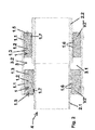
- connection device 4 with two sealing elements 1, 1 is shown in a schematic cross-sectional view.
- the sealing elements 1, 1, which are formed annular, are received in a sleeve 3, which is approximately hollow cylindrical.
- the sealing elements 1, 1 are annular.
- the two sealing elements 1, 1 are designed identically, so that in the following only reference will be made to a sealing element 1.
- the two sealing elements 1, 1 may also be designed differently, so in particular - as far as they are annular - have different inner and / or outer diameter to Fluidleit- or -work institute of different types fluidly connected to each other.
- the sealing element 1 has a main body 1.1.
- the main body 1.1 is formed from an elastomeric material, for example EPDM, a rubber, a thermoplastic elastomer, or a similar material.
- a cavity 1.2 is formed in the main body 1.1.
- the cavity 1.2 in the main body 1.1 of the sealing element 1 is closed to the outside, i. has no connection to the outside.
- a functional agent 1.3 is included in the cavity 1.2 of the main body 1.1.
- the functional agent 1.3 in the cavity 1.2 of the main body 1.1 can be transferred from a first state to a second state.
- an activation projection 1.5 is formed on the main body 1.1 of the sealing element 1, which is formed here as an approximately cylindrical pin.
- the activation projection 1.5 with a tool, for example, with a hammer, hit in the cavity 1.2 of the body 1.1.
- an ampoule is arranged, which is a polyol containing a proportion of water, is added.
- This ampoule is arranged in the cavity 1.2 of the main body 1.1 so that the activation projection 1.5 upon impact with a tool in the cavity 1.2 this damaged, destroyed or at least opens, so that the content is mixed with the present in the cavity 1.2 further functional agent isocyanate 1.3.
- a polyurethane foam is formed, which occupies a larger volume than the starting materials, whereby the volume of the cavity 1.2 increases. Accordingly, the volume of the cavity 1.2 in this second state of the functional means 1.3 is then V2 'or V2 ", where V2' and V2" is greater than V1.
- sealing lips 1.6 are formed, which assign to the fluid guiding or receiving elements 2.1, 2.2 to be connected.
- six sealing lips 1.6 are formed, which extend along the entire inner circumference of the approximately annular sealing element 1.
- the outer circumference of the approximately ring-shaped sealing element 1 is smooth and abuts the inner surface 3.2 of the sleeve 3.
- a sealant 1.7 is additionally arranged, which swells with the addition of water, i. its volume increases. Should there be a leak and water reach the sealant 1.7, this water absorbs, swells up, thereby increasing its volume and seals in addition.
- connecting device 4 shown for the connection of a first Fluidleit- or -effortelements 2.1 with a second Fluidleit- or receiving element 2.2 is provided that the end of the first Fluidleit- or -effortelements 2.1, which is presently designed as a tube, approximately to the middle of Sleeve 3 is inserted in this.
- the second Fluidleit- or -effortelement 2.2 which is presently designed as a tube, also introduced to about the middle of the sleeve 3 in this.
- the two ends of the tubes 2.1, 2.2 abut each other approximately in the middle of the sleeve 3 at the end.
- the first tube 2.1 is dimensioned differently than the second tube 2.2.
- the first tube 2.1 has a substantially smaller wall thickness than the second tube 2.2.
- the first tube 2.1 has a smaller outer diameter than the second tube 2.2.
- the inner diameters of the two tubes 2.1, 2.2 differ only very little and are approximately equal.
- the cavity 1.2 in the main body 1.1 of the sealing element 1 has in this first state of the functional means 1.3, the volume V1.
- FIG. 2 is a schematic cross-section of the connecting device 4 with two sealing elements 1, 1, in which the cavities have the volumes V2 'and V2 "shown.
- the functional means 1.3 located in the cavity 1.2 has been activated. Upon activation, it has moved from the first state to a second state.
- the second state of the functional means 1.3 is associated with the fact that the volume of the cavity 1.2 increases. Accordingly, the volume of the cavity 1.2 in this second state of the functional means 1.3 is now V2 'or V2 ", where V2' and V2" is greater than V1 and V2 'is greater than V2 ".
- an ampoule with water-containing polyol which is arranged in the cavity 1.2 of the body 1.1 so that the activation projection 1.5 when hitting a tool in the cavity 1.2 this damaged, destroyed or at least opens, so that the content with the in the cavity 1.2 further functional agent 1.3 isocyanate mixed.
- a hardening polyurethane foam is formed, which occupies a larger volume than the starting materials, whereby the volume of the cavity 1.2 increases.
- the basic body 1.1 Due to the enlargement of the cavity 1.2 of the basic body 1.1, the basic body 1.1 has at least partially expanded. Since the sealing element 1 is received in the sleeve 3 and is supported on the inner surface 3.2 of the sleeve 3, the increase in volume of the cavity 1.2 acts in the radial direction on the axes of the tubes 2.1, 2.2 such that the sealing lips 1.6 now to the outer surface of the first Pipe 2.1 and the second tube 2.2 are pressed. In this case, the sealing effect of the sealing element 1 unfolds in relation to the first tube 2.1 and the second tube 2.2.
- sealing element 1 is suitable for connecting differently sized tubes 2.1, 2.2 in the connecting device 4 in a fluid-tight manner. Since the sealing element 1 is approximately annular, results in the cylindrical tubes 2.1, 2.2 during expansion of the cavity 1.2 a centering. With respect to their axes.
- the inner diameter of the two tubes 2.1, 2.2 are approximately equal, it is possible to fluid-tightly connect the two tubes 2.1, 2.2 without a significant offset, which brings great advantages in the passage of a fluid through the connecting device with it thereby the flow of the fluid at the junction of the two tubes 2.1, 2.2 is not hindered.
- sealant 1.7 acts sealingly. If this sealant 1.7 can absorb moisture through a slight leakage, it swells, thus increasing its volume, and additionally acts as a sealant.
- Fig. 3 is a schematic sectional side oblique view of the connecting device 4 with two sealing elements 1, 1, in which the cavity 1.2 has the volume V1 according to Fig. 1 shown.
- the sealing element 1 which is approximately annular, rests along its entire circumference on the inner surface 3.2 of the sleeve 3 and can be supported there.
- the sealing lips 1.6 which are each formed in a number of six pieces, are formed along the entire inner circumference of the main body 1.1.
- the two activation projections 1.5, 1.5 are easily accessible for activating the functional means 1.3 accommodated in the cavity 1.2 in order to hammer them into the cavity 1.2 with a tool if the activation of the functional means 1.3 requires this.
- the cavity 1.2 has the volume V1.
- Fig. 4 is a schematic sectional side oblique view of the connecting device 4 with two sealing elements 1, 1, in which the cavities have the volumes V2 'and V2 "in accordance with Fig. 2 shown.
- the cavities 1.2, 1.2 After activation of the functional agent 1.3 in the cavity 1.2 of the main body 1.1 by hammering the activation projection 1.5 into the cavity 1.2, the cavities 1.2, 1.2 have increased to the volumes V2 'and V2 ", in which case the sealing lips 1.6 come to the surface of the first tube 2.1 or the second tube 2.2 in contact and thus create the fluid-tight connection of the two tubes 2.1, 2.2.
- the volumes of the cavities are now V2 'and V2. "In the present case, the volume V2' is greater than the volume V2". Therefore, a larger compression of the sealing element 1 caused by the smaller volume V2 "results on the pipe 2.2 than the compression caused by the larger volume V2 'on the pipe 2.1.
- sealing element 1 instead of two sealing elements 1, 1, as discussed in detail in the previous embodiment, only one sealing element 1 or a sealing element having two sections each having a cavity, wherein the two sections are connected by a web, or a with respect to its dimensions adapted to very different pipe diameter sealing element can be used without this being specified here.
Abstract
Die vorliegende Erfindung betrifft ein Dichtungselement (1) zur Anordnung an einem Fluidleit- oder -aufnahmeelement (2.1), insbesondere zur Anordnung an einer Verbindungsvorrichtung (4) zur fluiddichten Verbindung eines ersten Fluidleit- oder -aufnahmeelements (2.1) und eines zweiten Fluidleit- oder -aufnahmeelements (2.2), das einen Grundkörper (1.1) mit wenigstens einem Hohlraum (1.2) aufweist, welcher ohne Verbindung nach außen ist, und wobei der Hohlraum (1.2) ein aktivierbares Funktionsmittel (1.3) enthält, das durch einen Aktivierungsprozess von einem ersten Zustand in einem zweiten Zustand überführbar ist, wobei das Volumen des Hohlraums (1.2) während des ersten Zustands des Funktionsmittels (1.3) V1 beträgt, und das Volumen des Hohlraums (1.2) während des zweiten Zustands des Funktionsmittels (1.3) größer als V1 ist und V2 beträgt, so dass der Grundkörper (1.1) zumindest teilweise sein Volumen vergrößert, wodurch sich eine Dichtwirkung wenigstens zwischen dem Grundkörper (1.1) und dem Fluidleit- oder -aufnahmeelement (2.1) einstellt.The present invention relates to a sealing element (1) for arrangement on a Fluidleit- or -aufnahmeelement (2.1), in particular for placement on a connecting device (4) for fluid-tight connection of a first Fluidleit- or -aufnahmeelements (2.1) and a second Fluidleit- or receiving element (2.2) having a base body (1.1) with at least one cavity (1.2), which is without connection to the outside, and wherein the cavity (1.2) contains an activatable functional means (1.3), by an activation process of a first State in a second state is convertible, wherein the volume of the cavity (1.2) during the first state of the functional means (1.3) is V1, and the volume of the cavity (1.2) during the second state of the functional means (1.3) is greater than V1 and V2 is, so that the base body (1.1) at least partially increases its volume, resulting in a sealing effect at least between the green dkörper (1.1) and the Fluidleit- or -aufnahmeelement (2.1) adjusts.
Description
Die Erfindung betrifft ein Dichtungselement.The invention relates to a sealing element.
Weiterhin betrifft die Erfindung eine Verbindungsvorrichtung mit einem solchen Dichtungselement und ein Rohrsystem, das eine Verbindungsvorrichtung aufweist.Furthermore, the invention relates to a connecting device with such a sealing element and a pipe system having a connecting device.
Dichtungselemente werden in großer Zahl und in verschiedenen Ausführungen eingesetzt, um Fluidleit- oder -aufnahmeelemente, wie beispielsweise Rohre, fluiddicht miteinander zu verbinden.Sealing members are used in large numbers and in various configurations to fluidly connect fluid conducting or receiving members such as pipes.
Hierbei kommt es häufig vor, dass die zu verbindenden Rohrenden unterschiedliche Maße aufweisen. Es können beispielsweise produktionsbedingt sehr geringe Maßabweichungen auftreten, andererseits können aber auch Maßabweichungen dadurch auftreten, dass ganz unterschiedliche Rohre mit ähnlichen Durchmessern oder solche mit unterschiedlichen Wandstärken miteinander zu verbinden sind.It often happens that the pipe ends to be joined have different dimensions. For example, due to production, very small deviations may occur, but on the other hand dimensional deviations may occur due to the fact that completely different tubes with similar diameters or those with different wall thicknesses are to be connected to one another.
Aus dem Stand der Technik sind hierzu eine Vielzahl von Techniken bekannt, eine solche Verbindung fluiddicht herzustellen. So können beispielsweise an die jeweiligen Maße angepasste Dichtungselemente eingesetzt werden, die den Nachteil aufweisen, dass sie nur für die Rohrgrößen anwendbar sind, für die sie hinsichtlich ihrer Durchmesser ausgelegt sind. Andere Techniken bestehen beispielsweise darin, die zu verbindenden Rohre mittels diese umspannenden Gummimanschetten, die mit Metallbändern und Verschraubungen festgezogen sind, zu sichern.For this purpose, a large number of techniques are known from the prior art for producing such a connection in a fluid-tight manner. Thus, for example, be adapted to the respective dimensions sealing elements are used, which have the disadvantage that they are only applicable to the tube sizes for which they are designed in terms of their diameter. Other techniques include securing the pipes to be joined by means of these rubber grommets tightened with metal straps and fittings.
Hier setzt die Erfindung ein, deren Aufgabe es ist, ein Dichtungselement anzugeben, das die vorstehend genannten Nachteile überwindet, in einfacher Weise installierbar ist, ein hohes Maß an Anpassungsfähigkeit für unterschiedliche Abmessungen von Fluidleit- oder -aufnahmeelementen aufweist, die Fluiddichtheit garantiert und kostengünstig herstellbar ist.This is where the invention, whose object is to provide a sealing element that overcomes the above-mentioned disadvantages, is easy to install, has a high degree of adaptability to different dimensions of Fluidleit- or -aufnahmeelementen, the fluid tightness guaranteed and inexpensive to produce is.
Eine weitere Aufgabe der vorliegenden Erfindung ist es, eine Verbindungsvorrichtung anzugeben, die ein solches Dichtungselement umfasst. Schließlich ist es noch eine Aufgabe der Erfindung, ein Rohrsystem anzugeben, welches eine Verbindungsvorrichtung aufweist.Another object of the present invention is to provide a connecting device comprising such a sealing element. Finally, it is an object of the invention to specify a pipe system which has a connection device.
Die Lösung der ersten Aufgabe erfolgt gemäß den Merkmalen des Anspruchs 1.The solution of the first task is carried out according to the features of
Es hat sich überraschenderweise gezeigt, dass ein Dichtungselement, das zur Anordnung an einem Fluidleit- oder -aufnahmeelement, insbesondere zur Anordnung an einer Verbindungsvorrichtung zur fluiddichten Verbindung eines ersten Fluidleit- oder -aufnahmeelements und eines zweiten Fluidleit- oder -aufnahmeelements, dient, das einen Grundkörper mit wenigstens einem Hohlraum aufweist, welcher ohne Verbindung nach außen ist, und wobei der Hohlraum ein aktivierbares Funktionsmittel enthält, das durch einen Aktivierungsprozess von einem ersten Zustand in einen zweiten Zustand überführbar ist, wobei das Volumen des Hohlraums während des ersten Zustands des Funktionsmittels V1 beträgt und das Volumen des Hohlraums während des zweiten Zustands des Funktionsmittels größer als V1 ist und V2 beträgt, so dass der Grundkörper zumindest teilweise sein Volumen vergrößert, wodurch sich eine Dichtwirkung wenigstens zwischen dem Körper und dem Fluidleit- oder -aufnahmeelement einstellt, die vorstehend genannte Aufgabe vollumfänglich löst.It has surprisingly been found that a sealing element, which serves for placement on a Fluidleit- or -aufnahmeelement, in particular for placement on a connecting device for fluid-tight connection of a first Fluidleit- or -aufnahmeelements and a second Fluidleit- or -aufnahmeelements, which serves a Base body having at least one cavity which is without connection to the outside, and wherein the cavity contains an activatable functional agent, which can be converted by an activation process from a first state to a second state, wherein the volume of the cavity during the first state of the functional means V1 is and the volume of the cavity during the second state of the functional means is greater than V1 and V2, so that the body at least partially increases its volume, whereby a sealing effect at least between the body and the Fluidleit- or -aufnahmeelement adjusts, d The above task is solved in full.
Weitere wichtige Merkmale und Vorteile der Erfindung ergeben sich aus den Unteransprüchen, aus den Fig. und aus der zugehörigen Figurenbeschreibung.Other important features and advantages of the invention will become apparent from the dependent claims, from the Fig. And from the accompanying figure description.
Erfindungsgemäß kann also das Dichtungselement durch einen Aktvierungsprozess von einem zunächst nicht dichtenden Zustand in einen dichtenden Zustand versetzt werden, wobei es an einem Fluidleit- oder -aufnahmeelement angeordnet ist und dort nach Aktivierung seine Dichtwirkung entfaltet.According to the invention, therefore, the sealing element can be offset from an initially non-sealing state by a Aktvierungsprozess in a sealing state, wherein it is disposed on a Fluidleit- or -aufnahmeelement and unfolds there after activation its sealing effect.
In einer bevorzugten Ausführungsart der vorliegenden Erfindung ist vorgesehen, dass zwei Hohlräume im Grundkörper angeordnet sind, wobei wenigstens ein Hohlraum ein aktivierbares Funktionsmittel enthält.In a preferred embodiment of the present invention, it is provided that two cavities are arranged in the base body, wherein at least one cavity contains an activatable functional agent.
Das Dichtungselement kann je nach den Anforderungen, die an seine Dichtfunktion gestellt werden, in sehr unterschiedlicher Weise ausgelegt sein. Hierzu kann die Wandstärke des Dichtungselements je nach den herrschenden Anforderungen gewählt werden.The sealing element can be designed in very different ways, depending on the requirements placed on its sealing function. For this purpose, the wall thickness of the sealing element can be selected depending on the prevailing requirements.
Ebenso ist es möglich, die Anzahl der Hohlräume in dem Grundkörper frei zu wählen, was bedeuten kann, dass zwei, drei, vier oder mehr Hohlräume im Grundkörper angeordnet sind.It is also possible to freely choose the number of cavities in the body, which may mean that two, three, four or more cavities are arranged in the body.
Damit kann ein maßgeschneidertes Dichtungselement bereitgestellt werden, welches beispielsweise in besonders bevorzugter Weise geeignet ist, zwei Rohrenden miteinander zu verbinden.Thus, a tailor-made sealing element can be provided which, for example, is particularly suitable for connecting two pipe ends to one another.
Daneben hat das Dichtungselement auch eine Haltefunktion, indem es das Fluidleit- oder -aufnahmeelement bzw. die zu verbindenden Fluidleit- oder -aufnahmeelemente hält bzw. stützt oder in ihrer Lage fixiert. Auch hierzu kann die Wandstärke des Dichtungselements je nach den herrschenden Anforderungen gewählt werden.In addition, the sealing element also has a holding function by holding the Fluidleit- or -aufnahmeelement or to be connected Fluidleit- or -aufnahmeelemente or supports or fixed in place. Again, the wall thickness of the sealing element can be selected depending on the prevailing requirements.
Insgesamt kann bei der vorliegenden Erfindung die Wandstärke des Dichtungselements so gewählt werden, dass die Volumenzunahme des Hohlraums bei der Aktivierung des Funktionsmittels gerichtet eine Dichtfunktion generiert, die zum Fluidleit- oder -aufnahmeelement hin orientiert ist. So kann z. B. die Wandstärke des Dichtungselements, die dem Fluidleit- oder -aufnahmeelement zugewandt ist, geringer sein, als die entsprechend abgewandte Seite. Die durch die Volumenzunahme des Hohlraums ausgelöste Expansion des Dichtungselements wird daher bevorzugt auf der dem Fluidleit- oder -aufnahmeelement zugewandten Seite stattfinden.Overall, in the present invention, the wall thickness of the sealing element can be selected so that the increase in volume of the cavity during activation of the functional means directed generates a sealing function, which is oriented towards Fluidleit- or -aufnahmeelement out. So z. B., the wall thickness of the sealing element, which faces the Fluidleit- or -aufnahmeelement, be lower than the corresponding opposite side. The expansion of the sealing element initiated by the volume increase of the cavity will therefore preferably take place on the side facing the fluid conducting or receiving element.
In einer sehr günstigen Ausführungsform der vorliegenden Erfindung ist vorgesehen, dass das Funktionselement an der Oberfläche des Hohlraums im Grundkörper festgelegt ist. Durch das Festlegen des Funktionselements an der Oberfläche des Hohlraums im Grundkörper wird in einfacher Weise erreicht, dass der Aktivierungsprozess, der notwendig ist, um das aktivierbare Funktionsmittel von einem ersten Zustand in einen zweiten Zustand zu überführen, in definierter Weise ausführbar ist.In a very favorable embodiment of the present invention it is provided that the functional element is fixed to the surface of the cavity in the base body. By fixing the functional element on the surface of the cavity in the base body is achieved in a simple manner that the activation process, which is necessary to convert the activatable functional agent from a first state to a second state, in a defined manner executable.
Hierzu kann beispielsweise vorgesehen sein, dass an der Oberfläche des Hohlraums im Grundkörper eine zerbrechbare Ampulle angeordnet ist, in der eine chemische Zusammensetzung enthalten ist, die nach Zerbrechen dieser Ampulle im Hohlraum freigesetzt wird und damit das Volumen des Hohlraums beispielsweise durch Reaktion mit einem darin befindlichen Stoff vergrößert.For this purpose, it may be provided, for example, that a breakable ampoule is arranged on the surface of the cavity in the body, in which a chemical composition is released, which is released after breaking this ampoule in the cavity and thus the volume of the cavity, for example by reaction with a therein Fabric enlarged.
In einer bevorzugten Weise ist der Aktvierungsprozess zur Überführung des im Hohlraum enthaltenen aktivierbaren Funktionsmittels in den zweiten Zustand ein Schlag- und / oder ein Druck- und / oder eine Stromzuleitung und / oder eine Beaufschlagung mit Mikrowellenstrahlung und / oder eine Beaufschlagung mit Ultraschallwellen.In a preferred manner, the activation process for transferring the activatable functional agent contained in the cavity into the second state is a beat and / or a pressure and / or a current supply and / or an application of microwave radiation and / or an application of ultrasonic waves.
In sehr vorteilhafter Weise kann vorgesehen sein, dass als Funktionsmittel ein Isocyanat und ein Polyol, das einen Anteil Wasser aufweist einsetzbar sind. Hierzu ist eine Ampulle mit Polyol und Wasser vorgesehen, die bei der Aktivierung - beispielsweise durch Schlag oder Druck auf ein als Vorsprung am Dichtungselement ausgebildetes Element, das die Form eines Stabes aufweist und auf die Ampulle einwirken kann - beschädigt, zerstört oder zumindest geöffnet wird, so dass sich das Isocyanat und das wasserhaltige Polyol vermischen. Aus diesen Stoffen bildet sich ein Polyurethanschaum, der ein größeres Volumen einnimmt, als die Ausgangsstoffe. Nach Aushärten des Polyurethanschaums wird das vergrößerte Volumen dauerhaft aufrechterhalten.In a very advantageous manner it can be provided that the functional agent used is an isocyanate and a polyol which has a proportion of water. For this purpose, an ampoule with polyol and water is provided, which is damaged, destroyed or at least opened upon activation - for example, by impact or pressure on a trained as a projection on the sealing element element, which has the shape of a rod and can act on the ampoule - so that the isocyanate and the water-containing polyol mix. From these substances forms a polyurethane foam, which occupies a larger volume, as the starting materials. After curing of the polyurethane foam, the increased volume is permanently maintained.
Im vorliegenden Erfindungszusammenhang bilden die Ampulle mit dem wasserhaltigen Polyol und das Isocyanat das Funktionsmittel.In the present invention context, the ampoule with the water-containing polyol and the isocyanate form the functional agent.
Ganz besonders bevorzugt ist in diesem Zusammenhang, wenn vorgesehen ist, dass eine Ampulle, die im Hohlraum des Grundkörpers so angeordnet ist, dass ein Aktivierungsvorsprung beim Einschlagen mit einem Werkzeug in den Hohlraum diese beschädigt, zerstört oder zumindest öffnet, so dass deren Inhalt sich mit dem im Hohlraum befindlichen weiteren Funktionsmittel vermischt. Hierzu ist die Ampulle im Hohlraum derartig angeordnet und an der Oberfläche fixiert, dass der Aktivierungsvorsprung beim Einschlagen mit einem Werkzeug in den Hohlraum diese mit Sicherheit beschädigt und deren Inhalt freisetzt.In this context, it is particularly preferred if it is provided that an ampoule which is arranged in the cavity of the base body such that an activation projection when being hit with a tool in the cavity damages, destroys or at least opens it so that its content coincides mixed in the cavity further functional agent. For this purpose, the ampoule is arranged in the cavity and fixed to the surface, that the activation projection when hitting with a tool in the cavity this damaged with certainty and releases their contents.
Durch das Vorsehen, dass das Dichtungselement derart ausgestaltet ist, dass das Funktionsmittel an der Oberfläche des Hohlraums im Grundkörper festgelegt ist, kann die Aktivierung in definierter Weise vorgenommen werden, weil dadurch der Ort des Funktionsmittels im Hohlraum vorgegeben ist, so dass die Aktivierung genau dort wirksam werden kann.By providing that the sealing element is designed such that the functional means is fixed to the surface of the cavity in the body, the activation can be made in a defined manner, because thereby the location of the functional agent is predetermined in the cavity, so that the activation there can be effective.
In einer anderen Ausführung ist vorgesehen dass eine Patrone mit einer komprimierten Gas- / Schaummischung, die nach Freisetzung aushärtet, das Funktionsmittel bildet. Auch hier kann die Aktivierung durch einen Schlag mit einem Werkzeug vorgenommen werden, durch die die Patrone ihren Inhalt freisetzt. Nach Aushärten der Gas- / Schaummischung wird das vergrößerte Volumen dauerhaft aufrechterhalten.In another embodiment, it is provided that a cartridge with a compressed gas / foam mixture which hardens after release forms the functional agent. Again, the activation can be made by a blow with a tool through which the cartridge releases its contents. After curing of the gas / foam mixture, the increased volume is permanently maintained.
In einer weiteren Ausführung kann als Funktionsmittel ein quellfähiges Polymermaterial vorgesehen sein, das unter Wasserzutritt aufquillt, wie beispielsweise ein modifiziertes Superabsorbergel. Dieses reagiert mit Wasser, das in einer Ampulle aufgenommen ist, die durch Aktivierung in Form eines Schlages oder Druckes mit einem Werkzeug freigesetzt wird.In a further embodiment, a swellable polymer material may be provided as a functional agent, which swells under the ingress of water, for example a modified superabsorbent gel. This reacts with water taken up in an ampule which is released by activation in the form of a blow or pressure with a tool.
Auch ein in der Wärme sich zersetzendes Material, das mittels eines bestromten Heizdrahts ein Gas und eine Matrix bildet, ist als Funktionsmittel geeignet. Hierzu ist am Grundkörper eine Steckeranordnung vorgesehen, die es ermöglicht, den Heizdraht zu bestromen, wodurch das Funktionsmittel erwärmt wird, sich dabei zersetzt und ein Gas und eine aushärtende Matrix bildet. Hierzu ist eine Vorrichtung notwendig, die auf der Baustelle den dazu notwendigen Strom zur Verfügung stellt.A heat-decomposing material which forms a gas and a matrix by means of a current-heated heating wire is also suitable as a functional agent. For this purpose, a plug arrangement is provided on the main body, which makes it possible to energize the heating wire, whereby the functional means is heated, thereby decomposing and forms a gas and a curing matrix. For this purpose, a device is necessary, which provides the necessary power at the construction site.
In einer anderen Ausführungsform ist das Funktionsmittel eine unter dem Einfluss von Mikrowellenstrahlung sich umwandelnde Materialzusammensetzung, die ihr Volumen vergrößert. Hierzu ist eine Vorrichtung notwendig, die auf der Baustelle die dazu notwendige Mikrowellenstrahlung zur Verfügung stellt.In another embodiment, the functional agent is a material composition that transforms under the influence of microwave radiation, increasing its volume. For this purpose, a device is necessary, which provides the necessary microwave radiation on the construction site.
Ebenfalls als Funktionsmittel ist eine durch Einwirkung von Ultraschall unter Volumenvergrößerung sich umwandelnde Zusammensetzung geeignet. Hierzu ist eine Vorrichtung notwendig, die auf der Baustelle den dazu notwendigen Ultraschall zur Verfügung stellt.Also suitable as a functional agent is a composition which is converted by the action of ultrasound with an increase in volume. For this purpose, a device is necessary, which provides the necessary ultrasound on the construction site.
Durch die Aktivierungsprozesse, wie vorstehend ausgeführt, gelingt es, das im Hohlraum des Grundkörpers enthaltene aktivierbare Funktionsmittel von einem ersten Zustand in einen zweiten Zustand zu überführen. Hierbei verändert sich das Volumen des Hohlraums, das während des ersten Zustands des Funktionsmittels V1 beträgt und wird größer. Die Volumenvergrößerung findet ein Ende, wenn das Volumen des Hohlraums während des zweiten Zustands des Funktionsmittel V2 beträgt.By the activation processes, as stated above, it is possible to convert the activatable functional agent contained in the cavity of the body from a first state to a second state. Here, the volume of the cavity, which is during the first state of the functional means V1 changes and becomes larger. The increase in volume comes to an end when the volume of the cavity during the second state of the functional agent is V2.
Dadurch verändert der Grundkörper zumindest teilweise sein Volumen, wodurch sich eine Dichtwirkung wenigstens zwischen dem Grundkörper und dem Fluidleit- oder -aufnahmeelement einstellt, indem wenigstens ein Abschnitt des Grundkörpers mit dem Fluidleit- oder -aufnahmeelement in Kontakt kommt.As a result, the base body at least partially alters its volume, as a result of which a sealing effect is established at least between the base body and the fluid guiding or receiving element, in that at least a portion of the base body comes into contact with the fluid guiding or receiving element.
Im Rahmen der vorliegenden Erfindung hat es sich als sehr vorteilhaft herausgestellt, wenn der Grundkörper wenigstens eine Dichtlippe aufweist, die zu dem Fluidleit- oder -aufnahmeelement hin orientiert ist.In the context of the present invention, it has proved to be very advantageous if the base body has at least one sealing lip which is oriented toward the fluid guiding or receiving element.
Durch das Vorsehen wenigstens einer Dichtlippe am Grundkörper, die zu dem Fluidleit- oder -aufnahmeelement hin orientiert ist, gelingt es in einfacher Weise eine fluiddichte Anlage des Dichtungselements an dem Fluidleit- oder -aufnahmeelement zu schaffen, wenn nach dem Aktivierungsprozess der Grundkörper zumindest teilweise sein Volumen vergrößert hat. Je nach den herrschenden Notwendigkeiten kann die Anzahl der Dichtlippen auch größer als eins sein, bevorzugt sind dabei Ausgestaltungen des Dichtungselements mit zwei, drei, vier, fünf, sechs oder mehr Dichtlippen.By providing at least one sealing lip on the base body, which is oriented toward the Fluidleit- or -aufnahmeelement out, it is possible to create a fluid-tight contact of the sealing element on the Fluidleit- or -aufnahmeelement in a simple manner, if after the activation process, the body be at least partially Volume has increased. Depending on the prevailing requirements, the number of sealing lips may also be greater than one, preferred embodiments of the sealing element with two, three, four, five, six or more sealing lips.
Das Dichtungselement der vorliegenden Erfindung ist dann in besonders günstiger Weise ausgebildet, wenn vorgesehen ist, dass dieses ringförmig oder scheibenförmig oder stopfenförmig oder kissenförmig oder eckig, insbesondere vieleckig, ausgebildet ist.The sealing element of the present invention is then formed in a particularly favorable manner, if it is provided that this ring-shaped or disc-shaped or plug-shaped or pillow-shaped or angular, in particular polygonal, is formed.
Ein Dichtungselement der vorgenannten Formen ist in besonders günstiger Weise geeignet, eine Dichtwirkung zu entfalten und sich an unterschiedliche Ausgestaltungen und Abmessungen von Fluidleit- oder -aufnahmeelementen anzupassen.A sealing element of the aforementioned forms is suitable in a particularly favorable manner to develop a sealing effect and to adapt to different configurations and dimensions of Fluidleit- or -aufnahmeelementen.
Eine günstige Verbesserung der vorliegenden Erfindung liegt dann vor, wenn vorgesehen ist, dass am Grundkörper ein Dichtungsmittel angeordnet ist, das unter Wasserzutritt aufquillt. Ein solches unter Wasserzutritt aufquellendes Dichtungsmittel sorgt dafür, dass geringste Leckagen durch den Quellvorgang, der mit einer Volumenvergrößerung des Dichtungsmittels einhergeht, sicher gestoppt werden.A favorable improvement of the present invention is when it is provided that a sealant is arranged on the base body, which swells under water access. Such a sealant swelling up under water ensures that even the slightest leakage through the swelling process, which is accompanied by an increase in the volume of the sealant, is safely stopped.
Hierdurch ergibt sich eine weitere Verbesserung des erfindungsgemäßen Dichtungselements.This results in a further improvement of the sealing element according to the invention.
In einer weiteren günstigen Ausbildungsform der vorliegenden Erfindung ist vorgesehen, dass das Dichtungselement einen Anschlag am Grundkörper aufweist, bis zu dem das Fluidleit- oder -aufnahmeelement auf diesen auf- oder in diesen einschiebbar ist.In a further favorable embodiment of the present invention, it is provided that the sealing element has a stop on the main body, up to which the Fluidleit- or -aufnahmeelement on this up or in this is inserted.
Durch das Vorsehen eines Anschlages am Grundkörper, der das Auf- bzw. Einschieben des Fluidleit- oder -aufnahmeelements begrenzt, kann ein definierter Sitz des Dichtungselements am Fluidleit- oder -aufnahmeelement vorgegeben werden. Dadurch wird nach Aktivierung des aktivierbaren Funktionsmittels ein richtiger Sitz und damit eine hohe Fluiddichtheit in einfacher Weise erreicht.By providing a stop on the base body, which limits the insertion or insertion of the Fluidleit- or -aufnahmeelements, a defined seat of the sealing element can be specified on Fluidleit- or -aufnahmeelement. As a result, a proper seat and thus a high fluid tightness is achieved in a simple manner after activation of the activatable functional means.
Die Lösung der Aufgabe, eine Verbindungsvorrichtung anzugeben, erfolgt gemäß Anspruch 9. Es wurde im Rahmen der vorliegenden Erfindung erkannt, dass eine Verbindungsvorrichtung dann in sehr vorteilhafter Weise ausgestaltbar ist, wenn diese wenigstens ein Dichtungselement gemäß vorstehender Beschreibung umfasst.The solution of the problem to provide a connecting device, is carried out according to claim 9. It has been recognized in the context of the present invention that a connecting device can be configured in a very advantageous manner, if it comprises at least one sealing element according to the above description.
Eine solche Verbindungsvorrichtung kann in einfacher Weise angewendet werden, ist sicher hinsichtlich der Verbindung der Fluidleit- oder -aufnahmeelemente, weist eine hohe Dichtigkeit auf, ist einfach aufgebaut und kostengünstig bereitstellbar.Such a connection device can be used in a simple manner, is safe in terms of the connection of the Fluidleit- or -aufnahmeelemente, has a high density, is simple and inexpensive to provide.
Die Lösung der Aufgabe, ein Rohrsystem mit einer Verbindungsvorrichtung bereitzustellen, erfolgt gemäß Anspruch 10.The solution of the problem to provide a pipe system with a connecting device is carried out according to claim 10.
Ein solches Rohrsystem ist dann in vorteilhafter Weise ausgeführt, wenn es wenigstens eine Verbindungsvorrichtung zur fluiddichten Verbindung eines ersten Fluidleit- oder -aufnahmeelements und eines zweiten Fluidleit- oder -aufnahmeelements umfasst und wenn die Verbindungsvorrichtung wie vorstehend beschrieben ausgestaltet ist.Such a pipe system is advantageously embodied if it comprises at least one connecting device for the fluid-tight connection of a first fluid guiding or receiving element and a second fluid guiding or receiving element and if the connecting device is designed as described above.
Das Dichtungselement, die Verbindungsvorrichtung und das Rohrsystem finden vielfältigen Einsatz. Insbesondere bei der Aufnahme, Leitung, Speicherung und Verteilung von Fluiden, wie Regenwasser oder Schmutz-/Abwasser ist das Dichtungselement, die Verbindungsvorrichtung und das Rohrsystem geeignet, die gestellten Anforderungen hinsichtlich Dichtungsverhalten, chemische Inertheit, Langlebigkeit und Dauerhaftigkeit, minimierten Installationsaufwand, niedrigen Kosten und anderes mehr in vollem Umfang zu erfüllen. Von großem Vorteil ist hierbei, dass das Dichtungselement in einfacher Weise und leicht an dem dafür vorgesehenen Ort installierbar ist und erst dann durch Aktivierung die Dichtungswirkung entfaltet. Hierdurch kann insbesondere unter schwierigen Baustellenbedingungen und bei engen Platzverhältnissen eine einfache, sichere und fehlerfreie Installation und Aktivierung des Dichtungselements vorgenommen werden.The sealing element, the connecting device and the pipe system find many uses. In particular, in the recording, conduction, storage and distribution of fluids such as rainwater or sewage / dirty the sealing element, the connecting device and the pipe system is suitable, the requirements for sealing behavior, chemical inertness, longevity and durability, minimized installation costs, low cost and to fulfill another more fully. Of great advantage here is that the sealing element can be installed in a simple manner and easily at the designated location and then unfolds the sealing effect by activation. This allows a simple, safe and error-free installation and activation of the sealing element can be made especially under difficult site conditions and in confined spaces.
So lassen sich insbesondere Hülsen mit einem oder mit zwei Dichtungselementen ausstatten, um damit in einfacher Weise zwei Rohre miteinander fluiddicht zu verbinden.In particular, sleeves can be equipped with one or with two sealing elements, in order to thus easily connect two pipes to one another in a fluid-tight manner.
Auch kann ein solches Dichtungselement mit Vorteil in einer an einem Rohrende ausgebildeten Muffe aufgenommen sein, um eine fluiddichte Verbindung zum Ende eines zweiten Rohres herzustellen.Also, such a seal member may be advantageously received in a sleeve formed at a pipe end to make a fluid-tight connection to the end of a second pipe.
Ebenso kann so ein Anschluss an einem Schacht, einem Speicher oder einem Wassereinlauf geschaffen werden, indem an entsprechenden Abschnitten des Schachtes, des Speichers bzw. des Wassereinlaufes solche Dichtungselemente angeordnet sind.Likewise, such a connection to a shaft, a memory or a water inlet can be created by such sealing elements are arranged at corresponding sections of the shaft, the memory or the water inlet.
Das Dichtungselement der vorliegenden Erfindung kann in einfacher Weise durch einen schichtweisen Aufbau hergestellt werden, wobei der Hohlraum erzeugt und mit dem Funktionsmittel versehen werden kann. Die einzelnen Schichten können beispielsweise durch Verkleben, durch Verschweißen oder durch einen Vulkanisationsprozess miteinander verbunden sein. Ein solches Dichtungselement ist dadurch einfach und kostengünstig bereitstellbar, es weist eine hohe Maßhaltigkeit auf. Bei der Lagerung und beim Transport sind entsprechende Vorkehrungen zu treffen, dass nicht unbeabsichtigt die Aktivierung des Funktionsmittels ausgelöst wird. Dies kann durch eine Verpackung realisiert werden, die eine entsprechend Schutzfunktion umfasst.The sealing member of the present invention can be easily manufactured by a layered structure, wherein the cavity can be produced and provided with the functional means. The individual layers can be connected to one another, for example, by gluing, by welding or by a vulcanization process. Such a sealing element is thus easy and inexpensive to deploy, it has a high dimensional stability. During storage and transport, appropriate precautions must be taken to ensure that the activation of the functional agent is not inadvertently triggered. This can be realized by a packaging that includes a corresponding protective function.
Es versteht sich, dass die vorstehend genannten und die nachstehend noch zu erläuternden Merkmale nicht nur in der jeweils angegebenen Kombination, sondern auch in anderen Kombinationen oder in Alleinstellung verwendbar sind, ohne den Rahmen der vorliegenden Erfindung zu verlassen.It is understood that the features mentioned above and those yet to be explained below can be used not only in the particular combination given, but also in other combinations or in isolation, without departing from the scope of the present invention.
Bevorzugte Ausführungsbeispiele der Erfindung sind in den Fig. dargestellt und werden in der nachfolgenden Beschreibung näher erläutert, wobei sich gleiche Bezugszeichen auf gleiche oder funktional gleiche oder ähnliche Bauteile beziehen.Preferred embodiments of the invention are shown in the figures and will be explained in more detail in the following description, wherein like reference numerals refer to identical or functionally identical or similar components.
Die Erfindung wird anhand der beigefügten Figuren näher erläutert.The invention will be explained in more detail with reference to the accompanying figures.
Hierzu zeigt:
- Fig. 1
- einen schematischen Querschnitt durch eine Verbindungsvorrichtung mit zwei Dichtungselementen, bei denen der Hohlraum jeweils das Volumen V1 aufweist;
- Fig. 2
- einen schematischen Querschnitt durch eine Verbindungsvorrichtung mit zwei Dichtungselementen, bei denen die Hohlräume die Volumina V2' und V2" aufweisen;
- Fig. 3
- eine schematische geschnittene seitliche Schrägansicht einer Verbindungsvorrichtung mit zwei Dichtungselementen, bei denen der Hohlraum jeweils das Volumen V1 aufweist;
- Fig. 4
- eine schematische geschnittene seitliche Schrägansicht einer Verbindungsvorrichtung mit zwei Dichtungselementen, bei denen die Hohlräume die Volumina V2' und V2" aufweisen.
- Fig. 1
- a schematic cross section through a connecting device with two sealing elements, in which the cavity has the volume V1;
- Fig. 2
- a schematic cross section through a connecting device with two sealing elements, in which the cavities have the volumes V2 'and V2 ";
- Fig. 3
- a schematic cross-sectional side oblique view of a connecting device with two sealing elements, in which the cavity has the volume V1;
- Fig. 4
- a schematic sectional side oblique view of a connecting device with two sealing elements, in which the cavities have the volumes V2 'and V2 ".
In
Die Dichtungselemente 1, 1 sind ringförmig ausgebildet. Die beiden Dichtungselemente 1, 1 sind gleichartig gestaltet, so dass hier im Folgenden nur noch Bezug genommen wird auf ein Dichtungselement 1.The sealing
Es versteht sich dennoch, dass die beiden Dichtungselemente 1, 1 auch unterschiedlich gestaltet sein können, also insbesondere - soweit sie ringförmig ausgebildet sind - unterschiedliche Innen- und / oder Außendurchmesser aufweisen, um Fluidleit- oder -aufnahmeelemente unterschiedlichster Art fluiddicht miteinander verbinden zu können.It is understood, however, that the two sealing
Das Dichtungselement 1 weist einen Grundkörper 1.1 auf. Der Grundkörper 1.1 ist aus einem elastomeren Material, beispielsweise EPDM, einem Gummi, einem thermoplastischem Elastomeren, oder einer ähnlichem Material, gebildet. Im Grundkörper 1.1 ist ein Hohlraum 1.2 ausgebildet. Der Hohlraum 1.2 im Grundkörper 1.1 des Dichtungselements 1 ist nach außen hin abgeschlossen, d.h. weist nach außen hin keine Verbindung auf.The sealing
Im Hohlraum1.2 des Grundkörpers 1.1 ist ein Funktionsmittel 1.3 enthalten. Das Funktionsmittel 1.3 im Hohlraum 1.2 des Grundkörpers 1.1 kann von einem ersten Zustand in einen zweiten Zustand überführt werden. Um dies zu bewerkstelligen ist am Grundkörper 1.1 des Dichtungselements 1 ein Aktivierungsvorsprung 1.5 ausgebildet, der vorliegend als etwa zylindrischer Stift ausgeformt ist. Zur Aktivierung des Funktionsmittels 1.3 im Hohlraum 1.2 des Grundkörpers 1.1 ist der Aktivierungsvorsprung 1.5 mit einem Werkzeug, beispielsweise mit einem Hammer, in den Hohlraum 1.2 des Grundkörpers 1.1 einzuschlagen. In der
Am Grundkörper 1.1 des Dichtungselements 1 sind Dichtlippen 1.6 ausgebildet, die auf die zu verbindenden Fluidleit- oder -aufnahmeelemente 2.1, 2.2 zuweisen. Im vorliegenden Fall sind sechs Dichtlippen 1.6 ausgebildet, die sich entlang des gesamten Innenumfangs des etwa ringförmig ausgebildeten Dichtungselements 1 erstrecken.On the main body 1.1 of the sealing
Der Außenumfang des etwa ringförmig ausgebildeten Dichtungselements 1 ist glatt und liegt an der Innenoberfläche 3.2 der Hülse 3 an. Am Innenumfang des etwa ringförmig ausgebildeten Dichtungselements 1 ist zusätzlich noch ein Dichtungsmittel 1.7 angeordnet, welches unter Hinzutritt von Wasser quillt, d.h. sein Volumen vergrößert. Sollte es zu einer Leckage kommen und Wasser an das Dichtungsmittel 1.7 gelangen, nimmt dieses Wasser auf, quillt auf, vergrößert dabei sein Volumen und dichtet zusätzlich ab.The outer circumference of the approximately ring-shaped
Bei der in
Entsprechend ist das zweite Fluidleit- oder -aufnahmeelement 2.2, das vorliegend als Rohr ausgebildet ist, ebenfalls bis etwa zur Mitte der Hülse 3 in diese eingeführt. Die beiden Enden der Rohre 2.1, 2.2 stoßen etwa in der Mitte der Hülse 3 stirnseitig aneinander an.Accordingly, the second Fluidleit- or -aufnahmeelement 2.2, which is presently designed as a tube, also introduced to about the middle of the
Aus der
Das erste Rohr 2.1 weist einen kleineren Außendurchmesser auf, als das zweite Rohr 2.2. Die Innendurchmesser der beiden Rohre 2.1, 2.2 unterscheiden sich nur sehr wenig und sind annähernd gleich.The first tube 2.1 has a smaller outer diameter than the second tube 2.2. The inner diameters of the two tubes 2.1, 2.2 differ only very little and are approximately equal.
Der Hohlraum 1.2 im Grundkörper 1.1 des Dichtungselement 1 weist in diesem ersten Zustand des Funktionsmittels 1.3 das Volumen V1 auf.The cavity 1.2 in the main body 1.1 of the sealing
In
Die Bezugszeichen entsprechen denen aus
Durch Einschlagen des Aktivierungsvorsprungs 1.5 in den Hohlraum 1.2 im Grundkörper 1.1 des Dichtungselements 1 ist das im Hohlraum 1.2 befindliche Funktionsmittel 1.3 aktiviert worden. Bei der Aktivierung ist es vom ersten Zustand in einen zweiten Zustand übergegangen. Der zweite Zustand des Funktionsmittels 1.3 ist damit verbunden, dass sich das Volumen des Hohlraums 1.2 vergrößert. Dementsprechend ist das Volumen des Hohlraums 1.2 in diesem zweiten Zustand des Funktionsmittels 1.3 nun V2' bzw. V2", wobei V2' und V2" größer als V1 ist und V2' größer als V2" ist.By hammering the activation projection 1.5 in the cavity 1.2 in the main body 1.1 of the sealing
Hierzu eignet sich eine Ampulle mit wasserhaltigen Polyol, die im Hohlraum 1.2 des Grundkörpers 1.1 so angeordnet ist, dass der Aktivierungsvorsprung 1.5 beim Einschlagen mit einem Werkzeug in den Hohlraum 1.2 diese beschädigt, zerstört oder zumindest öffnet, so dass der Inhalt sich mit dem im Hohlraum 1.2 befindlichen weiteren Funktionsmittel 1.3 Isocyanat vermischt. Bei der Reaktion von Isocyanat und wasserhaltigen Polyol entsteht ein aushärtender Polyurethanschaum, der ein größeres Volumen einnimmt, als die Ausgangsmaterialien, wodurch sich das Volumen des Hohlraums 1.2 vergrößert.For this purpose, an ampoule with water-containing polyol, which is arranged in the cavity 1.2 of the body 1.1 so that the activation projection 1.5 when hitting a tool in the cavity 1.2 this damaged, destroyed or at least opens, so that the content with the in the cavity 1.2 further functional agent 1.3 isocyanate mixed. In the reaction of isocyanate and water-containing polyol, a hardening polyurethane foam is formed, which occupies a larger volume than the starting materials, whereby the volume of the cavity 1.2 increases.
Durch die Vergrößerung des Hohlraums 1.2 des Grundkörpers 1.1 hat sich der Grundkörper 1.1 zumindest abschnittsweise ausgedehnt. Da das Dichtungselement 1 in der Hülse 3 aufgenommen ist und sich an der Innenoberfläche 3.2 der Hülse 3 abstützt, wirkt die Volumenvergrößerung des Hohlraums 1.2 in radialer Richtung auf die Achsen der Rohre 2.1, 2.2 derart, dass die Dichtlippen 1.6 nun an die Außenoberfläche des ersten Rohres 2.1 und des zweiten Rohres 2.2 angepresst werden. Hierbei entfaltet sich die Dichtwirkung des Dichtungselements 1 in Bezug auf das erste Rohr 2.1 und das zweite Rohr 2.2.Due to the enlargement of the cavity 1.2 of the basic body 1.1, the basic body 1.1 has at least partially expanded. Since the sealing
Aus der
Da im vorliegenden Fall die Innendurchmesser der beiden Rohre 2.1, 2.2 in etwa gleich sind, gelingt es, die beiden Rohre 2.1, 2.2 ohne einen wesentlichen Versatz fluiddicht miteinander zu verbinden, was große Vorteile beim Leiten eines Fluids durch die Verbindungsvorrichtung mit sich bringt, da dadurch der Fluss des Fluids am Übergang der beiden Rohre 2.1, 2.2 nicht behindert wird.Since in the present case, the inner diameter of the two tubes 2.1, 2.2 are approximately equal, it is possible to fluid-tightly connect the two tubes 2.1, 2.2 without a significant offset, which brings great advantages in the passage of a fluid through the connecting device with it thereby the flow of the fluid at the junction of the two tubes 2.1, 2.2 is not hindered.
Zusätzlich zu den Dichtlippen 1.6 wirkt auch das Dichtungsmittel 1.7 abdichtend. Sollte dieses Dichtmittel 1.7 durch eine geringe Leckage Feuchtigkeit aufnehmen können, quillt dieses, vergrößert auf diese Weise sein Volumen, und wirkt zusätzlich abdichtend.In addition to the sealing lips 1.6 and the sealant 1.7 acts sealingly. If this sealant 1.7 can absorb moisture through a slight leakage, it swells, thus increasing its volume, and additionally acts as a sealant.
In
Die Bezugszeichen entsprechen denen aus
In der
Die Dichtlippen 1.6, die jeweils in einer Anzahl von sechs Stück ausgebildet sind, sind entlang des gesamten Innenumfangs des Grundkörpers 1.1 ausgebildet.The sealing lips 1.6, which are each formed in a number of six pieces, are formed along the entire inner circumference of the main body 1.1.
Die beiden Aktivierungsvorsprünge 1.5, 1.5 sind zur Aktivierung des im Hohlraum 1.2 aufgenommenen Funktionsmittels 1.3 leicht zugänglich, um diese mit einem Werkzeug in den Hohlraum 1.2 einzuschlagen, wenn die Aktivierung des Funktionsmittel 1.3 dies erfordert. Der Hohlraum 1.2 weist das Volumen V1 auf.The two activation projections 1.5, 1.5 are easily accessible for activating the functional means 1.3 accommodated in the cavity 1.2 in order to hammer them into the cavity 1.2 with a tool if the activation of the functional means 1.3 requires this. The cavity 1.2 has the volume V1.
In
Die Bezugszeichen entsprechen denen aus
Nach Aktivierung des Funktionsmittels 1.3 im Hohlraum 1.2 des Grundkörpers 1.1 durch Einschlagen des Aktivierungsvorsprungs 1.5 in den Hohlraum 1.2 haben sich die Hohlräume 1.2, 1.2 auf die Volumina V2' bzw. V2" vergrößert. Hierbei kommen die Dichtlippen 1.6 mit der Oberfläche des ersten Rohres 2.1 bzw. des zweiten Rohres 2.2 in Berührung und schaffen so die fluiddichte Verbindung der beiden Rohre 2.1, 2.2.After activation of the functional agent 1.3 in the cavity 1.2 of the main body 1.1 by hammering the activation projection 1.5 into the cavity 1.2, the cavities 1.2, 1.2 have increased to the volumes V2 'and V2 ", in which case the sealing lips 1.6 come to the surface of the first tube 2.1 or the second tube 2.2 in contact and thus create the fluid-tight connection of the two tubes 2.1, 2.2.
Die Volumina der Hohlräume betragen nun V2' und V2". Im vorliegenden Fall ist das Volumen V2' größer als das Volumen V2". Es ergibt sich daher eine durch das kleinere Volumen V2" hervorgerufene größere Kompression des Dichtungselements 1 auf das Rohr 2.2, als die durch das größere Volumen V2'auf das Rohr 2.1 bewirkte Kompression.The volumes of the cavities are now V2 'and V2. "In the present case, the volume V2' is greater than the volume V2". Therefore, a larger compression of the sealing
Es ist leicht zu erkennen, dass die Maßunterschiede der beiden Rohre 2.1, 2.2 durch unterschiedliche Volumina V2' und V2" der Hohlräume 1.2 der beiden Grundkörper 1.1 ausgeglichen werden. Der Freiraum 3.1 an der Stoßstelle der beiden Rohr 2.1, 2.2 in der Hülse 3 ist dadurch abgedichtet, dass sich die Außenseiten der beiden ringförmig ausgebildeten Dichtungselemente 1, 1 an der Innenoberfläche 3.2 der Hülse 3 anlegen und durch den expandierten Hohlraum 1.2 an diese Innenoberfläche gedrückt werden.It is easy to see that the dimensional differences of the two tubes 2.1, 2.2 are compensated by different volumes V2 'and V2 "of the cavities 1.2 of the two basic bodies 1.1 The clearance 3.1 is at the junction of the two tubes 2.1, 2.2 in the
Es ist leicht nachvollziehbar, dass anstelle von zwei Dichtungselementen 1, 1, wie im vorstehenden Ausführungsbeispiel detailliert diskutiert, auch nur ein Dichtungselement 1 oder ein Dichtungselement, das zwei Abschnitte mit je einem Hohlraum aufweist, wobei die zwei Abschnitte durch einen Steg verbunden sind, oder ein hinsichtlich seiner Maße an sehr unterschiedliche Rohrdurchmesser angepasstes Dichtungselement zum Einsatz kommen kann, ohne dass dies hier näher ausgeführt ist.It is easily understood that instead of two sealing
Auch kann - was hier nicht explizit gezeigt ist - die Hülse an ihren beiden Enden, in die die Fluidleit- oder -aufnahmeelemente einsteckbar sind, unterschiedliche Formen, oder für den Fall, dass deren Querschnitt rund ausgebildet ist, unterschiedliche Durchmesser aufweisen, um je nach den auszuführenden Verbindungen unterschiedlich bemessene Fluidleit- oder -aufnahmeelemente aufzunehmen.Also, which is not explicitly shown here - the sleeve at its two ends, in which the Fluidleit- or -aufnahmeelemente are inserted, different shapes, or in the case that the cross-section is round, have different diameters, to accommodate differently sized fluid conducting or receiving elements depending on the connections to be made.
- 11
- Dichtungselementsealing element
- 1.11.1
- Grundkörperbody
- 1.21.2
- Hohlraumcavity
- 1.31.3
- FunktionsmittelWorking medium
- 1.41.4
- Oberflächesurface
- 1.51.5
- Aktivierungsvorsprungactivation edge
- 1.61.6
- Dichtlippesealing lip
- 1.71.7
- Dichtungsmittelsealant
- 2.12.1
- erstes Fluidleit- oder -aufnahmeelementfirst Fluidleit- or -aufnahmeelement
- 2.22.2
- zweites Fluidleit- oder -aufnahmeelementsecond fluid guiding or receiving element
- 33
- Hülseshell
- 3.13.1
- Freiraumfree space
- 3.23.2
- Innenoberflächeinner surface
- 44
- Verbindungsvorrichtungconnecting device
- V1V1
- Volumenvolume
- V2V2
- Volumenvolume
- V2'V2 '
- Volumenvolume
- V2"V2 "
- Volumenvolume
Claims (10)
Applications Claiming Priority (1)
| Application Number | Priority Date | Filing Date | Title |
|---|---|---|---|
| DE202014106004.9U DE202014106004U1 (en) | 2014-12-12 | 2014-12-12 | sealing element |
Publications (1)
| Publication Number | Publication Date |
|---|---|
| EP3032146A1 true EP3032146A1 (en) | 2016-06-15 |
Family
ID=54365118
Family Applications (1)
| Application Number | Title | Priority Date | Filing Date |
|---|---|---|---|
| EP15192499.0A Withdrawn EP3032146A1 (en) | 2014-12-12 | 2015-11-02 | Seal element |
Country Status (2)
| Country | Link |
|---|---|
| EP (1) | EP3032146A1 (en) |
| DE (1) | DE202014106004U1 (en) |
Cited By (3)
| Publication number | Priority date | Publication date | Assignee | Title |
|---|---|---|---|---|
| WO2018002608A1 (en) * | 2016-06-30 | 2018-01-04 | Acorn Intellectual Properties Ltd | Coupling for forming a sealed joint between first and second tubular members |
| CN110219985A (en) * | 2018-03-02 | 2019-09-10 | 烟台冰轮医药装备有限公司 | A kind of sealing ring and sealing mechanism, vacuum freeze drier with the sealing ring |
| EP4180116A1 (en) * | 2021-11-10 | 2023-05-17 | B. Braun Avitum AG | Sealing adapter with a contour sealing element for adapting filter assembly for a functional test of hollow fibre filter modules |
Citations (4)
| Publication number | Priority date | Publication date | Assignee | Title |
|---|---|---|---|---|
| DE2457557A1 (en) * | 1974-12-05 | 1976-06-10 | Passavant Werke | CONNECTION FOR SLEEVED PIPES IN PARTICULAR |
| US5096206A (en) * | 1990-06-01 | 1992-03-17 | W. E. Hall Company | Pipe joint sealer |
| DE10315801A1 (en) * | 2003-03-28 | 2004-10-14 | Pt-Poly-Tec Gmbh Vertrieb Und Herstellung Von Dichtungssystemen | Method and sealing element for sealing pipe and sewer systems, pipe penetrations, buildings and the like. |
| US7011315B2 (en) * | 2000-03-14 | 2006-03-14 | L&L Products, Inc. | Expandable pre-formed plug |
Family Cites Families (11)
| Publication number | Priority date | Publication date | Assignee | Title |
|---|---|---|---|---|
| DE403576C (en) * | 1921-08-31 | 1924-10-01 | John Hetherington | Seal for liquid and gas lines and containers |
| DE3539595A1 (en) * | 1985-11-08 | 1987-05-14 | Hanseatische Isoliermittel Gmb | Sealing rings having an insert of water-swellable plastic |
| FI892915A (en) * | 1989-08-30 | 1990-12-15 | Uponor Nv | TAETNINGSRING FOER MUFFOERBINDNING OCH FOERFARANDE FOER AOSTADKOMMANDE AV MUFFOERBINDNING. |
| GB2273537B (en) * | 1992-12-17 | 1996-01-31 | Yong Goo Shin | Ring packing |
| DE19617437A1 (en) * | 1996-05-02 | 1997-11-06 | Hermann Muecher Gmbh | Elastomeric ring seal for use e.g. in collar fitting floor hole |
| JPH10273646A (en) * | 1997-03-28 | 1998-10-13 | Nichias Corp | Material for foamed rubber coated gasket |
| DE19945157C1 (en) * | 1999-09-21 | 2001-07-12 | Fraunhofer Ges Forschung | Seals for pipe connections |
| AU2001282062A1 (en) * | 2000-09-13 | 2002-03-26 | Fitr Gesellschaft Fur Innovation Im Tief- Und Rohrleitungsbau Weimar M.b.H. | Sealing system |
| US20050161886A1 (en) * | 2004-01-28 | 2005-07-28 | Berry David H. | Heat-activated expandable seal and method for producing same |
| DE202008005936U1 (en) * | 2008-04-29 | 2009-09-03 | Pt-Poly-Tec Gmbh Vertrieb Und Herstellung Von Dichtungssystemen | Coupling for connecting two pipe ends with secondary source seal |
| DE102010032199B3 (en) * | 2010-07-26 | 2011-12-15 | Gummi- und Kunststofftechnik Fürstenwalde GmbH | Sealing ring for screwed connection of left and right sleeve pipes, has outer and inner rings and integrated element made of swellable materials and integrated into rubber parts, so that sealing function is formed due to increase in volume |
-
2014
- 2014-12-12 DE DE202014106004.9U patent/DE202014106004U1/en not_active Expired - Lifetime
-
2015
- 2015-11-02 EP EP15192499.0A patent/EP3032146A1/en not_active Withdrawn
Patent Citations (4)
| Publication number | Priority date | Publication date | Assignee | Title |
|---|---|---|---|---|
| DE2457557A1 (en) * | 1974-12-05 | 1976-06-10 | Passavant Werke | CONNECTION FOR SLEEVED PIPES IN PARTICULAR |
| US5096206A (en) * | 1990-06-01 | 1992-03-17 | W. E. Hall Company | Pipe joint sealer |
| US7011315B2 (en) * | 2000-03-14 | 2006-03-14 | L&L Products, Inc. | Expandable pre-formed plug |
| DE10315801A1 (en) * | 2003-03-28 | 2004-10-14 | Pt-Poly-Tec Gmbh Vertrieb Und Herstellung Von Dichtungssystemen | Method and sealing element for sealing pipe and sewer systems, pipe penetrations, buildings and the like. |
Cited By (4)
| Publication number | Priority date | Publication date | Assignee | Title |
|---|---|---|---|---|
| WO2018002608A1 (en) * | 2016-06-30 | 2018-01-04 | Acorn Intellectual Properties Ltd | Coupling for forming a sealed joint between first and second tubular members |
| US11255472B2 (en) | 2016-06-30 | 2022-02-22 | Acorn Intellectual Properties Ltd | Coupling for forming a sealed joint between first and second tubular members |
| CN110219985A (en) * | 2018-03-02 | 2019-09-10 | 烟台冰轮医药装备有限公司 | A kind of sealing ring and sealing mechanism, vacuum freeze drier with the sealing ring |
| EP4180116A1 (en) * | 2021-11-10 | 2023-05-17 | B. Braun Avitum AG | Sealing adapter with a contour sealing element for adapting filter assembly for a functional test of hollow fibre filter modules |
Also Published As
| Publication number | Publication date |
|---|---|
| DE202014106004U1 (en) | 2016-03-17 |
Similar Documents
| Publication | Publication Date | Title |
|---|---|---|
| DE3414180A1 (en) | Sealing device for abutting components which are at least approximately pipe-shaped, in particular for concrete mouldings | |
| DE2832614A1 (en) | CONNECTING PIECE FOR PIPING | |
| DE3317061A1 (en) | FLANGE JOINT ARRANGEMENT | |
| EP2990711B1 (en) | Housing assembly for a pipe connection and method for protection of pipe joints | |
| EP3032146A1 (en) | Seal element | |
| EP2177810B1 (en) | Plug for sealing a pipe | |
| WO2001081807A1 (en) | Device for sealing an annulus delimited by an inner body and outer body | |
| DE3436254C2 (en) | Method and seal for connecting pipe ends of a gas line that has already been used | |
| EP1361380A2 (en) | Sealing arrangement | |
| DE202017101503U1 (en) | Screwable branch for an uneven sewage pipe | |
| DE1956737A1 (en) | Device for connecting and sealing pipes | |
| EP3146156B1 (en) | Protective element with drainage, for connecting to a concrete element of a tunnel extension | |
| DE2251082B2 (en) | Tensile connection of two sewer pipes | |
| DE202007018296U1 (en) | Sealing system for pipe and cable bushings | |
| WO2000015995A1 (en) | Fitting for a fluid-carrying pipe | |
| DE2429218A1 (en) | PIPE CONNECTION WITH SEAL | |
| EP1927804B1 (en) | Pipe connection | |
| DE102008050073A1 (en) | Connector for connecting ends of corrugated pipe, has groove-like recess provided in overlapping area of pipe end, and safety device arranged at groove-like recess of mounting hole, where safety device is provided as end-firm structure | |
| DE1033974B (en) | Line connection for high pressure hoses | |
| DE1475890B2 (en) | Socket pipe seal | |
| DE3706216C2 (en) | ||
| DE4242236C1 (en) | Wall-box for polyethylene@ pipe - has annular space between pipe and protective tube filled with polyurethane-based plastic sealant | |
| DE3820802C1 (en) | ||
| DE102009003502A1 (en) | Bush bearing for a motor vehicle, with hydraulic damping, has a prestressed rubber carrier body to bond the inner anchor and outer tube together | |
| EP0392148B1 (en) | Pipe connection |
Legal Events
| Date | Code | Title | Description |
|---|---|---|---|
| PUAI | Public reference made under article 153(3) epc to a published international application that has entered the european phase |
Free format text: ORIGINAL CODE: 0009012 |
|
| AK | Designated contracting states |
Kind code of ref document: A1 Designated state(s): AL AT BE BG CH CY CZ DE DK EE ES FI FR GB GR HR HU IE IS IT LI LT LU LV MC MK MT NL NO PL PT RO RS SE SI SK SM TR |
|
| AX | Request for extension of the european patent |
Extension state: BA ME |
|
| STAA | Information on the status of an ep patent application or granted ep patent |
Free format text: STATUS: THE APPLICATION IS DEEMED TO BE WITHDRAWN |
|
| 18D | Application deemed to be withdrawn |
Effective date: 20161216 |