EP3032107A2 - Turbomolecular pump - Google Patents
Turbomolecular pump Download PDFInfo
- Publication number
- EP3032107A2 EP3032107A2 EP15191438.9A EP15191438A EP3032107A2 EP 3032107 A2 EP3032107 A2 EP 3032107A2 EP 15191438 A EP15191438 A EP 15191438A EP 3032107 A2 EP3032107 A2 EP 3032107A2
- Authority
- EP
- European Patent Office
- Prior art keywords
- rotor
- pump
- stator
- turbomolecular
- blade
- Prior art date
- Legal status (The legal status is an assumption and is not a legal conclusion. Google has not performed a legal analysis and makes no representation as to the accuracy of the status listed.)
- Granted
Links
- 238000005086 pumping Methods 0.000 claims abstract description 49
- 125000006850 spacer group Chemical group 0.000 claims description 17
- 239000002245 particle Substances 0.000 description 20
- 230000006835 compression Effects 0.000 description 3
- 238000007906 compression Methods 0.000 description 3
- 238000005096 rolling process Methods 0.000 description 3
- 230000003068 static effect Effects 0.000 description 3
- IJGRMHOSHXDMSA-UHFFFAOYSA-N Atomic nitrogen Chemical compound N#N IJGRMHOSHXDMSA-UHFFFAOYSA-N 0.000 description 2
- 230000001419 dependent effect Effects 0.000 description 2
- 238000011161 development Methods 0.000 description 2
- 230000018109 developmental process Effects 0.000 description 2
- 238000010586 diagram Methods 0.000 description 2
- 238000003801 milling Methods 0.000 description 2
- 230000001154 acute effect Effects 0.000 description 1
- 230000006978 adaptation Effects 0.000 description 1
- 230000004323 axial length Effects 0.000 description 1
- 230000005540 biological transmission Effects 0.000 description 1
- 238000005266 casting Methods 0.000 description 1
- 238000010276 construction Methods 0.000 description 1
- 238000013461 design Methods 0.000 description 1
- 238000009826 distribution Methods 0.000 description 1
- 230000000694 effects Effects 0.000 description 1
- 239000007789 gas Substances 0.000 description 1
- 238000007373 indentation Methods 0.000 description 1
- 238000003780 insertion Methods 0.000 description 1
- 230000037431 insertion Effects 0.000 description 1
- 238000004519 manufacturing process Methods 0.000 description 1
- 229910052757 nitrogen Inorganic materials 0.000 description 1
- 238000012797 qualification Methods 0.000 description 1
- 238000011160 research Methods 0.000 description 1
- 239000004065 semiconductor Substances 0.000 description 1
- 238000004088 simulation Methods 0.000 description 1
Images


Classifications
-
- F—MECHANICAL ENGINEERING; LIGHTING; HEATING; WEAPONS; BLASTING
- F04—POSITIVE - DISPLACEMENT MACHINES FOR LIQUIDS; PUMPS FOR LIQUIDS OR ELASTIC FLUIDS
- F04D—NON-POSITIVE-DISPLACEMENT PUMPS
- F04D19/00—Axial-flow pumps
- F04D19/02—Multi-stage pumps
- F04D19/04—Multi-stage pumps specially adapted to the production of a high vacuum, e.g. molecular pumps
- F04D19/042—Turbomolecular vacuum pumps
-
- F—MECHANICAL ENGINEERING; LIGHTING; HEATING; WEAPONS; BLASTING
- F04—POSITIVE - DISPLACEMENT MACHINES FOR LIQUIDS; PUMPS FOR LIQUIDS OR ELASTIC FLUIDS
- F04D—NON-POSITIVE-DISPLACEMENT PUMPS
- F04D19/00—Axial-flow pumps
- F04D19/02—Multi-stage pumps
- F04D19/04—Multi-stage pumps specially adapted to the production of a high vacuum, e.g. molecular pumps
- F04D19/044—Holweck-type pumps
-
- F—MECHANICAL ENGINEERING; LIGHTING; HEATING; WEAPONS; BLASTING
- F04—POSITIVE - DISPLACEMENT MACHINES FOR LIQUIDS; PUMPS FOR LIQUIDS OR ELASTIC FLUIDS
- F04D—NON-POSITIVE-DISPLACEMENT PUMPS
- F04D29/00—Details, component parts, or accessories
- F04D29/40—Casings; Connections of working fluid
- F04D29/52—Casings; Connections of working fluid for axial pumps
- F04D29/522—Casings; Connections of working fluid for axial pumps especially adapted for elastic fluid pumps
- F04D29/526—Details of the casing section radially opposing blade tips
-
- F—MECHANICAL ENGINEERING; LIGHTING; HEATING; WEAPONS; BLASTING
- F04—POSITIVE - DISPLACEMENT MACHINES FOR LIQUIDS; PUMPS FOR LIQUIDS OR ELASTIC FLUIDS
- F04D—NON-POSITIVE-DISPLACEMENT PUMPS
- F04D29/00—Details, component parts, or accessories
- F04D29/66—Combating cavitation, whirls, noise, vibration or the like; Balancing
- F04D29/68—Combating cavitation, whirls, noise, vibration or the like; Balancing by influencing boundary layers
- F04D29/681—Combating cavitation, whirls, noise, vibration or the like; Balancing by influencing boundary layers especially adapted for elastic fluid pumps
- F04D29/685—Inducing localised fluid recirculation in the stator-rotor interface
Definitions
- the invention relates to a turbomolecular pump having at least one turbomolecular pump stage, which comprises at least one blade rotor rotatably mounted about an axis.
- turbomolecular pumps are basically known and are known e.g. used in the semiconductor industry and in physical research to generate a high vacuum needed there.
- the turbomolecular pump is characterized by a blade rotor, also referred to below as a rotor, whose structure is reminiscent of the rotor of a turbine.
- the blade rotor interacts with a blade stator, also referred to below as a stator, and usually rotates at such a high speed that the tangential velocity of the individual rotor blades is of a similar magnitude to the mean thermal velocity of particles to be conveyed.
- a vertical pumping direction from top to bottom, the majority of the particles collide with a bottom surface of an angularly pitched rotor blade.
- By a preferred direction of the bottom of the rotor blade in the pumping direction creates a pumping action.
- the rotor must also be surrounded by a wall to prevent backflow of the particles outside the rotor area.
- a wall is formed, for example, from the inside of a housing containing the turbomolecular pumping stage or from the insides of stator stator rings arranged between individual stator disks.
- This wall has a cylindrical inner surface, which is arranged concentrically to the rotor and whose preferred direction points radially inward and thus in the pumping direction. Particles that by themselves or after colliding with a rotor blade on the cylindrical inner surface of the wall meet there no pumping action more.
- a turbomolecular pump with the features of claim 1, and in particular in that a wall at least partially surrounding the blade rotor is provided on at least one pump effective portion of its blade rotor side facing with at least one recess.
- the performance of the turbomolecular pump can be improved by giving particles which hit the wall a preferred direction in the pumping direction.
- a such depression can be easily introduced, for example, with an ordinary milling tool.
- turbomolecular pump enables the technical adaptation of a static component of the turbomolecular pump. Static components are not exposed to such high mechanical loads as rotor components. They can therefore be modified and installed without qualification. For this reason, further developments of turbomolecular pumps are particularly advantageous in terms of development if they merely relate to static components, as is possible according to the invention here.
- the pumping action is further improved if the depression has a course with an axial component and / or with a non-zero pitch. As a result, the particles are given a preferential direction, likewise with an axial component. The pumping action in the axial direction is thus improved.
- the recess may have a spiral or helical course.
- the recess may thus have a thread profile corresponding to the recess profile in Gaede'sche screw pumps or molecular pumps according to Holweck.
- the depression may be formed as a helix. As a result, the particles are taught even more uniformly the desired preferred direction.
- the spiral or helical course of the depression advantageously has the same direction of rotation as the blade rotor.
- the recess may also be formed groove or channel-like.
- the guidance of the particles in their preferred direction is thereby further improved.
- Such a groove or channel can be particularly easily introduced into a wall inside.
- the pump-effective portion is further provided with a plurality of, in particular unrelated, depressions.
- the depressions can advantageously extend parallel to one another.
- the pump-effective portion of the wall is designed as Holweckstator. So can be applied to a Turbomolekularpumptreatment with a few design measures of the known Holweckstator.
- the wall may advantageously be formed by a housing surrounding the blade rotor.
- the pump-effective portion is formed on the inside of the housing. This does not require an additional wall to be introduced into the pump housing.
- the recess can also be produced by casting casings or by milling.
- the housing may be the outer housing of the pump. As a result, even fewer items are needed.
- the wall may also be formed, for example, by a ring element surrounding the blade rotor and the pump-effective partial region may be formed on the inside of the ring element.
- the ring element is easy to machine and assemble, but constitutes an additional part of the vacuum pump.
- the ring element may be designed to be arranged between two stator disks and thus fix their axial distance between each other.
- the ring element may in particular be a spacer ring, a spacer ring, a spacer sleeve and / or a spacer sleeve.
- the blade rotor comprises a plurality of axially successively arranged, integrally connected or separate rotor disks.
- the pumping power of the turbomolecular pump can be further improved by a plurality of rotor disks.
- the pump-effective portion extends in the axial direction only over a, preferably the suction side of the pump nearest rotor disk comprehensive, subset of rotor disks, in particular over exactly one rotor disk.
- the pumping effect can be improved particularly effectively by the recess according to the invention.
- At least some blades of a blade stator cooperating with the blade rotor may be connected to the wall. This results in a simpler construction of the turbomolecular pump.
- the pump-effective portion can advantageously be located axially outside of blades of a blade stator interacting with the blade rotor.
- the pump-effective portion is then arranged only with respect to the blades of the blade rotor, that is not at the height of the stator.
- a pump-effective region of the wall may extend at least substantially over the entire axial length of the turbomolecular pump.
- a blade stator interacting with the blade rotor comprises a plurality of stator disks arranged axially one after the other, wherein the pump-effective portion is only axially between the stator disks and / or axially adjacent to at least one of the stator disks.
- the pump-effective portion may be formed by the inner sides of each of stator disks and thus located at the height of a rotor disk stator spacer rings. This facilitates the insertion of the recess.
- blades of a blade stator interacting with the blade rotor have in each case an angle of attack in a radially outer end region which is at least approximately equal to a pitch of the recess.
- the recess extends at least substantially parallel to the orientation or to the angle of attack of the stator blades. This further improves the transmission of the particles.
- the blades of the blade rotor in each case have an angle of attack in a radially outer end region which is different between a pitch of 45 ° and 90 ° of a pitch of the recess.
- the recess is arranged perpendicular or at an acute angle to the rotor blades.
- the pump-effective portion has a plurality of parallel depressions, which are separated by webs, wherein the number of webs is at least approximately equal to the number of blades per stator of a cooperating with the blade rotor paddle stator. It may be advantageous to provide just as many depressions or as many webs as stator blades. Furthermore, the number of rotor blades can be equal to the number of stator blades. As a result, the passage probability of the individual particles can be further improved.
- the stator blades can be fixedly connected to the webs of the inside of the wall, in particular designed to be material-locking.
- the stator blades can thus spring from the webs between the recesses.
- the recesses may also extend between the stator vanes.
- the recesses may also extend continuously over a plurality of turbomolecular pumping stages or over a plurality of alternately arranged rotor and stator disks.
- the depressions can be designed as multi-threaded internal thread. Thus, an improved continuous particle flow in the pump effective portion can be achieved.
- a recess according to the invention can also be arranged on the inside of a stator spacer ring. This facilitates the production of turbomolecular pumps in particular with several turbomolecular pumping stages or with a plurality of alternately arranged rotor and stator disks.
- the object of the invention also solves a turbomolecular pump having at least one turbomolecular pumping stage, which is surrounded at least in a Generalaxial Scheme by a Holweckstator whose pump-effective side facing the blade rotor of the turbomolecular pumping stage.
- the invention thereby combines a turbomolecular pump stage with a Holweck pump stage or creates a hybrid pump stage from these two pump types.
- Fig. 1 purely by way of example shows a turbomolecular pump having a typical basic structure with a turbomolecular pumping section 56 and a Holweck pumping section 58.
- the turbomolecular pump comprises a rotor shaft 36 rotatable in a housing 38 through a ball or generally rolling bearing 30 on the ejection side and through mounted as a permanent magnet bearing radial bearing 32 is mounted on the suction side 40 of the turbomolecular pump.
- On the rotor shaft 36 sit a plurality of rotor disks 12, which rotate in operation together with the rotor shaft 36. Between the rotor disks 12, stator disks 14 are arranged axially alternately with the rotor disks 12.
- the stator disks 14 are in their mutual axial distance by spacer or spacer rings 54 fixed.
- the spacer rings 54 have on their side facing the rotor disks 12 each have a wall, the invention in each case with one or more recesses, for example according to the embodiment of Fig. 5 , are provided.
- the Fig. 2 shows a paddle rotor 12 and a blade stator 14 of a turbomolecular pumping stage.
- the blade rotor is surrounded by a wall 16 in the radial direction.
- the blade rotor 12 rotates about a not shown, concentric axis with the direction of rotation 44. From radially inward to radially outward extending rotor blades 18 which are twisted in itself. That is, the angle of attack, which refers to the radially outer ends of the stator blades, is steeper than the angle of origin of the rotor blades.
- the blade rotor is also designed substantially as a disc, ie it extends substantially in the radial direction and has a thickness in the axial direction.
- the Schaufelstator 14 of Fig. 2 is essentially the same as the blade rotor 12, but to a certain extent mirror-inverted.
- the stator blades 20 also spring radially inward on the blade stator 14. However, they can also spring radially outward, for example on the wall 16.
- the wall 16 encloses the blade rotor 12 in the radial direction.
- the recesses 22 are each designed as a groove and extend helically in the axial direction. Between the recesses 22 webs 24 are formed. Between the webs 24 so there is a kind of channel in a pump effective portion.
- the number of depressions 22 and the number of webs 24 are each equal to the number of stator blades 20 and equal to the number of rotor blades 18.
- the depressions 22 are arranged parallel to each other and parallel to the outer ends of the stator blades 20.
- the pumping direction depends on Fig. 2 from top to bottom, ie axially downwards.
- FIG. 3 shows an alternative view of the turbomolecular pumping stage of Fig. 2 , Axially adjacent the vane rotor 12 and the vane stator 14 are arranged.
- the blade rotor is radially enclosed by the wall 16.
- the wall 16 has on its inside the recesses 22 and the webs 24 arranged therebetween.
- the blade rotor 12 rotates with its rotor blades 18 within the wall 16.
- the stator blades 20 of the blade stator 14 are arranged statically.
- the pump-effective partial region that is to say the axial extent of the depressions 22, extends only over the axial width of the rotor blades 18.
- the webs 24 between the depressions 22 extend parallel to the depressions 22. In this case, they are made narrower than the depressions 22.
- the recesses 22 are designed as channel-like, rectangular grooves on the inside of the wall 16. Accordingly, the webs 24 are also formed at right angles.
- the webs 24 and the depressions 22 extend parallel to the radially outer ends of the stator blades 20.
- the webs 24 are each arranged in the circumferential direction at the same location as the stator blades 20.
- the axially lower, ie in the Fig. 3 the rear ends of the recesses 22 are arranged circumferentially between the stator blades 20. A particle flow in a depression 22 can thereby flow unhindered between the stator blades 20.
- the axially lower ends of the recesses 22 face the blade stator.
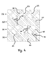
- the Fig. 4 shows a schematic representation of two turbomolecular pumping stages. Axially adjacent, a rotor region 26, a stator region 28, a further rotor region 26 and a further stator region 28 are arranged. In each case a rotor region 26 and an adjacent, axially below arranged stator region 28 form a turbomolecular pumping stage. So it's in Fig. 3 two turbomolecular pumping stages shown.
- turbomolecular pump comprises two rotor and two stator disks, which together can also be referred to as turbomolecular pumping stage.
- the pumping direction runs from top to bottom.
- the rotor blades 18 move from left to right.
- the stator blades 20 are arranged statically.
- depressions 22 are arranged inside on a wall 16, not shown (eg Fig. 2 or 3 ) depressions 22 are arranged. Between the recesses 22 webs 24 are arranged. In this embodiment, the webs 24 are made wider than the depressions 22. The depressions 22 as well as the webs 24 are arranged parallel to the stator blades 20. The angle of attack 46 of the stator blades 20 is therefore equal to the pitch 48 of the depressions 22 at their radially outer ends. The depressions 22 are also located centrally in the circumferential direction between the stator blades 20. The recesses 22 thus extend in the pumping direction from an upper intake side to a lower discharge side continuously over both illustrated turbomolecular pump stages.
- the angle of attack 50 of the rotor blades 18 is 90 ° greater than the angle of attack 46 of the stator blades 20.
- the rotor blades 18 and the stator blades 20 are therefore aligned at their radially outer ends perpendicular to each other.
- the radially outer ends of the rotor blades 18 are therefore also arranged perpendicular to the slope 48 of the recesses 22.
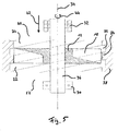
- the Fig. 5 schematically shows some components of a turbomolecular pump according to the invention, in a schematic diagram of a rotor blade designated as a blade rotor 12 with blades 18 which rotatably mounted on a rotor shaft 36 and of which only a rotor disk 12 is shown.
- a blade rotor 12 rotates with the rotor shaft 36 in the rotor rotation direction 44.
- the rotor disk 12 is shown in section.
- the visible rotor blade 18 to the right of the axis of rotation 34 extends axially upward away from the viewer, while the visible rotor blade on the left of the axis of rotation 34 extends axially up to the viewer.
- the rotor shaft 36 and the rotor disk 12 rotate about their axis of rotation 34.
- the rotor shaft 36 is mounted on the discharge side 52 with a rolling bearing 30 radially and preferably also axially.
- the rolling bearing 30 may be embodied for example as a ball bearing or as a cylindrical roller bearing.
- the rotor shaft 36 is mounted with a non-contact and lubrication-free radial bearing 32, preferably with a magnetic bearing.
- the paddle wheel 12 of the Fig. 5 is surrounded by a housing 38.
- the housing 38 has recesses 22 on its inner side facing the blade rotor 12.
- a ring element such as a spacer ring 54 (see. Fig. 1 ) be provided with recesses 22 according to the invention, ie, the component 38 in Fig. 5 then represents such a spacer ring, which cooperates in the manner according to the invention with the rotor disk 12.
- the recesses 22 are arranged helically around the blade rotor 12 in the form of grooves.
- the sense of rotation of the helical depressions 22 corresponds to the rotor rotation direction 44 of the blade rotor 12 Fig. 2 . 3 and 5
- the direction of rotation corresponds to that of a left-handed thread.
- webs 24 are formed between the recesses 22.
- the webs 24 are here designed as wide as the wells 22.
- the pump-active portion of the inner wall of the housing 38 goes into Fig. 5 axially beyond the blade rotor 12 in both directions. In Fig. 5 have the wells 22 a slope which is less than 45 °.
- the depressions 22 are designed as vertically milled grooves.
- a blade stator also referred to as a stator disk
- Axially above and below the blade rotor 12 further turbomolecular pumping stages may be further arranged.
- the structure can therefore, for example, according to the turbomolecular pumping section according to Fig. 1 be elected.
- stator disk 12 adjacent to the rotor disk.
- two or more rotor disks may be arranged axially immediately following one another, before a stator disk follows again, ie at least one pair of immediately successive rotor disks is present, between which no stator disk is arranged in each case.
- stator disks can also be provided exclusively rotor disks, ie on stator discs can be completely dispensed with, at least for a turbomolecular pumping section of the turbomolecular pump.
- a turbomolecular pumping section of a turbomolecular pump for such a structure of one or more turbomolecular pumping sections of a turbomolecular pump and for such a turbomolecular pump as a whole, which otherwise has a typical structure such as in Fig.
- annular or sleeve-shaped elements each having a surrounding the rotor disks wall on at least one pump effective portion of their rotor disks facing side at least one depression is provided, but this is not mandatory.
- a Holweck stator can be arranged around the blade rotor of a turbomolecular pumping stage.
- gas particles that are accelerated outwardly from the rotor against the housing inner wall are deflected by a Holweckstatorgewinde in an axial direction. This in turn becomes the probability of passage increases in the conveying direction and thus improves the power density of a turbomolecular pump.
Landscapes
- Engineering & Computer Science (AREA)
- Mechanical Engineering (AREA)
- General Engineering & Computer Science (AREA)
- Non-Positive Displacement Air Blowers (AREA)
Abstract
Die Erfindung betrifft eine Turbomolekularpumpe mit wenigstens einer Turbomolekularpumpstufe, die zumindest einen um eine Achse (34) drehbar gelagerten Schaufelrotor (12) umfasst, wobei eine den Schaufelrotor (12) zumindest teilweise umgebende Wand (16) auf wenigstens einem pumpwirksamen Teilbereich ihrer dem Schaufelrotor (12) zugewandten Seite mit zumindest einer Vertiefung versehen ist. Ferner betrifft die Erfindung eine Turbomolekularpumpemit wenigstens einer Turbomolekularpumpstufe, die zumindest in einem Teilaxialbereich von einem Holweckstator umgeben ist, dessen pumpwirksame Seite dem Schaufelrotor (12) der Turbomolekularpumpstufe zugewandt ist.The invention relates to a turbomolecular pump having at least one turbomolecular pumping stage which comprises at least one blade rotor (12) rotatably mounted about an axis (34), a wall (16) at least partially surrounding the blade rotor (12) on at least one pumping effective portion of its blade rotor (12). 12) facing side is provided with at least one recess. Furthermore, the invention relates to a turbomolecular pump having at least one turbomolecular pumping stage, which is surrounded by a Holweckstator at least in a Teilaxialbereich whose pump effective side facing the blade rotor (12) of the turbomolecular pumping stage.
Description
Die Erfindung betrifft eine Turbomolekularpumpe mit wenigstens einer Turbomolekularpumpstufe, die zumindest einen um eine Achse drehbar gelagerten Schaufelrotor umfasst.The invention relates to a turbomolecular pump having at least one turbomolecular pump stage, which comprises at least one blade rotor rotatably mounted about an axis.
Derartige Turbomolekularpumpen sind grundsätzlich bekannt und werden z.B. in der Halbleiterindustrie und in der physikalischen Forschung eingesetzt, um ein dort benötigtes Hochvakuum zu erzeugen. Die Turbomolekularpumpe zeichnet sich durch einen nachstehend auch als Rotor bezeichneten Schaufelrotor aus, dessen Aufbau an den Rotor einer Turbine erinnert. Der Schaufelrotor wirkt mit einem im Folgenden auch als Stator bezeichneten Schaufelstator zusammen und rotiert üblicherweise mit einer derart hohen Geschwindigkeit, dass die Tangentialgeschwindigkeit der einzelnen Rotorschaufeln in ähnlicher Größenordnung zu der mittleren thermischen Geschwindigkeit von zu fördernden Teilchen liegt. Bei einer senkrechten Pumprichtung von oben nach unten kollidiert die Mehrzahl der Teilchen mit einer Unterseite einer winklig angestellten Rotorschaufel. Durch eine Vorzugsrichtung der Unterseite der Rotorschaufel in Pumprichtung entsteht eine Pumpwirkung.Such turbomolecular pumps are basically known and are known e.g. used in the semiconductor industry and in physical research to generate a high vacuum needed there. The turbomolecular pump is characterized by a blade rotor, also referred to below as a rotor, whose structure is reminiscent of the rotor of a turbine. The blade rotor interacts with a blade stator, also referred to below as a stator, and usually rotates at such a high speed that the tangential velocity of the individual rotor blades is of a similar magnitude to the mean thermal velocity of particles to be conveyed. In a vertical pumping direction from top to bottom, the majority of the particles collide with a bottom surface of an angularly pitched rotor blade. By a preferred direction of the bottom of the rotor blade in the pumping direction creates a pumping action.
Der Rotor muss außerdem von einer Wand umgeben sein, um einen Rückfluss der Teilchen außerhalb des Rotorbereiches zu verhindern. Eine solche Wand wird z.B. von der Innenseite eines die Turbomolekularpumpstufe enthaltenden Gehäuses oder von den Innenseiten von zwischen einzelnen Statorscheiben angeordneten Statordistanzringen gebildet. Diese Wand weist eine zylindrische Innenfläche auf, die konzentrisch zu dem Rotor angeordnet ist und deren Vorzugsrichtung nach radial innen und somit in Pumprichtung zeigt. Teilchen, die von selbst oder nach Kollision mit einer Rotorschaufel auf die zylindrische Innenfläche der Wand treffen, erfahren dort keine Pumpwirkung mehr.The rotor must also be surrounded by a wall to prevent backflow of the particles outside the rotor area. Such a wall is formed, for example, from the inside of a housing containing the turbomolecular pumping stage or from the insides of stator stator rings arranged between individual stator disks. This wall has a cylindrical inner surface, which is arranged concentrically to the rotor and whose preferred direction points radially inward and thus in the pumping direction. Particles that by themselves or after colliding with a rotor blade on the cylindrical inner surface of the wall meet there no pumping action more.
Vor diesem Hintergrund ist es die Aufgabe der Erfindung, die Leistung von Turbomolekularpumpen zu verbessern.Against this background, it is the object of the invention to improve the performance of turbomolecular pumps.
Diese Aufgabe wird durch eine Turbomolekularpumpe mit den Merkmalen des Anspruchs 1 gelöst, und insbesondere dadurch, dass eine den Schaufelrotor zumindest teilweise umgebende Wand auf wenigstens einem pumpwirksamen Teilbereich ihrer dem Schaufelrotor zugewandten Seite mit zumindest einer Vertiefung versehen ist.This object is achieved by a turbomolecular pump with the features of claim 1, and in particular in that a wall at least partially surrounding the blade rotor is provided on at least one pump effective portion of its blade rotor side facing with at least one recess.
Von Molekularpumpen z.B. nach Gaede oder Holweck ist bekannt, dass eine solche Vertiefung den zu fördernden Teilchen selbst eine weitere Vorzugsrichtung geben kann. Vorteilhaft dafür ist, wenn die Teilchen bereits eine Vorzugsrichtung besitzen, bevor sie in die Vertiefung eintreten, so dass die Mehrheit der Teilchen auf eine mit ihrer Normalen in Pumprichtung zeigende Fläche der Vertiefung trifft. Dies ist bei einem Schaufelrotor einer Turbomolekularpumpe, der gegenüber einer Vertiefung angeordnet ist, im Allgemeinen gegeben, da durch die Rotation der Rotorschaufeln eine tangentiale Geschwindigkeitskomponente der Teilchen im Allgemeinen nicht Null ist, sondern mit einem Betrag größer Null in Drehrichtung zeigt. Dadurch kann die Wand gewissermaßen selbst zu einem pumpaktiven Teilbereich werden.From molecular pumps e.g. According to Gaede or Holweck, it is known that such a depression itself can give the particles to be conveyed a further preferred direction. It is advantageous if the particles already have a preferred direction before they enter the depression, so that the majority of the particles strike an area of the depression pointing with their normal in the pumping direction. This is generally the case with a blade rotor of a turbomolecular pump located opposite a recess, because, due to the rotation of the rotor blades, a tangential velocity component of the particles is generally not zero but with an amount greater than zero in the direction of rotation. As a result, the wall can effectively become a pump-active subarea itself.
Die Leistung der Turbomolekularpumpe kann dadurch verbessert werden, dass Teilchen, die auf die Wand treffen, eine Vorzugsrichtung in Pumprichtung erhalten.The performance of the turbomolecular pump can be improved by giving particles which hit the wall a preferred direction in the pumping direction.
Es ist erfindungsgemäß besonders einfach und kostengrünstig, eine solche Vertiefung in die dem Schaufelrotor zugewandte Seite der Wand einzubringen. Eine solche Vertiefung kann beispielsweise einfach mit einem gewöhnlichen Fräswerkzeug eingebracht werden.It is inventively particularly simple and kostengrünstig to bring such a depression in the blade rotor facing side of the wall. A such depression can be easily introduced, for example, with an ordinary milling tool.
Ferner können dadurch an einem bestehenden Flansch mit einer bestehenden Pumpe das Saugvermögen und die Kompression erhöht werden. Außerdem ermöglicht die Erfindung die technische Anpassung eines statischen Bauteils der Turbomolekularpumpe. Statische Bauteile sind nicht wie Rotorbauteile so hohen mechanischen Belastungen ausgesetzt. Sie können daher ohne Qualifizierung verändert und eingebaut werden. Deshalb sind Weiterentwicklungen von Turbomolekularpumpen entwicklungstechnisch besonders vorteilhaft, wenn sie lediglich - wie hier erfindungsgemäß möglich - statische Bauteile betreffen.Further, this can be increased on an existing flange with an existing pump, the pumping speed and compression. In addition, the invention enables the technical adaptation of a static component of the turbomolecular pump. Static components are not exposed to such high mechanical loads as rotor components. They can therefore be modified and installed without qualification. For this reason, further developments of turbomolecular pumps are particularly advantageous in terms of development if they merely relate to static components, as is possible according to the invention here.
Die Pumpwirkung wird weiter verbessert, wenn die Vertiefung einen Verlauf mit einer axialen Komponente und/oder mit einer von Null verschiedenen Steigung aufweist. Dadurch erhalten die Teilchen eine Vorzugsrichtung mit ebenfalls einer axialen Komponente. Die Pumpwirkung in axialer Richtung wird also verbessert.The pumping action is further improved if the depression has a course with an axial component and / or with a non-zero pitch. As a result, the particles are given a preferential direction, likewise with an axial component. The pumping action in the axial direction is thus improved.
Vorteilhaft kann die Vertiefung einen spiral- oder schraubenförmigen Verlauf aufweisen. Die Vertiefung kann also einen Gewindeverlauf besitzen, der dem Vertiefungsverlauf bei Gaede'schen Gewindepumpen oder Molekularpumpen nach Holweck entspricht. Die Vertiefung kann als Helix ausgebildet sein. Dadurch wird den Teilchen noch gleichmäßiger die gewünschte Vorzugsrichtung beigebracht. Der spiral- oder schraubenförmige Verlauf der Vertiefung besitzt vorteilhaft den gleichen Drehsinn wie der Schaufelrotor.Advantageously, the recess may have a spiral or helical course. The recess may thus have a thread profile corresponding to the recess profile in Gaede'sche screw pumps or molecular pumps according to Holweck. The depression may be formed as a helix. As a result, the particles are taught even more uniformly the desired preferred direction. The spiral or helical course of the depression advantageously has the same direction of rotation as the blade rotor.
Die Vertiefung kann ferner nut- oder kanalartig ausgebildet sein. Die Führung der Teilchen in ihrer Vorzugsrichtung wird dadurch weiter verbessert. Eine derartige Nut oder ein derartiger Kanal lässt sich besonders einfach in eine Wandinnenseite einbringen.The recess may also be formed groove or channel-like. The guidance of the particles in their preferred direction is thereby further improved. Such a groove or channel can be particularly easily introduced into a wall inside.
Vorteilhaft ist ferner der pumpwirksame Teilbereich mit einer Mehrzahl von, insbesondere unzusammenhängenden, Vertiefungen versehen. Dabei können die Vertiefungen vorteilhaft parallel zueinander verlaufen. Durch das Vorsehen mehrerer erfindungsgemäßer Vertiefungen kann die Pumpwirkung der Wandinnenseite insbesondere proportional zur Zahl der Vertiefungen verstärkt werden. Unzusammenhängende und/oder parallele Vertiefungen lassen sich ferner besonders einfach einbringen und verhindern ein Rückströmen zwischen den Vertiefungen.Advantageously, the pump-effective portion is further provided with a plurality of, in particular unrelated, depressions. In this case, the depressions can advantageously extend parallel to one another. By providing a plurality of indentations according to the invention, the pumping action of the inside of the wall can be increased, in particular proportionally to the number of recesses. Disconnected and / or parallel wells are also particularly easy to introduce and prevent backflow between the wells.
Vorteilhaft ist der pumpwirksame Teilbereich der Wand als Holweckstator ausgebildet. So kann mit wenigen konstruktiven Maßnahmen der für sich bekannte Holweckstator auf eine Turbomolekularpumpstufe angewendet werden.Advantageously, the pump-effective portion of the wall is designed as Holweckstator. So can be applied to a Turbomolekularpumpstufe with a few design measures of the known Holweckstator.
Die Wand kann vorteilhaft von einem den Schaufelrotor umgebenden Gehäuse gebildet sein. Der pumpwirksame Teilbereich ist dabei auf der Innenseite des Gehäuses ausgebildet. Dadurch braucht nicht eine zusätzliche Wand in das Pumpengehäuse eingebracht zu werden. Die Vertiefung lässt sich außerdem beim Gehäuseguss oder durch Einfräsung herstellen. Insbesondere kann das Gehäuse das Außengehäuse der Pumpe darstellen. Dadurch werden noch weniger Einzelteile benötigt.The wall may advantageously be formed by a housing surrounding the blade rotor. The pump-effective portion is formed on the inside of the housing. This does not require an additional wall to be introduced into the pump housing. The recess can also be produced by casting casings or by milling. In particular, the housing may be the outer housing of the pump. As a result, even fewer items are needed.
Die Wand kann aber z.B. auch von einem den Schaufelrotor umgebenden Ringelement gebildet und der pumpwirksame Teilbereich auf der Innenseite des Ringelements ausgebildet sein. Das Ringelement ist einfach zu bearbeiten und zu montieren, stellt jedoch ein zusätzliches Teil der Vakuumpumpe dar. Das Ringelement kann dazu ausgebildet sein, zwischen zwei Statorscheiben angeordnet zu sein und so deren axialen Abstand zwischen einander festzulegen. Das Ringelement kann insbesondere ein Distanzring, ein Abstandsring, eine Distanzhülse und/oder eine Abstandshülse sein.However, the wall may also be formed, for example, by a ring element surrounding the blade rotor and the pump-effective partial region may be formed on the inside of the ring element. The ring element is easy to machine and assemble, but constitutes an additional part of the vacuum pump. The ring element may be designed to be arranged between two stator disks and thus fix their axial distance between each other. The ring element may in particular be a spacer ring, a spacer ring, a spacer sleeve and / or a spacer sleeve.
Es kann also erfindungsgemäß vorgesehen sein, ohnehin vorhandene Elemente wie Ring- oder Hülsenelemente zwischen aufeinander folgenden Statorscheiben dazu zu nutzen, pumpwirksame Teilbereiche zu bilden, die auf ihrer dem Schaufelrotor zugewandten Seite mit zumindest einer Vertiefung versehen sind.It may therefore be provided according to the invention to use existing elements such as ring or sleeve elements between successive stator disks to form pump-effective subregions, which are provided on their side facing the blade rotor with at least one recess.
In einer vorteilhaften Ausführungsform umfasst der Schaufelrotor eine Mehrzahl von axial aufeinanderfolgend angeordneten, einstückig miteinander verbundenen oder separaten Rotorscheiben. Die Pumpleistung der Turbomolekularpumpe kann durch mehrere Rotorscheiben weiter verbessert werden.In an advantageous embodiment, the blade rotor comprises a plurality of axially successively arranged, integrally connected or separate rotor disks. The pumping power of the turbomolecular pump can be further improved by a plurality of rotor disks.
Vorteilhaft kann vorgesehen sein, dass der pumpwirksame Teilbereich sich in axialer Richtung lediglich über eine, bevorzugt die der Ansaugseite der Pumpe am nächsten gelegene Rotorscheibe umfassende, Teilmenge von Rotorscheiben erstreckt, insbesondere über genau eine Rotorscheibe. An der in Pumprichtung ersten Rotorscheibe kann die Pumpwirkung durch die erfindungsgemäße Vertiefung besonders wirksam verbessert werden.Advantageously, it can be provided that the pump-effective portion extends in the axial direction only over a, preferably the suction side of the pump nearest rotor disk comprehensive, subset of rotor disks, in particular over exactly one rotor disk. At the first rotor disk in the pumping direction, the pumping effect can be improved particularly effectively by the recess according to the invention.
Es können zumindest einige Schaufeln eines mit dem Schaufelrotor zusammenwirkenden Schaufelstators mit der Wand verbunden sein. Daraus ergibt sich ein einfacherer Aufbau der Turbomolekularpumpe.At least some blades of a blade stator cooperating with the blade rotor may be connected to the wall. This results in a simpler construction of the turbomolecular pump.
Der pumpwirksame Teilbereich kann sich vorteilhaft axial außerhalb von Schaufeln eines mit dem Schaufelrotor zusammenwirkenden Schaufelstators befinden. Der pumpwirksame Teilbereich ist dann nur gegenüber den Schaufeln des Schaufelrotors, also nicht auf der Höhe des Stators, angeordnet.The pump-effective portion can advantageously be located axially outside of blades of a blade stator interacting with the blade rotor. The pump-effective portion is then arranged only with respect to the blades of the blade rotor, that is not at the height of the stator.
Alternativ kann sich ein pumpwirksamer Bereich der Wand zumindest im Wesentlichen über die gesamte axiale Länge der Turbomolekularpumpe erstrecken. Vorteilhaft kann weiter vorgesehen sein, dass ein mit dem Schaufelrotor zusammenwirkender Schaufelstator eine Mehrzahl axial aufeinander folgend angeordneter Statorscheiben umfasst, wobei der pumpwirksame Teilbereich sich lediglich axial zwischen den Statorscheiben und/oder axial benachbart zu wenigstens einer der Statorscheiben befindet. Beispielsweise kann der pumpwirksame Teilbereich von den Innenseiten von jeweils zwischen Statorscheiben und somit auf der Höhe einer Rotorscheibe gelegenen Statordistanzringen gebildet sein. Dies erleichtert die Einbringung der Vertiefung.Alternatively, a pump-effective region of the wall may extend at least substantially over the entire axial length of the turbomolecular pump. Advantageously, it can further be provided that a blade stator interacting with the blade rotor comprises a plurality of stator disks arranged axially one after the other, wherein the pump-effective portion is only axially between the stator disks and / or axially adjacent to at least one of the stator disks. For example, the pump-effective portion may be formed by the inner sides of each of stator disks and thus located at the height of a rotor disk stator spacer rings. This facilitates the insertion of the recess.
Vorteilhaft kann ferner vorgesehen sein, dass Schaufeln eines mit dem Schaufelrotor zusammenwirkenden Schaufelstators in einem radial äußeren Endbereich jeweils einen Anstellwinkel aufweisen, der zumindest näherungsweise gleich einer Steigung der Vertiefung ist. Die Vertiefung erstreckt sich dabei zumindest im Wesentlichen parallel zur Ausrichtung bzw. zu dem Anstellwinkel der Statorschaufeln. Dadurch wird die Weiterleitung der Teilchen weiter verbessert.Advantageously, it may further be provided that blades of a blade stator interacting with the blade rotor have in each case an angle of attack in a radially outer end region which is at least approximately equal to a pitch of the recess. The recess extends at least substantially parallel to the orientation or to the angle of attack of the stator blades. This further improves the transmission of the particles.
In einer weiteren Ausführungsform weisen die Schaufeln des Schaufelrotors in einem radial äußeren Endbereich jeweils einen Anstellwinkel auf, der zwischen 45° und 90° von einer Steigung der Vertiefung verschieden ist. Die Vertiefung ist hierbei senkrecht oder in einem spitzen Winkel zu den Rotorschaufeln angeordnet.In a further embodiment, the blades of the blade rotor in each case have an angle of attack in a radially outer end region which is different between a pitch of 45 ° and 90 ° of a pitch of the recess. The recess is arranged perpendicular or at an acute angle to the rotor blades.
Es kann vorteilhaft auch vorgesehen sein, dass der pumpwirksame Teilbereich eine Mehrzahl parallel verlaufender Vertiefungen aufweist, die durch Stege voneinander getrennt sind, wobei die Anzahl der Stege zumindest näherungsweise gleich der Anzahl von Schaufeln pro Statorscheibe eines mit dem Schaufelrotor zusammenwirkenden Schaufelstators ist. Es kann vorteilhaft sein, genauso viele Vertiefungen bzw. genauso viele Stege wie Statorschaufeln vorzusehen. Ferner kann auch die Anzahl der Rotorschaufeln gleich der Anzahl der Statorschaufeln sein. Dadurch kann die Durchtrittswahrscheinlichkeit der einzelnen Teilchen weiter verbessert werden.It may also be advantageously provided that the pump-effective portion has a plurality of parallel depressions, which are separated by webs, wherein the number of webs is at least approximately equal to the number of blades per stator of a cooperating with the blade rotor paddle stator. It may be advantageous to provide just as many depressions or as many webs as stator blades. Furthermore, the number of rotor blades can be equal to the number of stator blades. As a result, the passage probability of the individual particles can be further improved.
Die Statorschaufeln können mit den Stegen der Wandinnenseite fest verbunden, insbesondere materialschlüssig ausgeführt, sein. Die Statorschaufeln können also den Stegen zwischen den Vertiefungen entspringen. Die Vertiefungen können sich außerdem zwischen den Statorschaufeln hindurch erstrecken. Die Vertiefungen können sich auch kontinuierlich über mehrere Turbomolekularpumpstufen oder über mehrere abwechselnd angeordnete Rotor- und Statorscheiben hinweg erstrecken. Die Vertiefungen können als mehrgängiges Innengewinde ausgeführt sein. So lässt sich eine verbesserte kontinuierliche Teilchenströmung in dem pumpwirksamen Teilbereich erreichen.The stator blades can be fixedly connected to the webs of the inside of the wall, in particular designed to be material-locking. The stator blades can thus spring from the webs between the recesses. The recesses may also extend between the stator vanes. The recesses may also extend continuously over a plurality of turbomolecular pumping stages or over a plurality of alternately arranged rotor and stator disks. The depressions can be designed as multi-threaded internal thread. Thus, an improved continuous particle flow in the pump effective portion can be achieved.
Eine erfindungsgemäße Vertiefung kann ferner auch auf der Innenseite eines Statordistanzrings angeordnet sein. Dies erleichtert die Fertigung besonders von Turbomolekularpumpen mit mehreren Turbomolekularpumpstufen oder mit mehreren abwechselnd angeordneten Rotor- und Statorscheiben.A recess according to the invention can also be arranged on the inside of a stator spacer ring. This facilitates the production of turbomolecular pumps in particular with several turbomolecular pumping stages or with a plurality of alternately arranged rotor and stator disks.
Die Aufgabe der Erfindung löst ferner eine Turbomolekularpumpe mit wenigstens einer Turbomolekularpumpstufe, die zumindest in einem Teilaxialbereich von einem Holweckstator umgeben ist, dessen pumpwirksame Seite dem Schaufelrotor der Turbomolekularpumpstufe zugewandt ist.The object of the invention also solves a turbomolecular pump having at least one turbomolecular pumping stage, which is surrounded at least in a Teilaxialbereich by a Holweckstator whose pump-effective side facing the blade rotor of the turbomolecular pumping stage.
Die Erfindung kombiniert hierdurch eine Turbomolekularpumpstufe mit einer Holweckpumpstufe bzw. schafft eine Hybridpumpstufe aus diesen beiden Pumpentypen.The invention thereby combines a turbomolecular pump stage with a Holweck pump stage or creates a hybrid pump stage from these two pump types.
Mögliche konkrete Ausgestaltungen auch dieser Pumpe sind vorstehend und in den abhängigen Ansprüchen angegeben.Possible specific embodiments of this pump are given above and in the dependent claims.
Weitere Ausführungsformen der Erfindung sind in den abhängigen Ansprüchen, der Beschreibung sowie den Zeichnungen angegeben.Further embodiments of the invention are indicated in the dependent claims, the description and the drawings.
Die Erfindung wird nachfolgend lediglich beispielhaft unter Bezugnahme auf die Zeichnungen erläutert.
- Fig. 1
- zeigt eine Schnittansicht einer erfindungsgemäßen Turbomolekularpumpe.
- Fig. 2
- zeigt in Perspektivansicht eine erfindungsgemäße Pumpstufe einer Turbomolekularpumpe.
- Fig. 3
- zeigt in einer anderen Perspektivansicht einen Teil der Pumpstufe von
Fig. 2 . - Fig. 4
- zeigt eine Prinzipdarstellung einer erfindungsgemäßen Vertiefungsanordnung.
- Fig. 5
- zeigt in einer Prinzipdarstellung den Schaufelrotor einer erfindungsgemäßen Turbomolekularpumpstufe im Querschnitt längs der Drehachse des Rotors.
- Fig. 1
- shows a sectional view of a turbomolecular pump according to the invention.
- Fig. 2
- shows in perspective view a pumping stage of a turbomolecular pump according to the invention.
- Fig. 3
- shows in another perspective view a part of the pumping stage of
Fig. 2 , - Fig. 4
- shows a schematic diagram of a recess arrangement according to the invention.
- Fig. 5
- shows in a schematic representation of the blade rotor of a turbomolecular pumping stage according to the invention in cross section along the axis of rotation of the rotor.
Die
Der Schaufelstator 14 der
Die Wand 16 umschließt den Schaufelrotor 12 in radialer Richtung. Auf der Innenseite, also auf der dem Schaufelrotor zugewandten Seite, weist die Wand 16 Vertiefungen 22 auf. Die Vertiefungen 22 sind jeweils als Nut ausgeführt und erstrecken sich schraubenförmig in axialer Richtung. Zwischen den Vertiefungen 22 sind Stege 24 ausgebildet. Zwischen den Stegen 24 besteht also eine Art Kanal in einem pumpwirksamen Teilbereich. Die Anzahl der Vertiefungen 22 und die Anzahl der Stege 24 sind jeweils gleich der Anzahl der Statorschaufeln 20 und gleich der Anzahl der Rotorschaufeln 18. Die Vertiefungen 22 sind parallel zueinander und parallel zu den äußeren Enden der Statorschaufeln 20 angeordnet. Die Pumprichtung richtet sich in
Die Stege 24 zwischen den Vertiefungen 22 verlaufen parallel zu den Vertiefungen 22. Dabei sind sie schmaler als die Vertiefungen 22 ausgeführt. Die Vertiefungen 22 sind als kanalartige, rechtwinklige Nuten auf der Innenseite der Wand 16 ausgeführt. Entsprechend sind die Stege 24 ebenfalls rechtwinklig ausgebildet. Die Stege 24 und die Vertiefungen 22 erstrecken sich parallel zu den radial äußeren Enden der Statorschaufeln 20. Die Stege 24 sind dabei jeweils in Umfangsrichtung an der gleichen Stelle wie die Statorschaufeln 20 angeordnet. Die axial unteren, also in der
Die
Anstatt von "Stufen" kann auch von "Scheiben" gesprochen werden, d.h. diese exemplarisch dargestellte Turbomolekularpumpe umfasst zwei Rotor- und zwei Statorscheiben, die gemeinsam auch als Turbomolekularpumpstufe bezeichnet werden können.Instead of "stages", it is also possible to speak of "slices", i. This exemplified turbomolecular pump comprises two rotor and two stator disks, which together can also be referred to as turbomolecular pumping stage.
Die Pumprichtung verläuft von oben nach unten. In den Rotorbereichen 26 bewegen sich die Rotorschaufeln 18 von links nach rechts. In den Statorbereichen sind die Statorschaufeln 20 statisch angeordnet.The pumping direction runs from top to bottom. In the rotor regions 26, the
Innen an einer nicht dargestellten Wand 16 (z.B. nach
Der Anstellwinkel 50 der Rotorschaufeln 18 ist um 90° größer als der Anstellwinkel 46 der Statorschaufeln 20. Die Rotorschaufeln 18 und die Statorschaufeln 20 sind also an ihren radial äußeren Enden senkrecht zueinander ausgerichtet. Die radial äußeren Enden der Rotorschaufeln 18 sind daher auch senkrecht zur Steigung 48 der Vertiefungen 22 angeordnet.The angle of
Die
In
Der Schaufelrotor 12 der
Die Vertiefungen 22 sind in Form von Nuten schraubenförmig um den Schaufelrotor 12 herum angeordnet. Der Drehsinn der schraubenförmigen Vertiefungen 22 entspricht der Rotordrehrichtung 44 des Schaufelrotors 12. In den
Axial unterhalb und/oder oberhalb des Schaufelrotors 12 kann ein auch als Statorscheibe bezeichneter Schaufelstator benachbart angeordnet sein. Axial oberhalb und unterhalb des Schaufelrotors 12 können ferner weitere Turbomolekularpumpstufen angeordnet sein. Der Aufbau kann also z.B. entsprechend dem Turbomolekular-Pumpabschnitt gemäß
Es ist alternativ auch möglich, keine zur Rotorscheibe 12 benachbarte Statorscheibe vorzusehen. Beispielsweise können zwei oder mehr Rotorscheiben axial unmittelbar aufeinander folgend angeordnet sein, bevor wieder eine Statorscheibe folgt, d.h. es sind dann wenigstens ein Paar von unmittelbar aufeinander folgenden Rotorscheiben vorhanden, zwischen denen jeweils keine Statorscheibe angeordnet ist. Es können auch ausschließlich Rotorscheiben vorgesehen sein, d.h. auf Statorscheiben kann auch ganz verzichtet werden, zumindest für einen Turbomolekular-Pumpabschnitt der Turbomolekularpumpe. Für einen derartigen Aufbau eines oder mehrerer Turbomolekular-Pumpabschnitte einer Turbomolekularpumpe und für eine derartige Turbomolekularpumpe insgesamt, die ansonsten einen typischen Aufbau wie z.B. in
Wie sich aus den Ausführungsbeispielen ergibt, kann also gemäß der Erfindung ein Holweckstator um den Schaufelrotor einer Turbomolekularpumpstufe herum angeordnet sein. Dadurch werden Gasteilchen, die vom Rotor nach außen gegen die Gehäuseinnenwand beschleunigt werden, durch ein Holweckstatorgewinde in eine axiale Richtung umgelenkt. Dadurch wird wiederum die Durchtrittswahrscheinlichkeit in Förderrichtung erhöht und somit die Leistungsdichte einer Turbomolekularpumpe verbessert.As can be seen from the exemplary embodiments, according to the invention, a Holweck stator can be arranged around the blade rotor of a turbomolecular pumping stage. As a result, gas particles that are accelerated outwardly from the rotor against the housing inner wall are deflected by a Holweckstatorgewinde in an axial direction. This in turn becomes the probability of passage increases in the conveying direction and thus improves the power density of a turbomolecular pump.
Bei aus dem Stand der Technik bekannten Anordnungen stießen die zu fördernden Teilchen in dem Radialspalt zwischen dem radial äußeren Ende der Rotorschaufeln und der Gehäuseinnenwand bzw. der Statordistanzringinnenseite gegen eine glatte Fläche. Dort blieben die Teilchen kurz haften und verließen diese Oberfläche wieder mit einer Kosinusverteilung, wobei sie keine weitere Vorzugsrichtung erfuhren. Durch die Erfindung und insbesondere das erfindungsgemäße Holweckgewinde können nun mehr Teilchen die Gehäuseinnenwand bzw. die dem Schaufelrotor zugewandte Innenseite einer Wand mit einer axialen Komponente verlassen, die in Richtung Pumpenauslass, also in Pumprichtung zeigt. Simulationsergebnisse für eine einstufige Turbomolekularpumpe mit zu förderndem Stickstoff haben folgendes ergeben: Ausgegangen wurde von einer Gehäuseinnenwand ohne Vertiefungen, einem Kompressionsverhältnis von K0 = 8,1 und einem Saugvermögen S0 = 2262 L/s. Mit Holweckgewinde verbesserte sich das Kompressionsverhältnis auf K0 = 8,8 und das Saugvermögen auf So = 2304 L/s.In known from the prior art arrangements, the particles to be conveyed in the radial gap between the radially outer end of the rotor blades and the housing inner wall and the stator spacer ring inside against a smooth surface. There, the particles remained briefly adhere and left this surface again with a cosine distribution, where they learned no other preferred direction. By means of the invention and in particular the Holweck thread according to the invention, it is now possible for more particles to leave the housing inner wall or the inner side of a wall facing the blade rotor with an axial component pointing in the pump outlet direction, ie in the pumping direction. Simulation results for a single-stage turbomolecular pump with nitrogen to be delivered have shown the following: The starting point was a housing inner wall without depressions, a compression ratio of K 0 = 8.1 and a pumping speed S 0 = 2262 L / s. Holweck threading improved the compression ratio to K 0 = 8.8 and the suction to So = 2304 L / s.
- 1212
- Schaufelrotor, RotorscheibeBlade rotor, rotor disk
- 1414
- Schaufelstator, StatorscheibePaddle stator, stator disc
- 1616
- Wandwall
- 1818
- Schaufelshovel
- 2020
- Schaufelshovel
- 2222
- Vertiefungdeepening
- 2424
- Stegweb
- 2626
- Rotorbereichrotor area
- 2828
- Statorbereichstator
- 3030
- Wälzlagerroller bearing
- 3232
- Radiallager (Permanentmagnetlager)Radial bearing (permanent magnet bearing)
- 3434
- Rotationsachseaxis of rotation
- 3636
- Rotorwellerotor shaft
- 3838
- Gehäusecasing
- 4040
- Ansaugseitesuction
- 4242
- Pumprichtungpumping direction
- 4444
- RotordrehrichtungRotor rotation
- 4646
- Anstellwinkel der StatorschaufelnIncident angle of the stator blades
- 4848
- Steigung der VertiefungSlope of the depression
- 5050
- Anstellwinkel der RotorschaufelnAngle of attack of the rotor blades
- 5252
- Ausstoßseitedischarge side
- 5454
- Distanzringspacer
- 5656
- Turbomolekular-PumpabschnittTurbo-molecular pump section
- 5858
- Holweck-PumpabschnittHolweck pumping section
Claims (15)
wenigstens einer Turbomolekularpumpstufe, die zumindest einen um eine Achse (34) drehbar gelagerten Schaufelrotor (12) umfasst,
wobei eine den Schaufelrotor (12) zumindest teilweise umgebende Wand (16) auf wenigstens einem pumpwirksamen Teilbereich ihrer dem Schaufelrotor (12) zugewandten Seite mit zumindest einer Vertiefung (22) versehen ist.Turbomolecular pump with
at least one turbomolecular pump stage comprising at least one blade rotor (12) rotatably mounted about an axis (34),
wherein a wall (16) at least partially surrounding the blade rotor (12) is provided with at least one recess (22) on at least one pump-effective partial area of its side facing the blade rotor (12).
dadurch gekennzeichnet, dass
die Vertiefung (22) einen Verlauf mit einer axialen Komponente und/oder mit einer von Null verschiedenen Steigung aufweist.Turbomolecular pump according to claim 1,
characterized in that
the recess (22) has a profile with an axial component and / or with a non-zero pitch.
dadurch gekennzeichnet, dass
die Vertiefung (22) einen spiral- oder schraubenförmigen Verlauf aufweist.Turbomolecular pump according to claim 1 or 2,
characterized in that
the recess (22) has a spiral or helical course.
dadurch gekennzeichnet, dass
die Vertiefung (22) nut- oder kanalartig ausgebildet ist.Turbomolecular pump according to one of the preceding claims,
characterized in that
the recess (22) is groove-shaped or channel-shaped.
dadurch gekennzeichnet, dass
der pumpwirksame Teilbereich mit einer Mehrzahl von, insbesondere unzusammenhängenden, Vertiefungen (22) versehen ist, wobei insbesondere die Vertiefungen (22) parallel zueinander verlaufen.Turbomolecular pump according to one of the preceding claims,
characterized in that
the pump-effective portion is provided with a plurality of, in particular unrelated, recesses (22), wherein in particular the recesses (22) extend parallel to each other.
dadurch gekennzeichnet, dass
der pumpwirksame Teilbereich als Holweckstator ausgebildet ist.Turbomolecular pump according to one of the preceding claims,
characterized in that
the pump-effective portion is formed as Holweckstator.
dadurch gekennzeichnet, dass
die Wand (16) von einem den Schaufelrotor (12) umgebenden Gehäuse (38) gebildet und der pumpwirksame Teilbereich auf der Innenseite des Gehäuses (38) ausgebildet ist, wobei insbesondere das Gehäuse (38) das Außengehäuse der Pumpe ist.Turbomolecular pump according to one of the preceding claims,
characterized in that
the wall (16) is formed by a housing (38) surrounding the blade rotor (12) and the pump-effective portion is formed on the inside of the housing (38), wherein in particular the housing (38) is the outer housing of the pump.
dadurch gekennzeichnet, dass
die Wand (16) von wenigstens einem den Schaufelrotor (12) umgebenden, insbesondere als separater Einsatz ausgebildeten, Ringelement gebildet und der pumpwirksame Teilbereich auf der Innenseite des Ringelements ausgebildet ist, wobei insbesondere das Ringelement ein Distanzring (54), ein Abstandsring, eine Distanzhülse und/oder eine Abstandshülse ist, die zwischen zwei in axialer Richtung aufeinanderfolgenden Statorscheiben (14) angeordnet ist.Turbomolecular pump according to one of the preceding claims,
characterized in that
the wall (16) of at least one the blade rotor (12) formed, in particular designed as a separate insert, ring member and the pump effective portion is formed on the inside of the ring member, wherein in particular the ring member is a spacer ring (54), a spacer ring, a spacer sleeve and / or a spacer sleeve which is arranged between two axially successive stator disks (14).
dadurch gekennzeichnet, dass
der Schaufelrotor (12) eine Mehrzahl von axial aufeinanderfolgend angeordneten, einstückig miteinander verbundenen oder separaten Rotorscheiben umfasst, und/oder dass
der pumpwirksame Teilbereich sich in axialer Richtung lediglich über eine, bevorzugt die der Ansaugseite (40) der Pumpe am nächsten gelegene Rotorscheibe umfassende, Teilmenge von Rotorscheiben erstreckt, insbesondere über genau eine Rotorscheibe.Turbomolecular pump according to one of the preceding claims,
characterized in that
the blade rotor (12) comprises a plurality of axially successively arranged, integrally connected or separate rotor disks, and / or
the pump-effective portion extends in the axial direction only over a, preferably the suction side (40) of the pump closest rotor disk comprehensive, subset of rotor disks, in particular over exactly one rotor disk.
dadurch gekennzeichnet, dass
zumindest einige Schaufeln (20) eines mit dem Schaufelrotor (12) zusammenwirkenden Schaufelstators (14) mit der Wand (16) verbunden sind, und/oder dass
sich der pumpwirksame Teilbereich axial außerhalb von Schaufeln (20) eines mit dem Schaufelrotor (12) zusammenwirkenden Schaufelstators (14) befindet.Turbomolecular pump according to one of the preceding claims,
characterized in that
at least some blades (20) of a blade stator (14) cooperating with the blade rotor (12) are connected to the wall (16), and / or
the pump-effective portion is located axially outside of blades (20) of a blade stator (14) cooperating with the blade rotor (12).
dadurch gekennzeichnet, dass
ein mit dem Schaufelrotor (12) zusammenwirkender Schaufelstator (14) eine Mehrzahl axial aufeinanderfolgend angeordneter Statorscheiben (14) umfasst, wobei der pumpwirksame Teilbereich sich lediglich axial zwischen den Statorscheiben (14) und/oder axial benachbart zu wenigstens einer der Statorscheiben (14) befindet.Turbomolecular pump according to one of the preceding claims,
characterized in that
a vane stator (14) cooperating with the vane rotor (12) comprises a plurality of stator disks (14) arranged axially successively, wherein the pump effective portion is only axially between the stator disks (14) and / or axially adjacent to at least one of the stator disks (14) ,
dadurch gekennzeichnet, dass
Schaufeln (20) eines mit dem Schaufelrotor (12) zusammenwirkenden Schaufelstators (14) in einem radial äußeren Endbereich jeweils einen Anstellwinkel (46) aufweisen, der zumindest näherungsweise gleich einer Steigung (48) der Vertiefung (22) ist.Turbomolecular pump according to one of the preceding claims,
characterized in that
Blades (20) of a blade stator (14) interacting with the blade rotor (12) each have an angle of incidence (46) in a radially outer end region which is at least approximately equal to a pitch (48) of the recess (22).
dadurch gekennzeichnet, dass
Schaufeln (18) des Schaufelrotors (12) in einem radial äußeren Endbereich jeweils einen Anstellwinkel (48) aufweisen, der zwischen 45° und 90° von einer Steigung (48) der Vertiefung (22) verschieden ist.Turbomolecular pump according to one of the preceding claims,
characterized in that
Blades (18) of the blade rotor (12) in each case have a setting angle (48) in a radially outer end region which is different between 45 ° and 90 ° from a pitch (48) of the recess (22).
dadurch gekennzeichnet, dass
der pumpwirksame Teilbereich eine Mehrzahl parallel verlaufender Vertiefungen (22) aufweist, die durch Stege (24) voneinander getrennt sind, wobei die Anzahl der Stege (24) zumindest näherungsweise gleich der Anzahl von Schaufeln (20) pro Statorscheibe (14) eines mit dem Schaufelrotor zusammenwirkenden Schaufelstators (14) ist.Turbomolecular pump according to one of the preceding claims,
characterized in that
the pump-effective portion having a plurality of parallel recesses (22) which are separated by webs (24), wherein the number of webs (24) at least approximately equal to the number of blades (20) per stator disc (14) one with the blade rotor cooperating Schaufelstators (14).
wenigstens einer Turbomolekularpumpstufe, die zumindest in einem Teilaxialbereich von einem Holweckstator umgeben ist, dessen pumpwirksame Seite dem Schaufelrotor (12) der Turbomolekularpumpstufe zugewandt ist.Turbomolecular pump with
at least one turbomolecular pump stage, which is surrounded at least in a Teilaxialbereich by a Holweckstator whose pump effective side facing the blade rotor (12) of the turbomolecular pumping stage.
Applications Claiming Priority (1)
| Application Number | Priority Date | Filing Date | Title |
|---|---|---|---|
| DE102014118083.6A DE102014118083A1 (en) | 2014-12-08 | 2014-12-08 | TURBO MOLECULAR PUMP |
Publications (3)
| Publication Number | Publication Date |
|---|---|
| EP3032107A2 true EP3032107A2 (en) | 2016-06-15 |
| EP3032107A3 EP3032107A3 (en) | 2016-08-31 |
| EP3032107B1 EP3032107B1 (en) | 2020-04-15 |
Family
ID=53673823
Family Applications (1)
| Application Number | Title | Priority Date | Filing Date |
|---|---|---|---|
| EP15191438.9A Active EP3032107B1 (en) | 2014-12-08 | 2015-10-26 | Turbomolecular pump |
Country Status (2)
| Country | Link |
|---|---|
| EP (1) | EP3032107B1 (en) |
| DE (1) | DE102014118083A1 (en) |
Cited By (2)
| Publication number | Priority date | Publication date | Assignee | Title |
|---|---|---|---|---|
| GB2579028A (en) * | 2018-11-14 | 2020-06-10 | Edwards Ltd | Molecular drag stage |
| CN114352553A (en) * | 2021-12-31 | 2022-04-15 | 北京中科科仪股份有限公司 | Vortex mechanism and composite molecular pump |
Family Cites Families (5)
| Publication number | Priority date | Publication date | Assignee | Title |
|---|---|---|---|---|
| US5358373A (en) * | 1992-04-29 | 1994-10-25 | Varian Associates, Inc. | High performance turbomolecular vacuum pumps |
| DE29717764U1 (en) * | 1997-10-06 | 1997-11-20 | Leybold Vakuum GmbH, 50968 Köln | Stator for a turbomolecular vacuum pump |
| DE10010371A1 (en) * | 2000-03-02 | 2001-09-06 | Pfeiffer Vacuum Gmbh | Turbomolecular pump |
| DE10111546A1 (en) * | 2000-05-15 | 2002-01-03 | Pfeiffer Vacuum Gmbh | Gas friction pump |
| DE102013213815A1 (en) * | 2013-07-15 | 2015-01-15 | Pfeiffer Vacuum Gmbh | vacuum pump |
-
2014
- 2014-12-08 DE DE102014118083.6A patent/DE102014118083A1/en not_active Withdrawn
-
2015
- 2015-10-26 EP EP15191438.9A patent/EP3032107B1/en active Active
Non-Patent Citations (1)
| Title |
|---|
| None |
Cited By (3)
| Publication number | Priority date | Publication date | Assignee | Title |
|---|---|---|---|---|
| GB2579028A (en) * | 2018-11-14 | 2020-06-10 | Edwards Ltd | Molecular drag stage |
| CN114352553A (en) * | 2021-12-31 | 2022-04-15 | 北京中科科仪股份有限公司 | Vortex mechanism and composite molecular pump |
| CN114352553B (en) * | 2021-12-31 | 2024-01-09 | 北京中科科仪股份有限公司 | Vortex mechanism and compound molecular pump |
Also Published As
| Publication number | Publication date |
|---|---|
| EP3032107B1 (en) | 2020-04-15 |
| DE102014118083A1 (en) | 2016-06-09 |
| EP3032107A3 (en) | 2016-08-31 |
Similar Documents
| Publication | Publication Date | Title |
|---|---|---|
| EP2025945B1 (en) | Flow working machine with ring canal wall fitting | |
| DE69114647T2 (en) | Axial flow blower. | |
| DE1817430A1 (en) | Regenerative compressor | |
| CH674552A5 (en) | ||
| DE2331614A1 (en) | SIDE CHANNEL FAN | |
| EP2933497B1 (en) | Vacuum pump | |
| WO2016110373A1 (en) | Side-channel blower for an internal combustion engine | |
| WO2015007443A1 (en) | Rotor for a thermal turbomachine | |
| EP3032107B1 (en) | Turbomolecular pump | |
| EP3088743B1 (en) | Side-channel vacuum pump stage with a stripper that is slanted on the suction side | |
| EP2994615A1 (en) | Rotor for a thermal turbomachine | |
| EP2863063B1 (en) | Vacuum pump | |
| EP1483507A1 (en) | Method for producing the rotor of a drag vacuum pump and a rotor produced according to this method | |
| DE102015003224A1 (en) | Self-priming pump | |
| DE202011002809U1 (en) | Stator element and high vacuum pump | |
| WO2003031823A1 (en) | Axially discharging friction vacuum pump | |
| EP2886870B1 (en) | Vacuum pump with improved inlet geometry | |
| EP3032106B1 (en) | Vacuum pump | |
| EP3877653B1 (en) | Multi-stage hydraulic machine | |
| EP3133290B1 (en) | Vacuum pump | |
| DE102014100207B4 (en) | STATOR DISC | |
| EP4194700A1 (en) | Vacuum pump with a holweck pump stage with variable holweck geometry | |
| EP2937525A1 (en) | Aircraft engine | |
| EP4375514A1 (en) | Ventilator | |
| EP2677175A1 (en) | Multi-stage radial fan |
Legal Events
| Date | Code | Title | Description |
|---|---|---|---|
| PUAI | Public reference made under article 153(3) epc to a published international application that has entered the european phase |
Free format text: ORIGINAL CODE: 0009012 |
|
| AK | Designated contracting states |
Kind code of ref document: A2 Designated state(s): AL AT BE BG CH CY CZ DE DK EE ES FI FR GB GR HR HU IE IS IT LI LT LU LV MC MK MT NL NO PL PT RO RS SE SI SK SM TR |
|
| AX | Request for extension of the european patent |
Extension state: BA ME |
|
| PUAL | Search report despatched |
Free format text: ORIGINAL CODE: 0009013 |
|
| AK | Designated contracting states |
Kind code of ref document: A3 Designated state(s): AL AT BE BG CH CY CZ DE DK EE ES FI FR GB GR HR HU IE IS IT LI LT LU LV MC MK MT NL NO PL PT RO RS SE SI SK SM TR |
|
| AX | Request for extension of the european patent |
Extension state: BA ME |
|
| RIC1 | Information provided on ipc code assigned before grant |
Ipc: F04D 29/54 20060101ALI20160728BHEP Ipc: F04D 29/32 20060101ALI20160728BHEP Ipc: F04D 29/64 20060101ALI20160728BHEP Ipc: F04D 19/04 20060101AFI20160728BHEP |
|
| STAA | Information on the status of an ep patent application or granted ep patent |
Free format text: STATUS: REQUEST FOR EXAMINATION WAS MADE |
|
| 17P | Request for examination filed |
Effective date: 20170130 |
|
| RBV | Designated contracting states (corrected) |
Designated state(s): AL AT BE BG CH CY CZ DE DK EE ES FI FR GB GR HR HU IE IS IT LI LT LU LV MC MK MT NL NO PL PT RO RS SE SI SK SM TR |
|
| RIC1 | Information provided on ipc code assigned before grant |
Ipc: F04D 29/68 20060101ALI20190924BHEP Ipc: F04D 29/52 20060101ALI20190924BHEP Ipc: F04D 19/04 20060101AFI20190924BHEP |
|
| GRAP | Despatch of communication of intention to grant a patent |
Free format text: ORIGINAL CODE: EPIDOSNIGR1 |
|
| STAA | Information on the status of an ep patent application or granted ep patent |
Free format text: STATUS: GRANT OF PATENT IS INTENDED |
|
| INTG | Intention to grant announced |
Effective date: 20191105 |
|
| GRAS | Grant fee paid |
Free format text: ORIGINAL CODE: EPIDOSNIGR3 |
|
| GRAA | (expected) grant |
Free format text: ORIGINAL CODE: 0009210 |
|
| STAA | Information on the status of an ep patent application or granted ep patent |
Free format text: STATUS: THE PATENT HAS BEEN GRANTED |
|
| AK | Designated contracting states |
Kind code of ref document: B1 Designated state(s): AL AT BE BG CH CY CZ DE DK EE ES FI FR GB GR HR HU IE IS IT LI LT LU LV MC MK MT NL NO PL PT RO RS SE SI SK SM TR |
|
| REG | Reference to a national code |
Ref country code: CH Ref legal event code: EP |
|
| REG | Reference to a national code |
Ref country code: DE Ref legal event code: R096 Ref document number: 502015012269 Country of ref document: DE |
|
| REG | Reference to a national code |
Ref country code: IE Ref legal event code: FG4D Free format text: LANGUAGE OF EP DOCUMENT: GERMAN |
|
| REG | Reference to a national code |
Ref country code: AT Ref legal event code: REF Ref document number: 1257626 Country of ref document: AT Kind code of ref document: T Effective date: 20200515 |
|
| REG | Reference to a national code |
Ref country code: NL Ref legal event code: MP Effective date: 20200415 |
|
| REG | Reference to a national code |
Ref country code: LT Ref legal event code: MG4D |
|
| PG25 | Lapsed in a contracting state [announced via postgrant information from national office to epo] |
Ref country code: NL Free format text: LAPSE BECAUSE OF FAILURE TO SUBMIT A TRANSLATION OF THE DESCRIPTION OR TO PAY THE FEE WITHIN THE PRESCRIBED TIME-LIMIT Effective date: 20200415 Ref country code: SE Free format text: LAPSE BECAUSE OF FAILURE TO SUBMIT A TRANSLATION OF THE DESCRIPTION OR TO PAY THE FEE WITHIN THE PRESCRIBED TIME-LIMIT Effective date: 20200415 Ref country code: GR Free format text: LAPSE BECAUSE OF FAILURE TO SUBMIT A TRANSLATION OF THE DESCRIPTION OR TO PAY THE FEE WITHIN THE PRESCRIBED TIME-LIMIT Effective date: 20200716 Ref country code: FI Free format text: LAPSE BECAUSE OF FAILURE TO SUBMIT A TRANSLATION OF THE DESCRIPTION OR TO PAY THE FEE WITHIN THE PRESCRIBED TIME-LIMIT Effective date: 20200415 Ref country code: IS Free format text: LAPSE BECAUSE OF FAILURE TO SUBMIT A TRANSLATION OF THE DESCRIPTION OR TO PAY THE FEE WITHIN THE PRESCRIBED TIME-LIMIT Effective date: 20200815 Ref country code: PT Free format text: LAPSE BECAUSE OF FAILURE TO SUBMIT A TRANSLATION OF THE DESCRIPTION OR TO PAY THE FEE WITHIN THE PRESCRIBED TIME-LIMIT Effective date: 20200817 Ref country code: NO Free format text: LAPSE BECAUSE OF FAILURE TO SUBMIT A TRANSLATION OF THE DESCRIPTION OR TO PAY THE FEE WITHIN THE PRESCRIBED TIME-LIMIT Effective date: 20200715 Ref country code: LT Free format text: LAPSE BECAUSE OF FAILURE TO SUBMIT A TRANSLATION OF THE DESCRIPTION OR TO PAY THE FEE WITHIN THE PRESCRIBED TIME-LIMIT Effective date: 20200415 |
|
| PG25 | Lapsed in a contracting state [announced via postgrant information from national office to epo] |
Ref country code: LV Free format text: LAPSE BECAUSE OF FAILURE TO SUBMIT A TRANSLATION OF THE DESCRIPTION OR TO PAY THE FEE WITHIN THE PRESCRIBED TIME-LIMIT Effective date: 20200415 Ref country code: RS Free format text: LAPSE BECAUSE OF FAILURE TO SUBMIT A TRANSLATION OF THE DESCRIPTION OR TO PAY THE FEE WITHIN THE PRESCRIBED TIME-LIMIT Effective date: 20200415 Ref country code: BG Free format text: LAPSE BECAUSE OF FAILURE TO SUBMIT A TRANSLATION OF THE DESCRIPTION OR TO PAY THE FEE WITHIN THE PRESCRIBED TIME-LIMIT Effective date: 20200715 Ref country code: HR Free format text: LAPSE BECAUSE OF FAILURE TO SUBMIT A TRANSLATION OF THE DESCRIPTION OR TO PAY THE FEE WITHIN THE PRESCRIBED TIME-LIMIT Effective date: 20200415 |
|
| PG25 | Lapsed in a contracting state [announced via postgrant information from national office to epo] |
Ref country code: AL Free format text: LAPSE BECAUSE OF FAILURE TO SUBMIT A TRANSLATION OF THE DESCRIPTION OR TO PAY THE FEE WITHIN THE PRESCRIBED TIME-LIMIT Effective date: 20200415 |
|
| REG | Reference to a national code |
Ref country code: DE Ref legal event code: R097 Ref document number: 502015012269 Country of ref document: DE |
|
| PG25 | Lapsed in a contracting state [announced via postgrant information from national office to epo] |
Ref country code: RO Free format text: LAPSE BECAUSE OF FAILURE TO SUBMIT A TRANSLATION OF THE DESCRIPTION OR TO PAY THE FEE WITHIN THE PRESCRIBED TIME-LIMIT Effective date: 20200415 Ref country code: EE Free format text: LAPSE BECAUSE OF FAILURE TO SUBMIT A TRANSLATION OF THE DESCRIPTION OR TO PAY THE FEE WITHIN THE PRESCRIBED TIME-LIMIT Effective date: 20200415 Ref country code: DK Free format text: LAPSE BECAUSE OF FAILURE TO SUBMIT A TRANSLATION OF THE DESCRIPTION OR TO PAY THE FEE WITHIN THE PRESCRIBED TIME-LIMIT Effective date: 20200415 Ref country code: SM Free format text: LAPSE BECAUSE OF FAILURE TO SUBMIT A TRANSLATION OF THE DESCRIPTION OR TO PAY THE FEE WITHIN THE PRESCRIBED TIME-LIMIT Effective date: 20200415 Ref country code: ES Free format text: LAPSE BECAUSE OF FAILURE TO SUBMIT A TRANSLATION OF THE DESCRIPTION OR TO PAY THE FEE WITHIN THE PRESCRIBED TIME-LIMIT Effective date: 20200415 |
|
| PLBE | No opposition filed within time limit |
Free format text: ORIGINAL CODE: 0009261 |
|
| STAA | Information on the status of an ep patent application or granted ep patent |
Free format text: STATUS: NO OPPOSITION FILED WITHIN TIME LIMIT |
|
| PG25 | Lapsed in a contracting state [announced via postgrant information from national office to epo] |
Ref country code: PL Free format text: LAPSE BECAUSE OF FAILURE TO SUBMIT A TRANSLATION OF THE DESCRIPTION OR TO PAY THE FEE WITHIN THE PRESCRIBED TIME-LIMIT Effective date: 20200415 Ref country code: SK Free format text: LAPSE BECAUSE OF FAILURE TO SUBMIT A TRANSLATION OF THE DESCRIPTION OR TO PAY THE FEE WITHIN THE PRESCRIBED TIME-LIMIT Effective date: 20200415 |
|
| 26N | No opposition filed |
Effective date: 20210118 |
|
| PG25 | Lapsed in a contracting state [announced via postgrant information from national office to epo] |
Ref country code: SI Free format text: LAPSE BECAUSE OF FAILURE TO SUBMIT A TRANSLATION OF THE DESCRIPTION OR TO PAY THE FEE WITHIN THE PRESCRIBED TIME-LIMIT Effective date: 20200415 |
|
| REG | Reference to a national code |
Ref country code: CH Ref legal event code: PL |
|
| PG25 | Lapsed in a contracting state [announced via postgrant information from national office to epo] |
Ref country code: MC Free format text: LAPSE BECAUSE OF FAILURE TO SUBMIT A TRANSLATION OF THE DESCRIPTION OR TO PAY THE FEE WITHIN THE PRESCRIBED TIME-LIMIT Effective date: 20200415 Ref country code: LU Free format text: LAPSE BECAUSE OF NON-PAYMENT OF DUE FEES Effective date: 20201026 |
|
| REG | Reference to a national code |
Ref country code: BE Ref legal event code: MM Effective date: 20201031 |
|
| PG25 | Lapsed in a contracting state [announced via postgrant information from national office to epo] |
Ref country code: FR Free format text: LAPSE BECAUSE OF NON-PAYMENT OF DUE FEES Effective date: 20201031 |
|
| PG25 | Lapsed in a contracting state [announced via postgrant information from national office to epo] |
Ref country code: LI Free format text: LAPSE BECAUSE OF NON-PAYMENT OF DUE FEES Effective date: 20201031 Ref country code: CH Free format text: LAPSE BECAUSE OF NON-PAYMENT OF DUE FEES Effective date: 20201031 Ref country code: BE Free format text: LAPSE BECAUSE OF NON-PAYMENT OF DUE FEES Effective date: 20201031 |
|
| PG25 | Lapsed in a contracting state [announced via postgrant information from national office to epo] |
Ref country code: IE Free format text: LAPSE BECAUSE OF NON-PAYMENT OF DUE FEES Effective date: 20201026 |
|
| REG | Reference to a national code |
Ref country code: AT Ref legal event code: MM01 Ref document number: 1257626 Country of ref document: AT Kind code of ref document: T Effective date: 20201026 |
|
| PG25 | Lapsed in a contracting state [announced via postgrant information from national office to epo] |
Ref country code: AT Free format text: LAPSE BECAUSE OF NON-PAYMENT OF DUE FEES Effective date: 20201026 |
|
| PG25 | Lapsed in a contracting state [announced via postgrant information from national office to epo] |
Ref country code: TR Free format text: LAPSE BECAUSE OF FAILURE TO SUBMIT A TRANSLATION OF THE DESCRIPTION OR TO PAY THE FEE WITHIN THE PRESCRIBED TIME-LIMIT Effective date: 20200415 Ref country code: MT Free format text: LAPSE BECAUSE OF FAILURE TO SUBMIT A TRANSLATION OF THE DESCRIPTION OR TO PAY THE FEE WITHIN THE PRESCRIBED TIME-LIMIT Effective date: 20200415 Ref country code: CY Free format text: LAPSE BECAUSE OF FAILURE TO SUBMIT A TRANSLATION OF THE DESCRIPTION OR TO PAY THE FEE WITHIN THE PRESCRIBED TIME-LIMIT Effective date: 20200415 |
|
| PG25 | Lapsed in a contracting state [announced via postgrant information from national office to epo] |
Ref country code: MK Free format text: LAPSE BECAUSE OF FAILURE TO SUBMIT A TRANSLATION OF THE DESCRIPTION OR TO PAY THE FEE WITHIN THE PRESCRIBED TIME-LIMIT Effective date: 20200415 |
|
| PGFP | Annual fee paid to national office [announced via postgrant information from national office to epo] |
Ref country code: GB Payment date: 20231020 Year of fee payment: 9 |
|
| PGFP | Annual fee paid to national office [announced via postgrant information from national office to epo] |
Ref country code: IT Payment date: 20231026 Year of fee payment: 9 Ref country code: CZ Payment date: 20231016 Year of fee payment: 9 |
|
| PGFP | Annual fee paid to national office [announced via postgrant information from national office to epo] |
Ref country code: DE Payment date: 20231227 Year of fee payment: 9 |