EP3032003B1 - Sicherheitszaun, der mehrere feststehende paneele auf einem skelettbau umfasst - Google Patents
Sicherheitszaun, der mehrere feststehende paneele auf einem skelettbau umfasst Download PDFInfo
- Publication number
- EP3032003B1 EP3032003B1 EP15196188.5A EP15196188A EP3032003B1 EP 3032003 B1 EP3032003 B1 EP 3032003B1 EP 15196188 A EP15196188 A EP 15196188A EP 3032003 B1 EP3032003 B1 EP 3032003B1
- Authority
- EP
- European Patent Office
- Prior art keywords
- plates
- fence
- phase
- panels
- panel
- Prior art date
- Legal status (The legal status is an assumption and is not a legal conclusion. Google has not performed a legal analysis and makes no representation as to the accuracy of the status listed.)
- Active
Links
Images

Classifications
-
- E—FIXED CONSTRUCTIONS
- E04—BUILDING
- E04H—BUILDINGS OR LIKE STRUCTURES FOR PARTICULAR PURPOSES; SWIMMING OR SPLASH BATHS OR POOLS; MASTS; FENCING; TENTS OR CANOPIES, IN GENERAL
- E04H17/00—Fencing, e.g. fences, enclosures, corrals
- E04H17/14—Fences constructed of rigid elements, e.g. with additional wire fillings or with posts
- E04H17/16—Fences constructed of rigid elements, e.g. with additional wire fillings or with posts using prefabricated panel-like elements, e.g. wired frames
- E04H17/165—Fences constructed of rigid elements, e.g. with additional wire fillings or with posts using prefabricated panel-like elements, e.g. wired frames using panels with rigid filling and frame
-
- G—PHYSICS
- G08—SIGNALLING
- G08B—SIGNALLING OR CALLING SYSTEMS; ORDER TELEGRAPHS; ALARM SYSTEMS
- G08B13/00—Burglar, theft or intruder alarms
- G08B13/02—Mechanical actuation
- G08B13/12—Mechanical actuation by the breaking or disturbance of stretched cords or wires
- G08B13/122—Mechanical actuation by the breaking or disturbance of stretched cords or wires for a perimeter fence
Definitions
- the invention relates to the technical field of protection fences for detecting an intrusion attempt inside a perimeter delimited by the fence. More particularly, it relates to the field of protective fences comprising panels mounted on a frame comprising fixing posts.
- a protection fence firstly comprises a frame which consists of structural elements. These structural elements comprise fixing posts, generally vertical and, where appropriate, generally horizontal crosspieces which connect two adjacent posts. This fence further comprises various fence panels mounted on this frame, by means of fixing means, typically by screwing. The fence panels at least partially delineate an enclosure so as to form a physical barrier to prevent a person from entering the perimeter of the enclosure.
- each panel comprises two parallel plates, which are separated by electrical insulation means.
- These plates can be rigid, semi-rigid or flexible. They can be full or at least partially openwork. Within the meaning of the invention, they may be formed by a lattice, in particular a wire mesh.
- the aforementioned insulation means which are typically formed by a layer of glue, allow the two plates not to be in mutual electrical contact.
- the two constituent plates of a given panel are connected respectively, one to the ground and the other to the phase. Therefore, if one of the plates is pierced or sawed, during an intrusion attempt, at least a temporary short circuit is formed with the tool or with metal chips, which will be detected.
- the security fence described in this document has a relatively large thickness.
- this fence has a complex mechanical structure, particularly in the area of attachment of the panels on the pole. Then, the need for bare areas at the panel overlap area complicates corrosion protection and fence assembly. Finally, the maintenance of this fence can be inconvenient, especially during a mechanical breakage of the fastening means and / or a malfunction in the electrical continuity.
- the security fence according to the invention is advantageous, compared to the teaching of FR 2,937,360 . Indeed, since the adjacent panels do not overlap, the overall thickness of the fence can be reduced compared to the prior art. In this respect, it should be noted that FR 2,937,360 this overall thickness is necessarily increased by the sum of the two thicknesses of the panels.
- the structure of the fixing means used in the enclosure of the invention can be simplified.
- the adjacent panels extend in two parallel main planes, and in particular the two adjacent panels extend in the same plane. This is advantageous as regards the overall compactness of the fence, especially its thickness.
- edges of the two adjacent panels extend on either side of the structural element. This reduces the mechanical interaction between the two panels, which allows for example an intervention on one of these panels, without having to interfere with the attachment of the other of these panels on the frame.
- the main planes of the two adjacent panels pass through the structural element.
- the extra thickness due to the presence of the panels is therefore limited or non-existent.
- all the ground plates are arranged on a first side of the fence, while all the phase plates are arranged on the opposite side of the fence. This makes it possible to limit the risks of electrical malfunction.
- the connecting means comprise a connecting member comprising a first mounting zone, in particular of a removable mounting, on a ground or phase plate belonging to a first panel, as well as a second mounting zone, in particular of removable mounting, on a ground or phase plate belonging to a second panel.
- the connecting member further comprises a transition zone between said mounting zones, this transition zone extending away from the walls facing the structural element.
- the transition zone has a shape adapted to bypass the structural element, in particular a U or L shape. This measure finds its application, particularly in the case where the element of structure is a pole.
- the connecting member is a bar whose transition zone passes through a recess formed in the structural element. This measure finds its application, especially in the case where the structural element is a cross.
- This enclosure in accordance with this other object of the invention may include all or some of the above features, to the extent that they are technically compatible.
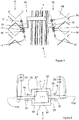
- the figure 1 illustrates a security fence according to the invention.
- this fence is intended to protect a transformer type electrical installation.
- the fence firstly comprises, in a conventional manner, a framework which consists of different structural elements. More precisely, there are posts 1, substantially vertical, which are supported by crossbars 2 substantially horizontal.
- This fence further comprises panels referenced 31 to 39, also of a type known per se. Each panel has two opposing plates extending parallel to each other.
- the figures 3 and 5 illustrate some of these plates, which are respectively referenced 41, 42 and 44, as well as 51, 52 and 54.
- the plates located on one side of the fence are called “mass” , while those on the opposite side are called “live”.
- each plate has a rigid structure, while being perforated.
- these plates are solid, or they are semi-flexible or flexible. They may for example be constituted by a wire mesh.
- ground plates including those 41, 42 and 44, are electrically connected to each other.
- various connecting members 7 and 8 the structure and function of which will be described in more detail in the following. These organs are visible on details II and IV of the figure 1 .
- the ground circuit formed by these plates is connected to a mass not shown, by connection means of a type known per se, which are not represented either.
- phase plates including those 51, 52 and 54, are electrically connected to one another.
- different connecting members 9 and 10 are provided, which are not visible on the figure 1 because they are placed on the opposite, not visible, side of the fence.
- the structure and function of these other organs 9 and 10 will be described in more detail in the following.
- the phase circuit formed by these plates is connected to a phase not shown, by connection means of a type known per se, which are not represented either.
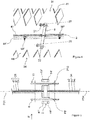
- each linkage member 7, Omega-shaped has a central core 71 extended by two wings 72 and 73, which are terminated by respective tabs 74 and 75.
- each connecting member 9 has a central core 91 extended by two wings 92 and 93, which are terminated by respective tabs 94 and 95.
- the tabs form zones, allowing the removable assembly of the organs on two adjacent panels, while the assembly formed by the core and the two wings defines a transition zone between these mounting areas.
- each plate 41 or 42 is provided with a rod 11 or 12, penetrating into an orifice 74 'or 75' formed in a respective tab 74 or 75.
- Two washers 13 or 14, placed on either side of a nut 15 or 16, are interposed between the facing faces of each plate and each leg.
- solidarity is ensured by an additional nut 17 or 18, in particular of the "indessible" type, provided on the opposite face of each leg.
- Each connecting member 8 or 10 has the shape of an elongate bar, the two ends of which are pierced with orifices. These bars extend through passages P8 and P10, which are formed by indentations formed successively in the different flanges and crossbar 2. The skilled person will spacing the walls opposite the connecting bars, compared to those rims and the crossbar, at a sufficient distance to avoid any risk of inadvertent contact may cause a short circuit.
- each plate 41 or 44 is provided with a rod 21 or 22, penetrating into a respective orifice of the bar 8.
- a rod 21 or 22 penetrating into a respective orifice of the bar 8.
- two washers placed on either side of a nut are interposed between the facing faces of each plate and the bar.
- the securing is provided by an additional nut 27 or 28, particularly of the "indssérable" type, provided on the opposite face of each leg.
- each plate 51 and 54 The fixing of the bar 10 on each plate 51 and 54 is performed in a manner similar to that just described above for the bar 8.
- the fastening of the connecting members is shown schematically, so as not to weigh down the drawing.
- the two longitudinal ends of each bar form removable mounting areas on a respective plate, while the middle region of this bar forms a transition zone between these mounting areas.
- connecting members 7 are provided between the plates 41 and 42, between those 42 and 43, and between those 44 and 45.
- connecting members 9 are provided between the plates 41 and 44, between those 43 and 46, between those 45 and 48, as well as between those 46 and 49.
- complementary members 8 and 10 are provided between the opposing plates that are not visible on the figure 1 .
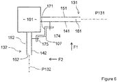
- FIG 6 illustrates an alternative embodiment of the invention.
- mechanical elements similar to those of Figures 2 and 3 are assigned the same reference numbers, increased by 100.
- the closing of the figure 6 differs from that of the preceding figures, in that the two adjacent panels 131 and 132 are not parallel, but perpendicular to each other. These panels are fixed on a pole 101, by means of conventional type which are not described in more detail.
- Each connecting member 107 has two tabs 174 and 175, allowing mounting on a respective plate 141 and 142. This attachment, which is schematically illustrated on this figure 6 , is carried out analogously to what has just been described immediately above for the member 7.
- the two lugs 174 and 175 are connected by an L-shaped transition zone 171, which bypasses the pole 101.
- P131 and P132 respectively denote the main planes of the panels 131 and 132. Within the meaning of the invention, there is no overlap between these two panels 131 and 132. In other words, the latter do not overlap when they are seen, firstly along the arrow F1 perpendicular to the main plane P131 and, secondly, according to the arrow F2 perpendicular to the main plane P132.
Landscapes
- Engineering & Computer Science (AREA)
- Architecture (AREA)
- Civil Engineering (AREA)
- Structural Engineering (AREA)
- Physics & Mathematics (AREA)
- General Physics & Mathematics (AREA)
- Fencing (AREA)
Claims (10)
- Sicherheitszaun, Folgendes umfassend- ein Gerippe, welches Strukturteile (1, 2; 101) umfasst,- zumindest zwei Felder (31-39; 131, 132), wobei jedes Feld zumindest eine erste (41, 42, 44; 141, 142) und eine zweite (51, 52, 54; 151, 152) Platte umfasst, die nebeneinander montiert werden, sowie Mittel (61, 62, 64; 161, 162) zur elektrischen Isolierung zwischen den beiden Platten,- Mittel (MF) zur Befestigung eines jeden Feldes an zumindest einem Strukturelement,- erste Mittel (7, 9; 107) zur elektrischen Verbindung zwischen den ersten Platten (41, 42, 44; 141, 142) zumindest zweier angrenzender Felder (31, 32, 34; 131, 132), wobei sich diese angrenzenden Felder über zwei Hauptebenen (P31, P32, P34; P131, P132) erstrecken, sowie zweite Mittel (8, 10) zur elektrischen Verbindung zwischen den zweiten Platten (51, 52, 54) der besagten zumindest zwei angrenzenden Felder,- Mittel für den Masseanschluss der ersten Platten, wobei diese Platten Masseplatten genannt werden, sowie Mittel für den Phasenanschluss der zweiten Platten, wobei diese Platten Phasenplatten genannt werden,wobei der besagte Zaun dadurch gekennzeichnet ist, dass sich die besagten Felder nicht überlappen, wenn sie in eine Richtung (F, F'; F1, F2) senkrecht zur einen oder der anderen ihrer Hauptebenen (P31, P32, P34; P131 P132) gesehen werden.
- Zaun nach Anspruch 1, wobei sich die angrenzenden Felder über zwei parallele Hauptebenen (P31, P32, P34) erstrecken, und sich im Speziellen die beiden angrenzenden Felder über dieselbe Ebene erstrecken.
- Zaun nach Anspruch 1 oder 2, wobei sich die Kanten (31', 32', 41', 51', 44', 54') der beiden angrenzenden Felder beiderseits des Strukturelements erstrecken.
- Zaun nach einem der vorhergehenden Ansprüche, wobei die Hauptebenen (P31, P32, P34) der beiden angrenzenden Felder (31, 32, 34) durch das Strukturelement (1, 2) hindurchführen.
- Zaun nach einem der vorhergehenden Ansprüche, wobei wobei alle Masseplatten (41, 42, 44; 141, 142) auf einer Seite des Zaunes angeordnet sind, während alle Phasenplatten (51, 52, 54; 151, 152) an der gegenüberliegenden Seite des Zaunes angeordnet sind.
- Zaun nach einem der vorhergehenden Ansprüche, wobei die Mittel zur Verbindung ein Verbindungsorgan (7, 8, 9, 10; 107) umfassen, das eine erste Montagezone (74, 94; 174), im Speziellen zur abnehmbaren Montage an einer Masseplatte (41; 141) oder Phasenplatte (51) umfasst, die einem ersten Feld (31; 131) angehört, sowie eine zweite Montagezone (75, 95; 175), im Speziellen zur abnehmbaren Montage an einer Masseplatte (42; 142) oder Phasenplatte (52), die einem zweiten Feld (32; 132) angehört.
- Zaun nach Anspruch 6, wobei das Verbindungsorgan (7, 8, 9, 10; 107) darüber hinaus eine Übergangszone (71, 72, 73; 171) zwischen den besagten Montagezonen umfasst, wobei sich diese Übergangszone auf Abstand zu den Wänden gegenüber dem Strukturelement (1, 2; 101) erstreckt.
- Zaun nach Anspruch 7, wobei die Übergangszone (71, 72, 73; 171) eine angemessene Form, inbesondere eine U- oder L-Form aufweist, um das Strukturelement (1; 2) zu umgehen.
- Zaun nach Anspruch 7, wobei das Verbindungsorgan eine Leiste (8, 10) ist, deren Übergangszone durch eine Aussparung (P8, P10) führt, die in das Strukturelement (2) eingearbeitet ist.
- Sicherheitszaun, Folgendes umfassend- ein Gerippe, welches Strukturteile (1, 2; 101) umfasst,- zumindest zwei Felder (31-39; 131, 132), wobei jedes Feld zumindest eine erste (41, 42, 44; 141, 142) und eine zweite (51, 52, 54; 151, 152) Platte umfasst, die nebeneinander montiert werden, sowie Mittel (61, 62, 64; 161, 162) zur elektrischen Isolierung zwischen den beiden Platten,- Mittel (MF) zur Befestigung eines jeden Feldes an zumindest einem Strukturelement,- erste Mittel (7, 9; 107) zur elektrischen Verbindung zwischen den ersten Platten (41, 42, 44; 141, 142) zumindest zweier angrenzender Felder (31, 32, 34; 131, 132), sowie zweite Mittel (8, 10) zur elektrischen Verbindung zwischen den zweiten Platten (51, 52, 54) der besagten zumindest zwei angrenzenden Felder,- Mittel für den Masseanschluss der ersten Platten, wobei diese Platten Masseplatten genannt werden, sowie Mittel für den Phasenanschluss der zweiten Platten, wobei diese Platten Phasenplatten genannt werden,dadurch gekennzeichnet, dass die Mittel zur Verbindung ein Verbindungsorgan (10) umfassen, das eine erste Montagezone, im Speziellen zur abnehmbaren Montage an einer Phasen- oder Masseplatte umfasst, die einem ersten Feld angehört, eine zweite Montagezone, im Speziellen zur abnehmbaren Montage an einer Phasen- oder Masseplatte umfasst, die einem zweiten Feld angehört, sowie eine Übergangszone zwischen diesen Montagezonen, wobei sich diese Übergangszone auf Abstand zum Strukturelement erstreckt.
Applications Claiming Priority (1)
| Application Number | Priority Date | Filing Date | Title |
|---|---|---|---|
| FR1462148A FR3029956B1 (fr) | 2014-12-10 | 2014-12-10 | Cloture de securite comprenant plusieurs panneaux fixes sur une ossature |
Publications (2)
| Publication Number | Publication Date |
|---|---|
| EP3032003A1 EP3032003A1 (de) | 2016-06-15 |
| EP3032003B1 true EP3032003B1 (de) | 2017-05-31 |
Family
ID=52737236
Family Applications (1)
| Application Number | Title | Priority Date | Filing Date |
|---|---|---|---|
| EP15196188.5A Active EP3032003B1 (de) | 2014-12-10 | 2015-11-25 | Sicherheitszaun, der mehrere feststehende paneele auf einem skelettbau umfasst |
Country Status (2)
| Country | Link |
|---|---|
| EP (1) | EP3032003B1 (de) |
| FR (1) | FR3029956B1 (de) |
Family Cites Families (5)
| Publication number | Priority date | Publication date | Assignee | Title |
|---|---|---|---|---|
| CH643077A5 (it) * | 1979-08-07 | 1984-05-15 | Ci Ka Ra Srl | Rete di recinzione anti-effrazione, procedimento e dispositivo per la sua fabbricazione. |
| FR2592512A1 (fr) * | 1985-12-31 | 1987-07-03 | Cogny Systems | Cloture electrique de type urbain |
| FR2762919B1 (fr) * | 1997-04-30 | 1999-08-06 | Yves Guerineau | Cloture de securite constituee de treillis conducteurs |
| FR2937360B1 (fr) | 2008-10-20 | 2010-12-24 | Eurocloture | Panneau de cloture de securite et cloture de securite qui est constituee d'au moins un tel panneau |
| AU2011316476A1 (en) * | 2010-10-12 | 2013-04-18 | Qld Security Fencing Pty Ltd | Rapid deployment high security electric fencing |
-
2014
- 2014-12-10 FR FR1462148A patent/FR3029956B1/fr not_active Expired - Fee Related
-
2015
- 2015-11-25 EP EP15196188.5A patent/EP3032003B1/de active Active
Also Published As
| Publication number | Publication date |
|---|---|
| FR3029956A1 (fr) | 2016-06-17 |
| FR3029956B1 (fr) | 2016-12-23 |
| EP3032003A1 (de) | 2016-06-15 |
Similar Documents
| Publication | Publication Date | Title |
|---|---|---|
| EP3323171B1 (de) | Isolator für eine schwenkbare elektrische verbindung | |
| EP2993745B1 (de) | Struktur für eine elektro-anlage eines schienenfahrzeugs, und entsprechendes schienenfahrzeug | |
| WO2014114883A1 (fr) | Assemblage de masselotte d'équilibrage a un élément de rotor | |
| FR3018088A1 (fr) | Dispositif de solidarisation d'un panneau de grillage rigide a un poteau rainure, ledit dispositif comprenant un element de solidarisation comprenant une butee de blocage en translation le long de l'axe longitudinal de la rainure | |
| EP3492675B1 (de) | Vorrichtung zum befestigen von lamellen an einem starren gitterpaneel, lamellenbefestigungskit an einem starren gitterpaneel und sichtschutzzaun, der mit diesem kit ausgestattet ist | |
| EP3997759B1 (de) | Verbindungsvorrichtung zum erden eines elektrischen gerätes und/oder zur erzeugung einer äquipotenzialverbindung zwischen leitenden elementen | |
| FR2804253A1 (fr) | Chemin de cables en fils a haute resistance | |
| EP3032003B1 (de) | Sicherheitszaun, der mehrere feststehende paneele auf einem skelettbau umfasst | |
| EP1793659B1 (de) | Schaltschrank, der eine Verdrahtungshalterung umfasst | |
| EP2233665B1 (de) | Modulkonstruktion | |
| EP2508837A1 (de) | Balistisches Schutzgitter mit einer Zugangsklappe | |
| WO2013088052A1 (fr) | Systeme de liaison equipotentielle pour panneau | |
| FR2993720A1 (fr) | Rampe de support de cables electriques pour aeronef | |
| EP2428449B1 (de) | Vorrichtung für Wärmeisolation und Herstellungsverfahren | |
| EP3006650B1 (de) | Gittervorrichtung zum erstellen eines zauns, und zaun ohne pfosten, der mithilfe einer solchen vorrichtung errichtet wird | |
| FR3023310A1 (fr) | Ecarteur a rupture de pont thermique pour dispositif de construction, son utilisation et dispositif de construction correspondant | |
| EP3238977A1 (de) | Stromversorgungseinheit zum wiederaufladen von elektrischen batterien von elektrofahrzeugen | |
| EP4092226B1 (de) | Stabgitter-element und entsprechender zaun | |
| EP2186956A1 (de) | Montageteil zur Montage eines Modules, insbesondere eines Wohnmodules, Montage, Kit und Modul | |
| WO2006108932A1 (fr) | Batiment prefabrique et ossature pour un tel batiment | |
| EP2178055A1 (de) | Sicherheitsverschlusspaneel und Sicherheitsverschluss, der mindestens aus einem solchen Paneel besteht | |
| EP3490086B1 (de) | Halterungssystem für elektrischen schaltschrank | |
| FR3038638A1 (fr) | Dispositif de chainage, ainsi qu'ensemble de chainage comprenant deux tels dispositifs | |
| EP3077611A1 (de) | Feuerfeste wandtrennvorrichtung sowie wandtrennanordnung mit einer vorgehängten tür und solch einer vorrichtung | |
| FR2963492A1 (fr) | Panneau de fixation pour compteur electrique. |
Legal Events
| Date | Code | Title | Description |
|---|---|---|---|
| PUAI | Public reference made under article 153(3) epc to a published international application that has entered the european phase |
Free format text: ORIGINAL CODE: 0009012 |
|
| AK | Designated contracting states |
Kind code of ref document: A1 Designated state(s): AL AT BE BG CH CY CZ DE DK EE ES FI FR GB GR HR HU IE IS IT LI LT LU LV MC MK MT NL NO PL PT RO RS SE SI SK SM TR |
|
| AX | Request for extension of the european patent |
Extension state: BA ME |
|
| STAA | Information on the status of an ep patent application or granted ep patent |
Free format text: STATUS: REQUEST FOR EXAMINATION WAS MADE |
|
| 17P | Request for examination filed |
Effective date: 20161215 |
|
| RBV | Designated contracting states (corrected) |
Designated state(s): AL AT BE BG CH CY CZ DE DK EE ES FI FR GB GR HR HU IE IS IT LI LT LU LV MC MK MT NL NO PL PT RO RS SE SI SK SM TR |
|
| GRAP | Despatch of communication of intention to grant a patent |
Free format text: ORIGINAL CODE: EPIDOSNIGR1 |
|
| STAA | Information on the status of an ep patent application or granted ep patent |
Free format text: STATUS: GRANT OF PATENT IS INTENDED |
|
| RIC1 | Information provided on ipc code assigned before grant |
Ipc: G08B 13/12 20060101ALI20170112BHEP Ipc: E04H 17/16 20060101AFI20170112BHEP |
|
| INTG | Intention to grant announced |
Effective date: 20170130 |
|
| GRAS | Grant fee paid |
Free format text: ORIGINAL CODE: EPIDOSNIGR3 |
|
| GRAA | (expected) grant |
Free format text: ORIGINAL CODE: 0009210 |
|
| STAA | Information on the status of an ep patent application or granted ep patent |
Free format text: STATUS: THE PATENT HAS BEEN GRANTED |
|
| AK | Designated contracting states |
Kind code of ref document: B1 Designated state(s): AL AT BE BG CH CY CZ DE DK EE ES FI FR GB GR HR HU IE IS IT LI LT LU LV MC MK MT NL NO PL PT RO RS SE SI SK SM TR |
|
| REG | Reference to a national code |
Ref country code: CH Ref legal event code: EP Ref country code: GB Ref legal event code: FG4D Free format text: NOT ENGLISH |
|
| REG | Reference to a national code |
Ref country code: AT Ref legal event code: REF Ref document number: 897625 Country of ref document: AT Kind code of ref document: T Effective date: 20170615 |
|
| REG | Reference to a national code |
Ref country code: IE Ref legal event code: FG4D Free format text: LANGUAGE OF EP DOCUMENT: FRENCH |
|
| REG | Reference to a national code |
Ref country code: DE Ref legal event code: R096 Ref document number: 602015002919 Country of ref document: DE |
|
| REG | Reference to a national code |
Ref country code: NL Ref legal event code: MP Effective date: 20170531 |
|
| REG | Reference to a national code |
Ref country code: LT Ref legal event code: MG4D |
|
| REG | Reference to a national code |
Ref country code: AT Ref legal event code: MK05 Ref document number: 897625 Country of ref document: AT Kind code of ref document: T Effective date: 20170531 |
|
| PG25 | Lapsed in a contracting state [announced via postgrant information from national office to epo] |
Ref country code: ES Free format text: LAPSE BECAUSE OF FAILURE TO SUBMIT A TRANSLATION OF THE DESCRIPTION OR TO PAY THE FEE WITHIN THE PRESCRIBED TIME-LIMIT Effective date: 20170531 Ref country code: HR Free format text: LAPSE BECAUSE OF FAILURE TO SUBMIT A TRANSLATION OF THE DESCRIPTION OR TO PAY THE FEE WITHIN THE PRESCRIBED TIME-LIMIT Effective date: 20170531 Ref country code: AT Free format text: LAPSE BECAUSE OF FAILURE TO SUBMIT A TRANSLATION OF THE DESCRIPTION OR TO PAY THE FEE WITHIN THE PRESCRIBED TIME-LIMIT Effective date: 20170531 Ref country code: LT Free format text: LAPSE BECAUSE OF FAILURE TO SUBMIT A TRANSLATION OF THE DESCRIPTION OR TO PAY THE FEE WITHIN THE PRESCRIBED TIME-LIMIT Effective date: 20170531 Ref country code: NO Free format text: LAPSE BECAUSE OF FAILURE TO SUBMIT A TRANSLATION OF THE DESCRIPTION OR TO PAY THE FEE WITHIN THE PRESCRIBED TIME-LIMIT Effective date: 20170831 Ref country code: GR Free format text: LAPSE BECAUSE OF FAILURE TO SUBMIT A TRANSLATION OF THE DESCRIPTION OR TO PAY THE FEE WITHIN THE PRESCRIBED TIME-LIMIT Effective date: 20170901 Ref country code: FI Free format text: LAPSE BECAUSE OF FAILURE TO SUBMIT A TRANSLATION OF THE DESCRIPTION OR TO PAY THE FEE WITHIN THE PRESCRIBED TIME-LIMIT Effective date: 20170531 |
|
| REG | Reference to a national code |
Ref country code: FR Ref legal event code: PLFP Year of fee payment: 3 |
|
| PG25 | Lapsed in a contracting state [announced via postgrant information from national office to epo] |
Ref country code: RS Free format text: LAPSE BECAUSE OF FAILURE TO SUBMIT A TRANSLATION OF THE DESCRIPTION OR TO PAY THE FEE WITHIN THE PRESCRIBED TIME-LIMIT Effective date: 20170531 Ref country code: BG Free format text: LAPSE BECAUSE OF FAILURE TO SUBMIT A TRANSLATION OF THE DESCRIPTION OR TO PAY THE FEE WITHIN THE PRESCRIBED TIME-LIMIT Effective date: 20170831 Ref country code: LV Free format text: LAPSE BECAUSE OF FAILURE TO SUBMIT A TRANSLATION OF THE DESCRIPTION OR TO PAY THE FEE WITHIN THE PRESCRIBED TIME-LIMIT Effective date: 20170531 Ref country code: SE Free format text: LAPSE BECAUSE OF FAILURE TO SUBMIT A TRANSLATION OF THE DESCRIPTION OR TO PAY THE FEE WITHIN THE PRESCRIBED TIME-LIMIT Effective date: 20170531 Ref country code: IS Free format text: LAPSE BECAUSE OF FAILURE TO SUBMIT A TRANSLATION OF THE DESCRIPTION OR TO PAY THE FEE WITHIN THE PRESCRIBED TIME-LIMIT Effective date: 20170930 Ref country code: NL Free format text: LAPSE BECAUSE OF FAILURE TO SUBMIT A TRANSLATION OF THE DESCRIPTION OR TO PAY THE FEE WITHIN THE PRESCRIBED TIME-LIMIT Effective date: 20170531 |
|
| PG25 | Lapsed in a contracting state [announced via postgrant information from national office to epo] |
Ref country code: RO Free format text: LAPSE BECAUSE OF FAILURE TO SUBMIT A TRANSLATION OF THE DESCRIPTION OR TO PAY THE FEE WITHIN THE PRESCRIBED TIME-LIMIT Effective date: 20170531 Ref country code: DK Free format text: LAPSE BECAUSE OF FAILURE TO SUBMIT A TRANSLATION OF THE DESCRIPTION OR TO PAY THE FEE WITHIN THE PRESCRIBED TIME-LIMIT Effective date: 20170531 Ref country code: EE Free format text: LAPSE BECAUSE OF FAILURE TO SUBMIT A TRANSLATION OF THE DESCRIPTION OR TO PAY THE FEE WITHIN THE PRESCRIBED TIME-LIMIT Effective date: 20170531 Ref country code: SK Free format text: LAPSE BECAUSE OF FAILURE TO SUBMIT A TRANSLATION OF THE DESCRIPTION OR TO PAY THE FEE WITHIN THE PRESCRIBED TIME-LIMIT Effective date: 20170531 Ref country code: CZ Free format text: LAPSE BECAUSE OF FAILURE TO SUBMIT A TRANSLATION OF THE DESCRIPTION OR TO PAY THE FEE WITHIN THE PRESCRIBED TIME-LIMIT Effective date: 20170531 |
|
| PG25 | Lapsed in a contracting state [announced via postgrant information from national office to epo] |
Ref country code: IT Free format text: LAPSE BECAUSE OF FAILURE TO SUBMIT A TRANSLATION OF THE DESCRIPTION OR TO PAY THE FEE WITHIN THE PRESCRIBED TIME-LIMIT Effective date: 20170531 Ref country code: SM Free format text: LAPSE BECAUSE OF FAILURE TO SUBMIT A TRANSLATION OF THE DESCRIPTION OR TO PAY THE FEE WITHIN THE PRESCRIBED TIME-LIMIT Effective date: 20170531 Ref country code: PL Free format text: LAPSE BECAUSE OF FAILURE TO SUBMIT A TRANSLATION OF THE DESCRIPTION OR TO PAY THE FEE WITHIN THE PRESCRIBED TIME-LIMIT Effective date: 20170531 |
|
| REG | Reference to a national code |
Ref country code: DE Ref legal event code: R097 Ref document number: 602015002919 Country of ref document: DE |
|
| PLBE | No opposition filed within time limit |
Free format text: ORIGINAL CODE: 0009261 |
|
| STAA | Information on the status of an ep patent application or granted ep patent |
Free format text: STATUS: NO OPPOSITION FILED WITHIN TIME LIMIT |
|
| 26N | No opposition filed |
Effective date: 20180301 |
|
| PG25 | Lapsed in a contracting state [announced via postgrant information from national office to epo] |
Ref country code: SI Free format text: LAPSE BECAUSE OF FAILURE TO SUBMIT A TRANSLATION OF THE DESCRIPTION OR TO PAY THE FEE WITHIN THE PRESCRIBED TIME-LIMIT Effective date: 20170531 |
|
| PG25 | Lapsed in a contracting state [announced via postgrant information from national office to epo] |
Ref country code: MC Free format text: LAPSE BECAUSE OF FAILURE TO SUBMIT A TRANSLATION OF THE DESCRIPTION OR TO PAY THE FEE WITHIN THE PRESCRIBED TIME-LIMIT Effective date: 20170531 |
|
| PG25 | Lapsed in a contracting state [announced via postgrant information from national office to epo] |
Ref country code: LU Free format text: LAPSE BECAUSE OF NON-PAYMENT OF DUE FEES Effective date: 20171125 |
|
| REG | Reference to a national code |
Ref country code: IE Ref legal event code: MM4A |
|
| PG25 | Lapsed in a contracting state [announced via postgrant information from national office to epo] |
Ref country code: MT Free format text: LAPSE BECAUSE OF FAILURE TO SUBMIT A TRANSLATION OF THE DESCRIPTION OR TO PAY THE FEE WITHIN THE PRESCRIBED TIME-LIMIT Effective date: 20170531 |
|
| PG25 | Lapsed in a contracting state [announced via postgrant information from national office to epo] |
Ref country code: IE Free format text: LAPSE BECAUSE OF NON-PAYMENT OF DUE FEES Effective date: 20171125 |
|
| PG25 | Lapsed in a contracting state [announced via postgrant information from national office to epo] |
Ref country code: HU Free format text: LAPSE BECAUSE OF FAILURE TO SUBMIT A TRANSLATION OF THE DESCRIPTION OR TO PAY THE FEE WITHIN THE PRESCRIBED TIME-LIMIT; INVALID AB INITIO Effective date: 20151125 |
|
| PG25 | Lapsed in a contracting state [announced via postgrant information from national office to epo] |
Ref country code: CY Free format text: LAPSE BECAUSE OF FAILURE TO SUBMIT A TRANSLATION OF THE DESCRIPTION OR TO PAY THE FEE WITHIN THE PRESCRIBED TIME-LIMIT Effective date: 20170531 |
|
| PG25 | Lapsed in a contracting state [announced via postgrant information from national office to epo] |
Ref country code: MK Free format text: LAPSE BECAUSE OF FAILURE TO SUBMIT A TRANSLATION OF THE DESCRIPTION OR TO PAY THE FEE WITHIN THE PRESCRIBED TIME-LIMIT Effective date: 20170531 |
|
| PG25 | Lapsed in a contracting state [announced via postgrant information from national office to epo] |
Ref country code: TR Free format text: LAPSE BECAUSE OF FAILURE TO SUBMIT A TRANSLATION OF THE DESCRIPTION OR TO PAY THE FEE WITHIN THE PRESCRIBED TIME-LIMIT Effective date: 20170531 |
|
| PG25 | Lapsed in a contracting state [announced via postgrant information from national office to epo] |
Ref country code: PT Free format text: LAPSE BECAUSE OF FAILURE TO SUBMIT A TRANSLATION OF THE DESCRIPTION OR TO PAY THE FEE WITHIN THE PRESCRIBED TIME-LIMIT Effective date: 20170531 |
|
| PG25 | Lapsed in a contracting state [announced via postgrant information from national office to epo] |
Ref country code: AL Free format text: LAPSE BECAUSE OF FAILURE TO SUBMIT A TRANSLATION OF THE DESCRIPTION OR TO PAY THE FEE WITHIN THE PRESCRIBED TIME-LIMIT Effective date: 20170531 |
|
| GBPC | Gb: european patent ceased through non-payment of renewal fee |
Effective date: 20191125 |
|
| PG25 | Lapsed in a contracting state [announced via postgrant information from national office to epo] |
Ref country code: GB Free format text: LAPSE BECAUSE OF NON-PAYMENT OF DUE FEES Effective date: 20191125 |
|
| PGFP | Annual fee paid to national office [announced via postgrant information from national office to epo] |
Ref country code: DE Payment date: 20241206 Year of fee payment: 10 |
|
| PGFP | Annual fee paid to national office [announced via postgrant information from national office to epo] |
Ref country code: CH Payment date: 20241201 Year of fee payment: 10 |
|
| REG | Reference to a national code |
Ref country code: CH Ref legal event code: U11 Free format text: ST27 STATUS EVENT CODE: U-0-0-U10-U11 (AS PROVIDED BY THE NATIONAL OFFICE) Effective date: 20260108 |
|
| PGFP | Annual fee paid to national office [announced via postgrant information from national office to epo] |
Ref country code: FR Payment date: 20251119 Year of fee payment: 11 |
|
| PGFP | Annual fee paid to national office [announced via postgrant information from national office to epo] |
Ref country code: BE Payment date: 20251127 Year of fee payment: 11 |