EP3031756B2 - Linear drive transport system and method - Google Patents
Linear drive transport system and method Download PDFInfo
- Publication number
- EP3031756B2 EP3031756B2 EP15197911.9A EP15197911A EP3031756B2 EP 3031756 B2 EP3031756 B2 EP 3031756B2 EP 15197911 A EP15197911 A EP 15197911A EP 3031756 B2 EP3031756 B2 EP 3031756B2
- Authority
- EP
- European Patent Office
- Prior art keywords
- track
- linear drive
- tracks
- junction
- conveyor
- Prior art date
- Legal status (The legal status is an assumption and is not a legal conclusion. Google has not performed a legal analysis and makes no representation as to the accuracy of the status listed.)
- Active
Links
Images


Classifications
-
- B—PERFORMING OPERATIONS; TRANSPORTING
- B65—CONVEYING; PACKING; STORING; HANDLING THIN OR FILAMENTARY MATERIAL
- B65G—TRANSPORT OR STORAGE DEVICES, e.g. CONVEYORS FOR LOADING OR TIPPING, SHOP CONVEYOR SYSTEMS OR PNEUMATIC TUBE CONVEYORS
- B65G54/00—Non-mechanical conveyors not otherwise provided for
- B65G54/02—Non-mechanical conveyors not otherwise provided for electrostatic, electric, or magnetic
-
- B—PERFORMING OPERATIONS; TRANSPORTING
- B65—CONVEYING; PACKING; STORING; HANDLING THIN OR FILAMENTARY MATERIAL
- B65G—TRANSPORT OR STORAGE DEVICES, e.g. CONVEYORS FOR LOADING OR TIPPING, SHOP CONVEYOR SYSTEMS OR PNEUMATIC TUBE CONVEYORS
- B65G47/00—Article or material-handling devices associated with conveyors; Methods employing such devices
- B65G47/52—Devices for transferring articles or materials between conveyors i.e. discharging or feeding devices
- B65G47/64—Switching conveyors
- B65G47/641—Switching conveyors by a linear displacement of the switching conveyor
- B65G47/642—Switching conveyors by a linear displacement of the switching conveyor in a horizontal plane
-
- B—PERFORMING OPERATIONS; TRANSPORTING
- B65—CONVEYING; PACKING; STORING; HANDLING THIN OR FILAMENTARY MATERIAL
- B65G—TRANSPORT OR STORAGE DEVICES, e.g. CONVEYORS FOR LOADING OR TIPPING, SHOP CONVEYOR SYSTEMS OR PNEUMATIC TUBE CONVEYORS
- B65G47/00—Article or material-handling devices associated with conveyors; Methods employing such devices
- B65G47/52—Devices for transferring articles or materials between conveyors i.e. discharging or feeding devices
- B65G47/64—Switching conveyors
- B65G47/641—Switching conveyors by a linear displacement of the switching conveyor
- B65G47/643—Switching conveyors by a linear displacement of the switching conveyor in a vertical plane
-
- B—PERFORMING OPERATIONS; TRANSPORTING
- B65—CONVEYING; PACKING; STORING; HANDLING THIN OR FILAMENTARY MATERIAL
- B65G—TRANSPORT OR STORAGE DEVICES, e.g. CONVEYORS FOR LOADING OR TIPPING, SHOP CONVEYOR SYSTEMS OR PNEUMATIC TUBE CONVEYORS
- B65G47/00—Article or material-handling devices associated with conveyors; Methods employing such devices
- B65G47/52—Devices for transferring articles or materials between conveyors i.e. discharging or feeding devices
- B65G47/64—Switching conveyors
- B65G47/644—Switching conveyors by a pivoting displacement of the switching conveyor
- B65G47/648—Switching conveyors by a pivoting displacement of the switching conveyor about a vertical axis
-
- B—PERFORMING OPERATIONS; TRANSPORTING
- B65—CONVEYING; PACKING; STORING; HANDLING THIN OR FILAMENTARY MATERIAL
- B65G—TRANSPORT OR STORAGE DEVICES, e.g. CONVEYORS FOR LOADING OR TIPPING, SHOP CONVEYOR SYSTEMS OR PNEUMATIC TUBE CONVEYORS
- B65G54/00—Non-mechanical conveyors not otherwise provided for
- B65G54/02—Non-mechanical conveyors not otherwise provided for electrostatic, electric, or magnetic
- B65G54/025—Non-mechanical conveyors not otherwise provided for electrostatic, electric, or magnetic the load being magnetically coupled with a piston-like driver moved within a tube
Definitions
- the present disclosure is generally directed to linear drive transport systems and methods of positioning movers in a linear drive transport system.
- a linear drive or linear motor generally includes an electromagnetic device that operates to provide motion along a path or "linear motion" rather than the rotary motion typically provided by a standard electric motor.
- a linear drive typically produces electromotive force in a conductor by changing a magnetic field about the conductor.
- linear drives generally function based on interactions between electromagnets and permanent magnets. Coils of the electromagnets can be charged to create magnetic fields that interact with permanent magnets to provide motion.
- moving magnet linear drive the coils are fixed within a track or track segments and movers along the track include permanent magnets.
- moving magnet linear drives allow for unpowered movers whereas moving coil linear drives generally require that power be provided to the electromagnet on each mover.
- moving coil linear drives are often capable of greater movement precision for the movers than moving magnet linear drives.
- Linear drives are often used in transport systems that facilitate different types of industrial operations.
- linear drive transport systems may be utilized to convey products to different areas in a manufacturing or packaging operation.
- most linear drives include straight or circular tracks. This has caused limited employment of linear drives due to a lack of versatility in traditional arrangements. It is now recognized that it is desirable to have more versatility in conveyance paths for linear drives in certain industrial operations.
- WO 2010/085670 A1 relates to a linear drive transport system powered by short block linear synchronized motors (LSMs).
- LSM-based transport system allows vehicles to move on a guideway that can be complex and that can include sharp horizontal and vertical turns, merge and diverge switching, and inverted operation.
- the vehicles can include wheels or can operate without wheels and slide on a guideway's running surface.
- the structure of the guideway provides guidance in one or more dimensions.
- the vehicles include permanent magnets arranged in magnet arrays.
- the guideways include coils mounted in close proximity to the guideway running surface. The coils are individually controlled so that each vehicle can be individually controlled even if touching neighboring vehicles.
- One element of a guideway can be a turntable. Guidance rails on the turntable and propulsion coils guide and propel the vehicle. This document also relates to a method of positioning movers in a linear drive transport system.
- JP 2004/15894 A relates to a linear motor in which a modular stator can be rotated, parallel and vertically moved with a mover module thereon.
- a Linear motor includes a rotatable stator, a plurality of fixed stators and a mover configured to move along the stators.
- the mover is provided with a permanent magnet and each stator is constituted by connecting a plurality of modules divided in unit length in the longitudinal direction, wherein each module includes a coil.
- the rotatable stator is attached to a shaft that is rotated by a motor.
- the mover arrives at the rotatable stator from a fixed stator and is stopped.
- the rotatable stator is rotated by a desired angle such that the rotatable stator faces another fixed stator.
- the document further shows a linear motor with a movable stator that is movable in a horizontal direction.
- the fixed stators and the movable stator are arranged in a horizontal plane.
- a well-known moving device can be used as a mechanism for translating the movable stator in parallel.
- the mover arrives from a fixed stator at the movable stator and is stopped.
- the movable stator is moved in parallel.
- the moveable stator faces another fixed stator, the movable stator is stopped. Thereafter, the mover moves from the movable stator to the other fixed stator.
- Present embodiments include a linear drive transport system.
- the system includes a plurality of fixed tracks and a junction track disposed on a conveyor configured to align the junction track with each of the plurality of fixed tracks.
- the plurality of fixed tracks and the junction track include electromagnetic coils or permanent magnets arranged in series along the respective plurality of fixed tracks and the junction track.
- present embodiments include a plurality of movers configured to move along the fixed tracks and configured to transition between each of the plurality of fixed tracks and the junction track when aligned, wherein the movers comprise the other of the electromagnetic coils or the permanent magnets.
- the junction track is configured to receive a mover from a first fixed track and to impel the mover onto a second fixed track after being repositioned into alignment with the second fixed track by the conveyor.
- Present embodiments also include a shuttle system for a linear drive transport system.
- the shuttle system includes a conveyor configured to move along a path that is transverse to a plurality of linear drive tracks that are configured to transport a linear drive mover in one of a moving magnet configuration or a moving coil configuration.
- the shuttle system includes a junction track disposed on the conveyor, wherein the junction track is configured to transport the linear drive mover in the same one of the moving magnet configuration or the moving coil configuration as the plurality of linear drive tracks.
- the conveyor is configured to align the junction track with at least a subset of the plurality of linear drive tracks to facilitate transfer of the linear drive mover there between.
- the junction track is configured to receive the linear drive mover from a first linear drive track track and to impel the mover onto a second linear drive track after being repositioned into alignment with the second linear drive track by the conveyor.
- Present embodiments also include a method of positioning movers in a linear drive transport system.
- the method includes aligning a junction track with a first fixed track of a plurality of fixed tracks by moving the junction track with a conveyor comprising a linear drive on which the junction track is disposed. Further, the method includes impelling at least one mover along the first fixed track, transitioning the at least one mover from the first fixed track to the junction track, aligning the junction track with a second fixed track of the plurality of fixed tracks using the conveyor, and transitioning the at least one mover to the second fixed track under the influence of electromagnetic force resulting from interaction between at least one electromagnet coil and at least one permanent magnet.
- a linear drive transport system employs linear drives that utilize principles of electromagnetic propulsion to transport movers along a track.
- the linear drive transport system may employ a moving magnet configuration or a moving coil configuration. In both configurations, movers are impelled under the influence of electromagnetic force resulting from interaction between two electromagnetic fields (e.g., interaction between one or more electromagnetic coils and one or more permanent magnets).
- a mover may include an array of permanent magnets that are forced along as a result of interaction between magnetic fields of the array and magnetic fields generated by electromagnet coils in a track.
- a mover may include one or more electromagnet coils and a track may include permanent magnets that cooperate to impel the mover along the track.
- different combinations of magnets may be used (e.g., electromagnets alone may be used).
- the tracks utilized in linear drive transport systems are essentially configured in a straight line or loop (e.g., oval) configurations. It is now recognized that these traditional track configurations often make it difficult to pass articles (e.g., products being transported) along variable paths and to transfer articles between paths.
- articles e.g., products being transported
- the ability to divert an article from a central path to one of several diverging paths may require the use of pucks and complicated track switching mechanisms, wherein the pucks are movers that are not physically attached to the track and thus free to move from a central path to any of several diverging paths that extend from the central path.
- this type of configuration may lack sufficient stability and positional accuracy for certain operations.
- diverging paths typically require paths that have curves, which can complicate system assembly.
- tracks typically comprise laminates that are assembled to form the tracks. If a curved track is desired, specially designed laminate assemblies may be required, which it is now recognized can cause substantial inefficiencies in system manufacturing and assembly.
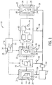
- FIG. 1 is a schematic representation of a linear drive transport system (LDT system) 10 in accordance with present embodiments.
- the LDT system 10 includes a plurality of shuttle systems 12 that facilitate transfer of a mover body 14, which is representative of a central physical structure of one or a plurality of movers 16, between separate tracks 18 of the LDT system 10.
- the mover 16 and any associated article (e.g., products disposed on or otherwise engaged by the mover 16) being transported by the LDT system 10 may be merged onto a single track from multiple tracks, diverted to separate tracks from a single track, or otherwise maneuvered throughout a system of tracks (e.g., tracks 18).
- the mover 16 may be positioned along any of the various tracks 18 or on any of the various shuttle systems 12 at certain points during system operation.
- the mover or movers 16 are schematically represented in FIG. 1 as capable of being positioned at various locations throughout the LDT system 10.
- each of a plurality of movers 16 may be positioned at different locations throughout the LDT system 10.
- the shuttle systems 12 are each illustrated as including one or more junction tracks 20, which generally operate in the same manner as the plurality of tracks 18 they interact with. That is, the junction tracks 20 may employ one of permanent magnets 22 or electromagnet coils 24 to interact with the other of permanent magnets 22 or electromagnet coils 24 in the movers 16 to provide motivation along the tracks 18 and junction tracks 20 using electromagnetic force.
- the tracks 18 and the junction tracks 20 operate with the movers 16 as a linear drive in a moving magnet configuration.
- the mover body 14 is illustrated as including the permanent magnet (e.g., an array of permanent magnets) 22, while the tracks 18 and junction tracks 20 are illustrated as including the electromagnet coils 24.
- the mover body 14 may include the electromagnet coils 24, while the tracks 18 and junction tracks 20 include the permanent magnets 22.
- the junction tracks 20 are each disposed on a shuttle mover 26 of the corresponding shuttle system 12, wherein the shuttle mover 26 is disposed on, coordinates with, or incorporates a conveyor 28 of the corresponding shuttle system 12.
- the junction track 20 is disposed on the shuttle mover 26 in such a way as to be essentially integral therewith and the junction track 20 basically functions as both the shuttle mover 26 and the junction track 20.
- the junction track 20 is disposed on but delineated as separate from the shuttle mover 26.
- the junction track 20 may be disposed on a surface of a conveyor belt, wherein the belt surface is considered a mover 26 of the shuttle system 12 and an associated drive mechanism (e.g., chain) of the conveyor belt is considered the conveyor 28 of the shuttle system 12.
- the conveyor 28 may also include a rotary table, a linear drive, or other types of conveyance mechanisms in accordance with present embodiments.
- the shuttle mover 26 on which the junction track 20 is disposed is a shuttle mover 26 of a linear drive system that is in a moving magnet configuration or a moving coil configuration and functioning as the conveyor 28. More specifically, in such an embodiment, the shuttle mover 26 and an associated track of the linear drive system may cooperate to function as the conveyor 28.
- the junction track 20 may be disposed on the shuttle mover 26 in a manner that makes it integral with the shuttle mover 26 such that a single component is both the junction track 20 and the shuttle mover 26.
- the shuttle systems 12 may incorporate more than one junction track 20 on each shuttle mover 26. Further, multiple shuttle movers 26 may be positioned on one conveyor in a shuttle system 12. Further still, a single shuttle system 12 may include multiple conveyors 28.
- the shuttle movers 26 and conveyors 28 of the shuttle systems 12 that maneuver the junction tracks 20 are configured to align the respective junction tracks 20 with one of a plurality of other tracks (e.g. fixed tracks 18) to facilitate transfer of movers 16 there between. Accordingly, the movers 16 (and articles being moved) can be maneuvered to different locations throughout the LDT system 10 for processing or warehousing.
- certain tracks 18 may be considered components of particular system modules 30 and these system modules 30 may include certain process features 32 that the movers 16 interact with by traveling along specific tracks in the system module 30.
- the mover 16 may be directed along particular tracks 18 in the system module 30 such that it passes through a process feature 32 (e.g., an oven, a rinse chamber, a deposition chamber, a packaging robot) and facilitates processing of an article being carried by the mover 16.
- the mover 16 may be directed along a particular path 18 through such a process feature 32 and then transitioned by a shuttle system 12 to a different path 18 in the system module for interaction with a different process feature 32.
- a process feature 32 e.g., an oven, a rinse chamber, a deposition chamber, a packaging robot
- the mover 16 may be directed along a particular path 18 through such a process feature 32 and then transitioned by a shuttle system 12 to a different path 18 in the system module for interaction with a different process feature 32.
- such features may be utilized to transfer articles to particular areas for warehousing.
- present embodiments may monitor the mover 16 using tags 36 and tag detectors 38.
- a tag 36 e.g., a bar code, RFID tag, text capable of being identified by Optical Character Recognition (OCR)
- OCR Optical Character Recognition
- the detectors 38 may be positioned proximate exits and entries to tracks 18 and junction tracks 20.
- the detectors 38 may include bar code readers, an OCR system, or RFID detectors positioned adjacent, positioned over, or integrated into the tracks 18 or junction tracks 20 in an orientation that facilitates detection of the tags 36 as they pass near the movers 16.
- Information detected or accumulated in this way may be communicated to a supervisory controller 40 to facilitate tracking of mover locations within the system, determining where movers 16 should proceed for further processing, tracking batches and serialization, and so forth.
- the supervisory controller 40 may interact with the position feedback board 34 to further identify or confirm mover locations and to facilitate positional control.
- FIG. 2 is a perspective view of a portion of an LDT system 10 in accordance with present embodiments.
- the LDT system 10 of FIG. 2 includes a pair of fixed tracks 18 and a shuttle system 12 configured to maneuver movers 16.
- the tracks 18 are linear drive tracks configured for operation in a moving magnet configuration.
- the junction track 20 is essentially identical to a segment of the fixed tracks 18 but positioned on (e.g., integral with) a shuttle mover 26 of a linear drive configured for operation in a moving coil configuration.
- the shuttle system 12 of FIG. 2 includes a conveyor 28 defined by the shuttle mover 26 supporting the junction track 20 and a rail 50 including a series of embedded permanent magnets 52.
- the conveyor 28 further includes a tether 54 for providing power to the shuttle mover 26 from a corresponding power supply 56.
- the junction track 20 is in the process of being aligned with the one of the fixed tracks 18 on which the movers 16 are positioned, as illustrated by arrow 60.
- the conveyor 28 properly aligns the junction track 20 and the track 18, at least one of the movers 16 may be transitioned onto the junction track 20 from the track 18. More specifically, a mover 16 is impelled from the fixed track 18 onto the junction track 20 using electromagnetic forces generated using principles of induction.
- a moving coil configuration for the conveyor 28 (as illustrated), which may facilitate more finely controlled positioning than is typically available using a moving magnet linear drive configuration.
- different configurations may be employed.
- the junction track 20 may also coordinate with the mover 16 to impel it onto the other track 18 after the conveyor 28 repositions the junction track 20 into alignment therewith.
- other tracks 18 may already be in alignment with the track 18 from which the mover 16 is being transferred such that the junction track 20 operates much like a gateway.
- segments of track 18 may be utilized as places for parking movers 16 until it is desirable to reposition them.
- the conveyor 28 that maneuvers the junction track 20 generally operates to move the junction track 20 in a direction that is transverse to the direction a mover 16 will travel on the tracks 18 (e.g., fixed tracks) that the junction track 20 is interacting with.
- This may include moving in one or more directions (e.g., horizontally, vertically, angled) relative to the tracks 18.
- the tracks 18 and shuttle system 12 are linear and positioned cross-wise to one another.
- the system 10 is configured such that movers 16 may pass from one of the tracks 18 onto the junction track 20 by passing over a side of the junction track 20 facing the one of the tracks 18 and then exit onto one of the tracks 18 by passing across the same side of the junction track 20.
- FIG. 3 is a schematic, perspective view of one embodiment of the LDT system 10 in accordance with the present disclosure.
- the LDT system 10 of FIG. 3 includes a plurality of fixed tracks 18 that may coordinate with movers 16 in a moving magnet orientation.
- the shuttle systems 12 in FIG. 3 include junction tracks 20 that coordinate with the movers 16 in a moving magnet configuration to facilitate transfer of the movers 16 between the tracks 18.
- different configurations may be used.
- combinations of moving magnet and moving coil configurations may be employed.
- the shuttle systems 12 may employ any of various and mixed configurations in accordance with present embodiments. For example, some or all of the shuttle systems 12 in the embodiment illustrated by FIG.
- junction track 20 is the moving magnet while also being a electromagnetic track for the movers 16.
- some or all of the shuttle systems 12 may include traditional belt systems or turntables as components for maneuvering the junction track 20, which operates with the movers 16 in a linear drive configuration (e.g., moving magnet or moving coil configuration).
- four of the tracks 18, as indicated by reference numeral 70 are positioned between two inner sets of shuttle systems 12, which are indicated by reference numeral 72. Additional tracks 18, as indicated by reference numeral 74, are positioned outside of the inner shuttle systems 72 and between outer shuttle systems 12, as indicated by reference numeral 76. Further, one of the fixed tracks 18, as indicated by reference numeral 78, provides what may be considered a bypass around the other tracks 70, 74 and directly between the outer shuttle systems 76.
- the four tracks 70 may be configured to facilitate interaction between payloads (articles being carried by movers 16 positioned on the tracks 70) and certain process features 32 (not shown) configured to perform acts on the payloads.
- the inner shuttle systems 72 may facilitate transferring the movers 16 between the various tracks 18 and to the outer shuttle systems 76.
- certain products may be moved along one of the tracks 70 in a first direction, transferred to a second of the tracks 70 by an inner shuttle system 72, and then moved along the second of the tracks 70 in a direction opposite to the first direction. This may be done to pass the payloads through certain process features 32 to achieve an end goal for the products.
- the fixed track 78 may be used to bypass all of the four tracks 70, which may allow for processing payloads along each of the four tracks 70 in the same direction.
- Some of the tracks 18, such as the additional tracks 74 may be utilized as holding areas or areas for parking movers 16 during certain phases or transitions in processing.
- FIG. 3 generally illustrates pathways (tracks 18) that are aligned within the same plane and in parallel.
- geometric terms such as “parallel” and “perpendicular” are presently utilized to facilitate general discussion of geometric orientations and should not be understood as requiring a precise mathematical relationship that would be essentially unattainable in a practical application.
- the shuttle systems 12 of FIG. 3 operate to move the junction tracks 20 in a direction perpendicular to the tracks 18. This may be beneficial and present embodiments include systems wherein only tracks 18 in parallel arrangements or parallel and perpendicular arrangements or utilized to facilitate transfer between tracks using operations along straight lines.
- the junction tracks 20 may be moved in other manners to traverse the tracks 18 and facilitate transitioning of movers 16 to other tracks.
- the tracks 18 may not be straight lines but curved lines.
- FIG. 4 illustrates a schematic, overhead view of a shuttle system 12 interacting with three tracks 18 that may include curved portions.
- the shuttle system 12 includes a turntable 82 that rotates (as indicated by arrow 84) about an axis 86 such that the junction track 20 can be aligned with each of the tracks 18.
- the mover 16 can be received onto the junction track 20, the junction track 20 can be repositioned by the turntable 82 into alignment with another of the tracks 18, and the mover 16 can be transitioned to the other track 18.
- the force used to transition the mover 16 from the track 18 to the junction track 20 and from the junction track 20 to the track 18 may be generated from interactions between magnets and electromagnets, as discussed above.
- the shuttle system 12 is configured such that the mover 16 enters the junction track 20 from a particular side of the junction track 20 and exits from the same side of the junction track 20.
- FIG. 5 is a schematic, perspective view of the LDT system 10 in accordance with and embodiment of the present disclosure.
- the embodiment illustrated in FIG. 5 includes a first track group 102 arranged in a first plane of operation, a second track group 104 arranged in a second plane of operation, a dual-axis shuttle system 106, a mover 16 supporting an article 108, and a supervisory control system 110.
- the mover 16 may be configured to physically attach with the various tracks 18 and the junction track 20 (e.g., a carriage with engagement arms and wheels) or configured to sit on top of the various tracks 18 and the junction track 20 (e.g., a puck that moves along a path without physically coupling).
- the dual-axis shuttle system 106 includes a vertical linear drive 112 and a horizontal linear drive 114. These linear drives 112, 114 may operate in a moving magnet or moving coil configuration.
- the dual-axis shuttle system 106 is configured to facilitate transfer of the mover 16 and any payload it is carrying (e.g., the article 108) within and between the first and second track groups 102, 104. In the illustrated embodiment, this is achieved by supporting the junction track 20 on a shuttle mover 116 disposed on a horizontal track 118 of the horizontal linear drive 114, which is supported by a vertical shuttle mover 120 on a vertical track 122 of the vertical linear drive 112.
- the vertical linear drive 112 includes the vertical track 122 and the vertical shuttle mover 120
- the horizontal linear drive 114 includes the horizontal track 118 and the shuttle mover 116.
- the vertical linear drive 112 enables transport of the mover 16 along a vertical axis, as indicated by arrow 132
- the horizontal drive 114 enables transport of the mover 16 along a horizontal axis, as indicated by arrow 134.
- the vertical and horizontal linear drives 112, 114 may include other types of conveyors (e.g., a chain conveyor, a belt conveyor, a rotary table).
- this may include the use of multiple vertical and horizontal linear drives 112, 114, which may use the same vertical track 122 or multiple horizontal tracks 118 on the same shuttle movers 116, 120. Further, in other embodiments, different configurations may facilitate transfer of the mover 16 along an angled or curved axis and certain tracks 18 may include curves.
- the vertical track 122 may be a vertical segment of a loop track.
- Present embodiments may include the position feedback board 34, which may represent a plurality of such boards and encoder systems, to allow for control and monitoring of paths by representing each mover 16 disposed on a track 18 as a linear axis in a control system.
- the feedback board 34 may be configured to employ magnetic feedback created by the interaction of movers and track segments to achieve this tracking and control function. Transfer from one track 18 to a junction track 20 could be handled by commanding an axis (a mover 16) to the end of the track 18 on which it is disposed after aligning the end of the track 18 with the junction track 20. At the end of the track 18, the axis would be identified in the encoder system of the beginning of the junction track 20 and the axis could be commanded to transfer from the track 18 to the junction track 20.
- the ability to move articles 108 with movers 16 into different operational planes and in different directions with the shuttle system or systems 12 and tracks 18 may facilitate numerous different industrial processes, including processing and warehousing operations. Indeed, present embodiments are directed to smart warehousing and tracking operations for certain processes.
- the embodiment illustrated by FIG. 5 includes the supervisory controller 110, which coordinates with sensors 152, which may represent tag detectors 38, that are disposed proximate entries/exits to the tracks 18 and the junction track 20.
- the sensors 152 may communicate, via a network (e.g., a wireless network), with the supervisory controller 110 to monitor the location of movers 16 and/or articles 108.
- a network e.g., a wireless network
- certain articles 108 or movers 16 may include identifying features (e.g., bar code or RFID tags) that can be detected by the sensors 152.
- identifying features e.g., bar code or RFID tags
- Information related to the location of the sensors 152 and corresponding detection of a particular tag e.g., tag 36
- the supervisory controller 110 which may represent multiple controllers, includes one or more memories 202 (e.g., a hard drive or other non-transitory computer-readable medium) and processors 204.
- the supervisory controller 110 may be configured to employ an overlord abstraction or virtualization of the LDT system 10 to facilitate smart warehousing, serialization, process management, and so forth. This virtualization may be achieved by employing a software object on the controller 110 or on a separate device with a memory that is in communication with the supervisory controller 110.
- the supervisory controller 110 may be configured to determine which paths (e.g., tracks 18) are available (e.g., include space that can be utilized) and distribute movers 16 to maximize throughput. This may facilitate removal of certain paths from operation for maintenance purposes while utilizing available paths to make up for the absence of the path being repaired.
- present embodiments utilize the supervisory controller 110 and the sensors 152 to keep track of mover identities and/or article identities (tag IDs) as they move throughout the LDT system 10.
- the sensors 152 may be configured to read bar codes, RFID or other identification features or tags to determine the identification of a particular article 108 or mover 16.
- the supervisory controller 110 may provide a visual display on a Human Machine Interface (HMI) representing where each mover 16 and/or article 108 is physically located within the LDT system 10.
- HMI Human Machine Interface
- the supervisory controller 110 may store tag IDs and an associate batch IDs in a database with details of production for each associated batch for historical analysis purposes.
- a database which may be stored in the memory 202, could be used to analyze and determine certain things about process operation and system components. For example, the database could be analyzed to determine which paths of the LDT system 10 need maintenance or to determine details about a batch based on product specifications. The batch ID could be scanned at the same time with a same or different system as the tag identification system (e.g., the sensors 152) used for the movers and/or articles 108.
- Batch IDs could be digitally maintained and/or printed on production features (e.g., a production tray) as a visual identification for users (e.g., technicians) of the system. This would facilitate verification or matching of manufactured or processed products with production tooling that was utilized in its manufacture or processing.
- production features e.g., a production tray
- users e.g., technicians
- FIG. 6 is a block diagram of a method 300 of positioning movers in a LDT system in accordance with present embodiments.
- the method 300 includes aligning (block 328) a junction track with a first fixed track of a plurality of fixed tracks by moving the junction track with a conveyor on which the junction track is disposed.
- the method 300 also includes impelling (block 330) at least one mover along the first fixed track, transitioning (block 332) the at least one mover from the first fixed track to the junction track, aligning (block 334) the junction track with a second fixed track of the plurality of fixed tracks using the conveyor, and transitioning (block 336) the at least one mover to the second fixed track under the influence of electromagnetic force resulting from interaction between at least one electromagnet coil and at least one permanent magnet.
- the method 300 also includes generating (block 338) the electromagnetic force using interactions between an array of permanent magnets in the at least one mover and a series of electromagnet coils in the first fixed track and the junction track or generating the electromagnetic force using interactions between the array of permanent magnets in the at least one mover and a portion of the series of electromagnet coils in the second fixed track. Further, the method 300 may include performing (block 342) a smart warehousing or process tracking operation by monitoring a tag on the at least one mover with tag detectors positioned proximate at least the first and second fixed tracks and communicating with a supervisory control system.
- present embodiments may utilize tags and tag sensors to track articles 108 and/or movers 16 to facilitate process management operations (e.g., smart warehousing). In some embodiments, this includes incorporating respective tags and sensors into the track, movers, and articles. In accordance with present embodiments, this may be done in specific ways to facilitate operation.
- FIG. 7 illustrates an overhead, schematic view of a moving magnet system in accordance with present embodiments.
- a mover 16 is illustrated traversing a track 18, which includes a plurality of coils 402.
- the mover 16 includes a body 14 that spans the width of the track 18 and engages it on opposite sides 404, 406 with wheel sets 408, 410.
- the feedback board 34 represented as residing under the coils 402 may operate to detect and facilitate control of positional characteristics of the mover 16 relative to the track 18.
- a sensor 412 is integrated into the track 18 and positioned to detect a tag 414 integrated with or attached to the mover 16.
- the tag 414 and the sensor 412 are positioned such that when the mover 16 traverses the track 18, the tag 414 can be read by the sensor 412.
- the tag 414 and the sensor 412 may be positioned oppositely. That is, the tag 414 may be integrated with or attached to the track 18 and the sensor 412 may be coupled with the mover 16.
- the illustrated embodiment may be utilized.
- FIG. 8 illustrates a mover 16 incorporating a sensor 412 (e.g., a barcode reader or RFID reader) that is configured to read a tag 414 disposed on an article 108 that is being transported by the mover 16.
- the mover 16 includes a carriage body 14 that is configured to physically engage a track 18 with two wheel sets 408, 410 that are respectively positioned on a central body 502 and an extension 504 from an arm 506 of the body 14.
- the illustrated mover 16 is configured for operation in a moving magnet system, as is clear from the inclusion of a magnet array 508.
- the sensor 412 may include integral electronics 510 (e.g., a power source, communication device) that facilitate operation.
- the electronics 510 may include a battery and communication features that facilitates wireless communication with the supervisory system 110.
- the mover 16 includes tags 414 that facilitate identification of the mover 16 by other system sensors 152 that are disposed off of the mover 16.
Landscapes
- Engineering & Computer Science (AREA)
- Mechanical Engineering (AREA)
- Non-Mechanical Conveyors (AREA)
Description
- The present disclosure is generally directed to linear drive transport systems and methods of positioning movers in a linear drive transport system.
- A linear drive or linear motor generally includes an electromagnetic device that operates to provide motion along a path or "linear motion" rather than the rotary motion typically provided by a standard electric motor. In operation, a linear drive typically produces electromotive force in a conductor by changing a magnetic field about the conductor. Specifically, linear drives generally function based on interactions between electromagnets and permanent magnets. Coils of the electromagnets can be charged to create magnetic fields that interact with permanent magnets to provide motion. There are two fundamental linear drives categories, which may be referred to as moving magnet (or fixed coil) linear drives and moving coil (or fixed magnet) linear drives. In a moving magnet linear drive, the coils are fixed within a track or track segments and movers along the track include permanent magnets. In a moving coil linear drive, permanent magnets are fixed within a track or track segments and movers along the track include coils. Certain functional characteristics of these two categories are different and often play a key role it determining which category to employ for a particular purpose. For example, moving magnet linear drives allow for unpowered movers whereas moving coil linear drives generally require that power be provided to the electromagnet on each mover. As another example, moving coil linear drives are often capable of greater movement precision for the movers than moving magnet linear drives.
- Linear drives are often used in transport systems that facilitate different types of industrial operations. For example, linear drive transport systems may be utilized to convey products to different areas in a manufacturing or packaging operation. However, due to the nature of the interaction between movers and track segments in linear drive systems, most linear drives include straight or circular tracks. This has caused limited employment of linear drives due to a lack of versatility in traditional arrangements. It is now recognized that it is desirable to have more versatility in conveyance paths for linear drives in certain industrial operations.
-
WO 2010/085670 A1 relates to a linear drive transport system powered by short block linear synchronized motors (LSMs). The LSM-based transport system allows vehicles to move on a guideway that can be complex and that can include sharp horizontal and vertical turns, merge and diverge switching, and inverted operation. The vehicles can include wheels or can operate without wheels and slide on a guideway's running surface. The structure of the guideway provides guidance in one or more dimensions. The vehicles include permanent magnets arranged in magnet arrays. The guideways include coils mounted in close proximity to the guideway running surface. The coils are individually controlled so that each vehicle can be individually controlled even if touching neighboring vehicles. One element of a guideway can be a turntable. Guidance rails on the turntable and propulsion coils guide and propel the vehicle. This document also relates to a method of positioning movers in a linear drive transport system. -
JP 2004/15894 A - It is the object of the present invention to enhance the versatility in conveyance paths for linear drives.
- This object is solved by the subject matter of the independent claims.
- Preferred embodiments are defined by the dependent claims.
- It is the object of the present invention to enhance the versatility in conveyance paths for linear drives.
- This object is solved by the subject matter of the independent claims.
- Preferred embodiments are defined by the dependent claims.
- Present embodiments include a linear drive transport system. The system includes a plurality of fixed tracks and a junction track disposed on a conveyor configured to align the junction track with each of the plurality of fixed tracks. The plurality of fixed tracks and the junction track include electromagnetic coils or permanent magnets arranged in series along the respective plurality of fixed tracks and the junction track. Further, present embodiments include a plurality of movers configured to move along the fixed tracks and configured to transition between each of the plurality of fixed tracks and the junction track when aligned, wherein the movers comprise the other of the electromagnetic coils or the permanent magnets. The junction track is configured to receive a mover from a first fixed track and to impel the mover onto a second fixed track after being repositioned into alignment with the second fixed track by the conveyor.
- Present embodiments also include a shuttle system for a linear drive transport system. The shuttle system includes a conveyor configured to move along a path that is transverse to a plurality of linear drive tracks that are configured to transport a linear drive mover in one of a moving magnet configuration or a moving coil configuration. Further, the shuttle system includes a junction track disposed on the conveyor, wherein the junction track is configured to transport the linear drive mover in the same one of the moving magnet configuration or the moving coil configuration as the plurality of linear drive tracks. Further, the conveyor is configured to align the junction track with at least a subset of the plurality of linear drive tracks to facilitate transfer of the linear drive mover there between. The junction track is configured to receive the linear drive mover from a first linear drive track track and to impel the mover onto a second linear drive track after being repositioned into alignment with the second linear drive track by the conveyor.
- Present embodiments also include a method of positioning movers in a linear drive transport system. The method includes aligning a junction track with a first fixed track of a plurality of fixed tracks by moving the junction track with a conveyor comprising a linear drive on which the junction track is disposed. Further, the method includes impelling at least one mover along the first fixed track, transitioning the at least one mover from the first fixed track to the junction track, aligning the junction track with a second fixed track of the plurality of fixed tracks using the conveyor, and transitioning the at least one mover to the second fixed track under the influence of electromagnetic force resulting from interaction between at least one electromagnet coil and at least one permanent magnet.
- These and other features, aspects, and advantages of the present disclosure will become better understood when the following detailed description is read with reference to the accompanying drawings in which like characters represent like parts throughout the drawings, wherein:
-
FIG. 1 is a schematic representation of a linear drive transport system in accordance with present embodiments; -
FIG. 2 is a perspective view of a pair of tracks and a shuttle system in a linear drive transport system in accordance with present embodiments; -
FIG. 3 is a schematic, perspective view of a linear drive transport system incorporating numerous tracks and shuttling systems in accordance with present embodiments; -
FIG. 4 is a schematic, overhead view of a linear drive transport system incorporating a turntable for a conveyor in accordance with present embodiments; -
FIG. 5 is a schematic, perspective view of a linear drive transport system configured to maneuver at least one mover between multiple planes of operation in accordance with present embodiments; -
FIG. 6 is a block diagram of a method in accordance with present embodiments; -
FIG. 7 is an overhead view of a portion of a linear drive transport system incorporating a tag and a tag reader or sensor in accordance with present embodiments; and -
FIG. 8 is a perspective view of a mover incorporating a tag reader or sensor in accordance with present embodiments. - Present embodiments are directed to linear drive transport systems and components thereof. A linear drive transport system employs linear drives that utilize principles of electromagnetic propulsion to transport movers along a track. The linear drive transport system may employ a moving magnet configuration or a moving coil configuration. In both configurations, movers are impelled under the influence of electromagnetic force resulting from interaction between two electromagnetic fields (e.g., interaction between one or more electromagnetic coils and one or more permanent magnets). For example, in a moving magnet configuration, a mover may include an array of permanent magnets that are forced along as a result of interaction between magnetic fields of the array and magnetic fields generated by electromagnet coils in a track. Similarly, in a moving coil configuration, a mover may include one or more electromagnet coils and a track may include permanent magnets that cooperate to impel the mover along the track. In some embodiments, different combinations of magnets may be used (e.g., electromagnets alone may be used).
- Traditionally, the tracks utilized in linear drive transport systems are essentially configured in a straight line or loop (e.g., oval) configurations. It is now recognized that these traditional track configurations often make it difficult to pass articles (e.g., products being transported) along variable paths and to transfer articles between paths. For example, in traditional configurations, the ability to divert an article from a central path to one of several diverging paths may require the use of pucks and complicated track switching mechanisms, wherein the pucks are movers that are not physically attached to the track and thus free to move from a central path to any of several diverging paths that extend from the central path. However, this type of configuration may lack sufficient stability and positional accuracy for certain operations. Further, such diverging paths typically require paths that have curves, which can complicate system assembly. For example, in a moving magnet configuration, tracks typically comprise laminates that are assembled to form the tracks. If a curved track is desired, specially designed laminate assemblies may be required, which it is now recognized can cause substantial inefficiencies in system manufacturing and assembly.
- Present embodiments are directed to incorporation of at least one shuttle system with a linear drive transport system to facilitate divert and merge transport operations for movers of the system.
FIG. 1 is a schematic representation of a linear drive transport system (LDT system) 10 in accordance with present embodiments. TheLDT system 10 includes a plurality ofshuttle systems 12 that facilitate transfer of amover body 14, which is representative of a central physical structure of one or a plurality ofmovers 16, betweenseparate tracks 18 of theLDT system 10. Thus, themover 16 and any associated article (e.g., products disposed on or otherwise engaged by the mover 16) being transported by theLDT system 10 may be merged onto a single track from multiple tracks, diverted to separate tracks from a single track, or otherwise maneuvered throughout a system of tracks (e.g., tracks 18). Themover 16 may be positioned along any of thevarious tracks 18 or on any of thevarious shuttle systems 12 at certain points during system operation. Accordingly, the mover ormovers 16 are schematically represented inFIG. 1 as capable of being positioned at various locations throughout theLDT system 10. Likewise, in certain embodiments, each of a plurality ofmovers 16 may be positioned at different locations throughout theLDT system 10. - The
shuttle systems 12 are each illustrated as including one or more junction tracks 20, which generally operate in the same manner as the plurality oftracks 18 they interact with. That is, the junction tracks 20 may employ one ofpermanent magnets 22 or electromagnet coils 24 to interact with the other ofpermanent magnets 22 or electromagnet coils 24 in themovers 16 to provide motivation along thetracks 18 and junction tracks 20 using electromagnetic force. In the illustrated embodiment, thetracks 18 and the junction tracks 20 operate with themovers 16 as a linear drive in a moving magnet configuration. Accordingly, themover body 14 is illustrated as including the permanent magnet (e.g., an array of permanent magnets) 22, while thetracks 18 and junction tracks 20 are illustrated as including the electromagnet coils 24. In other embodiments, themover body 14 may include the electromagnet coils 24, while thetracks 18 and junction tracks 20 include thepermanent magnets 22. - Unlike certain fixed tracks (e.g., at least a subset of tracks 18) that the
shuttle systems 12 interact with, the junction tracks 20 are each disposed on ashuttle mover 26 of thecorresponding shuttle system 12, wherein theshuttle mover 26 is disposed on, coordinates with, or incorporates aconveyor 28 of thecorresponding shuttle system 12. In some embodiments, thejunction track 20 is disposed on theshuttle mover 26 in such a way as to be essentially integral therewith and thejunction track 20 basically functions as both theshuttle mover 26 and thejunction track 20. In other embodiments, thejunction track 20 is disposed on but delineated as separate from theshuttle mover 26. In one embodiment, not part of the present invention, thejunction track 20 may be disposed on a surface of a conveyor belt, wherein the belt surface is considered amover 26 of theshuttle system 12 and an associated drive mechanism (e.g., chain) of the conveyor belt is considered theconveyor 28 of theshuttle system 12. Theconveyor 28 may also include a rotary table, a linear drive, or other types of conveyance mechanisms in accordance with present embodiments. For example, theshuttle mover 26 on which thejunction track 20 is disposed is ashuttle mover 26 of a linear drive system that is in a moving magnet configuration or a moving coil configuration and functioning as theconveyor 28. More specifically, in such an embodiment, theshuttle mover 26 and an associated track of the linear drive system may cooperate to function as theconveyor 28. In some embodiments, thejunction track 20 may be disposed on theshuttle mover 26 in a manner that makes it integral with theshuttle mover 26 such that a single component is both thejunction track 20 and theshuttle mover 26. As indicated above, theshuttle systems 12 may incorporate more than onejunction track 20 on eachshuttle mover 26. Further,multiple shuttle movers 26 may be positioned on one conveyor in ashuttle system 12. Further still, asingle shuttle system 12 may includemultiple conveyors 28. - The
shuttle movers 26 andconveyors 28 of theshuttle systems 12 that maneuver the junction tracks 20 are configured to align the respective junction tracks 20 with one of a plurality of other tracks (e.g. fixed tracks 18) to facilitate transfer ofmovers 16 there between. Accordingly, the movers 16 (and articles being moved) can be maneuvered to different locations throughout theLDT system 10 for processing or warehousing. For example,certain tracks 18 may be considered components ofparticular system modules 30 and thesesystem modules 30 may include certain process features 32 that themovers 16 interact with by traveling along specific tracks in thesystem module 30. Specifically, for example, themover 16 may be directed alongparticular tracks 18 in thesystem module 30 such that it passes through a process feature 32 (e.g., an oven, a rinse chamber, a deposition chamber, a packaging robot) and facilitates processing of an article being carried by themover 16. Themover 16 may be directed along aparticular path 18 through such aprocess feature 32 and then transitioned by ashuttle system 12 to adifferent path 18 in the system module for interaction with adifferent process feature 32. In other embodiments, such features may be utilized to transfer articles to particular areas for warehousing. - With the foregoing processing and warehousing techniques in mind, it is now recognized that it is also desirable to facilitate determining where
particular movers 16 or related articles currently reside and where they have previously been within theLDT system 10. It may be desirable to determine where aparticular mover 16 should be directed, where it previously resided, or where it is currently stored or located. Accordingly, in addition to using aposition feedback board 34, which is used for detection and control in linear drives, present embodiments may monitor themover 16 usingtags 36 andtag detectors 38. A tag 36 (e.g., a bar code, RFID tag, text capable of being identified by Optical Character Recognition (OCR)) may be disposed on the mover body 14 (or articles being moved) and detected by thetag detectors 38 positioned throughout theLDT system 10. Thedetectors 38 may be positioned proximate exits and entries totracks 18 and junction tracks 20. For example, thedetectors 38 may include bar code readers, an OCR system, or RFID detectors positioned adjacent, positioned over, or integrated into thetracks 18 or junction tracks 20 in an orientation that facilitates detection of thetags 36 as they pass near themovers 16. Information detected or accumulated in this way may be communicated to asupervisory controller 40 to facilitate tracking of mover locations within the system, determining wheremovers 16 should proceed for further processing, tracking batches and serialization, and so forth. Thesupervisory controller 40 may interact with theposition feedback board 34 to further identify or confirm mover locations and to facilitate positional control. -
FIG. 2 is a perspective view of a portion of anLDT system 10 in accordance with present embodiments. TheLDT system 10 ofFIG. 2 includes a pair of fixedtracks 18 and ashuttle system 12 configured to maneuvermovers 16. In the illustrated embodiment, thetracks 18 are linear drive tracks configured for operation in a moving magnet configuration. Further, thejunction track 20 is essentially identical to a segment of the fixed tracks 18 but positioned on (e.g., integral with) ashuttle mover 26 of a linear drive configured for operation in a moving coil configuration. Indeed, theshuttle system 12 ofFIG. 2 includes aconveyor 28 defined by theshuttle mover 26 supporting thejunction track 20 and arail 50 including a series of embeddedpermanent magnets 52. Theconveyor 28 further includes atether 54 for providing power to theshuttle mover 26 from acorresponding power supply 56. In the illustrated embodiment, thejunction track 20 is in the process of being aligned with the one of the fixed tracks 18 on which themovers 16 are positioned, as illustrated byarrow 60. Once theconveyor 28 properly aligns thejunction track 20 and thetrack 18, at least one of themovers 16 may be transitioned onto thejunction track 20 from thetrack 18. More specifically, amover 16 is impelled from the fixedtrack 18 onto thejunction track 20 using electromagnetic forces generated using principles of induction. To achieve very precise alignment between thejunction track 20 andother tracks 18, it may be desirable to use a moving coil configuration for the conveyor 28 (as illustrated), which may facilitate more finely controlled positioning than is typically available using a moving magnet linear drive configuration. However, in other embodiments, different configurations may be employed. - Like the fixed
track 18 from which thejunction track 20 receives themover 16, thejunction track 20 may also coordinate with themover 16 to impel it onto theother track 18 after theconveyor 28 repositions thejunction track 20 into alignment therewith. In some embodiments,other tracks 18 may already be in alignment with thetrack 18 from which themover 16 is being transferred such that thejunction track 20 operates much like a gateway. Further, in some embodiments, segments oftrack 18 may be utilized as places forparking movers 16 until it is desirable to reposition them. It should be noted that theconveyor 28 that maneuvers thejunction track 20 generally operates to move thejunction track 20 in a direction that is transverse to the direction amover 16 will travel on the tracks 18 (e.g., fixed tracks) that thejunction track 20 is interacting with. This may include moving in one or more directions (e.g., horizontally, vertically, angled) relative to thetracks 18. In the illustrated embodiment, thetracks 18 andshuttle system 12 are linear and positioned cross-wise to one another. Further, thesystem 10 is configured such thatmovers 16 may pass from one of thetracks 18 onto thejunction track 20 by passing over a side of thejunction track 20 facing the one of thetracks 18 and then exit onto one of thetracks 18 by passing across the same side of thejunction track 20. -
FIG. 3 is a schematic, perspective view of one embodiment of theLDT system 10 in accordance with the present disclosure. TheLDT system 10 ofFIG. 3 includes a plurality of fixedtracks 18 that may coordinate withmovers 16 in a moving magnet orientation. Similarly, theshuttle systems 12 inFIG. 3 include junction tracks 20 that coordinate with themovers 16 in a moving magnet configuration to facilitate transfer of themovers 16 between thetracks 18. In other embodiments, different configurations may be used. For example, combinations of moving magnet and moving coil configurations may be employed. Further, theshuttle systems 12 may employ any of various and mixed configurations in accordance with present embodiments. For example, some or all of theshuttle systems 12 in the embodiment illustrated byFIG. 3 may employ a moving magnet linear drive system, wherein thejunction track 20 is the moving magnet while also being a electromagnetic track for themovers 16. As another example, some or all of theshuttle systems 12 may include traditional belt systems or turntables as components for maneuvering thejunction track 20, which operates with themovers 16 in a linear drive configuration (e.g., moving magnet or moving coil configuration). - Specifically, in the illustrated embodiment, four of the
tracks 18, as indicated byreference numeral 70, are positioned between two inner sets ofshuttle systems 12, which are indicated by reference numeral 72.Additional tracks 18, as indicated byreference numeral 74, are positioned outside of the inner shuttle systems 72 and betweenouter shuttle systems 12, as indicated by reference numeral 76. Further, one of the fixed tracks 18, as indicated byreference numeral 78, provides what may be considered a bypass around theother tracks tracks 70 may be configured to facilitate interaction between payloads (articles being carried bymovers 16 positioned on the tracks 70) and certain process features 32 (not shown) configured to perform acts on the payloads. The inner shuttle systems 72 may facilitate transferring themovers 16 between thevarious tracks 18 and to the outer shuttle systems 76. As an example, certain products may be moved along one of thetracks 70 in a first direction, transferred to a second of thetracks 70 by an inner shuttle system 72, and then moved along the second of thetracks 70 in a direction opposite to the first direction. This may be done to pass the payloads through certain process features 32 to achieve an end goal for the products. The fixedtrack 78 may be used to bypass all of the fourtracks 70, which may allow for processing payloads along each of the fourtracks 70 in the same direction. Some of thetracks 18, such as theadditional tracks 74 may be utilized as holding areas or areas forparking movers 16 during certain phases or transitions in processing. - The embodiment illustrated by
FIG. 3 generally illustrates pathways (tracks 18) that are aligned within the same plane and in parallel. It should be noted that geometric terms such as "parallel" and "perpendicular" are presently utilized to facilitate general discussion of geometric orientations and should not be understood as requiring a precise mathematical relationship that would be essentially unattainable in a practical application. Because thetracks 18 are in parallel, theshuttle systems 12 ofFIG. 3 operate to move the junction tracks 20 in a direction perpendicular to thetracks 18. This may be beneficial and present embodiments include systems wherein only tracks 18 in parallel arrangements or parallel and perpendicular arrangements or utilized to facilitate transfer between tracks using operations along straight lines. However, in other embodiments, the junction tracks 20 may be moved in other manners to traverse thetracks 18 and facilitate transitioning ofmovers 16 to other tracks. Further, in some embodiments, thetracks 18 may not be straight lines but curved lines. For example,FIG. 4 illustrates a schematic, overhead view of ashuttle system 12 interacting with threetracks 18 that may include curved portions. In the illustrated embodiment, theshuttle system 12 includes a turntable 82 that rotates (as indicated by arrow 84) about anaxis 86 such that thejunction track 20 can be aligned with each of thetracks 18. Thus, themover 16 can be received onto thejunction track 20, thejunction track 20 can be repositioned by the turntable 82 into alignment with another of thetracks 18, and themover 16 can be transitioned to theother track 18. The force used to transition themover 16 from thetrack 18 to thejunction track 20 and from thejunction track 20 to thetrack 18 may be generated from interactions between magnets and electromagnets, as discussed above. In the illustrated embodiment, theshuttle system 12 is configured such that themover 16 enters thejunction track 20 from a particular side of thejunction track 20 and exits from the same side of thejunction track 20. -
FIG. 5 is a schematic, perspective view of theLDT system 10 in accordance with and embodiment of the present disclosure. The embodiment illustrated inFIG. 5 includes afirst track group 102 arranged in a first plane of operation, asecond track group 104 arranged in a second plane of operation, a dual-axis shuttle system 106, amover 16 supporting anarticle 108, and asupervisory control system 110. Themover 16 may be configured to physically attach with thevarious tracks 18 and the junction track 20 (e.g., a carriage with engagement arms and wheels) or configured to sit on top of thevarious tracks 18 and the junction track 20 (e.g., a puck that moves along a path without physically coupling). The dual-axis shuttle system 106 includes a verticallinear drive 112 and a horizontallinear drive 114. Theselinear drives axis shuttle system 106 is configured to facilitate transfer of themover 16 and any payload it is carrying (e.g., the article 108) within and between the first andsecond track groups junction track 20 on ashuttle mover 116 disposed on ahorizontal track 118 of the horizontallinear drive 114, which is supported by avertical shuttle mover 120 on avertical track 122 of the verticallinear drive 112. Specifically, the verticallinear drive 112 includes thevertical track 122 and thevertical shuttle mover 120, and the horizontallinear drive 114 includes thehorizontal track 118 and theshuttle mover 116. When the mover 16 (and/or the article 108) is positioned on thejunction track 20, the verticallinear drive 112 enables transport of themover 16 along a vertical axis, as indicated byarrow 132, while thehorizontal drive 114 enables transport of themover 16 along a horizontal axis, as indicated byarrow 134. In other embodiments, the vertical and horizontallinear drives linear drives vertical track 122 or multiplehorizontal tracks 118 on thesame shuttle movers mover 16 along an angled or curved axis andcertain tracks 18 may include curves. For example, in some embodiments, thevertical track 122 may be a vertical segment of a loop track. - Present embodiments may include the
position feedback board 34, which may represent a plurality of such boards and encoder systems, to allow for control and monitoring of paths by representing eachmover 16 disposed on atrack 18 as a linear axis in a control system. Thefeedback board 34 may be configured to employ magnetic feedback created by the interaction of movers and track segments to achieve this tracking and control function. Transfer from onetrack 18 to ajunction track 20 could be handled by commanding an axis (a mover 16) to the end of thetrack 18 on which it is disposed after aligning the end of thetrack 18 with thejunction track 20. At the end of thetrack 18, the axis would be identified in the encoder system of the beginning of thejunction track 20 and the axis could be commanded to transfer from thetrack 18 to thejunction track 20. - The ability to move
articles 108 withmovers 16 into different operational planes and in different directions with the shuttle system orsystems 12 and tracks 18 may facilitate numerous different industrial processes, including processing and warehousing operations. Indeed, present embodiments are directed to smart warehousing and tracking operations for certain processes. For example, the embodiment illustrated byFIG. 5 includes thesupervisory controller 110, which coordinates withsensors 152, which may representtag detectors 38, that are disposed proximate entries/exits to thetracks 18 and thejunction track 20. Thesensors 152 may communicate, via a network (e.g., a wireless network), with thesupervisory controller 110 to monitor the location ofmovers 16 and/orarticles 108. For example,certain articles 108 ormovers 16 may include identifying features (e.g., bar code or RFID tags) that can be detected by thesensors 152. Information related to the location of thesensors 152 and corresponding detection of a particular tag (e.g., tag 36) can be relayed to thesupervisory controller 110. - The
supervisory controller 110, which may represent multiple controllers, includes one or more memories 202 (e.g., a hard drive or other non-transitory computer-readable medium) andprocessors 204. Thesupervisory controller 110 may be configured to employ an overlord abstraction or virtualization of theLDT system 10 to facilitate smart warehousing, serialization, process management, and so forth. This virtualization may be achieved by employing a software object on thecontroller 110 or on a separate device with a memory that is in communication with thesupervisory controller 110. Thesupervisory controller 110 may be configured to determine which paths (e.g., tracks 18) are available (e.g., include space that can be utilized) and distributemovers 16 to maximize throughput. This may facilitate removal of certain paths from operation for maintenance purposes while utilizing available paths to make up for the absence of the path being repaired. - In operation, in addition to the tracking provided by the
feedback board 34, present embodiments utilize thesupervisory controller 110 and thesensors 152 to keep track of mover identities and/or article identities (tag IDs) as they move throughout theLDT system 10. This includes trackingarticles 108 as they are stored at certain locations (e.g., in a warehouse). Thesensors 152 may be configured to read bar codes, RFID or other identification features or tags to determine the identification of aparticular article 108 ormover 16. Using such information, thesupervisory controller 110 may provide a visual display on a Human Machine Interface (HMI) representing where eachmover 16 and/orarticle 108 is physically located within theLDT system 10. In some embodiments, thesupervisory controller 110 may store tag IDs and an associate batch IDs in a database with details of production for each associated batch for historical analysis purposes. Such a database, which may be stored in thememory 202, could be used to analyze and determine certain things about process operation and system components. For example, the database could be analyzed to determine which paths of theLDT system 10 need maintenance or to determine details about a batch based on product specifications. The batch ID could be scanned at the same time with a same or different system as the tag identification system (e.g., the sensors 152) used for the movers and/orarticles 108. Batch IDs could be digitally maintained and/or printed on production features (e.g., a production tray) as a visual identification for users (e.g., technicians) of the system. This would facilitate verification or matching of manufactured or processed products with production tooling that was utilized in its manufacture or processing. -
FIG. 6 is a block diagram of amethod 300 of positioning movers in a LDT system in accordance with present embodiments. Themethod 300 includes aligning (block 328) a junction track with a first fixed track of a plurality of fixed tracks by moving the junction track with a conveyor on which the junction track is disposed. Themethod 300 also includes impelling (block 330) at least one mover along the first fixed track, transitioning (block 332) the at least one mover from the first fixed track to the junction track, aligning (block 334) the junction track with a second fixed track of the plurality of fixed tracks using the conveyor, and transitioning (block 336) the at least one mover to the second fixed track under the influence of electromagnetic force resulting from interaction between at least one electromagnet coil and at least one permanent magnet. Themethod 300 also includes generating (block 338) the electromagnetic force using interactions between an array of permanent magnets in the at least one mover and a series of electromagnet coils in the first fixed track and the junction track or generating the electromagnetic force using interactions between the array of permanent magnets in the at least one mover and a portion of the series of electromagnet coils in the second fixed track. Further, themethod 300 may include performing (block 342) a smart warehousing or process tracking operation by monitoring a tag on the at least one mover with tag detectors positioned proximate at least the first and second fixed tracks and communicating with a supervisory control system. - As discussed above, present embodiments may utilize tags and tag sensors to track
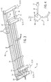
articles 108 and/ormovers 16 to facilitate process management operations (e.g., smart warehousing). In some embodiments, this includes incorporating respective tags and sensors into the track, movers, and articles. In accordance with present embodiments, this may be done in specific ways to facilitate operation. For example,FIG. 7 illustrates an overhead, schematic view of a moving magnet system in accordance with present embodiments. Amover 16 is illustrated traversing atrack 18, which includes a plurality ofcoils 402. Themover 16 includes abody 14 that spans the width of thetrack 18 and engages it onopposite sides wheel sets feedback board 34 represented as residing under thecoils 402 may operate to detect and facilitate control of positional characteristics of themover 16 relative to thetrack 18. To supplement this, asensor 412 is integrated into thetrack 18 and positioned to detect atag 414 integrated with or attached to themover 16. Specifically, thetag 414 and thesensor 412 are positioned such that when themover 16 traverses thetrack 18, thetag 414 can be read by thesensor 412. In other embodiments, thetag 414 and thesensor 412 may be positioned oppositely. That is, thetag 414 may be integrated with or attached to thetrack 18 and thesensor 412 may be coupled with themover 16. For systems wherein it is preferable to provide power to thesensor 412 via thetrack 18, the illustrated embodiment may be utilized. - In yet other embodiments, it may be useful to include a reader on the
mover 16 to facilitate identification ofarticles 108 being transported, as illustrated inFIG. 8 . Specifically,FIG. 8 illustrates amover 16 incorporating a sensor 412 (e.g., a barcode reader or RFID reader) that is configured to read atag 414 disposed on anarticle 108 that is being transported by themover 16. In the illustrated embodiment, themover 16 includes acarriage body 14 that is configured to physically engage atrack 18 with twowheel sets central body 502 and anextension 504 from anarm 506 of thebody 14. It should be noted that the illustratedmover 16 is configured for operation in a moving magnet system, as is clear from the inclusion of amagnet array 508. However, other embodiments may be configured for moving coil operation. Thesensor 412 may include integral electronics 510 (e.g., a power source, communication device) that facilitate operation. For example, theelectronics 510 may include a battery and communication features that facilitates wireless communication with thesupervisory system 110. Also, in the embodiment illustrated byFIG. 8 , themover 16 includestags 414 that facilitate identification of themover 16 byother system sensors 152 that are disposed off of themover 16. - While only certain features of present embodiments have been illustrated and described herein, many modifications and changes will occur to those skilled in the art. It is, therefore, to be understood that the appended claims are intended to cover all such modifications and changes as fall within the disclosure.
Claims (14)
- A linear drive transport system (10), comprising:a plurality of fixed tracks (18);a junction track (20) disposed on a conveyor (28) configured to align the junction track with each of the plurality of fixed tracks, wherein the plurality of fixed tracks and the junction track comprise one of electromagnetic coils (402) or permanent magnets arranged in series along the respective plurality of fixed tracks and the junction track, and wherein the conveyor comprises a horizontal linear drive (114); anda plurality of movers (16) configured to move along the fixed tracks and configured to transition between each of the plurality of fixed tracks and the junction track when aligned, wherein the movers comprise the other of the electromagnetic coils or the permanent magnets,wherein the junction track is configured to receive a mover of the plurality of movers from a first fixed track of the plurality of fixed tracks and to impel the mover onto a second fixed track of the plurality of fixed tracks after being repositioned into alignment with the second fixed track by the conveyor,characterized in that the plurality of fixed tracks (18, 102) is arranged in a first plane of operation, wherein the linear drive transport system further comprises a dual-axis shuttle system (106) including the conveyor and a vertical linear drive (112) configured to move the junction track along a vertical path, wherein the dual-axis shuttle system is configured to align the junction track with at least one additional fixed track arranged in a second plane of operation.
- The system of claim 1, wherein the conveyor (28) comprises a moving magnet linear drive and the junction track (20) is disposed on a shuttle mover (26) of the moving magnet linear drive.
- The system of claim 1, wherein the conveyor (28) comprises a moving coil linear drive and the junction track (20) is disposed on a shuttle mover (26) of the moving coil linear drive.
- The system of claim 1, comprising an additional junction track (20) disposed on an additional conveyor (28) configured to align the additional junction track with one or more of the plurality of fixed tracks (18), the junction track disposed on the conveyor, or both.
- The system of claim 1, comprising the junction track (20) and the conveyor (28) positioned between the plurality of fixed tracks (18, 70) and one or more additional fixed tracks (18, 74), wherein the conveyor is configured to align the junction track with the one or more additional fixed tracks to facilitate transition of a one of the plurality of movers (16) between the junction track and the one or more additional fixed tracks.
- The system of claim 1, comprising a plurality of junction tracks (20) disposed on the conveyor (28), wherein the conveyor is configured to align the plurality of junction tracks with the plurality of fixed tracks (18) in combinations or individually.
- The system of claim 1, comprising position feedback boards (34) integrated with the plurality of fixed tracks (18), wherein the position feedback board is configured to communicate information related to positioning of the plurality of movers (16) to a supervisory controller (110).
- The system of claim 1, comprising tag detectors (38) positioned along each of the plurality of fixed tracks (18), the tag detectors configured to communicate with a supervisory controller (110) and configured to detect tags (36) associated with each of the plurality of movers (16), tags associated with articles being handled by each of the plurality of movers, or both.
- The system of claim 1, wherein the plurality of fixed tracks (18, 70) are positioned in an aligned orientation between the junction track (20) disposed on the conveyor (28) and an additional junction track (20) disposed on an additional conveyor (28) such that the plurality of movers (16) can be transitioned between any of the plurality of fixed tracks by the junction track for traversal to the additional junction track and then transitioned for return along a different one of the plurality of fixed tracks.
- The system of claim 1, wherein the plurality of movers (16) comprise carriages that are configured to couple about the fixed tracks (18) and junction track (20) and wherein the carriages each comprise a body (14) with a first set of rollers (408) on a trunk portion (502) of the body and a second set of rollers (410) positioned opposite the first set of rollers on a tab (504) extending from an arm (506) of the body that is sized to span a side of a track segment of the plurality of fixed tracks such that the first and second set of rollers are configured to engage opposite sides of the track segment.
- The system of claim 1, comprising a tag detector (38) disposed on at least a subset of the plurality of movers (16) and configured to communicate with a supervisory controller (110) configured to monitor locations of articles (108) transported by the system, wherein the tag detector is configured to read a tag (36) on an article engaged for transportation via an associated mover.
- A dual-axis shuttle system (106) for a linear drive transport system (10) according to claim 1, comprising:a conveyor (28) configured to move along a path (50) that is transverse to a plurality of linear drive tracks (18) that are arranged in a first plane of operation and are configured to transport a linear drive mover (16) in one of a moving magnet configuration or a moving coil configuration, wherein the conveyor comprises a horizontal linear drive; anda junction track (20) disposed on the conveyor, wherein the junction track is configured to transport the linear drive mover in the same one of the moving magnet configuration or the moving coil configuration as the plurality of linear drive tracks and wherein the conveyor is configured to align the junction track with at least a subset of the plurality of linear drive tracks to facilitate transfer of the linear drive mover there between,wherein the junction track is configured to receive the linear drive mover from a first linear drive track of the plurality of linear drive tracks and to impel the mover onto a second linear drive track of the plurality of linear drive tracks after being repositioned into alignment with the second linear drive track by the conveyor,wherein the dual-axis shuttle system further comprises a vertical linear drive configured to move the junction track along a vertical path, wherein the dual-axis shuttle system is configured to align the junction track with at least one additional linear drive track arranged in a second plane of operation.
- A method of positioning movers (16) in a linear drive transport system (10) according to claim 1, comprising:aligning a junction track (20) with a first fixed track (18) of a plurality of fixed tracks by moving the junction track with a conveyor (28) on which the junction track is disposed by employing electromagnetic propulsion; andimpelling at least one mover along the first fixed track, transitioning the at least one mover from the first fixed track to the junction track, aligning the junction track with a second fixed track of the plurality of fixed tracks using the conveyor, and transitioning the at least one mover to the second fixed track under the influence of electromagnetic force resulting from interaction between at least one electromagnet coil (402) and at least one permanent magnet (508).
- The method of claim 13, wherein moving the junction track (20) with the conveyor (28) comprises moving a linear drive shuttle mover (26) of the conveyor on which the junction track is disposed along a linear drive track of the conveyor, wherein the linear drive shuttle mover and the linear drive track of the conveyor are in one of a moving magnet or moving coil configuration.
Applications Claiming Priority (1)
| Application Number | Priority Date | Filing Date | Title |
|---|---|---|---|
| US14/563,687 US9611107B2 (en) | 2014-12-08 | 2014-12-08 | Linear drive transport system and method |
Publications (3)
| Publication Number | Publication Date |
|---|---|
| EP3031756A1 EP3031756A1 (en) | 2016-06-15 |
| EP3031756B1 EP3031756B1 (en) | 2017-09-13 |
| EP3031756B2 true EP3031756B2 (en) | 2021-01-06 |
Family
ID=54783440
Family Applications (1)
| Application Number | Title | Priority Date | Filing Date |
|---|---|---|---|
| EP15197911.9A Active EP3031756B2 (en) | 2014-12-08 | 2015-12-04 | Linear drive transport system and method |
Country Status (2)
| Country | Link |
|---|---|
| US (5) | US9611107B2 (en) |
| EP (1) | EP3031756B2 (en) |
Families Citing this family (52)
| Publication number | Priority date | Publication date | Assignee | Title |
|---|---|---|---|---|
| US9611107B2 (en) | 2014-12-08 | 2017-04-04 | Rockwell Automation Technologies, Inc. | Linear drive transport system and method |
| CN105057219B (en) | 2015-07-22 | 2018-11-27 | 杭州亚美利嘉科技有限公司 | Wrap up go-no-go system and method |
| CA2943138A1 (en) * | 2015-09-25 | 2017-03-25 | Multi-Pack Solutions, LLC | Packaging machine with independently controllable movers |
| US11220081B2 (en) * | 2016-05-16 | 2022-01-11 | Cmd Corporation | Method and apparatus for pouch or bag making |
| EP3488245B1 (en) * | 2016-07-21 | 2022-10-12 | Siemens Healthcare Diagnostics Inc. | Linear motor housing construction |
| EP3510457A1 (en) | 2016-09-09 | 2019-07-17 | The Procter and Gamble Company | Methods for simultaneously producing different products on a single production line |
| JP6898436B2 (en) | 2016-09-09 | 2021-07-07 | ザ プロクター アンド ギャンブル カンパニーThe Procter & Gamble Company | Systems and methods for simultaneously filling containers with different fluid compositions |
| CN109690605B (en) | 2016-09-09 | 2022-04-26 | 宝洁公司 | System and method for producing customized products mixed with mass-produced products |
| CN109661624B (en) | 2016-09-09 | 2022-10-25 | 宝洁公司 | System and method for independently guiding carriers of loaded containers to create different finished products |
| EP3509953A1 (en) | 2016-09-09 | 2019-07-17 | The Procter and Gamble Company | System and method for simultaneously filling containers of different shapes and/or sizes |
| CN109661366B (en) | 2016-09-09 | 2022-01-14 | 宝洁公司 | System and method for independently guiding a carrier and delivering containers and closures to a unit operation station |
| EP3510458A2 (en) | 2016-09-09 | 2019-07-17 | The Procter and Gamble Company | System and method for producing products based upon demand |
| EP3509795B1 (en) | 2016-09-09 | 2020-07-29 | The Procter and Gamble Company | Vacuum holder with extensible skirt gasket |
| ES3040606T3 (en) | 2016-10-05 | 2025-11-03 | Laitram Llc | Linear-motor conveyor system |
| WO2018119665A1 (en) * | 2016-12-27 | 2018-07-05 | Abb Schweiz Ag | Conveying system |
| CN108539949B (en) * | 2017-03-01 | 2020-07-31 | 台达电子工业股份有限公司 | Moving magnetic type transfer platform |
| EP3619149B1 (en) | 2017-05-02 | 2025-07-09 | Laitram, L.L.C. | Tray conveyor driven by brushless dc motor |
| CN107160397B (en) | 2017-06-09 | 2023-07-18 | 浙江立镖机器人有限公司 | Modular landmarks for robot walking, landmarks and their robots |
| EP3642142A4 (en) | 2017-06-19 | 2021-03-17 | Laitram, L.L.C. | Monorail tray conveyor |
| US10483895B2 (en) * | 2017-08-25 | 2019-11-19 | Rockwell Automation Technologies, Inc. | Method and apparatus for wireless power transfer to an independent moving cart |
| US20190061558A1 (en) * | 2017-08-31 | 2019-02-28 | Rockwell Automation Technologies, Inc. | Systems and methods for sensing parameters on movers in linear motor systems |
| US10835833B2 (en) * | 2017-09-06 | 2020-11-17 | Universal City Studios Llc | System and method for track ride vehicle orientation |
| KR20200042481A (en) | 2017-09-13 | 2020-04-23 | 라이트람, 엘엘씨 | Monoray tray conveyor with manual guide rail |
| US11165372B2 (en) * | 2017-09-13 | 2021-11-02 | Rockwell Automation Technologies, Inc. | Method and apparatus to characterize loads in a linear synchronous motor system |
| US10965201B2 (en) | 2017-09-25 | 2021-03-30 | Canon Kabushiki Kaisha | Transport system, processing system and manufacturing method of article |
| US10608469B2 (en) | 2017-09-28 | 2020-03-31 | Rockwell Automation Technologies, Inc. | Method and apparatus for power transfer to an independent moving cart during travel along a track |
| US11539244B2 (en) | 2017-09-28 | 2022-12-27 | Rockwell Automation Technologies, Inc. | Method and apparatus for data transmission over an inductive link for an independent cart system |
| FR3074487B1 (en) * | 2017-12-06 | 2022-07-08 | C E R M E X Constructions Etudes Et Rech De Materiels Pour Lemballage Dexpedition | REALIZATION OF BATCHES OF PRODUCTS FOR PALLETIZATION BY LAYERS |
| DE102017223078A1 (en) * | 2017-12-18 | 2019-06-19 | Krones Ag | Apparatus for treating containers |
| EP3501878B1 (en) | 2017-12-22 | 2022-07-13 | B&R Industrial Automation GmbH | Transport device in the form of a linear motor with guideway stator |
| US10807803B2 (en) | 2018-01-31 | 2020-10-20 | Laitram, L.L.C. | Hygienic low-friction magnetic tray and conveyor |
| US10654660B2 (en) | 2018-01-31 | 2020-05-19 | Laitram, L.L.C. | Hygienic magnetic tray and conveyor |
| WO2019199622A1 (en) | 2018-04-10 | 2019-10-17 | The Procter & Gamble Company | Method and apparatus for flexibly assembling packages of absorbent articles |
| AU2019336614B2 (en) | 2018-09-06 | 2023-11-09 | Tompkins Robotics, Inc. | Parcel and article sorting system and method with destination container removal |
| US11004584B2 (en) * | 2018-10-17 | 2021-05-11 | Kang Yao | Electric track system for various appliances via magnetic positioning |
| US12187550B2 (en) * | 2019-04-23 | 2025-01-07 | Yamaha Hatsudoki Kabushiki Kaisha | Linear conveyor system, a control method for a linear conveyor system, a control program for a linear conveyor system and a recording medium |
| DE112019007252T5 (en) | 2019-04-23 | 2021-12-30 | Yamaha Hatsudoki Kabushiki Kaisha | Linear conveyor system, a control method for a linear conveyor system, a control program for a linear conveyor system, and a recording medium |
| CN112240769B (en) * | 2019-07-17 | 2024-04-16 | 北京京东乾石科技有限公司 | Positioning method, system, device and storage medium thereof |
| CN110683302B (en) * | 2019-11-03 | 2024-10-22 | 黑龙江八一农垦大学 | Intelligent rail-mounted rice seedling transportation system |
| IT201900020304A1 (en) * | 2019-11-04 | 2021-05-04 | System Ceramics S P A | Handling device for roller boxes |
| CN114789897A (en) * | 2021-01-25 | 2022-07-26 | 南京以太通信技术有限公司 | Automatic production equipment of assembly line distribution mechanism and packing box |
| DE102021120291A1 (en) * | 2021-08-04 | 2023-02-09 | Md Elektronik Gmbh | Modular switching device for the temporary storage of workpiece carriers for a linear transport system |
| US11767180B1 (en) * | 2021-11-22 | 2023-09-26 | Amazon Technologies, Inc. | Systems and methods to perform perpendicular changes in container shuttle direction |
| CN118679114A (en) | 2022-02-25 | 2024-09-20 | 雅马哈发动机株式会社 | Branching conveyor, conveyor table conveying system, and conveyor table conveying method |
| IT202200008555A1 (en) * | 2022-05-02 | 2023-11-02 | Azionaria Costruzioni Acma Spa | CONVEYOR UNIT OF A CREW TRANSPORTING A PRODUCT |
| US11945665B1 (en) * | 2022-08-03 | 2024-04-02 | Amazon Technologies, Inc. | Automated lateral transfer and elevation of sortation shuttles |
| JP7673102B2 (en) * | 2023-01-12 | 2025-05-08 | 日本金銭機械株式会社 | Transport System |
| DE102023110521A1 (en) * | 2023-04-25 | 2024-10-31 | Beckhoff Automation Gmbh | Linear transport system |
| US12121936B1 (en) | 2023-05-31 | 2024-10-22 | General Mills, Inc. | Processing system for handling pieces of product |
| CN119059282A (en) * | 2023-06-02 | 2024-12-03 | B和R工业自动化有限公司 | Electromagnetic transport system |
| US12545532B2 (en) * | 2023-10-23 | 2026-02-10 | Rockwell Automation Technologies, Inc. | Persistent vehicle identification for an independent cart system |
| US12391495B2 (en) | 2023-10-23 | 2025-08-19 | Rockwell Automation Technologies, Inc. | Magnet arrays for vehicle identification in an independent cart system |
Citations (4)
| Publication number | Priority date | Publication date | Assignee | Title |
|---|---|---|---|---|
| US4849664A (en) † | 1985-08-14 | 1989-07-18 | Fujitsu Limited | Linear motor car system |
| JP2004015894A (en) † | 2002-06-05 | 2004-01-15 | Yaskawa Electric Corp | Linear motor |
| DE102007059611A1 (en) † | 2007-12-11 | 2009-06-18 | Gerhard Schubert Gmbh | Method and device for transporting objects |
| WO2015162182A1 (en) † | 2014-04-25 | 2015-10-29 | Weber Maschinenbau Gmbh Breidenbach | Autonomously electromagnetic transport carrier of food portions |
Family Cites Families (27)
| Publication number | Priority date | Publication date | Assignee | Title |
|---|---|---|---|---|
| DE2830255C2 (en) * | 1978-07-10 | 1985-01-03 | Mannesmann AG, 4000 Düsseldorf | Conveyor track with a conveyor train moving in a pipe |
| GB2133757B (en) | 1983-01-14 | 1987-01-14 | Western Electric Co | A frictionless transport system |
| JPS62166708A (en) | 1986-01-18 | 1987-07-23 | Daifuku Co Ltd | Conveyor using magnetic levitation type linear motor |
| US5156093A (en) * | 1986-12-19 | 1992-10-20 | Kabushiki Kaisha Toshiba | Transportation system of floated-carrier type |
| AT398923B (en) | 1989-04-04 | 1995-02-27 | Sticht Walter | MANUFACTURING SYSTEM WITH PARALLEL AND ADDITIONAL CONVEYOR |
| US6784572B1 (en) | 1991-03-17 | 2004-08-31 | Anorad Corporation | Path arrangement for a multi-track linear motor system and method to control same |
| US5947361A (en) * | 1996-07-25 | 1999-09-07 | Emo Elektromotorenwerk Kamenz Gmbh | Apparatus for transporting fabrics and web-shaped material with an electric drive device |
| JPH11222122A (en) | 1998-02-03 | 1999-08-17 | Shinko Electric Co Ltd | Transfer equipment with branch tracks |
| AU1922300A (en) | 1998-12-04 | 2000-06-26 | Thomson Industries Inc. | Method and apparatus for transferring a carriage assembly between rails |
| US6643917B1 (en) | 2000-01-19 | 2003-11-11 | Delaware Capital Formation | Redundant system for assembly of electronic components to substrates |
| US20020062553A1 (en) | 2000-11-24 | 2002-05-30 | Mirae Corporation | Surface mounting device and method thereof |
| WO2003105324A1 (en) | 2002-06-05 | 2003-12-18 | Jacobs Automation Llc | Controlled motion system |
| US7478749B2 (en) | 2004-05-17 | 2009-01-20 | Thermal Solutions, Inc. | Food preparation system |
| DE502005003332D1 (en) | 2005-06-23 | 2008-04-30 | Bosch Rexroth Mechatronics | Linear motion device with RFID tag |
| DE102008007768B4 (en) | 2008-02-06 | 2020-10-08 | Rovema Gmbh | Device for moving piece goods |
| DE202008016678U1 (en) * | 2008-12-17 | 2009-03-12 | Rofa Rosenheimer Förderanlagen GmbH | Switch for an electric pallet railway |
| US8967051B2 (en) * | 2009-01-23 | 2015-03-03 | Magnemotion, Inc. | Transport system powered by short block linear synchronous motors and switching mechanism |
| KR101748447B1 (en) | 2009-01-23 | 2017-06-16 | 마그네모션, 인코포레이티드 | Improved transport system powered by short block linear synchronous motors and switching mechanism |
| US8616134B2 (en) * | 2009-01-23 | 2013-12-31 | Magnemotion, Inc. | Transport system powered by short block linear synchronous motors |
| DE102009058125B4 (en) | 2009-12-12 | 2013-05-16 | Bernhard Stock | Transport device for distribution of various general cargo and method for operating a transport device |
| KR101487803B1 (en) * | 2010-07-09 | 2015-01-29 | 가부시키가이샤 다이후쿠 | Trolley-type conveyance device |
| DE102011003682A1 (en) | 2011-02-07 | 2012-08-09 | Robert Bosch Gmbh | Transport device with recognition function |
| JP5912426B2 (en) | 2011-11-07 | 2016-04-27 | ヤマハ発動機株式会社 | Linear conveyor |
| US8896241B2 (en) | 2011-11-16 | 2014-11-25 | Rockwell Automation Technologies, Inc. | Controlled motion system |
| JP6199378B2 (en) * | 2012-05-22 | 2017-09-20 | シーメンス・ヘルスケア・ダイアグノスティックス・インコーポレーテッドSiemens Healthcare Diagnostics Inc. | Linear random access queue |
| US10243441B2 (en) * | 2013-03-15 | 2019-03-26 | Rockwell Automation, Inc. | Controlled motion system having a magnetic flux bridge joining linear motor sections |
| US9611107B2 (en) | 2014-12-08 | 2017-04-04 | Rockwell Automation Technologies, Inc. | Linear drive transport system and method |
-
2014
- 2014-12-08 US US14/563,687 patent/US9611107B2/en active Active
-
2015
- 2015-12-04 EP EP15197911.9A patent/EP3031756B2/en active Active
-
2017
- 2017-03-10 US US15/456,231 patent/US9957119B2/en active Active
-
2018
- 2018-04-24 US US15/961,565 patent/US10280016B2/en active Active
-
2019
- 2019-05-06 US US16/404,186 patent/US10577196B2/en active Active
-
2020
- 2020-02-12 US US16/789,043 patent/US10829317B2/en active Active
Patent Citations (4)
| Publication number | Priority date | Publication date | Assignee | Title |
|---|---|---|---|---|
| US4849664A (en) † | 1985-08-14 | 1989-07-18 | Fujitsu Limited | Linear motor car system |
| JP2004015894A (en) † | 2002-06-05 | 2004-01-15 | Yaskawa Electric Corp | Linear motor |
| DE102007059611A1 (en) † | 2007-12-11 | 2009-06-18 | Gerhard Schubert Gmbh | Method and device for transporting objects |
| WO2015162182A1 (en) † | 2014-04-25 | 2015-10-29 | Weber Maschinenbau Gmbh Breidenbach | Autonomously electromagnetic transport carrier of food portions |
Also Published As
| Publication number | Publication date |
|---|---|
| US10280016B2 (en) | 2019-05-07 |
| US20190256303A1 (en) | 2019-08-22 |
| US9611107B2 (en) | 2017-04-04 |
| US10829317B2 (en) | 2020-11-10 |
| EP3031756A1 (en) | 2016-06-15 |
| US20180237232A1 (en) | 2018-08-23 |
| US10577196B2 (en) | 2020-03-03 |
| US20200180877A1 (en) | 2020-06-11 |
| EP3031756B1 (en) | 2017-09-13 |
| US20170183170A1 (en) | 2017-06-29 |
| US9957119B2 (en) | 2018-05-01 |
| US20160159585A1 (en) | 2016-06-09 |
Similar Documents
| Publication | Publication Date | Title |
|---|---|---|
| US10829317B2 (en) | Linear drive transport system and method | |
| CN108701637B (en) | Operating systems with independent coordinated shuttles for industrial automation | |
| TWI555689B (en) | Linear conveyor | |
| EP2691319B1 (en) | Pallet-based position adjustment system | |
| EP2403784B1 (en) | Multi-mode scroll cam conveyor system | |
| US8109443B2 (en) | Precise transport positioning apparatus using a closed loop controlled, non-direct drive or friction drive system with absolute positioning encoder | |
| EP2633946B1 (en) | Conveyance system | |
| CN113291734A (en) | Linear motor conveyor system | |
| CN103931091A (en) | Linear conveyor, conveyance carriage, and drive control method for linear conveyor | |
| US10625948B2 (en) | Conveyance apparatus, conveyance system, and method of controlling conveyance system | |
| US12479097B2 (en) | Coordinated motion of a robot and vehicle in an independent cart system | |
| US12391495B2 (en) | Magnet arrays for vehicle identification in an independent cart system | |
| US12459118B2 (en) | Method of coordinating motion of a robot and vehicle in an independent cart system | |
| JP7051348B2 (en) | Transport system and processing system | |
| JP7379130B2 (en) | Conveyance device | |
| US11964685B2 (en) | System and method for control of carts at a station for an independent cart system | |
| CN219839186U (en) | Multichannel conveying device | |
| JPH01204111A (en) | Carrier vehicle |
Legal Events
| Date | Code | Title | Description |
|---|---|---|---|
| PUAI | Public reference made under article 153(3) epc to a published international application that has entered the european phase |
Free format text: ORIGINAL CODE: 0009012 |
|
| AK | Designated contracting states |
Kind code of ref document: A1 Designated state(s): AL AT BE BG CH CY CZ DE DK EE ES FI FR GB GR HR HU IE IS IT LI LT LU LV MC MK MT NL NO PL PT RO RS SE SI SK SM TR |
|
| AX | Request for extension of the european patent |
Extension state: BA ME |
|
| STAA | Information on the status of an ep patent application or granted ep patent |
Free format text: STATUS: REQUEST FOR EXAMINATION WAS MADE |
|
| 17P | Request for examination filed |
Effective date: 20161215 |
|
| RBV | Designated contracting states (corrected) |
Designated state(s): AL AT BE BG CH CY CZ DE DK EE ES FI FR GB GR HR HU IE IS IT LI LT LU LV MC MK MT NL NO PL PT RO RS SE SI SK SM TR |
|
| GRAP | Despatch of communication of intention to grant a patent |
Free format text: ORIGINAL CODE: EPIDOSNIGR1 |
|
| STAA | Information on the status of an ep patent application or granted ep patent |
Free format text: STATUS: GRANT OF PATENT IS INTENDED |
|
| INTG | Intention to grant announced |
Effective date: 20170511 |
|
| GRAS | Grant fee paid |
Free format text: ORIGINAL CODE: EPIDOSNIGR3 |
|
| GRAA | (expected) grant |
Free format text: ORIGINAL CODE: 0009210 |
|
| STAA | Information on the status of an ep patent application or granted ep patent |
Free format text: STATUS: THE PATENT HAS BEEN GRANTED |
|
| AK | Designated contracting states |
Kind code of ref document: B1 Designated state(s): AL AT BE BG CH CY CZ DE DK EE ES FI FR GB GR HR HU IE IS IT LI LT LU LV MC MK MT NL NO PL PT RO RS SE SI SK SM TR |
|
| REG | Reference to a national code |
Ref country code: GB Ref legal event code: FG4D |
|
| REG | Reference to a national code |
Ref country code: CH Ref legal event code: EP |
|
| REG | Reference to a national code |
Ref country code: IE Ref legal event code: FG4D |
|
| REG | Reference to a national code |
Ref country code: AT Ref legal event code: REF Ref document number: 927916 Country of ref document: AT Kind code of ref document: T Effective date: 20171015 |
|
| REG | Reference to a national code |
Ref country code: DE Ref legal event code: R096 Ref document number: 602015004736 Country of ref document: DE |
|
| REG | Reference to a national code |
Ref country code: FR Ref legal event code: PLFP Year of fee payment: 3 |
|
| REG | Reference to a national code |
Ref country code: NL Ref legal event code: MP Effective date: 20170913 |
|
| REG | Reference to a national code |
Ref country code: LT Ref legal event code: MG4D |
|
| PG25 | Lapsed in a contracting state [announced via postgrant information from national office to epo] |
Ref country code: SE Free format text: LAPSE BECAUSE OF FAILURE TO SUBMIT A TRANSLATION OF THE DESCRIPTION OR TO PAY THE FEE WITHIN THE PRESCRIBED TIME-LIMIT Effective date: 20170913 Ref country code: NO Free format text: LAPSE BECAUSE OF FAILURE TO SUBMIT A TRANSLATION OF THE DESCRIPTION OR TO PAY THE FEE WITHIN THE PRESCRIBED TIME-LIMIT Effective date: 20171213 Ref country code: HR Free format text: LAPSE BECAUSE OF FAILURE TO SUBMIT A TRANSLATION OF THE DESCRIPTION OR TO PAY THE FEE WITHIN THE PRESCRIBED TIME-LIMIT Effective date: 20170913 Ref country code: FI Free format text: LAPSE BECAUSE OF FAILURE TO SUBMIT A TRANSLATION OF THE DESCRIPTION OR TO PAY THE FEE WITHIN THE PRESCRIBED TIME-LIMIT Effective date: 20170913 Ref country code: LT Free format text: LAPSE BECAUSE OF FAILURE TO SUBMIT A TRANSLATION OF THE DESCRIPTION OR TO PAY THE FEE WITHIN THE PRESCRIBED TIME-LIMIT Effective date: 20170913 |
|
| REG | Reference to a national code |
Ref country code: AT Ref legal event code: MK05 Ref document number: 927916 Country of ref document: AT Kind code of ref document: T Effective date: 20170913 |
|
| PG25 | Lapsed in a contracting state [announced via postgrant information from national office to epo] |
Ref country code: ES Free format text: LAPSE BECAUSE OF FAILURE TO SUBMIT A TRANSLATION OF THE DESCRIPTION OR TO PAY THE FEE WITHIN THE PRESCRIBED TIME-LIMIT Effective date: 20170913 Ref country code: RS Free format text: LAPSE BECAUSE OF FAILURE TO SUBMIT A TRANSLATION OF THE DESCRIPTION OR TO PAY THE FEE WITHIN THE PRESCRIBED TIME-LIMIT Effective date: 20170913 Ref country code: LV Free format text: LAPSE BECAUSE OF FAILURE TO SUBMIT A TRANSLATION OF THE DESCRIPTION OR TO PAY THE FEE WITHIN THE PRESCRIBED TIME-LIMIT Effective date: 20170913 Ref country code: GR Free format text: LAPSE BECAUSE OF FAILURE TO SUBMIT A TRANSLATION OF THE DESCRIPTION OR TO PAY THE FEE WITHIN THE PRESCRIBED TIME-LIMIT Effective date: 20171214 Ref country code: BG Free format text: LAPSE BECAUSE OF FAILURE TO SUBMIT A TRANSLATION OF THE DESCRIPTION OR TO PAY THE FEE WITHIN THE PRESCRIBED TIME-LIMIT Effective date: 20171213 |
|
| PG25 | Lapsed in a contracting state [announced via postgrant information from national office to epo] |
Ref country code: NL Free format text: LAPSE BECAUSE OF FAILURE TO SUBMIT A TRANSLATION OF THE DESCRIPTION OR TO PAY THE FEE WITHIN THE PRESCRIBED TIME-LIMIT Effective date: 20170913 |
|
| PG25 | Lapsed in a contracting state [announced via postgrant information from national office to epo] |
Ref country code: PL Free format text: LAPSE BECAUSE OF FAILURE TO SUBMIT A TRANSLATION OF THE DESCRIPTION OR TO PAY THE FEE WITHIN THE PRESCRIBED TIME-LIMIT Effective date: 20170913 Ref country code: CZ Free format text: LAPSE BECAUSE OF FAILURE TO SUBMIT A TRANSLATION OF THE DESCRIPTION OR TO PAY THE FEE WITHIN THE PRESCRIBED TIME-LIMIT Effective date: 20170913 Ref country code: RO Free format text: LAPSE BECAUSE OF FAILURE TO SUBMIT A TRANSLATION OF THE DESCRIPTION OR TO PAY THE FEE WITHIN THE PRESCRIBED TIME-LIMIT Effective date: 20170913 |
|
| PG25 | Lapsed in a contracting state [announced via postgrant information from national office to epo] |
Ref country code: SM Free format text: LAPSE BECAUSE OF FAILURE TO SUBMIT A TRANSLATION OF THE DESCRIPTION OR TO PAY THE FEE WITHIN THE PRESCRIBED TIME-LIMIT Effective date: 20170913 Ref country code: SK Free format text: LAPSE BECAUSE OF FAILURE TO SUBMIT A TRANSLATION OF THE DESCRIPTION OR TO PAY THE FEE WITHIN THE PRESCRIBED TIME-LIMIT Effective date: 20170913 Ref country code: IS Free format text: LAPSE BECAUSE OF FAILURE TO SUBMIT A TRANSLATION OF THE DESCRIPTION OR TO PAY THE FEE WITHIN THE PRESCRIBED TIME-LIMIT Effective date: 20180113 Ref country code: IT Free format text: LAPSE BECAUSE OF FAILURE TO SUBMIT A TRANSLATION OF THE DESCRIPTION OR TO PAY THE FEE WITHIN THE PRESCRIBED TIME-LIMIT Effective date: 20170913 Ref country code: AT Free format text: LAPSE BECAUSE OF FAILURE TO SUBMIT A TRANSLATION OF THE DESCRIPTION OR TO PAY THE FEE WITHIN THE PRESCRIBED TIME-LIMIT Effective date: 20170913 Ref country code: EE Free format text: LAPSE BECAUSE OF FAILURE TO SUBMIT A TRANSLATION OF THE DESCRIPTION OR TO PAY THE FEE WITHIN THE PRESCRIBED TIME-LIMIT Effective date: 20170913 |
|
| REG | Reference to a national code |
Ref country code: DE Ref legal event code: R026 Ref document number: 602015004736 Country of ref document: DE |
|
| PLBI | Opposition filed |
Free format text: ORIGINAL CODE: 0009260 |
|
| PLAX | Notice of opposition and request to file observation + time limit sent |
Free format text: ORIGINAL CODE: EPIDOSNOBS2 |
|
| 26 | Opposition filed |
Opponent name: KRONES AG Effective date: 20180613 |
|
| PG25 | Lapsed in a contracting state [announced via postgrant information from national office to epo] |
Ref country code: DK Free format text: LAPSE BECAUSE OF FAILURE TO SUBMIT A TRANSLATION OF THE DESCRIPTION OR TO PAY THE FEE WITHIN THE PRESCRIBED TIME-LIMIT Effective date: 20170913 |
|
| REG | Reference to a national code |
Ref country code: IE Ref legal event code: MM4A |
|
| PG25 | Lapsed in a contracting state [announced via postgrant information from national office to epo] |
Ref country code: LU Free format text: LAPSE BECAUSE OF NON-PAYMENT OF DUE FEES Effective date: 20171204 Ref country code: MT Free format text: LAPSE BECAUSE OF NON-PAYMENT OF DUE FEES Effective date: 20171204 |
|
| REG | Reference to a national code |
Ref country code: BE Ref legal event code: MM Effective date: 20171231 |
|
| PG25 | Lapsed in a contracting state [announced via postgrant information from national office to epo] |
Ref country code: IE Free format text: LAPSE BECAUSE OF NON-PAYMENT OF DUE FEES Effective date: 20171204 |
|
| PLAF | Information modified related to communication of a notice of opposition and request to file observations + time limit |
Free format text: ORIGINAL CODE: EPIDOSCOBS2 |
|
| PG25 | Lapsed in a contracting state [announced via postgrant information from national office to epo] |
Ref country code: BE Free format text: LAPSE BECAUSE OF NON-PAYMENT OF DUE FEES Effective date: 20171231 Ref country code: SI Free format text: LAPSE BECAUSE OF FAILURE TO SUBMIT A TRANSLATION OF THE DESCRIPTION OR TO PAY THE FEE WITHIN THE PRESCRIBED TIME-LIMIT Effective date: 20170913 |
|
| PLBP | Opposition withdrawn |
Free format text: ORIGINAL CODE: 0009264 |
|
| PG25 | Lapsed in a contracting state [announced via postgrant information from national office to epo] |
Ref country code: MC Free format text: LAPSE BECAUSE OF FAILURE TO SUBMIT A TRANSLATION OF THE DESCRIPTION OR TO PAY THE FEE WITHIN THE PRESCRIBED TIME-LIMIT Effective date: 20170913 Ref country code: HU Free format text: LAPSE BECAUSE OF FAILURE TO SUBMIT A TRANSLATION OF THE DESCRIPTION OR TO PAY THE FEE WITHIN THE PRESCRIBED TIME-LIMIT; INVALID AB INITIO Effective date: 20151204 |
|
| REG | Reference to a national code |
Ref country code: CH Ref legal event code: PL |
|
| PG25 | Lapsed in a contracting state [announced via postgrant information from national office to epo] |
Ref country code: CY Free format text: LAPSE BECAUSE OF FAILURE TO SUBMIT A TRANSLATION OF THE DESCRIPTION OR TO PAY THE FEE WITHIN THE PRESCRIBED TIME-LIMIT Effective date: 20170913 |
|
| PG25 | Lapsed in a contracting state [announced via postgrant information from national office to epo] |
Ref country code: MK Free format text: LAPSE BECAUSE OF FAILURE TO SUBMIT A TRANSLATION OF THE DESCRIPTION OR TO PAY THE FEE WITHIN THE PRESCRIBED TIME-LIMIT Effective date: 20170913 |
|
| PG25 | Lapsed in a contracting state [announced via postgrant information from national office to epo] |
Ref country code: LI Free format text: LAPSE BECAUSE OF NON-PAYMENT OF DUE FEES Effective date: 20181231 Ref country code: CH Free format text: LAPSE BECAUSE OF NON-PAYMENT OF DUE FEES Effective date: 20181231 |
|
| PG25 | Lapsed in a contracting state [announced via postgrant information from national office to epo] |
Ref country code: TR Free format text: LAPSE BECAUSE OF FAILURE TO SUBMIT A TRANSLATION OF THE DESCRIPTION OR TO PAY THE FEE WITHIN THE PRESCRIBED TIME-LIMIT Effective date: 20170913 |
|
| PG25 | Lapsed in a contracting state [announced via postgrant information from national office to epo] |
Ref country code: PT Free format text: LAPSE BECAUSE OF FAILURE TO SUBMIT A TRANSLATION OF THE DESCRIPTION OR TO PAY THE FEE WITHIN THE PRESCRIBED TIME-LIMIT Effective date: 20170913 |
|
| PG25 | Lapsed in a contracting state [announced via postgrant information from national office to epo] |
Ref country code: AL Free format text: LAPSE BECAUSE OF FAILURE TO SUBMIT A TRANSLATION OF THE DESCRIPTION OR TO PAY THE FEE WITHIN THE PRESCRIBED TIME-LIMIT Effective date: 20170913 |
|
| PUAH | Patent maintained in amended form |
Free format text: ORIGINAL CODE: 0009272 |
|
| STAA | Information on the status of an ep patent application or granted ep patent |
Free format text: STATUS: PATENT MAINTAINED AS AMENDED |
|
| 27A | Patent maintained in amended form |
Effective date: 20210106 |
|
| AK | Designated contracting states |
Kind code of ref document: B2 Designated state(s): AL AT BE BG CH CY CZ DE DK EE ES FI FR GB GR HR HU IE IS IT LI LT LU LV MC MK MT NL NO PL PT RO RS SE SI SK SM TR |
|
| REG | Reference to a national code |
Ref country code: DE Ref legal event code: R102 Ref document number: 602015004736 Country of ref document: DE |
|
| P01 | Opt-out of the competence of the unified patent court (upc) registered |
Effective date: 20230404 |
|
| PGFP | Annual fee paid to national office [announced via postgrant information from national office to epo] |
Ref country code: DE Payment date: 20251126 Year of fee payment: 11 |
|
| PGFP | Annual fee paid to national office [announced via postgrant information from national office to epo] |
Ref country code: GB Payment date: 20251119 Year of fee payment: 11 |
|
| PGFP | Annual fee paid to national office [announced via postgrant information from national office to epo] |
Ref country code: FR Payment date: 20251120 Year of fee payment: 11 |