EP3031530A2 - Einrichtung zum steuern von düsen - Google Patents
Einrichtung zum steuern von düsen Download PDFInfo
- Publication number
- EP3031530A2 EP3031530A2 EP15192302.6A EP15192302A EP3031530A2 EP 3031530 A2 EP3031530 A2 EP 3031530A2 EP 15192302 A EP15192302 A EP 15192302A EP 3031530 A2 EP3031530 A2 EP 3031530A2
- Authority
- EP
- European Patent Office
- Prior art keywords
- nozzle
- fluid
- shape memory
- memory element
- fluid channel
- Prior art date
- Legal status (The legal status is an assumption and is not a legal conclusion. Google has not performed a legal analysis and makes no representation as to the accuracy of the status listed.)
- Granted
Links
Images



Classifications
-
- B—PERFORMING OPERATIONS; TRANSPORTING
- B05—SPRAYING OR ATOMISING IN GENERAL; APPLYING FLUENT MATERIALS TO SURFACES, IN GENERAL
- B05B—SPRAYING APPARATUS; ATOMISING APPARATUS; NOZZLES
- B05B1/00—Nozzles, spray heads or other outlets, with or without auxiliary devices such as valves, heating means
- B05B1/30—Nozzles, spray heads or other outlets, with or without auxiliary devices such as valves, heating means designed to control volume of flow, e.g. with adjustable passages
- B05B1/3026—Gate valves; Sliding valves; Cocks
-
- B—PERFORMING OPERATIONS; TRANSPORTING
- B05—SPRAYING OR ATOMISING IN GENERAL; APPLYING FLUENT MATERIALS TO SURFACES, IN GENERAL
- B05B—SPRAYING APPARATUS; ATOMISING APPARATUS; NOZZLES
- B05B1/00—Nozzles, spray heads or other outlets, with or without auxiliary devices such as valves, heating means
- B05B1/14—Nozzles, spray heads or other outlets, with or without auxiliary devices such as valves, heating means with multiple outlet openings; with strainers in or outside the outlet opening
- B05B1/16—Nozzles, spray heads or other outlets, with or without auxiliary devices such as valves, heating means with multiple outlet openings; with strainers in or outside the outlet opening having selectively- effective outlets
- B05B1/1627—Nozzles, spray heads or other outlets, with or without auxiliary devices such as valves, heating means with multiple outlet openings; with strainers in or outside the outlet opening having selectively- effective outlets with a selecting mechanism comprising a gate valve, a sliding valve or a cock
- B05B1/1636—Nozzles, spray heads or other outlets, with or without auxiliary devices such as valves, heating means with multiple outlet openings; with strainers in or outside the outlet opening having selectively- effective outlets with a selecting mechanism comprising a gate valve, a sliding valve or a cock by relative rotative movement of the valve elements
- B05B1/1645—Nozzles, spray heads or other outlets, with or without auxiliary devices such as valves, heating means with multiple outlet openings; with strainers in or outside the outlet opening having selectively- effective outlets with a selecting mechanism comprising a gate valve, a sliding valve or a cock by relative rotative movement of the valve elements the outlets being rotated during selection
- B05B1/1654—Nozzles, spray heads or other outlets, with or without auxiliary devices such as valves, heating means with multiple outlet openings; with strainers in or outside the outlet opening having selectively- effective outlets with a selecting mechanism comprising a gate valve, a sliding valve or a cock by relative rotative movement of the valve elements the outlets being rotated during selection about an axis parallel to the liquid passage in the stationary valve element
-
- B—PERFORMING OPERATIONS; TRANSPORTING
- B05—SPRAYING OR ATOMISING IN GENERAL; APPLYING FLUENT MATERIALS TO SURFACES, IN GENERAL
- B05B—SPRAYING APPARATUS; ATOMISING APPARATUS; NOZZLES
- B05B1/00—Nozzles, spray heads or other outlets, with or without auxiliary devices such as valves, heating means
- B05B1/14—Nozzles, spray heads or other outlets, with or without auxiliary devices such as valves, heating means with multiple outlet openings; with strainers in or outside the outlet opening
- B05B1/16—Nozzles, spray heads or other outlets, with or without auxiliary devices such as valves, heating means with multiple outlet openings; with strainers in or outside the outlet opening having selectively- effective outlets
- B05B1/1627—Nozzles, spray heads or other outlets, with or without auxiliary devices such as valves, heating means with multiple outlet openings; with strainers in or outside the outlet opening having selectively- effective outlets with a selecting mechanism comprising a gate valve, a sliding valve or a cock
- B05B1/1663—Nozzles, spray heads or other outlets, with or without auxiliary devices such as valves, heating means with multiple outlet openings; with strainers in or outside the outlet opening having selectively- effective outlets with a selecting mechanism comprising a gate valve, a sliding valve or a cock by relative translatory movement of the valve elements
-
- B—PERFORMING OPERATIONS; TRANSPORTING
- B05—SPRAYING OR ATOMISING IN GENERAL; APPLYING FLUENT MATERIALS TO SURFACES, IN GENERAL
- B05B—SPRAYING APPARATUS; ATOMISING APPARATUS; NOZZLES
- B05B1/00—Nozzles, spray heads or other outlets, with or without auxiliary devices such as valves, heating means
- B05B1/14—Nozzles, spray heads or other outlets, with or without auxiliary devices such as valves, heating means with multiple outlet openings; with strainers in or outside the outlet opening
- B05B1/16—Nozzles, spray heads or other outlets, with or without auxiliary devices such as valves, heating means with multiple outlet openings; with strainers in or outside the outlet opening having selectively- effective outlets
- B05B1/169—Nozzles, spray heads or other outlets, with or without auxiliary devices such as valves, heating means with multiple outlet openings; with strainers in or outside the outlet opening having selectively- effective outlets having three or more selectively effective outlets
-
- B—PERFORMING OPERATIONS; TRANSPORTING
- B05—SPRAYING OR ATOMISING IN GENERAL; APPLYING FLUENT MATERIALS TO SURFACES, IN GENERAL
- B05B—SPRAYING APPARATUS; ATOMISING APPARATUS; NOZZLES
- B05B1/00—Nozzles, spray heads or other outlets, with or without auxiliary devices such as valves, heating means
- B05B1/30—Nozzles, spray heads or other outlets, with or without auxiliary devices such as valves, heating means designed to control volume of flow, e.g. with adjustable passages
-
- B—PERFORMING OPERATIONS; TRANSPORTING
- B05—SPRAYING OR ATOMISING IN GENERAL; APPLYING FLUENT MATERIALS TO SURFACES, IN GENERAL
- B05B—SPRAYING APPARATUS; ATOMISING APPARATUS; NOZZLES
- B05B1/00—Nozzles, spray heads or other outlets, with or without auxiliary devices such as valves, heating means
- B05B1/30—Nozzles, spray heads or other outlets, with or without auxiliary devices such as valves, heating means designed to control volume of flow, e.g. with adjustable passages
- B05B1/32—Nozzles, spray heads or other outlets, with or without auxiliary devices such as valves, heating means designed to control volume of flow, e.g. with adjustable passages in which a valve member forms part of the outlet opening
-
- B—PERFORMING OPERATIONS; TRANSPORTING
- B05—SPRAYING OR ATOMISING IN GENERAL; APPLYING FLUENT MATERIALS TO SURFACES, IN GENERAL
- B05B—SPRAYING APPARATUS; ATOMISING APPARATUS; NOZZLES
- B05B12/00—Arrangements for controlling delivery; Arrangements for controlling the spray area
-
- B—PERFORMING OPERATIONS; TRANSPORTING
- B05—SPRAYING OR ATOMISING IN GENERAL; APPLYING FLUENT MATERIALS TO SURFACES, IN GENERAL
- B05B—SPRAYING APPARATUS; ATOMISING APPARATUS; NOZZLES
- B05B15/00—Details of spraying plant or spraying apparatus not otherwise provided for; Accessories
- B05B15/60—Arrangements for mounting, supporting or holding spraying apparatus
- B05B15/65—Mounting arrangements for fluid connection of the spraying apparatus or its outlets to flow conduits
- B05B15/652—Mounting arrangements for fluid connection of the spraying apparatus or its outlets to flow conduits whereby the jet can be oriented
-
- B—PERFORMING OPERATIONS; TRANSPORTING
- B05—SPRAYING OR ATOMISING IN GENERAL; APPLYING FLUENT MATERIALS TO SURFACES, IN GENERAL
- B05B—SPRAYING APPARATUS; ATOMISING APPARATUS; NOZZLES
- B05B15/00—Details of spraying plant or spraying apparatus not otherwise provided for; Accessories
- B05B15/60—Arrangements for mounting, supporting or holding spraying apparatus
- B05B15/65—Mounting arrangements for fluid connection of the spraying apparatus or its outlets to flow conduits
- B05B15/658—Mounting arrangements for fluid connection of the spraying apparatus or its outlets to flow conduits the spraying apparatus or its outlet axis being perpendicular to the flow conduit
-
- B—PERFORMING OPERATIONS; TRANSPORTING
- B05—SPRAYING OR ATOMISING IN GENERAL; APPLYING FLUENT MATERIALS TO SURFACES, IN GENERAL
- B05B—SPRAYING APPARATUS; ATOMISING APPARATUS; NOZZLES
- B05B15/00—Details of spraying plant or spraying apparatus not otherwise provided for; Accessories
- B05B15/60—Arrangements for mounting, supporting or holding spraying apparatus
- B05B15/68—Arrangements for adjusting the position of spray heads
-
- B—PERFORMING OPERATIONS; TRANSPORTING
- B08—CLEANING
- B08B—CLEANING IN GENERAL; PREVENTION OF FOULING IN GENERAL
- B08B9/00—Cleaning hollow articles by methods or apparatus specially adapted thereto
- B08B9/02—Cleaning pipes or tubes or systems of pipes or tubes
- B08B9/027—Cleaning the internal surfaces; Removal of blockages
- B08B9/04—Cleaning the internal surfaces; Removal of blockages using cleaning devices introduced into and moved along the pipes
-
- B—PERFORMING OPERATIONS; TRANSPORTING
- B08—CLEANING
- B08B—CLEANING IN GENERAL; PREVENTION OF FOULING IN GENERAL
- B08B9/00—Cleaning hollow articles by methods or apparatus specially adapted thereto
- B08B9/02—Cleaning pipes or tubes or systems of pipes or tubes
- B08B9/027—Cleaning the internal surfaces; Removal of blockages
- B08B9/04—Cleaning the internal surfaces; Removal of blockages using cleaning devices introduced into and moved along the pipes
- B08B9/043—Cleaning the internal surfaces; Removal of blockages using cleaning devices introduced into and moved along the pipes moved by externally powered mechanical linkage, e.g. pushed or drawn through the pipes
- B08B9/0433—Cleaning the internal surfaces; Removal of blockages using cleaning devices introduced into and moved along the pipes moved by externally powered mechanical linkage, e.g. pushed or drawn through the pipes provided exclusively with fluid jets as cleaning tools
-
- B—PERFORMING OPERATIONS; TRANSPORTING
- B08—CLEANING
- B08B—CLEANING IN GENERAL; PREVENTION OF FOULING IN GENERAL
- B08B9/00—Cleaning hollow articles by methods or apparatus specially adapted thereto
- B08B9/02—Cleaning pipes or tubes or systems of pipes or tubes
- B08B9/027—Cleaning the internal surfaces; Removal of blockages
- B08B9/04—Cleaning the internal surfaces; Removal of blockages using cleaning devices introduced into and moved along the pipes
- B08B9/049—Cleaning the internal surfaces; Removal of blockages using cleaning devices introduced into and moved along the pipes having self-contained propelling means for moving the cleaning devices along the pipes, i.e. self-propelled
- B08B9/0495—Nozzles propelled by fluid jets
-
- E—FIXED CONSTRUCTIONS
- E03—WATER SUPPLY; SEWERAGE
- E03F—SEWERS; CESSPOOLS
- E03F7/00—Other installations or implements for operating sewer systems, e.g. for preventing or indicating stoppage; Emptying cesspools
- E03F7/12—Installations enabling inspection personnel to drive along sewer canals
-
- E—FIXED CONSTRUCTIONS
- E03—WATER SUPPLY; SEWERAGE
- E03F—SEWERS; CESSPOOLS
- E03F9/00—Arrangements or fixed installations methods or devices for cleaning or clearing sewer pipes, e.g. by flushing
-
- F—MECHANICAL ENGINEERING; LIGHTING; HEATING; WEAPONS; BLASTING
- F16—ENGINEERING ELEMENTS AND UNITS; GENERAL MEASURES FOR PRODUCING AND MAINTAINING EFFECTIVE FUNCTIONING OF MACHINES OR INSTALLATIONS; THERMAL INSULATION IN GENERAL
- F16K—VALVES; TAPS; COCKS; ACTUATING-FLOATS; DEVICES FOR VENTING OR AERATING
- F16K31/00—Actuating devices; Operating means; Releasing devices
- F16K31/002—Actuating devices; Operating means; Releasing devices actuated by temperature variation
-
- F—MECHANICAL ENGINEERING; LIGHTING; HEATING; WEAPONS; BLASTING
- F16—ENGINEERING ELEMENTS AND UNITS; GENERAL MEASURES FOR PRODUCING AND MAINTAINING EFFECTIVE FUNCTIONING OF MACHINES OR INSTALLATIONS; THERMAL INSULATION IN GENERAL
- F16K—VALVES; TAPS; COCKS; ACTUATING-FLOATS; DEVICES FOR VENTING OR AERATING
- F16K31/00—Actuating devices; Operating means; Releasing devices
- F16K31/02—Actuating devices; Operating means; Releasing devices electric; magnetic
- F16K31/025—Actuating devices; Operating means; Releasing devices electric; magnetic actuated by thermo-electric means
-
- G—PHYSICS
- G01—MEASURING; TESTING
- G01M—TESTING STATIC OR DYNAMIC BALANCE OF MACHINES OR STRUCTURES; TESTING OF STRUCTURES OR APPARATUS, NOT OTHERWISE PROVIDED FOR
- G01M3/00—Investigating fluid-tightness of structures
- G01M3/005—Investigating fluid-tightness of structures using pigs or moles
-
- G—PHYSICS
- G03—PHOTOGRAPHY; CINEMATOGRAPHY; ANALOGOUS TECHNIQUES USING WAVES OTHER THAN OPTICAL WAVES; ELECTROGRAPHY; HOLOGRAPHY
- G03B—APPARATUS OR ARRANGEMENTS FOR TAKING PHOTOGRAPHS OR FOR PROJECTING OR VIEWING THEM; APPARATUS OR ARRANGEMENTS EMPLOYING ANALOGOUS TECHNIQUES USING WAVES OTHER THAN OPTICAL WAVES; ACCESSORIES THEREFOR
- G03B37/00—Panoramic or wide-screen photography; Photographing extended surfaces, e.g. for surveying; Photographing internal surfaces, e.g. of pipe
- G03B37/005—Photographing internal surfaces, e.g. of pipe
Definitions
- the invention relates to a device for controlling nozzles, in particular a flushing head of an inspection and / or cleaning system, and a flushing head with at least one nozzle and at least one device according to the invention for controlling the nozzle, and an inspection and / or cleaning system with a flushing head according to the invention ,
- sewer inspection and / or maintenance systems or sewer cleaning systems that can be introduced into the sewer pipe and moved in the sewer pipe, such as moved or advanced, can be.
- a rinsing head or a plurality of rinsing heads wherein the rinsing heads can each have one or more nozzles (also called rinsing nozzles).
- the nozzles have a nozzle housing in which a water channel is formed, through which the flushing water supplied to the flushing water flow and can escape with a certain pressure from the water channel.
- the entire rinse head must be moved to alter the angle of the exiting water jet relative to the pipe inner wall or complex mechanical shut-off devices be integrated into the flushing head to block the water outlet from individual nozzles, if the flushing head has multiple nozzles.
- the water outlet from the nozzles can be interrupted, in which the complete water supply to the flushing head is interrupted. However, all nozzles of the flushing head are affected.
- complex mechanical devices or appropriately designed electromechanical devices must be integrated into the flushing head.
- the invention is therefore based on the object to avoid the disadvantages mentioned above at least partially and to provide solutions for controlling at least one nozzle, in particular a flushing head, which still allow a more flexible use of the nozzle or the flushing head in a particularly compact design of the flushing head.
- this object is achieved with a device for controlling at least one nozzle, with a flushing head, which has a nozzle and at least one device according to the invention for controlling the nozzle, as well as with an inspection and / or cleaning system according to the independent patent claims.
- the control means can be provided by the actuating means itself, ie, the actuating means also forms the control means.
- the shape memory element may comprise an elongated shape memory element that changes its length depending on the influencing variable and acts on the control means due to the change in length with a force.
- the adjusting means may additionally comprise at least one tension element, which is connected on the one hand with the shape memory element and on the other hand with the control means.
- the influencing variable may be the temperature of the shape memory element, wherein the temperature required for a predetermined movement of the control means relative to the nozzle housing is directly or indirectly loadable on the shape memory element.
- the shape memory element is coupled to a control and / or regulating device which is adapted to load the shape memory element with the temperature required for a predetermined movement of the control means relative to the nozzle housing.
- the control and / or regulating device may be adapted to feed electrical current into the shape memory element or to pass it through the shape memory element in order to heat it.
- the device may comprise at least one return means cooperating with the control means, wherein a restoring force of the return means acts counter to the actuating force of the actuating means.
- the return means may comprise at least one spring element.
- control means may comprise a cylindrical bolt which is arranged transversely to the fluid channel and rotatable about its longitudinal axis and has a diameter which is larger than the diameter of the fluid channel, wherein the bolt has a channel extending transversely through the bolt.
- the bolt can with the actuating means from a first position in which the channel of the bolt at least partially releases the fluid channel of the nozzle for a passage of the fluid through the fluid channel, in a second position in which the bolt the fluid channel of the nozzle for a flow through the Fluids through the fluid channel locks, be rotatable.
- the bolt may be disposed relative to the fluid channel of the nozzle such that the channel of the bolt forms a water exit channel of the nozzle, wherein rotation of the bolt causes a change in the exit angle of the fluid exiting the nozzle.
- the channel of the bolt can have a larger diameter on the fluid inlet side than on the fluid outlet side, preferably a larger diameter, than the end of the fluid channel of the nozzle facing the bolt.
- control means may comprise a latch which is arranged transversely to the fluid channel of the nozzle and with the adjusting means in the radial direction relatively fluid channel is movable, wherein the latch from a first position in which the bolt the fluid channel of the nozzle for a Flow through the fluid through the fluid channel locks, in a second position in which the latch is at least partially free the fluid channel of the nozzle for a passage of the fluid through the fluid channel, is movable.
- control means may comprise a pinhole with a first hole, which is rotatably disposed on the nozzle fluid channel output side, wherein in a first rotational position of the pinhole relative to the nozzle, the first hole with a fluid outlet opening of the fluid channel of the nozzle corresponds and the fluid outlet the fluid channel through the first hole releases.
- the pinhole may have a second hole, wherein the first hole has a diameter different from the diameter of the second hole, and wherein the pinhole with the adjusting means is rotatable from the first rotational position to a second rotational position relative to the nozzle at which second hole corresponds to the fluid outlet opening of the fluid channel of the nozzle and releases the fluid outlet from the fluid channel through the second hole.
- the pinhole can be rotatable with the adjusting means from the first rotational position and / or from the second rotational position to a third rotational position relative to the nozzle, wherein the pinhole prevents fluid leakage from the fluid channel.
- the pinhole may have a number of first holes and a number of second holes.
- the tension element can be guided in the radial direction at least partially around the pinhole.
- the tension element may be attached to the pinhole.
- a portion of the return means may be at least partially guided in the radial direction around the pinhole and be attached to the pinhole.
- the traction element guided around the perforated plate may alternatively be coupled to the return means.
- control means may comprise a diaphragm, in particular an iris diaphragm, with a plurality of slats which are movable relative to one another and transversely to the fluid channel and which are arranged on the fluid duct outlet side on the nozzle wherein at least one of the fins is coupled to the adjusting means and is movable with the adjusting means, wherein movement of the fins causes an enlargement or reduction of the cross section of the fluid outlet opening of the nozzle.
- a plurality of fluid channels are formed.
- control means may comprise a slide, which is movable with the adjusting means in the radial direction transversely to the longitudinal axis of the nozzle between a first slide position and a second slide position back and forth, wherein in the nozzle housing at least a first fluid channel and a second fluid channel are formed, wherein in the first slide position, the slide prevents fluid leakage from the first fluid channel and wherein in the second slide position, the slide prevents fluid leakage from the second fluid channel.
- the slider can be moved with the adjusting means in a third slide position, which lies between the first slide position and the second slide position, and wherein in the third slide position, the slide prevents fluid leakage from the two fluid channels or releases the fluid outlet from both fluid channels.
- the first fluid channel may extend at a predetermined and non-zero angle to the second fluid channel so that the exit angle of the fluid exiting the first fluid channel is different than the fluid exiting the second fluid channel.
- the nozzle housing may comprise a nozzle ring in which at least one fluid channel is formed, wherein the nozzle ring is rotatably mounted in the radial direction on the rinsing head and wherein the control means comprises at least one brake shoe, which is movable with the adjusting means and against a Inner orfactwandungsabexcellent the nozzle ring is pressed to block the rotation of the nozzle ring.
- the nozzle housing may comprise a nozzle ring in which at least one fluid channel is formed, wherein the nozzle ring is rotatably mounted in the radial direction on the rinsing head and wherein the control means comprises a bolt which is connected to the actuating means relative to the nozzle in the radial direction is movable outwardly and inwardly, wherein the nozzle ring has a recess into which the latch is engageable to block a rotation of the nozzle ring.
- control means comprises a flushing hose, in which a water channel is formed and at the front end of which at least one nozzle or a flushing head is arranged.
- the flushing hose in particular the wall of the flushing hose, can have a shape memory element at least in sections.
- the adjusting means may be arranged and extend parallel to the longitudinal axis and outside the longitudinal axis of the flushing hose, so that a shortening of the shape memory element of the actuating means causes a bending of the flushing hose.
- At least three adjusting means can be arranged, which are arranged distributed uniformly in the circumferential direction, so that the flushing hose can be bent in any direction.
- the control means may comprise a ring coaxial with the fluid channel in the fluid channel, the ring forming the shape memory element.
- the ring When exposed to the influencing variable, the ring can change its shape in such a way that the diameter of the ring hole decreases.
- the invention further provides a rinsing head with at least one nozzle and at least one device according to the invention for controlling the nozzle.
- a rinsing head comprising at least one nozzle and a receiving space in which an image recording device can be arranged, wherein the opening of the receiving space with a, preferably pivotable, protective flap is largely closed, wherein the protective flap is associated with an adjusting means and wherein the adjusting means at least a shape memory element which changes its shape as a function of at least one influencing variable, the change in shape of the shape memory element causing the protective flap to move relative to the flushing head.
- the image recording device can be detachably arranged in the receiving space.
- the invention provides an inspection and / or cleaning system, in particular a duct inspection and / or cleaning system, which has at least one nozzle and at least one device according to the invention for controlling the nozzle and / or at least one flushing head according to the invention.
- Fig. 1 shows an example of a device according to the invention for controlling a nozzle 1, in particular a flushing head of an inspection and / or cleaning system.
- the nozzle has a nozzle housing in which a fluid channel or water channel 1a is formed, through which a fluid, preferably water, flows, which is preferably supplied under pressure to the flushing head, for example via a flushing hose.
- a bolt 3 is arranged, which is designed substantially cylindrical.
- the bolt is arranged relative to the water channel 1a, that the cylindrical bolt is substantially transverse to the water channel 1a.
- the diameter of the bolt is greater than the diameter of the water channel 1a, which preferably has a cylindrical cross-section.
- a passage 3a penetrating the bolt is formed, with the passage 3a extending transversely through the bolt.
- the channel 3a may have a round cross-section. However, the channel 3a may also have other cross-sectional shapes. In the example shown here, the diameter of the channel 3a is substantially equal to the diameter of the water channel 1a. But it can also be larger or smaller than the diameter of the water channel 1a.
- the bolt 3 is rotatably mounted about its longitudinal axis in the water channel 1a and in the nozzle housing. As a result, by turning the bolt 3, a water outlet from the nozzle can be blocked or released. By turning the bolt such that the channel 3a of the bolt is substantially perpendicular to the longitudinal axis LA of the water channel 1a of the nozzle 1, a flow of water through the water channel 1a is blocked.
- the bolt 3 is associated with an adjusting means with which the bolt can be rotated in one direction. Further, the bolt 3 is associated with a return means 13, with which the bolt can be rotated in the opposite direction.
- the return means 13 is designed here as a spring element and provides a restoring force which acts counter to the actuating force of the actuating means.
- the adjusting means has a shape memory element 20, which is designed here as an elongated shape memory element or as an elongated shape memory wire.
- the adjusting means additionally has tension elements 21 which are each connected to the shape memory element 20 and to a fastening unit 12 or to the bolt 3.
- tension members 21, for example, wires, ropes or the like can be used. It is advantageous, however, if the tension elements 21 permanently do not change their length when subjected to a tensile force.
- actuating means as well as on the adjusting means shown in the following figures can be dispensed with the tension elements 21 and the shape memory wire 20 can be attached directly to the bolt or to the respective control means and to the mounting unit 12.
- the adjusting means is shortened by the shape memory element 20 is subjected to a physical size, which causes a change in shape of the shape memory element 20.
- the shape change of the shape memory element 20 is preferably such that the length of the shape memory element is reduced and the adjusting means thereby exerts a tensile force on the pin, which causes the bolt to rotate. If the shape memory element 20 is no longer subjected to the physical size, the shape memory element 20 returns to its original shape or length due to the restoring force of the return means 30, i. the adjusting means is extended again, so that the bolt 3 is now rotated in the opposite direction.
- the shape memory element which change their shape or length at a temperature change, for example at a temperature increase.
- the shape memory element is designed so that the Length reduced with a temperature increase.
- shape memory elements in which a temperature increase causes an increase in the length of the shape memory element.
- shape memory elements as an adjusting agent or component of the actuating means has the advantage that very high actuating forces can be achieved with very little use of material and in particular with very little space requirement.
- a particularly space-saving device for controlling a nozzle can be provided.
- each nozzle of a flushing head can each be assigned its own control device without having to increase the flushing head itself significantly.
- particularly space-saving and compact rinsing heads can be realized, which nevertheless offer the greatest possible degree of flexibility with regard to their possible uses.
- the shape memory elements are subject to little or no wear, whereby the maintenance intervals for the maintenance of rinsing heads can be considerably extended.
- shape memory alloys or shape memory polymers having the so-called two-way effect are used for the shape memory element. That when cooling back to their original shape or original length.
- Advantageous shape memory alloys are, for example, nickel-titanium, nickel-titanium-copper, copper-zinc, copper-zinc-aluminum, copper-aluminum-nickel, iron-nickel-aluminum, iron-manganese or zinc-gold-copper.
- the heating required for changing the shape or for shortening the shape memory element 20 can be effected, for example, via resistance elements, via inductive heating or the like.
- the heating of the shape memory element 20 can be done directly by an over the shape memory element 20 guided current leads to its heating due to the ohmic resistance.
- the shape memory element is subjected to an electric current, which causes a corresponding heating of the shape memory element.
- the shape memory element 20 may be coupled to a control and / or regulating device which is arranged on a circuit board.
- the circuit board can be arranged on the fastening unit 12 and has connections for control and / or data cable. Via the control / data cables, the control and / or regulating device can be connected to a control device in order to control the respective device for controlling the nozzle.
- the control and / or regulating device may alternatively also be coupled to the control device via a wireless communication link.
- the wireless communication link has the advantage that the flushing head no control and / or data cables must be supplied because such cables must be inserted parallel to the flushing hose in the pipe to be cleaned and subject to particularly high wear or tear easily due to the mechanical stress can. It is therefore advantageous to arrange on the flushing head a transmitting / receiving module for the wireless communication connection, which is preferably designed to set up a WLAN communication connection.
- the power supply of the device for controlling the nozzles or for the transceiver module can be provided either by a built-in flushing power supply, such as accumulator.
- the energy can be provided by a water turbine arranged in the flushing head, which is driven by the flushing water supplied to the flushing head.
- Fig. 2 shows a further embodiment of a device according to the invention for controlling a nozzle.
- the control means is formed here by a bolt 3 which is rotated in one direction by means of an actuating means having a shape-memory element 20. With a return means 13, the restoring force acts against the actuating force of the actuating means, the bolt is rotated in the opposite direction.
- a channel 3a is formed, which also forms the water outlet channel of the nozzle here.
- the bolt is cylindrical, wherein the channel 3a penetrates the bolt 3 in the transverse direction.
- the position of the bolt 3 relative to the water channel 1a corresponds to the location of in Fig. 1 shown bolt.
- the bolt In the longitudinal direction of the water channel 1a, however, the bolt is arranged in the nozzle housing, that the water outlet side of the channel 3a is slightly outside the nozzle housing, so that upon rotation of the bolt 3, the exit angle of the outgoing from the channel 3a rinse water is changed.
- the channel 3a has a larger diameter than the water outlet side.
- the channel 3a water inlet side has a larger diameter than the water inlet end of the water channel 1a of the nozzle 1. This ensures that upon rotation of the bolt 3 of these water channel 1a does not cover and thus prevents water leakage through the channel 3a.
- Fig. 3 shows a further embodiment of a device according to the invention for controlling a nozzle.
- a control means here is a bolt 5 which is displaceable relative to the water channel 1a in the transverse direction to the water channel 1a of the nozzle 1. Depending on the displacement position of the bolt 5, this releases the water flow through the water channel 1a or blocks the water flow the water channel 1a.
- the bolt 5 is shown in a displaced position, in which the water flow through the water channel 1a is blocked and thus no water can escape from the nozzle.
- the bolt In an unlocked position, i. in a displacement position, in which the bolt 5 releases the water outlet, the bolt is in a recess which also extends transversely to the longitudinal axis LA of the water channel 1a.
- actuating means For moving the bolt 5, this is coupled to an actuating means, which has a shape memory element 20.
- the shape memory element 20 is designed here so that a temperature application leads to a shortening of the shape memory element 20 and the actuating means and the latch 5 is therefore brought into the unlocked position.
- the return spring 13 is then designed as a compression spring, which brings the bolt 5 back into the locking position when the shape memory element 20 is no longer subjected to a temperature.
- the shape memory element 20 may also be designed so that a temperature loading of the shape memory element leads to an extension of the shape memory element 20 and thereby the latch 5 is moved into the locking position.
- the return spring 13 is then designed so that it brings the latch 5 back into the unlocked position when the shape memory element 20 is no longer subjected to a temperature.
- Fig. 4 shows a further embodiment of a device according to the invention for controlling a nozzle.
- a control means here a perforated plate 6 is provided, which is arranged on the water channel output side rotatably mounted on the nozzle 1.
- the pinhole 6 has a number of holes 3a, which completely penetrate the pinhole and the center at a suitable rotational position with the longitudinal axis of the Water channels 1a of the nozzle 1 corresponds. In this rotational position, the hole 3a releases the water outlet from the water channel 1a.
- a rotational position is in Fig. 4 shown.
- the holes 3a of the pinhole 6 can each have a different diameter, so that by rotating the perforated disc 6, the cross section of the water outlet opening of the nozzle can be changed.
- Fig. 4 is shown a rotational position of the pinhole 6, in which a water outlet through those holes 3a takes place, which have a smaller diameter.
- the nozzle may have a plurality of water channels 1a, wherein the smaller holes and the larger holes are preferably each arranged in the pinhole that at a certain rotational position of the pinhole all the water channels 1a are open on the one hand and on the other hand all water outlet openings have the same cross-section. It is also advantageous if the perforated disc 6 is rotatable in such a position in which all water outlet openings are closed. This can be done, for example, by rotating the turntable so that the water channels 1a or the water outlet openings of the water channels 1a are in each case between two holes 3a of the perforated disk 6.
- the adjusting means is formed here by a shape memory element 20 which is fastened to a fastening unit 12.
- a tension element 21 is attached to the shape memory element 20, which is guided around the pinhole 6 in the radial direction.
- the tension element 21 is connected to the return means 13, which is designed here as a spring element.
- the guided around the pinhole 6 section of the tension member 21 and the corresponding portion of the pinhole 6 are at least partially as a belt drive, preferably as a toothed belt drive configured.
- a belt drive By pulling the Tension element 21 at one of the two ends, the pinhole 6 is rotated in the appropriate direction. Due to the configuration of the guided around the pinhole 6 section of the tension element and the corresponding portion of the pinhole as a belt drive optimal power transmission for rotating the pinhole is guaranteed, which is required at the water pressures occurring.
- tension member 21 may also be partially guided around the pinhole 6 and fixed to the pinhole 6.
- the return spring 13 may also be partially guided in the radial direction around the pinhole 6 and fixed to the pinhole 6.
- actuating means together with the return means can also be used in a corresponding manner for rotating the in Fig. 1 and Fig. 2 shown bolts 3 are used.
- Fig. 5 shows a further inventive embodiment of a device for controlling a nozzle.
- the control means is here formed by a diaphragm or iris diaphragm 8, which has a number of lamellae 8a.
- the lamellae 8a is in each case assigned a shape memory element 20, for example a shape memory wire, the length of which is reduced when the temperature is applied, thus causing the lamellae to pivot radially outward, so that the cross section of the water outlet opening is increased.
- a pivoting of the slats 8a radially inward is in each case associated with a return means associated with the slats (in FIG Fig. 5 not shown) accomplished.
- iris diaphragm 8 has the advantage that the cross section of the water outlet opening can be increased or reduced almost infinitely.
- Fig. 6 shows a further inventive embodiment of a device for controlling a nozzle.
- the nozzle has here two fluid or water channels 1a, wherein the one water channel is arranged inclined by a certain angle relative to the other water channel.
- the one water channel makes it possible that the exit angle of the exiting water is different from the exit angle of the exiting water from the other water channel.
- the control means is formed here by a slide 4, which is arranged on the water inlet side of the water channels 1a and is movable in the radial direction relative to the nozzle.
- the movement of the slider 4 in one direction is effected by the adjusting means, while the movement in the other direction is effected by the return means 13.
- the slide 4 in this case has a cross-sectional area which is at least as large as the larger cross-section of the two water channels 1a. This ensures that the slide 4 can prevent water leakage through one of the two water channels 1a at a suitable displacement position.
- a slide 4 is shown, which closes the lower water channel of the two water channels 1a in the displacement position shown there and thus prevents water leakage from the lower water channel.
- the slide 4 can also be dimensioned so that it prevents a water outlet from both water channels at a suitable displacement position.
- a slider 4 is shown, which covers both water channels 1a in the displacement position shown there, thereby preventing water leakage from both water channels 1a.
- the slide 4 can also be dimensioned so that it releases the water outlet from both water channels 1a at a suitable displacement position.
- a correspondingly designed slide 4 is shown in Figure (c). In the displacement position of the slide 4 shown in Figure (c), the water outlet from both water channels is released. By moving the slider 4 up or down the water outlet from the upper water channel or from the lower water channel is blocked.
- Fig. 7 shows an example of a device according to the invention for controlling a nozzle.
- the nozzles are arranged here on a nozzle ring, so that the water escapes substantially in the radial direction relative to the nozzle ring 7 from the water channels 1a.
- the nozzle ring 7 can be rotatably arranged on a flushing head, so that the exit angle of the water emerging from the nozzles can be changed relative to the flushing head.
- To set a predetermined exit angle of the nozzle ring 7 is rotated until the corresponding exit angle is reached. In this position, the nozzle ring 7 is blocked by means of two brake shoes 9, so that the nozzle ring can not rotate further.
- the brake shoes are arranged offset in the axial direction to the water channels 1a, so that the brake shoes 9 do not hinder the water outlet from the nozzles 1a.
- the brake shoes 9 are arranged within the nozzle ring and are pressed during braking against the inner wall of the nozzle ring.
- the brake shoes 9 can be arranged outside the nozzle ring and pressed against an outer wall of the nozzle ring during braking.
- the contact pressure is provided by the return means 13, which is designed here as a compression spring.
- the release of the brake shoes is accomplished by the adjusting means, each having a shape memory element, in particular a shape memory wire 20 whose length is reduced at a temperature.
- the length of the shape memory elements 20 increases again and the return means 13 presses the brake shoes 9 again against the inner wall of the nozzle ring.
- a shape memory element 20 may be arranged between the two brake shoes 9, the length of which increases when a temperature is applied, so that the activated shape memory element presses the two brake shoes 9 against the nozzle ring 7.
- the return means 13 is designed in this case as a tension spring, which releases the brake shoes 9 again when the shape memory elements 20 are no longer subjected to a temperature.
- Fig. 8 shows a further embodiment of a device according to the invention for controlling a nozzle.
- the nozzles 1 are also arranged here on a nozzle ring 7, as with reference to Fig. 7 explained.
- a bolt 5 is provided as a control means which is movable relative to the nozzle ring in the radial direction. In a locking position, the latch 5 engages in a recess 5a in the nozzle ring 7, so that rotation of the nozzle ring is prevented. In a locking position, the nozzle ring 7 is released for rotation.
- the actuating means can either radially within the nozzle ring or radially be arranged outside of the nozzle ring 7, wherein the recess 5a is provided correspondingly on the inner wall of the nozzle ring or on the outer wall of the nozzle ring 7.
- this has a shape memory element 20 which is connected via tension elements with the bolt 5 and with a fixing unit. Activation of the shape memory element 20, that is, when the temperature of the shape memory element, the latch 5 is moved from the locking position to the unlocked position. A movement of the bolt 5 from the unlocking position to the locking position is followed by a return means, which can be configured as a compression spring (in Fig. 8 Not shown).
- a shape memory element 20 may be provided which is coupled directly to the latch 5 and to the fastening unit 12 and whose length increases when subjected to a temperature. The shape memory element then moves at a temperature loading the latch 5 from the unlocking position to the locking position. Accordingly, a return means 13 is provided which brings the latch 5 from the locking position to the unlocked position.
- Fig. 9 shows a flushing head according to the invention, in which a plurality of nozzles 1 are arranged.
- the nozzles 1 can each be controlled with a device according to the invention.
- a recess is provided at the front of the flushing head 2, in which an image pickup device 10 can be arranged.
- the image pickup device 10 can be detachably arranged in this recess, so that the image pickup device can be easily changed.
- the image capture device may include a video camera or an image camera.
- a protective flap 11 is arranged which, for example, can be closed during a rinsing process in order to protect the image recording device 10 arranged in the recess.
- the protective flap 11 may be made of a transparent material.
- the protective flap 11 is coupled to an adjusting means, which has a shape memory element 20. About a tension element 21, the shape memory element 20 is connected to the protective flap. When the shape memory element 20 is subjected to a temperature, the length of the shape memory element 20 is reduced and the protective flap 11, which is hinged to the flushing head, is opened.
- the protective flap 11 is coupled to a return means, such as a return spring 13, which closes the protective flap 11 again when the shape memory element 20 is no longer subjected to a temperature.
- the return spring 13 can also be arranged directly on the pivot axis.
- the tension element 21 is deflected on a deflection roller and guided to the protective flap.
- Iris diaphragm shown are provided, wherein the iris diaphragm can be opened at least so far that the field of view of the image pickup device 10 is not affected.
- Fig. 10 shows a further inventive embodiment of a device for controlling a nozzle.
- the nozzle 1 is arranged.
- the flushing head can have a plurality of nozzles, wherein the cross section of the water channels of the nozzles can be configured differently and wherein the water channels of the nozzles can be aligned differently.
- the flushing head 2 is arranged at a front end of a flexible flushing hose.
- a water channel is formed through which the Rinse water is supplied to the rinsing head.
- this is fastened to a fastening unit 12, which has a bore through which the flushing water can be supplied to the flushing hose.
- a shape memory element in particular a shape memory wire, arranged, which is fastened on the one hand with the fixing unit 12 and on the other hand to a further fastening unit at the front end of the flushing hose or to the flushing head attached to the front end of the flushing hose.
- the shape memory element 20 By subjecting the shape memory element 20 to a temperature, the length of the shape memory element decreases. Due to the reduced length of the shape memory element, the flushing hose is bent upwards.
- a return means 13 which is designed here as a return spring, the flushing hose 40 is brought back into a neutral position when the shape memory element 20 is no longer subjected to a temperature.
- a bending rod can also be arranged in the flushing hose, which has a certain restoring force. After deflecting the flushing hose from its neutral position, the restoring force of the bending rod causes the hose to be returned to its neutral position.
- the flushing hose 40 itself may have a certain restoring force, so that the flushing hose can automatically return to its neutral position when the shape memory element 20 is no longer subjected to a temperature.
- Fig. 11 shows a further embodiment of a device according to the invention for controlling a nozzle.
- the basic design is essentially the same as in Fig. 10 shown embodiment.
- the adjusting means here on two shape memory elements or shape memory wires 20 which are respectively connected to the fixing unit 12 and the rinsing nozzle 2 and are arranged in the radial direction outside the longitudinal axis of the rinsing hose or in the wall of the Rinsing hose are incorporated.
- the flushing hose can be bent in two directions, namely in the direction of the first shape memory wire and in the direction of the second shape memory wire. If both shape memory elements 20 are heated at the same time, so that the two shape memory elements shorten equally strongly or differently, the flushing tube 40 can also be deflected or bent in a direction that lies between the two shape memory elements.
- the flushing hose 40 has a number (here two) of guide means 24 which can be designed as guide disks and which have a bore for each shape memory element, which run substantially parallel to the longitudinal axis of the flushing hose. Through these holes, the shape memory wires 20 are passed.
- the guide means or guide rings 24 are preferably incorporated into the wall of the flushing hose 40.
- the shape memory elements or the shape memory wires 20 extend within the wall of the flushing hose in a channel provided for this purpose, which has a diameter which is greater than the diameter of the shape memory wires. With the guide means or guide rings it is ensured that the shape memory wires always run on a predetermined path within the channels for the shape memory wires during heating and during cooling and in a neutral position of the flushing tube 40.
- the flushing hose 40 can be deflected within 360 ° in any direction and essentially by any desired amplitude , wherein the desired deflection direction and Auslenkamplitude is achieved by a corresponding heating of the respective shape memory wires 20.
- the wall of the flushing tube itself may consist of a shape memory material.
- shape memory materials are used which have the so-called two-way memory effect.
- Fig. 12 shows a still further embodiment of a device according to the invention for controlling a nozzle.
- a ring 16 is arranged concentrically to the longitudinal axis of the water channel, which has a concentric through hole.
- the ring 16 engages in a provided on the inner wall of the water channel circumferential groove.
- the ring 16 is made of a shape memory material. Upon application of the temperature-controlling ring 16 of a shape-memory material, it assumes a shape in which the through-hole of the ring has a smaller diameter. If the ring 16 is no longer at a temperature When it is acted upon, it returns to its original shape and the diameter of the through-hole of the ring increases again.
- such shape memory materials are used here, which have the so-called two-way memory effect. That is, the ring 16 can "remember" two forms, a mold at a high temperature and a mold at a low temperature. Although the ring of the shape memory material can not do any work on cooling, there is no need to provide return means because the ring does not have to do any work on cooling. The force of the ring 16 in raising the temperature is sufficient to reduce the diameter of the through-hole of the ring even with water exiting from the water channel under high pressure.
- the nozzles can be made particularly compact.
- the operating state, the cross section of the outlet opening and / or the outlet angle of the water emerging from the nozzle can be adapted or set to the respective requirements.
- particularly compact designed and particularly flexible rinsing heads can be realized.
Landscapes
- Engineering & Computer Science (AREA)
- Mechanical Engineering (AREA)
- General Engineering & Computer Science (AREA)
- Health & Medical Sciences (AREA)
- Life Sciences & Earth Sciences (AREA)
- Hydrology & Water Resources (AREA)
- Public Health (AREA)
- Water Supply & Treatment (AREA)
- Physics & Mathematics (AREA)
- General Physics & Mathematics (AREA)
- Nozzles (AREA)
Abstract
Description
- Die Erfindung betrifft eine Einrichtung zum Steuern von Düsen, insbesondere eines Spülkopfes eines Inspektions- und/oder Reinigungssystems, sowie einen Spülkopf mit zumindest einer Düse und zumindest einer erfindungsgemäßen Einrichtung zum Steuern der Düse, und ein Inspektions- und/oder Reinigungssystem mit einem erfindungsgemäßen Spülkopf.
- Zur Durchführung von Kanalreinigungs- bzw. Sanierungsarbeiten ist es bekannt, Kanalinspektions- und/oder Wartungssysteme bzw. Kanalreinigungssysteme zu verwenden, die in das Kanalrohr eingebracht werden können und im Kanalrohr bewegt, etwa verfahren oder vorgeschoben, werden können.
- Zur Wartung von Kanälen ist es bekannt, die hierzu verwendeten Systeme mit einem Spülkopfoder mehreren Spülköpfen auszustatten, wobei die Spülköpfe jeweils eine oder mehrere Düsen (auch Spüldüsen genannt) aufweisen können. Die Düsen weisen ein Düsengehäuse auf, in dem ein Wasserkanal ausgebildet ist, durch den das dem Spülkopf zugeführte Spülwasser hindurchströmen und mit einem gewissen Druck aus dem Wasserkanal austreten kann.
- Zum Steuern der Düse, etwa eines Austrittswinkels des aus der Düse austretenden Spülwassers oder eines Betriebszustandes (auf/zu/teilweise offen) muss beispielsweise der gesamte Spülkopf bewegt werden, um den Winkel des austretenden Wasserstrahls relativ zur Rohrinnenwandung zu verändern bzw. müssen komplexe mechanische Absperrvorrichtungen in den Spülkopf integriert werden, um den Wasseraustritt aus einzelnen Düsen zu blockieren, sofern der Spülkopf mehrere Düsen aufweist. Alternativ kann der Wasseraustritt aus den Düsen unterbrochen werden, in dem die komplette Wasserzufuhr zu dem Spülkopf unterbrochen wird. Davon sind allerdings sämtliche Düsen des Spülkopfes betroffen. Um den Austrittswinkel des aus der Düse austretenden Wassers zu ändern, ist es bekannt, die Lage der Düse relativ zum Spülkopf zu verändern. Auch hierbei müssen komplexe mechanische Vorrichtungen bzw. entsprechend ausgestaltete elektromechanische Vorrichtungen in den Spülkopf integriert werden.
- Diese Lösungen haben allerdings den Nachteil, dass einerseits die Einsatzmöglichkeiten eines Spülkopfes reduziert werden und dass andererseits der Spülkopf entsprechend groß dimensioniert werden muss, um die mechanischen bzw. elektromechanischen Verstellmittel für die Düsen in den Spülkopf integrieren zu können. Für Kanäle bzw. Wasserleitungen mit kleinem Durchmesser können nur entsprechend klein dimensionierte Spülköpfe verwendet werden, wobei aufgrund der fehlenden Flexibilität kleiner Spülköpfe für verschiedene Einsatzszenarien auch verschiedene Spülköpfe verwendet werden müssen.
- Der Erfindung liegt daher die Aufgabe zugrunde, die vorstehend genannten Nachteile zumindest teilweise zu vermeiden und Lösungen zum Steuern zumindest einer Düse, insbesondere eines Spülkopfes, bereitzustellen, die bei einer besonders kompakten Ausgestaltung des Spülkopfes dennoch einen flexibleren Einsatz der Düsen bzw. des Spülkopfes ermöglichen.
- Erfindungsgemäß wird diese Aufgabe mit einer Einrichtung zum Steuern von zumindest einer Düse, mit einem Spülkopf, der eine Düse und zumindest eine erfindungsgemäße Einrichtung zum Steuern der Düse aufweist, sowie mit einem Inspektions- und/oder Reinigungssystem nach den unabhängigen Patentansprüchen gelöst. Vorteilhafte Weiterbildungen und Ausgestaltungen der Erfindung sind in den jeweiligen abhängigen Ansprüchen angegeben.
- Bereitgestellt wird demnach eine Einrichtung zum Steuern von zumindest einer Düse, insbesondere eines Spülkopfes eines Inspektions- und/oder Reinigungssystems, wobei
- die Düse ein Düsengehäuse aufweist, in dem ein Fluidkanal ausgebildet ist, durch den ein der Düse unter Druck zugeführtes Fluid, insbesondere Wasser hindurchströmt,
- der Düse ein Steuermittel zugeordnet ist, mit dem ein Betriebszustand (auf/zu/teilweise geöffnet), ein Querschnitt der Fluidaustrittsöffnung der Düse und/oder ein Austrittswinkel des aus der Düse austretenden Fluides einstellbar ist,
- das Steuermittel mit einem Stellmittel gekoppelt ist, um das Steuermittel relativ zum Düsengehäuse bzw. relativ zum Fluidkanal zu bewegen,
- das Stellmittel zumindest ein Formgedächtniselement aufweist, welches in Abhängigkeit von zumindest einer Einflussgröße seine Form ändert, wobei die Formänderung des Formgedächtniselements das Bewegen des Steuermittels relativ zum Düsengehäuse bewirkt.
- Das Steuermittel kann hierbei durch das Stellmittel selbst bereitgestellt werden, d.h., das Stellmittel bildet gleichzeitig das Steuermittel.
- Das Formgedächtniselement kann ein längliches Formgedächtniselement umfassen, das in Abhängigkeit von der Einflussgröße seine Länge ändert und aufgrund der Längenänderung das Steuermittel mit einer Stellkraft beaufschlagt.
- Das Stellmittel kann zusätzlich zumindest ein Zugelement aufweisen, welches einerseits mit dem Formgedächtniselement und andererseits mit dem Steuermittel verbunden ist.
- Die Einflussgröße kann die Temperatur des Formgedächtniselements sein, wobei die für ein vorbestimmtes Bewegen des Steuermittels relativ zum Düsengehäuse benötigte Temperatur dem Formgedächtniselement direkt oder indirekt beaufschlagbar ist.
- Vorteilhaft ist es, wenn das Formgedächtniselement mit einer Steuer- und/oder Regeleinrichtung gekoppelt ist, die angepasst ist, das Formgedächtniselement mit der für ein vorbestimmtes Bewegen des Steuermittels relativ zum Düsengehäuse benötigten Temperatur zu beaufschlagen.
- Die Steuer- und/oder Regeleinrichtung kann angepasst sein, elektrischen Strom in das Formgedächtniselement einzuspeisen oder durch das Formgedächtniselement zu leiten, um es dadurch zu erwärmen.
- Die Einrichtung kann mindestens ein mit dem Steuermittel zusammenwirkendes Rückstellmittel aufweisen, wobei eine Rückstellkraft des Rückstellmittels entgegen der Stellkraft des Stellmittels wirkt.
- Das Rückstellmittel kann zumindest ein Federelement umfassen.
- In einer Ausgestaltung der Erfindung kann das Steuermittel einen zylinderförmigen Bolzen umfassen, der quer zum Fluidkanal und um seine Längsachse drehbar angeordnet ist und einen Durchmesser aufweist, der größer ist als der Durchmesser des Fluidkanals, wobei der Bolzen einen quer durch den Bolzen verlaufenden Kanal aufweist.
- Der Bolzen kann mit dem Stellmittel von einer ersten Position, in der der Kanal des Bolzens den Fluidkanal der Düse für ein Durchströmen des Fluides durch den Fluidkanal zumindest teilweise freigibt, in eine zweite Position, in der der Bolzen den Fluidkanal der Düse für ein Durchströmen des Fluides durch den Fluidkanal sperrt, drehbar sein.
- Der Bolzen kann so relativ zum Fluidkanal der Düse angeordnet sein, dass der Kanal des Bolzens einen Wasseraustrittskanal der Düse bildet, wobei ein Drehen des Bolzens eine Änderung des Austrittswinkels des aus der Düse austretenden Fluides bewirkt.
- Der Kanal des Bolzens kann fluideintrittsseitig einen größeren Durchmesser aufweist als fluidaustrittsseitig, vorzugsweise einen größeren Durchmesser, als das dem Bolzen zugewandte Ende des Fluidkanals der Düse.
- In einer Ausgestaltung der Erfindung kann das Steuermittel einen Riegel umfassen, der quer zum Fluidkanal der Düse angeordnet ist und mit dem Stellmittel in radialer Richtung relativ Fluidkanal bewegbar ist, wobei der Riegel von einer ersten Position, in der der Riegel den Fluidkanal der Düse für ein Durchströmen des Fluides durch den Fluidkanal sperrt, in eine zweite Position, in der der Riegel den Fluidkanal der Düse für ein Durchströmen des Fluides durch den Fluidkanal zumindest teilweise freigibt, bewegbar ist.
- In einer Ausgestaltung der Erfindung kann das Steuermittel eine Lochblende mit einem ersten Loch umfassen, die fluidkanalausgangsseitig drehbar an der Düse angeordnet ist, wobei in einer ersten Drehposition der Lochblende relativ zur Düse das erste Loch mit einer Fluidaustrittsöffnung des Fluidkanals der Düse korrespondiert und den Fluidaustritt aus dem Fluidkanal durch das erste Loch freigibt.
- Die Lochblende kann ein zweites Loch aufweisen, wobei das erste Loch einen Durchmesser aufweist, der verschieden von dem Durchmesser des zweiten Lochs ist, und wobei die Lochblende mit dem Stellmittel von der ersten Drehposition in eine zweite Drehposition relativ zur Düse drehbar ist, bei der das zweite Loch mit der Fluidaustrittsöffnung des Fluidkanals der Düse korrespondiert und den Fluidaustritt aus dem Fluidkanal durch das zweite Loch freigibt.
- Die Lochblende kann mit dem Stellmittel von der ersten Drehposition und/oder von der zweiten Drehposition in eine dritte Drehposition relativ zur Düse drehbar sein, bei der die Lochblende einen Fluidaustritt aus dem Fluidkanal verhindert.
- Die Lochblende kann eine Anzahl erster Löcher und eine Anzahl zweiter Löcher aufweisen.
- Das Zugelement kann in radialer Richtung zumindest teilweise um die Lochblende geführt sein. Das Zugelement kann an der Lochblende befestigt sein.
- Ein Abschnitt des Rückstellmittels kann in radialer Richtung zumindest teilweise um die Lochblende geführt sein und an der Lochblende befestigt sein. Das um die Lochblende geführte Zugelement kann alternativ mit dem Rückstellmittel gekoppelt sein.
- In einer Ausgestaltung der Erfindung kann das Steuermittel eine Blende, insbesondere eine Irisblende, mit mehreren relativ zueinander und quer zum Fluidkanal bewegbaren Lamellen umfassen, die fluidkanalausgangsseitig an der Düse angeordnet ist, wobei zumindest eine der Lamellen mit dem Stellmittel gekoppelt ist und mit dem Stellmittel bewegbar ist, wobei ein Bewegen der Lamellen ein Vergrößern oder ein Verkleinern des Querschnittes der Fluidaustrittsöffnung der Düse bewirkt.
- In dem Düsengehäuse mehrere Fluidkanäle ausgebildet sind.
- In einer Ausgestaltung der Erfindung kann das Steuermittel einen Schieber umfassen, der mit dem Stellmittel in radialer Richtung quer zur Längsachse der Düse zwischen einer ersten Schieberposition und einer zweiten Schieberposition hin und her bewegbar ist, wobei in dem Düsengehäuse zumindest ein erster Fluidkanal und ein zweiter Fluidkanal ausgebildet sind, wobei bei der ersten Schieberposition der Schieber den Fluidaustritt aus dem ersten Fluidkanal verhindert und wobei bei der zweiten Schieberposition der Schieber den Fluidaustritt aus dem zweiten Fluidkanal verhindert.
- Der Schieber kann mit dem Stellmittel in eine dritte Schieberposition, die zwischen der ersten Schieberposition und der zweiten Schieberposition liegt, bewegbar ist und wobei bei der dritten Schieberposition der Schieber den Fluidaustritt aus beiden Fluidkanälen verhindert oder den Fluidaustritt aus beiden Fluidkanälen freigibt.
- Der erste Fluidkanal kann in einem vorbestimmten und von Null verschiedenen Winkel zum zweiten Fluidkanal verlaufen, sodass der Austrittswinkel des aus dem ersten Fluidkanal austretenden Fluides verschieden von dem aus dem zweiten Fluidkanal austretenden Fluides ist.
- In einer Ausgestaltung der Erfindung kann das Düsengehäuse einen Düsenring umfassen, in dem zumindest ein Fluidkanal ausgebildet ist, wobei der Düsenring in radialer Richtung drehbar auf dem Spülkopf gelagert ist und wobei das Steuermittel zumindest eine Bremsbacke umfasst, die mit dem Stellmittel bewegbar ist und gegen einen Innen- oder Außenwandungsabschnitt des Düsenringes drückbar ist, um die eine Drehung des Düsenring zu blockieren.
- In einer Ausgestaltung der Erfindung kann das Düsengehäuse einen Düsenring umfassen, in dem zumindest ein Fluidkanal ausgebildet ist, wobei der Düsenring in radialer Richtung drehbar auf dem Spülkopf gelagert ist und wobei das Steuermittel einen Riegel umfasst, der mit dem Stellmittel relativ zur Düse in radialer Richtung nach außen und nach innen bewegbar ist, wobei der Düsenring eine Aussparung aufweist, in die der Riegel in Eingriff bringbar ist, um ein Drehen des Düsenringes zu blockieren.
- In einer Ausgestaltung der Erfindung kann das Steuermittel einen Spülschlauch umfasst, in dem ein Wasserkanal ausgebildet ist und an dessen vorderen Ende zumindest eine Düse oder ein Spülkopf angeordnet ist.
- Der Spülschlauch, insbesondere die Wandung des Spülschlauches, kann zumindest abschnittsweise ein Formgedächtniselement aufweisen.
- In dem Spülschlauch kann das Stellmittel angeordnet sein und parallel zur Längsachse und außerhalb der Längsachse des Spülschlauches verlaufen, sodass ein Verkürzen des Formgedächtniselements des Stellmittels ein Biegen des Spülschlauches bewirkt.
- In dem Spülschlauch können zumindest drei Stellmittel angeordnet sein, die in Umfangsrichtung gleichmäßig verteilt angeordnet sind, sodass der Spülschlauch in jede beliebige Richtung gebogen werden kann.
- Das Steuermittel kann einen Ring umfassen, der koaxial zum Fluidkanal in dem Fluidkanal angeordnet ist, wobei der Ring das Formgedächtniselement bildet.
- Der Ring kann bei Beaufschlagung mit der Einflussgröße seine Form derart ändern, dass sich der Durchmesser des Ringloches verkleinert.
- Bereit gestellt wird durch die Erfindung ferner ein Spülkopf mit zumindest einer Düse und zumindest einer erfindungsgemäßen Einrichtung zum Steuern der Düse.
- Bereit gestellt wird ferner ein Spülkopf, aufweisend zumindest eine Düse und einen Aufnahmeraum, in dem eine Bildaufnahmeeinrichtung anordenbar ist, wobei die Öffnung des Aufnahmeraumes mit einer, vorzugsweise schwenkbaren, Schutzklappe weitgehend verschließbar ist, wobei der Schutzklappe ein Stellmittel zugeordnet ist und wobei das Stellmittel zumindest ein Formgedächtniselement aufweist, welches in Abhängigkeit von zumindest einer Einflussgröße seine Form ändert, wobei die Formänderung des Formgedächtniselements das Bewegen der Schutzklappe relativ zum Spülkopf bewirkt.
- Die Bildaufnahmeeinrichtung kann lösbar in dem Aufnahmeraum anordenbar sein.
- Des Weiteren wird durch die Erfindung ein Inspektions- und/oder Reinigungssystem, insbesondere Kanalinspektions- und/oder Reinigungssystem, bereitgestellt, das zumindest eine Düse und zumindest eine erfindungsgemäße Einrichtung zum Steuern der Düse und/oder zumindest einen erfindungsgemäßen Spülkopfaufweist.
- Weitere Einzelheiten und Merkmale der Erfindung sowie konkrete, insbesondere vorteilhafte Ausführungsformen der Erfindung ergeben sich aus der nachfolgenden Beschreibung in Verbindung mit der Zeichnung. Es zeigt:
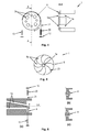
- Fig. 1
- ein erstes Ausführungsbeispiel einer erfindungsgemäßen Einrichtung zum Steuern eines Betriebszustandes einer Düse;
- Fig. 2
- ein Ausführungsbeispiel einer erfindungsgemäßen Einrichtung zum Steuern eines Betriebszustandes und/oder eines Wasseraustrittswinkels der Düse;
- Fig. 3
- ein Ausführungsbeispiel einer erfindungsgemäßen Einrichtung zum Steuern eines Betriebszustandes einer Düse;
- Fig. 4
- ein weiteres Beispiel einer erfindungsgemäßen Einrichtung zum Steuern eines Betriebszustandes und/oder eines Querschnittes der Austrittsöffnung einer Düse;
- Fig. 5
- ein Beispiel einer erfindungsgemäßen Einrichtung zum Steuern eines Querschnittes einer Wasseraustrittsöffnung einer Düse;
- Fig. 6
- ein Beispiel einer erfindungsgemäßen Einrichtung zum Steuern des Betriebszustandes und/oder des Wasseraustrittswinkels einer Düse;
- Fig. 7
- ein Beispiel einer erfindungsgemäßen Einrichtung zum Steuern einer Drehung eines Düsenrings;
- Fig. 8
- ein weiteres Beispiel einer erfindungsgemäßen Einrichtung zum Steuern einer Drehung eines Düsenringes;
- Fig. 9
- ein Beispiel eines erfindungsgemäßen Spülkopfes, in dem zusätzlich eine Bildaufnahmeeinrichtung angeordnet ist;
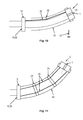
- Fig. 10
- ein Beispiel einer erfindungsgemäßen Einrichtung zum Steuern einer Düse, wobei der Spülkopf an einem Spülschlauch angeordnet ist;
- Fig. 11
- eine vorteilhafte Weiterbildung des in
Fig. 10 gezeigten Spülschlauches; und - Fig. 12
- ein noch weiteres Beispiel einer erfindungsgemäßen Einrichtung zum Steuern einer Düse.
-
Fig. 1 zeigt ein Beispiel einer erfindungsgemäßen Einrichtung zum Steuern einer Düse 1, insbesondere eines Spülkopfes eines Inspektions- und/oder Reinigungssystems. Die Düse weist ein Düsengehäuse auf, in dem ein Fluidkanal bzw. Wasserkanal 1a ausgebildet ist, durch den ein Fluid, vorzugsweise Wasser, hindurchströmt, welches vorzugsweise unter Druck dem Spülkopf zugeführt wird, beispielsweise über einen Spülschlauch. In dem Fluidkanal bzw. Wasserkanal 1a ist ein Bolzen 3 angeordnet, der im Wesentlichen zylinderförmig ausgestaltet ist. Der Bolzen ist so relativ zu dem Wasserkanal 1a angeordnet, dass der zylinderförmige Bolzen im Wesentlichen quer zum Wasserkanal 1a liegt. Der Durchmesser des Bolzens ist hierbei größer als der Durchmesser des Wasserkanals 1a, der vorzugsweise einen zylinderförmigen Querschnitt aufweist. - In dem Bolzen 3 ist ein dem Bolzen durchdringender Kanal 3a ausgebildet, wobei der Kanal 3a quer durch den Bolzen verläuft. Der Kanal 3a kann einen runden Querschnitt aufweisen. Allerdings kann der Kanal 3a auch andere Querschnittsformen aufweisen. In dem hier gezeigten Beispiel ist der Durchmesser des Kanals 3a im Wesentlichen gleich groß wie der Durchmesser des Wasserkanals 1a. Er kann aber auch größer oder kleiner sein als der Durchmesser des Wasserkanals 1a.
- Der Bolzen 3 ist um seine Längsachse drehbar in dem Wasserkanal 1a bzw. in dem Düsengehäuse gelagert. Dadurch kann durch Drehen des Bolzens 3 ein Wasseraustritt aus der Düse gesperrt oder freigegeben werden. Durch Drehen des Bolzens derart, dass der Kanal 3a des Bolzens im Wesentlichen senkrecht zur Längsachse LA des Wasserkanals 1a der Düse 1 steht, wird ein Durchströmen des Wassers durch den Wasserkanal 1a blockiert.
- Dem Bolzen 3 ist ein Stellmittel zugeordnet, mit dem der Bolzen in eine Richtung gedreht werden kann. Ferner ist dem Bolzen 3 ein Rückstellmittel 13 zugeordnet, mit dem der Bolzen in die entgegengesetzte Richtung gedreht werden kann. Das Rückstellmittel 13 ist hier als Federelement ausgestaltet und stellt eine Rückstellkraft bereit, die entgegen der Stellkraft des Stellmittels wirkt.
- Erfindungsgemäß weist das Stellmittel ein Formgedächtniselement 20 auf, das hier als längliches Formgedächtniselement bzw. als länglicher Formgedächtnisdraht ausgebildet ist. Ferner weist das Stellmittel zusätzlich Zugelemente 21 auf, die jeweils mit dem Formgedächtniselement 20 und mit einer Befestigungseinheit 12 bzw. mit dem Bolzen 3 verbunden sind. Als Zugelemente 21 können beispielsweise Drähte, Seile oder dergleichen verwendet werden. Vorteilhaft ist es allerdings, wenn die Zugelemente 21 bei Einwirkung einer Zugkraft ihre Länge dauerhaft nicht verändern.
- Bei der in
Fig. 1 gezeigten Ausgestaltung des Stellmittels sowie auf die in den nachfolgenden Figuren gezeigten Stellmittel kann auf die Zugelemente 21 auch verzichtet werden und der Formgedächtnisdraht 20 kann direkt an dem Bolzen bzw. an den jeweiligen Steuermittel und an der Befestigungseinheit 12 befestigt sein. - Zum Drehen des Bolzen 3 wird das Stellmittel verkürzt, indem das Formgedächtniselement 20 mit einer physikalischen Größe beaufschlagt wird, die eine Formänderung des Formgedächtniselements 20 bewirkt. Die Formänderung des Formgedächtniselements 20 ist vorzugsweise dergestalt, dass sich die Länge des Formgedächtniselementes reduziert und das Stellmittel dadurch eine Zugkraft auf dem Bolzen ausübt, die ein Drehen des Bolzens bewirkt. Wird das Formgedächtniselement 20 nicht mehr mit der physikalischen Größe beaufschlagt, kehrt das Formgedächtniselement 20 aufgrund der Rückstellkraft des Rückstellmittels 30 wieder in seine ursprüngliche Form bzw. Länge zurück, d.h. das Stellmittel verlängert sich wieder, sodass der Bolzen 3 nunmehr in die entgegengesetzte Richtung gedreht wird.
- Bei der in
Fig. 1 gezeigten Ausgestaltung der erfindungsgemäßen Einrichtung zum Steuern der Düse und bei den nachfolgend beschriebenen Ausgestaltungen einer erfindungsgemäßen Einrichtung zum Steuern einer Düse werden für das Formgedächtniselement solche Materialien verwendet, die bei einer Temperaturveränderung, beispielsweise bei einer Temperaturerhöhung ihre Form bzw. Länge verändern. Vorzugsweise ist das Formgedächtniselement so ausgestaltet, dass sich die Länge bei einer Temperaturerhöhung verringert. Es können aber auch Formgedächtniselemente verwendet werden, bei denen eine Temperaturerhöhung eine Vergrößerung der Länge des Formgedächtniselementes bewirkt. - Die Verwendung von Formgedächtniselementen als Stellmittel oder Bestandteil des Stellmittels hat den Vorteil, dass dadurch sehr hohe Stellkräfte bei sehr geringem Materialeinsatz und insbesondere bei sehr geringem Platzbedarf erreicht werden können. Damit kann eine besonders platzsparende Einrichtung zum Steuern einer Düse bereitgestellt werden. Zudem können sämtlichen Düsen eines Spülkopfes jeweils eine eigene Einrichtung zum Steuern zugeordnet werden, ohne den Spülkopf selbst wesentlich vergrößern zu müssen. Dadurch sind besonders platzsparende und kompakte Spülköpfe realisierbar, die dennoch einen möglichst großen Grad an Flexibilität hinsichtlich ihrer Einsatzmöglichkeiten bieten.
- Zudem unterliegen die Formgedächtniselemente keinem oder einem nur sehr geringem Verschleiß, wodurch die Wartungsintervalle für die Wartung von Spülköpfen erheblich verlängert werden können.
- Als besonders vorteilhaft hat sich herausgestellt, wenn für das Formgedächtniselement 20 Formgedächtnislegierungen oder Formgedächtnispolymere verwendet werden, die den sogenannten Zwei-Weg-Effekt aufweisen. D.h. beim Abkühlen wieder ihre ursprüngliche Form bzw. ursprüngliche Länge einnehmen. Vorteilhafte Formgedächtnislegierungen sind beispielsweise Nickel-Titan, Nickel-Titan-Kupfer, Kupfer-Zink, Kupfer-Zink-Aluminium, Kupfer-Aluminium-Nickel, Eisen-Nickel-Aluminium, Eisen-Mangan oder Zink-Gold-Kupfer.
- Die zur Formänderung bzw. zum Verkürzen des Formgedächtniselements 20 erforderliche Erwärmung kann beispielsweise über Widerstandselemente, über induktive Erwärmung oder dergleichen bewirkt werden. Beispielsweise kann die Beheizung des Formgedächtniselements 20 auf direktem Weg erfolgen, indem ein über das Formgedächtniselement 20 geführter Strom zu dessen Aufheizung aufgrund des ohmschen Widerstandes führt.
- In einer einfachen Form wird das Formgedächtniselement mit einem elektrischen Strom beaufschlagt, der eine entsprechende Erwärmung des Formgedächtniselements bewirkt. Hierzu kann das Formgedächtniselement 20 mit einer Steuer- und/oder Regeleinrichtung gekoppelt sein, die auf einer Platine angeordnet ist. Die Platine kann an der Befestigungseinheit 12 angeordnet sein und weist Anschlüsse für Steuer- und/oder Datenkabel auf. Über die Steuer-/Datenkabel kann die Steuer- und/oder Regeleinrichtung mit einer Kontrolleinrichtung verbunden sein, um die jeweilige Einrichtung zum Steuern der Düse zu steuern.
- Die Steuer- und/oder Regeleinrichtung kann alternativ auch über eine drahtlose Kommunikationsverbindung mit der Kontrolleinrichtung gekoppelt sein. Die drahtlose Kommunikationsverbindung hat den Vorteil, dass dem Spülkopf keine Steuer- und/oder Datenkabel zugeführt werden müssen, weil solche Kabel parallel zu dem Spülschlauch in das zu reinigende Rohr eingeführt werden müssen und einem besonders hohen Verschleiß unterliegen bzw. aufgrund der mechanischen Beanspruchung leicht reißen können. Es ist daher vorteilhaft, an dem Spülkopf ein Sende-/Empfangsmodul für die drahtlose Kommunikationsverbindung anzuordnen, das vorzugsweise ausgestaltet ist, eine WLAN-Kommunikationsverbindung aufzubauen.
- Für die Energieversorgung der Einrichtung zum Steuern der Düsen bzw. für das Sende-/Empfangsmodul kann entweder durch eine in die Spüldüse integrierte Stromversorgung, etwa Akkumulator, bereitgestellt werden. Alternativ kann die Energie von einer im Spülkopf angeordneten Wasserturbine bereitgestellt werden, die von dem dem Spülkopf zugeführten Spülwasser angetrieben wird.
- Das vorstehend zur Ausgestaltung des Stellmittels und insbesondere des Formgedächtniselements Gesagte gilt in entsprechender Weise auch für die Stellmittel bzw. Formgedächtniselemente, die in den Beispielen gemäß
Fig. 2 bis Fig. 12 verwendet werden. -
Fig. 2 zeigt ein weiteres Ausführungsbeispiel einer erfindungsgemäßen Einrichtung zum Steuern einer Düse. Das Steuermittel wird hier von einem Bolzen 3 gebildet, der mit Hilfe eines Stellmittels, das ein Formgedächtniselement 20 aufweist, in eine Richtung gedreht wird. Mit einem Rückstellmittel 13, dessen Rückstellkraft entgegen der Stellkraft des Stellmittels wirkt, wird der Bolzen in die entgegengesetzte Richtung gedreht. - In dem Bolzen 3 ist ein Kanal 3a ausgebildet, der hier zugleich den Wasseraustrittskanal der Düse bildet. Der Bolzen ist zylinderförmig ausgestaltet, wobei der Kanal 3a den Bolzen 3 in Querrichtung durchdringt. Die Lage des Bolzens 3 relativ zum Wasserkanal 1a entspricht der Lage des in
Fig. 1 gezeigten Bolzens. In Längsrichtung zum Wasserkanal 1a ist der Bolzen allerdings so in dem Düsengehäuse angeordnet, dass die Wasseraustrittsseite des Kanals 3a etwas außerhalb des Düsengehäuses liegt, sodass bei einer Drehung des Bolzens 3 der Austrittswinkel des aus dem Kanal 3a austretenden Spülwassers verändert wird. - Wassereintrittsseitig weist der Kanal 3a einen größeren Durchmesser auf als wasseraustrittsseitig. Insbesondere weist der Kanal 3a wassereintrittsseitig einen größeren Durchmesser auf als das wassereintrittsseitige Ende des Wasserkanals 1a der Düse 1. Dadurch wird gewährleistet, dass bei einem Drehen des Bolzens 3 dieser den Wasserkanal 1a nicht abdeckt und so einen Wasseraustritt durch den Kanal 3a verhindert.
-
Fig. 3 zeigt eine weitere Ausgestaltung einer erfindungsgemäßen Einrichtung zum Steuern einer Düse. Als Steuermittel ist hier ein Riegel 5 vorgesehen, der in Querrichtung zum Wasserkanal 1a der Düse 1 relativ zum Wasserkanal 1a verschiebbar ist. In Abhängigkeit der Verschiebeposition des Riegels 5 gibt dieser den Wasserdurchfluss durch den Wasserkanal 1a frei oder sperrt den Wasserdurchfluss durch den Wasserkanal 1a. InFig. 3 ist der Riegel 5 in einer Verschiebeposition gezeigt, bei der der Wasserdurchfluss durch den Wasserkanal 1a gesperrt ist und damit kein Wasser aus der Düse austreten kann. - In einer Entriegelungsposition, d.h. in einer Verschiebeposition, bei der der Riegel 5 den Wasseraustritt freigibt, befindet sich der Riegel in einer Aussparung, die ebenfalls quer zur Längsachse LA des Wasserkanals 1a verläuft.
- Zum Bewegen des Riegels 5 ist dieser mit einem Stellmittel, das ein Formgedächtniselement 20 aufweist, gekoppelt. Für eine Rückwärtsbewegung des Riegels 5 ist dieser mit einem Rückstellmittel, insbesondere mit einer Rückstellfeder 13 gekoppelt. Das Formgedächtniselement 20 ist hier so ausgestaltet, dass eine Temperaturbeaufschlagung zu einer Verkürzung des Formgedächtniselements 20 bzw. des Stellmittels führt und der Riegel 5 daher in die Entriegelungsposition gebracht wird. Die Rückstellfeder 13 ist dann als Druckfeder ausgestaltet, die den Riegel 5 wieder in die Verriegelungsposition bringt, wenn das Formgedächtniselement 20 nicht mehr mit einer Temperatur beaufschlagt wird.
- Alternativ zur vorstehenden Ausgestaltung des Verschiebemechanismus kann das Formgedächtniselement 20 auch so ausgestaltet sein, dass eine Temperaturbeaufschlagung des Formgedächtniselementes zu einer Verlängerung des Formgedächtniselementes 20 führt und dadurch der Riegel 5 in die Verriegelungsposition bewegt wird. Die Rückstellfeder 13 ist dann so ausgestaltet, dass sie den Riegel 5 wieder in die Entriegelungsposition bringt, wenn das Formgedächtniselement 20 nicht mehr mit einer Temperatur beaufschlagt wird.
-
Fig. 4 zeigt eine weitere Ausgestaltung einer erfindungsgemäßen Einrichtung zum Steuern einer Düse. Als Steuermittel ist hier eine Lochblende 6 vorgesehen, die wasserkanalausgangsseitig drehbar an der Düse 1 angeordnet ist. Die Lochblende 6 weist eine Anzahl von Löchern 3a auf, die die Lochblende vollständig durchdringen und dessen Mittelpunkt bei geeigneter Drehposition mit der Längsachse des Wasserkanals 1a der Düse 1 korrespondiert. In dieser Drehposition gibt das Loch 3a den Wasseraustritt aus dem Wasserkanal 1a frei. Eine solche Drehposition ist inFig. 4 gezeigt. - Die Löcher 3a der Lochblende 6 können jeweils einen unterschiedlichen Durchmesser aufweisen, sodass durch Drehen der Lochscheibe 6 der Querschnitt der Wasseraustrittsöffnung der Düse verändert werden kann. In
Fig. 4 ist eine Drehposition der Lochblende 6 gezeigt, bei der ein Wasseraustritt durch jene Löcher 3a erfolgt, die einen kleineren Durchmesser aufweisen. - Die Düse kann mehrere Wasserkanäle 1a aufweisen, wobei die kleineren Löcher und die größeren Löcher vorzugsweise jeweils so in der Lochblende angeordnet sind, dass bei einer bestimmten Drehposition der Lochblende einerseits sämtliche Wasserkanäle 1a geöffnet sind und andererseits sämtliche Wasseraustrittsöffnungen denselben Querschnitt aufweisen. Vorteilhaft ist es zudem, wenn die Lochscheibe 6 in eine solche Position drehbar ist, bei der sämtliche Wasseraustrittsöffnungen verschlossen sind. Dies kann beispielsweise dadurch geschehen, dass die Drehscheibe so verdreht wird, dass sich die Wasserkanäle 1a bzw. die Wasseraustrittsöffnungen der Wasserkanäle 1a jeweils zwischen zwei Löchern 3a der Lochscheibe 6 befinden.
- Das Stellmittel wird hier von einem Formgedächtniselement 20 gebildet, das an einer Befestigungseinheit 12 befestigt ist. An dem von der Befestigungseinheit 12 abgewandten Ende ist an dem Formgedächtniselement 20 ein Zugelement 21 befestigt, das in radialer Richtung um die Lochblende 6 herumgeführt ist. An dem anderen Ende ist das Zugelement 21 mit dem Rückstellmittel 13, das hier als Federelement ausgebildet ist, verbunden.
- Der um die Lochblende 6 geführte Abschnitt des Zugelements 21 und der hierzu korrespondierende Abschnitt der Lochblende 6 sind zumindest abschnittsweise als Riementrieb, vorzugsweise als Zahnriementrieb, ausgestaltet. Durch Ziehen des Zugelements 21 an einer der beiden Enden wird die Lochblende 6 in die entsprechende Richtung gedreht. Durch die Ausgestaltung des um die Lochblende 6 geführten Abschnitt des Zugelementes und des hierzu korrespondierenden Abschnitts der Lochblende als Riementrieb ist eine optimale Kraftübertragung zum Drehen der Lochblende gewährleistet, die bei den vorkommenden Wasserdrücken benötigt wird.
- Alternativ kann das an dem Formgedächtniselement 20 angeordnete Zugelement 21 auch teilweise um die Lochblende 6 geführt sein und an der Lochblende 6 befestigt sein. Die Rückstellfeder 13 kann ebenfalls teilweise in radialer Richtung um die Lochblende 6 geführt sein und an der Lochblende 6 befestigt sein. Das Wirkprinzip zum Drehen der Lochblende 6 entspricht hierbei im Wesentlichen dem vorstehend genannten Wirkprinzip, wobei hier allerdings aufgrund der Befestigung des Zugelementes 21 und des Federelementes 13 an der Lochblende auf eine riementriebartige Ausgestaltung des Zugelementes und der Lochblende verzichtet werden kann.
- Die in
Fig. 4 gezeigte Ausgestaltung des Stellmittels zusammen mit dem Rückstellmittel kann in entsprechender Weise auch zum Drehen der inFig. 1 und Fig. 2 gezeigten Bolzen 3 verwendet werden. -
Fig. 5 zeigt eine weitere erfindungsgemäße Ausgestaltung einer Einrichtung zum Steuern einer Düse. - Das Steuermittel wird hier von einer Blende bzw. Irisblende 8 gebildet, die eine Anzahl von Lamellen 8a aufweist. Durch Bewegen der Lamellen mit dem Stellmittel kann der Querschnitt der Wasseraustrittsöffnung vergrößert bzw. verkleinert werden. Den Lamellen 8a ist jeweils ein Formgedächtniselement 20, etwa ein Formgedächtnisdraht, zugeordnet, dessen Länge bei einer Temperaturbeaufschlagung reduziert wird und so ein Verschwenken der Lamellen radial nach außen bewirkt, sodass der Querschnitt der Wasseraustrittsöffnung vergrößert wird. Ein Verschwenken der Lamellen 8a radial nach innen wird jeweils mit einem den Lamellen zugeordnetes Rückstellmittel (in
Fig. 5 nicht gezeigt) bewerkstelligt. - Die Verwendung einer Irisblende 8 hat den Vorteil, dass der Querschnitt der Wasseraustrittsöffnung nahezu stufenlos vergrößert bzw. verkleinert werden kann.
-
Fig. 6 zeigt eine weitere erfindungsgemäße Ausgestaltung einer Einrichtung zum Steuern einer Düse. - Die Düse weist hier zwei Fluid- bzw. Wasserkanäle 1a auf, wobei der eine Wasserkanal um einen bestimmten Winkel geneigt relativ zum anderen Wasserkanal angeordnet ist. Der eine Wasserkanal ermöglicht dabei, dass der Austrittswinkel des austretenden Wassers verschieden vom Austrittswinkel des austretenden Wassers aus dem anderen Wasserkanal ist.
- Das Steuermittel wird hier von einem Schieber 4 gebildet, der wassereintrittsseitig der Wasserkanäle 1a angeordnet ist und in radialer Richtung relativ zur Düse bewegbar ist. Das Bewegen des Schiebers 4 in eine Richtung wird durch das Stellmittel bewirkt, während das Bewegen in die andere Richtung durch das Rückstellmittel 13 bewirkt wird.
- Der Schieber 4 weist hierbei eine Querschnittsfläche auf, die mindestens so groß ist wie der größere Querschnitt der beiden Wasserkanäle 1a. Damit ist gewährleistet, dass der Schieber 4 bei geeigneter Verschiebeposition den Wasseraustritt durch einen der beiden Wasserkanäle 1a verhindern kann.
- In Abbildung (a) ist ein Schieber 4 gezeigt, der in der dort gezeigten Verschiebeposition den unteren Wasserkanal der beiden Wasserkanäle 1a verschließt und damit einen Wasseraustritt aus dem unteren Wasserkanal verhindert.
- Der Schieber 4 kann auch so dimensioniert sein, dass er bei geeigneter Verschiebeposition einen Wasseraustritt aus beiden Wasserkanälen verhindert. In Abbildung (b) ist ein Schieber 4 gezeigt, der in der dort gezeigten Verschiebeposition beide Wasserkanäle 1a verdeckt und dadurch einen Wasseraustritt aus beiden Wasserkanälen 1a verhindert.
- In einer Ausgestaltung kann der Schieber 4 auch so dimensioniert sein, dass er bei einer geeigneten Verschiebeposition den Wasseraustritt aus beiden Wasserkanälen 1a freigibt. Ein entsprechend ausgestalteter Schieber 4 ist in Abbildung (c) gezeigt. Bei der in Abbildung (c) gezeigten Verschiebeposition des Schiebers 4 ist der Wasseraustritt aus beiden Wasserkanälen freigegeben. Durch ein Verschieben des Schiebers 4 nach oben bzw. nach unten wird der Wasseraustritt aus dem oberen Wasserkanal bzw. aus dem unteren Wasserkanal blockiert.
- Selbstverständlich können auch mehr als die in
Fig. 6 gezeigten Wasserkanäle vorgesehen sein. -
Fig. 7 zeigt ein Beispiel einer erfindungsgemäßen Einrichtung zum Steuern einer Düse. - Die Düsen sind hier an einem Düsenring angeordnet, sodass das Wasser im Wesentlichen in radialer Richtung relativ zum Düsenring 7 aus den Wasserkanälen 1a entweicht. Der Düsenring 7 kann drehbar an einem Spülkopf angeordnet sein, sodass der Austrittswinkel des aus den Düsen austretenden Wassers relativ zum Spülkopf verändert werden kann. Zum Einstellen eines vorbestimmten Austrittswinkels wird der Düsenring 7 so lange gedreht, bis der entsprechende Austrittswinkel erreicht ist. In dieser Position wird der Düsenring 7 mit Hilfe von zwei Bremsbacken 9 blockiert, sodass der Düsenring sich nicht weiter drehen kann. Die Bremsbacken sind in axialer Richtung versetzt zu den Wasserkanälen 1a angeordnet, sodass die Bremsbacken 9 den Wasseraustritt aus den Düsen 1a nicht behindern.
- Bei der in
Fig. 7 gezeigten Ausgestaltung sind die Bremsbacken 9 innerhalb des Düsenringes angeordnet und werden beim Bremsen gegen die Innenwandung des Düsenringes gepresst. In einer alternativen Ausgestaltung können die Bremsbacken 9 auch außerhalb des Düsenringes angeordnet werden und beim Bremsen gegen eine Außenwandung des Düsenringes gepresst werden. - Bei der in
Fig. 7 gezeigten Ausgestaltung wird der Anpressdruck durch das Rückstellmittel 13, das hier als Druckfeder ausgestaltet ist, bereitgestellt. Das Lösen der Bremsbacken, d.h. das Freigeben des Düsenringes 7, wird durch die Stellmittel bewerkstelligt, die jeweils ein Formgedächtniselement, insbesondere einen Formgedächtnisdraht 20 aufweisen, dessen Länge bei einer Temperaturbeaufschlagung reduziert wird. Bei Reduzierung der beaufschlagten Temperatur nimmt die Länge der Formgedächtniselemente 20 wieder zu und das Rückstellmittel 13 presst die Bremsbacken 9 wieder gegen die Innenwandung des Düsenrings. - In einer alternativen Ausgestaltung kann zwischen den beiden Bremsbacken 9 auch ein Formgedächtniselement 20 angeordnet sein, dessen Länge sich bei einer Temperaturbeaufschlagung vergrößert, sodass das aktivierte Formgedächtniselement die beiden Bremsbacken 9 gegen den Düsenring 7 presst. Das Rückstellmittel 13 ist in diesem Fall als Zugfeder ausgestaltet, die die Bremsbacken 9 wieder löst, wenn die Formgedächtniselemente 20 nicht mehr mit einer Temperatur beaufschlagt werden.
-
Fig. 8 zeigt eine weitere Ausgestaltung einer erfindungsgemäßen Einrichtung zum Steuern einer Düse. Die Düsen 1 sind hier ebenfalls an einem Düsenring 7 angeordnet, wie mit Bezug aufFig. 7 erläutert. Anstelle von Bremsbacken ist hier allerdings ein Riegel 5 als Steuermittel vorgesehen, das in radialer Richtung relativ zum Düsenring bewegbar ist. In einer Verriegelungsposition greift der Riegel 5 in eine Aussparung 5a im Düsenring 7 ein, sodass ein Drehen des Düsenrings verhindert wird. In einer Verriegelungsposition wird der Düsenring 7 für ein Drehen freigegeben. Das Stellmittel kann entweder radial innerhalb des Düsenringes oder radial außerhalb des Düsenringes 7 angeordnet sein, wobei die Aussparung 5a entsprechend an der Innenwandung des Düsenringes oder an der Außenwandung des Düsenringes 7 vorgesehen ist. - Bei der in
Fig. 8 gezeigten Ausgestaltung des Stellmittels weist dieses ein Formgedächtniselement 20 auf, das über Zugelemente mit dem Riegel 5 bzw. mit einer Befestigungseinheit verbunden ist. Ein Aktivieren des Formgedächtniselements 20, d.h. bei einer Temperaturbeaufschlagung des Formgedächtniselements, wird der Riegel 5 von der Verriegelungsposition in die Entriegelungsposition bewegt. Ein Bewegen des Riegels 5 von der Entriegelungsposition in die Verriegelungsposition folgt mit einem Rückstellmittel, das als Druckfeder ausgestaltet sein kann (inFig. 8 nicht gezeigt). - In einer alternativen Ausgestaltung kann ein Formgedächtniselement 20 vorgesehen sein, das direkt mit dem Riegel 5 und mit der Befestigungseinheit 12 gekoppelt ist und dessen Länge sich bei einer Temperaturbeaufschlagung vergrößert. Das Formgedächtniselement bewegt dann bei einer Temperaturbeaufschlagung den Riegel 5 von der Entriegelungsposition in die Verriegelungsposition. Entsprechend ist ein Rückstellmittel 13 vorgesehen, das den Riegel 5 von der Verriegelungsposition in die Entriegelungsposition bringt.
-
Fig. 9 zeigt einen erfindungsgemäßen Spülkopf, in dem mehrere Düsen 1 angeordnet sind. Die Düsen 1 können jeweils mit einer erfindungsgemäßen Einrichtung gesteuert werden. - Ferner ist an der Vorderseite des Spülkopfes 2 eine Aussparung vorgesehen, in der eine Bildaufnahmeeinrichtung 10 angeordnet werden kann. Vorzugsweise kann die Bildaufnahmeeinrichtung 10 lösbar in dieser Aussparung angeordnet werden, sodass die Bildaufnahmeeinrichtung einfach gewechselt werden kann. Die Bildaufnahmeeinrichtung kann eine Videokamera oder eine Bildkamera umfassen.
- Vor der Aussparung für die Bildaufnahmeeinrichtung 10 ist eine Schutzklappe 11 angeordnet, die beispielsweise während eines Spülvorganges geschlossen werden kann, um die in der Aussparung angeordnete Bildaufnahmeeinrichtung 10 zu schützen. Die Schutzklappe 11 kann aus einem transparenten Material gefertigt sein.
- Die Schutzklappe 11 ist mit einem Stellmittel gekoppelt, das ein Formgedächtniselement 20 aufweist. Über ein Zugelement 21 ist das Formgedächtniselement 20 mit der Schutzklappe verbunden. Wird das Formgedächtniselement 20 mit einer Temperatur beaufschlagt, verringert sich die Länge des Formgedächtniselements 20 und die schwenkbar an dem Spülkopf angelenkte Schutzklappe 11 wird geöffnet. Zudem ist die Schutzklappe 11 mit einem Rückstellmittel, etwa eine Rückstellfeder 13, gekoppelt, die die Schutzklappe 11 wieder schließt, wenn das Formgedächtniselement 20 nicht mehr mit einer Temperatur beaufschlagt wird. Die Rückstellfeder 13 kann auch direkt an der Schwenkachse angeordnet sein.
- In der hier gezeigten Ausgestaltung wird das Zugelement 21 an einer Umlenkrolle umgelenkt und zur Schutzklappe geführt.
- Zum Schutz der in der Aussparung angeordneten Bildaufnahmeeinrichtung kann auch eine mit Bezug auf
Fig. 5 gezeigte Irisblende vorgesehen werden, wobei die Irisblende mindestens so weit geöffnet werden kann, dass das Blickfeld der Bildaufnahmeeinrichtung 10 nicht beeinträchtigt wird. -
Fig. 10 zeigt eine weitere erfindungsgemäße Ausgestaltung einer Einrichtung zum Steuern einer Düse. In dem Spülkopf 2 ist die Düse 1 angeordnet. Der Spülkopf kann mehrere Düsen aufweisen, wobei der Querschnitt der Wasserkanäle der Düsen unterschiedlich ausgestaltet sein kann und wobei die Wasserkanäle der Düsen unterschiedlich ausgerichtet sein können. - Der Spülkopf 2 ist an einem vorderen Ende eines flexiblen Spülschlauches angeordnet. In dem Spülschlauch 40 ist ein Wasserkanal ausgebildet, durch den das Spülwasser dem Spülkopf zugeführt wird. Am anderen Ende des Spülschlauches 40 ist dieser an einer Befestigungseinheit 12 befestigt, die eine Bohrung aufweist, durch die das Spülwasser dem Spülschlauch zugeführt werden kann.
- In der Wandung des Spülschlauches ist ein Formgedächtniselement, insbesondere ein Formgedächtnisdraht, angeordnet, der einerseits mit der Befestigungseinheit 12 und andererseits an einer weiteren Befestigungseinheit am vorderen Ende des Spülschlauches oder an dem an dem vorderen Ende des Spülschlauches befestigten Spülkopf befestigt ist. Durch Beaufschlagung des Formgedächtniselements 20 mit einer Temperatur verringert sich die Länge des Formgedächtniselements. Aufgrund der reduzierten Länge des Formgedächtniselements wird der Spülschlauch nach oben gebogen. Mit einem Rückstellmittel 13, das hier als Rückstellfeder ausgebildet ist, wird der Spülschlauch 40 wieder in eine Neutralstellung gebracht, wenn das Formgedächtniselement 20 nicht mehr mit einer Temperatur beaufschlagt wird.
- Anstelle einer Rückstellfeder 13 kann in dem Spülschlauch auch ein Biegestab angeordnet sein, der eine gewisse Rückstellkraft aufweist. Nach dem Auslenken des Spülschlauches aus seiner Neutralstellung bewirkt die Rückstellkraft des Biegestabes, dass der Schlauch wieder in seine Neutralstellung gebracht wird. In einer alternativen Ausgestaltung kann der Spülschlauch 40 selbst eine gewisse Rückstellkraft aufweisen, sodass der Spülschlauch selbstständig wieder in seine Neutralstellung zurückkehren kann, wenn das Formgedächtniselement 20 nicht mehr mit einer Temperatur beaufschlagt wird.
-
Fig. 11 zeigt eine weitere Ausgestaltung einer erfindungsgemäßen Einrichtung zum Steuern einer Düse. Der grundsätzliche konstruktive Aufbau entspricht im Wesentlichen dem inFig. 10 gezeigten Ausführungsbeispiel. Im Unterschied zu dem inFig. 10 gezeigten Ausführungsbeispiel weist das Stellmittel hier zwei Formgedächtniselemente bzw. Formgedächtnisdrähte 20 auf, die jeweils mit der Befestigungseinheit 12 und mit der Spüldüse 2 verbunden sind und in radialer Richtung außerhalb der Längsachse des Spülschlauches angeordnet sind bzw. in der Wandung des Spülschlauches eingearbeitet sind. Durch Vorsehen von zwei Formgedächtnisdrähten 20 kann der Spülschlauch in zwei Richtungen gebogen bzw. ausgelenkt werden, nämlich in Richtung des ersten Formgedächtnisdrahtes und in Richtung des zweiten Formgedächtnisdrahtes. Werden beide Formgedächtniselemente 20 gleichzeitig erhitzt, sodass sich die beiden Formgedächtniselemente gleich stark oder unterschiedlich stark verkürzen, kann der Spülschlauch 40 auch in eine Richtung ausgelenkt bzw. gebogen werden, die zwischen den beiden Formgedächtniselementen liegt. - Bei der in
Fig. 6 gezeigten Ausgestaltung weist der Spülschlauch 40 eine Anzahl (hier zwei) von Führungsmitteln 24 auf, die als Führungsscheiben ausgebildet sein können und die für jedes Formgedächtniselement eine Bohrung aufweisen, die im Wesentlichen parallel zur Längsachse des Spülschlauches verlaufen. Durch diese Bohrungen werden die Formgedächtnisdrähte 20 hindurchgeführt. Die Führungsmittel bzw. Führungsringe 24 sind vorzugweise in die Wandung des Spülschlauches 40 eingearbeitet. - Die Formgedächtniselemente bzw. die Formgedächtnisdrähte 20 verlaufen innerhalb der Wandung des Spülschlauches in einem dafür vorgesehenen Kanal, der einen Durchmesser aufweist, der größer als der Durchmesser der Formgedächtnisdrähte ist. Mit den Führungsmitteln bzw. Führungsringen wird gewährleistet, dass die Formgedächtnisdrähte beim Erhitzen und beim Abkühlen sowie bei einer Neutralstellung des Spülschlauches 40 immer auf einer vorgegebenen Bahn innerhalb der Kanäle für die Formgedächtnisdrähte verlaufen.
- Bei Vorsehen von drei Formgedächtniselementen bzw. Formgedächtnisdrähten 20, die in radialer Richtung gleichmäßig an dem Spülschlauch bzw. in der Wandung des Spülschlauches angeordnet sind, kann der Spülschlauch 40 im Umkreis von 360° in jede beliebige Richtung und im Wesentlichen um jede beliebige Amplitude ausgelenkt werden, wobei die gewünschte Auslenkrichtung und Auslenkamplitude durch eine entsprechend Erwärmung der jeweiligen Formgedächtnisdrähte 20 erreicht wird. Es können auch mehr als drei Formgedächtnisdrähte vorgesehen sein, um ein Auslenken bzw. Abbiegen des Spülschlauches in jede beliebige Richtung zu ermöglichen. Werden die drei Formgedächtnisdrähte 20 gleich stark erhitzt, sodass die Formgedächtnisdrähte jeweils die gleiche Länge aufweisen, befindet sich der Spülschlauch in seiner Neutralstellung. Werden die drei Formgedächtnisdrähte nicht mehr mit einer Temperatur beaufschlagt, sorgt das Rückstellmittel (vgl. Beschreibung zu
Fig. 10 ) dafür, dass der Spülschlauch 40 wieder in seine Neutralstellung zurückkehrt. - In einer Ausgestaltung der Erfindung kann die Wandung des Spülschlauches selbst aus einem Formgedächtnismaterial bestehen. Dabei werden vorzugsweise Formgedächtnismaterialien verwendet, die den sogenannten Zwei-Weg-Memory-Effekt aufweisen. Beim Erwärmen der Spülschlauchwandung ändert sich die Form des Spülschlauches, sodass der an dem vorderen Ende des Spülschlauches angeordnete Spülkopf ausgelenkt wird. Beim Abkühlen der Spülschlauchwandung nimmt der Spülschlauch wieder seine ursprüngliche Form an und kehrt in seine Neutralstellung zurück. Das Zurückkehren in die Neutralstellung kann mit einem Rückstellmittel 13 unterstützt werden.
-
Fig. 12 zeigt eine noch weitere Ausgestaltung einer erfindungsgemäßen Einrichtung zum Steuern einer Düse. - In dem Wasserkanal 1a ist konzentrisch zur Längsachse des Wasserkanals ein Ring 16 angeordnet, der ein konzentrisches Durchgangsloch aufweist. Der Ring 16 greift in eine an der Innenwandung des Wasserkanals vorgesehene umlaufende Nut ein.
- Der Ring 16 ist aus einem Formgedächtnismaterial hergestellt. Bei Beaufschlagung des aus einem Formgedächtnismaterial bestehenden Ringes 16 mit einer Temperatur nimmt dieser eine Form an, bei der das Durchgangsloch des Ringes einen kleineren Durchmesser aufweist. Wird der Ring 16 nicht mehr mit einer Temperatur beaufschlagt, nimmt dieser wieder seine ursprüngliche Form ein und der Durchmesser des Durchgangsloches des Ringes vergrößert sich wieder.
- Vorteilhafter Weise werden hier solche Formgedächtnismaterialien verwendet, die den sogenannten Zwei-Weg-Memory-Effekt aufweisen. D.h., dass sich der Ring 16 an zwei Formen "erinnern" kann, nämlich an eine Form bei einer hohen Temperatur und an eine Form bei einer niedrigen Temperatur. Obwohl der Ring aus dem Formgedächtnismaterial beim Abkühlen keine Arbeit verrichten kann, müssen keine Rückstellmittel vorgesehen werden, weil der Ring beim Abkühlen auch keine Arbeit verrichten muss. Die Stellkraft des Ringes 16 beim Erhöhen der Temperatur ist ausreichend, um selbst bei einem unter hohem Druck aus dem Wasserkanal austretenden Wasser den Durchmesser des Durchgangsloches des Ringes zu verringern.
- Mit den vorstehend genannten erfindungsgemäßen Einrichtungen zum Steuern einer Düse können die Düsen besonders kompakt hergestellt werden. Gleichzeitig können der Betriebszustand, der Querschnitt der Austrittsöffnung und/oder der Austrittswinkel des aus der Düse austretenden Wassers an die jeweiligen Erfordernisse angepasst bzw. eingestellt werden. Damit sind besonders kompakt ausgestaltete und besonders flexibel einsetzbare Spülköpfe realisierbar. Zudem entfallen elektrische bzw. elektromechanische Stellmittel, sodass einerseits eine kostengünstigere Herstellung von Spülköpfen ermöglicht wird und andererseits die Spülköpfe weniger wartungsintensiv sind.
-
- 1
- Düse
- 1a
- Wasserkanal der Düse 1
- 2
- Spülkopf mit Düsen und ggf. einer Bildaufnahmeeinrichtung 10
- 3
- Bolzen mit Kanal 3a
- 3a
- Kanal im Bolzen 3 bzw. Loch in der Lochblende 6
- 4
- Schieber
- 5
- Riegel
- 5a
- Aussparung zur Aufnahme des Riegels 5
- 6
- Lochblende (Scheibe mit Kanäle 3a)
- 7
- Düsenring
- 8
- Blende (Irisblende)
- 8a
- Lamellen der Blende 8
- 9
- Bremsbacken
- 10
- Bildaufnahmeeinrichtung
- 11
- Schutzklappe
- 12
- Befestigungseinheit
- 13
- Rückstellmittel, z.B. Rückstellfeder
- 15
- Platine der Steuer- und/oder Regeleinrichtung
- 20
- Formgedächtniselement
- 21
- Zugelement (z.B. Draht oder Seil)
- 23
- Umlenkeinrichtung (z.B. Umlenkrolle)
- 24
- Führungsmittel
- 30
- Steuer- und/oder Regeleinrichtung
- 40
- Spülschlauch
- LA
- Längsachse
Claims (15)
- Einrichtung zum Steuern von zumindest einer Düse (1), insbesondere eines Spülkopfes (2) eines Inspektions- und/oder Reinigungssystems, wobei die Düse ein Düsengehäuse aufweist, in dem ein Fluidkanal (1a) ausgebildet ist, durch den ein der Düse unter Druck zugeführtes Fluid, insbesondere Wasser hindurchströmt, und wobei der Düse zumindest ein Formgedächtniselement (20) zugeordnet ist, mit dem ein Betriebszustand (auf/zu) des Fluidkanals, ein Querschnitt der Fluidaustrittsöffnung des Fluidkanals und/oder ein Austrittswinkel des aus der Düse austretenden Fluides einstellbar ist.
- Einrichtung nach Anspruch 1, wobei- der Düse ein Steuermittel (3; 4; 5; 6; 8; 9; 16; 40) zugeordnet ist, mit dem der Betriebszustand, der Querschnitt und/oder der Austrittswinkel einstellbar ist, und- das Steuermittel mit einem Stellmittel gekoppelt ist, um das Steuermittel relativ zum Düsengehäuse zu bewegen,wobei das Stellmittel zumindest teilweise durch das zumindest eine Formgedächtniselement (20) gebildet wird, wobei das Formgedächtniselement (20) in Abhängigkeit von zumindest einer Einflussgröße seine Form ändert, wobei die Formänderung des Formgedächtniselements (20) das Bewegen des Steuermittels relativ zum Düsengehäuse bewirkt.
- Einrichtung nach einem der vorhergehenden Ansprüche, wobei das Formgedächtniselement (20) ein längliches Formgedächtniselement umfasst, das in Abhängigkeit von der Einflussgröße seine Länge ändert und aufgrund der Längenänderung das Steuermittel mit einer Stellkraft beaufschlagt.
- Einrichtung nach einem der Ansprüche 2 bis 3, wobei das Stellmittel zusätzlich zumindest ein Zugelement (21) aufweist, welches einerseits mit dem Formgedächtniselement (20) und andererseits mit dem Steuermittel verbunden ist.
- Einrichtung nach einem der Ansprüche 2 bis 4, wobei die Einflussgröße die Temperatur des Formgedächtniselements (20) ist und wobei die für ein vorbestimmtes Bewegen des Steuermittels relativ zum Düsengehäuse benötigte Temperatur dem Formgedächtniselement (20) direkt oder indirekt beaufschlagbar ist, wobei das Formgedächtniselement (20) mit einer Steuer- und/oder Regeleinrichtung (30) gekoppelt ist, die angepasst ist, das Formgedächtniselement (20) mit der für ein vorbestimmtes Bewegen des Steuermittels relativ zum Düsengehäuse benötigten Temperatur zu beaufschlagen.
- Einrichtung nach dem vorhergehenden Anspruch, wobei die Steuer- und/oder Regeleinrichtung (30) angepasst ist, elektrischen Strom in das Formgedächtniselement (20) einzuspeisen oder durch das Formgedächtniselement (20) zu leiten, um es dadurch zu erwärmen.
- Einrichtung nach einem der vorhergehenden Ansprüche, wobei diese mindestens ein mit dem Steuermittel zusammenwirkendes Rückstellmittel (13) aufweist, wobei eine Rückstellkraft des Rückstellmittels (13) entgegen der Stellkraft des Stellmittels wirkt, wobei das Rückstellmittel (13) vorzugsweise zumindest ein Federelement umfasst.
- Einrichtung nach einem der Ansprüche 2 bis 7, wobei das Steuermittel einen zylinderförmigen Bolzen (3) umfasst, der zumindest teilweise in dem Fluidkanal (1a) und quer zum Fluidkanal (1a) und um seine Längsachse drehbar angeordnet ist und einen Durchmesser aufweist, der größer ist als der Durchmesser des Fluidkanals, wobei der Bolzen einen quer durch den Bolzen verlaufenden Kanal (3a) aufweist, wobei der Bolzen (3) mit dem Stellmittel von einer ersten Position, in der der Kanal (3a) des Bolzens den Fluidkanal (1a) der Düse (1) für ein Durchströmen des Fluides durch den Fluidkanal zumindest teilweise freigibt, in eine zweite Position, in der der Bolzen den Fluidkanal der Düse für ein Durchströmen des Fluides durch den Fluidkanal sperrt, drehbar ist.
- Einrichtung nach dem vorhergehenden Anspruch, wobei der Bolzen (3) so relativ zum Fluidkanal (1a) der Düse (1) angeordnet ist, dass der Kanal (3a) des Bolzens einen Wasseraustrittskanal der Düse bildet, wobei ein Drehen des Bolzens eine Änderung des Austrittswinkels des aus der Düse austretenden Fluides bewirkt und/oder wobei der Kanal (3a) des Bolzens (3) fluideintrittsseitig einen größeren Durchmesser aufweist als fluidaustrittsseitig, vorzugsweise einen größeren Durchmesser, als das dem Bolzen zugewandte Ende des Fluidkanals (1a) der Düse (1).
- Einrichtung nach einem der Ansprüche 2 bis 7, wobei- das Steuermittel einen Riegel (5) umfasst, der quer zum Fluidkanal (1a) der Düse (1) angeordnet ist und mit dem Stellmittel in radialer Richtung relativ Fluidkanal (1a) bewegbar ist, wobei der Riegel von einer ersten Position, in der der Riegel den Fluidkanal der Düse für ein Durchströmen des Fluides durch den Fluidkanal sperrt, in eine zweite Position, in der der Riegel den Fluidkanal der Düse für ein Durchströmen des Fluides durch den Fluidkanal zumindest teilweise freigibt, bewegbar ist, und/oder- das Steuermittel eine Lochblende (6) mit einem ersten Loch (3a) umfasst, die fluidkanalausgangsseitig drehbar an der Düse (1) angeordnet ist, wobei in einer ersten Drehposition der Lochblende relativ zur Düse das erste Loch (3a) mit einer Fluidaustrittsöffnung des Fluidkanals (1a) der Düse (1) korrespondiert und den Fluidaustritt aus dem Fluidkanal durch das erste Loch freigibt, und wobei in einer weiteren Drehposition der Lochblende relativ zur Düse (1) die Lochblende einen Fluidaustritt aus dem Fluidkanal verhindert, und/oder- das Steuermittel eine Blende (8), insbesondere eine Irisblende, mit mehreren relativ zueinander und quer zum Fluidkanal (1a) bewegbaren Lamellen (8a) umfasst, die fluidkanalausgangsseitig an der Düse (1) angeordnet ist, wobei zumindest eine der Lamellen (8a) mit dem Stellmittel gekoppelt ist und mit dem Stellmittel bewegbar ist, wobei ein Bewegen der Lamellen ein Vergrößern oder ein Verkleinern des Querschnittes der Fluidaustrittsöffnung der Düse bewirkt, und/oder- das Steuermittel einen Schieber (4) umfasst, der mit dem Stellmittel in radialer Richtung quer zur Längsachse (LA) der Düse (1) zwischen einer ersten Schieberposition und einer zweiten Schieberposition hin und her bewegbar ist, wobei in dem Düsengehäuse zumindest ein erster Fluidkanal und ein zweiter Fluidkanal ausgebildet sind, wobei bei der ersten Schieberposition der Schieber den Fluidaustritt aus dem ersten Fluidkanal verhindert und wobei bei der zweiten Schieberposition der Schieber den Fluidaustritt aus dem zweiten Fluidkanal verhindert, wobei der Schieber mit dem Stellmittel vorzugsweise in eine dritte Schieberposition, die zwischen der ersten Schieberposition und der zweiten Schieberposition liegt, bewegbar ist und wobei bei der dritten Schieberposition der Schieber den Fluidaustritt aus beiden Fluidkanälen verhindert oder den Fluidaustritt aus beiden Fluidkanälen freigibt, und/oder- das Düsengehäuse einen Düsenring (7) aufweist, in dem der Fluidkanal (1a) ausgebildet ist, wobei der Düsenring (7) in radialer Richtung drehbar auf dem Spülkopf gelagert ist und wobei das Steuermittel zumindest eine Bremsbacke (9) umfasst, die mit dem Stellmittel bewegbar ist und gegen einen Innenwandungsabschnitt des Düsenrings drückbar ist, um eine Drehung des Düsenring zu blockieren, und/oder- das Düsengehäuse einen Düsenring (7) umfasst, in dem der Fluidkanal (1a) ausgebildet ist, wobei der Düsenring in radialer Richtung drehbar auf dem Spülkopf gelagert ist und wobei das Steuermittel einen Riegel (5) umfasst, der mit dem Stellmittel relativ zur Düse in radialer Richtung nach außen und nach innen bewegbar ist, wobei der Düsenring eine Aussparung (5c) aufweist, in die der Riegel (5) in Eingriff bringbar ist, um ein Drehen des Düsenringes zu blockieren, und/oder- das Steuermittel einen Spülschlauch (40) umfasst, in dem ein Wasserkanal ausgebildet ist und an dessen vorderen Ende zumindest eine Düse oder ein Spülkopf angeordnet ist, wobei der Spülschlauch (40), insbesondere die Wandung des Spülschlauches, zumindest abschnittsweise das Formgedächtniselement aufweist, wobei ein Verkürzen des Formgedächtniselements (20) ein Biegen des Spülschlauches (40) bewirkt.
- Einrichtung nach einem der Ansprüche 1 bis 7, wobei das Formgedächtniselement (20) als Ring (19) ausgebildet ist, der koaxial zum Fluidkanal (1a) in dem Fluidkanal (1a) angeordnet ist, wobei der Ring (16) bei Beaufschlagung mit der Einflussgröße seine Form derart ändert, dass sich der Durchmesser des Ringloches verkleinert.
- Einrichtung nach einem der vorhergehenden Ansprüche, wobei das Formgedächtniselement (20) ein Formgedächtnismaterial mit einem Zwei-Weg-Memory-Effekt aufweist.
- Spülkopf (2), aufweisend zumindest eine Düse (1) und zumindest eine Einrichtung zum Steuern der Düse nach einem der vorhergehenden Ansprüche.
- Spülkopf, aufweisend zumindest eine Düse (1) und einen Aufnahmeraum, in dem eine Bildaufnahmeeinrichtung vorzugsweise lösbar anordenbar ist, wobei die Öffnung des Aufnahmeraumes mit einer, vorzugsweise schwenkbaren, Schutzklappe (11) weitgehend verschließbar ist, wobei der Schutzklappe ein Stellmittel zugeordnet ist und wobei das Stellmittel zumindest ein Formgedächtniselement (20) aufweist, welches in Abhängigkeit von zumindest einer Einflussgröße seine Form ändert, wobei die Formänderung des Formgedächtniselements (20) das Bewegen der Schutzklappe relativ zum Spülkopf bewirkt.
- Inspektions- und/oder Reinigungssystem, insbesondere Kanalinspektions- und/oder Reinigungssystem, aufweisend zumindest eine Düse und zumindest eine Einrichtung zum Steuern der Düse nach einem der Ansprüche 1 bis 12 und/oder aufweisend zumindest einen Spülkopf nach einem der Ansprüche 13 oder 14.
Applications Claiming Priority (1)
| Application Number | Priority Date | Filing Date | Title |
|---|---|---|---|
| DE202014105997.0U DE202014105997U1 (de) | 2014-12-11 | 2014-12-11 | Einrichtung zum Steuern von Düsen |
Publications (3)
| Publication Number | Publication Date |
|---|---|
| EP3031530A2 true EP3031530A2 (de) | 2016-06-15 |
| EP3031530A3 EP3031530A3 (de) | 2016-09-28 |
| EP3031530B1 EP3031530B1 (de) | 2021-10-20 |
Family
ID=54478569
Family Applications (1)
| Application Number | Title | Priority Date | Filing Date |
|---|---|---|---|
| EP15192302.6A Active EP3031530B1 (de) | 2014-12-11 | 2015-10-30 | Kanalreinigungssystem mit zumindest einer düse |
Country Status (3)
| Country | Link |
|---|---|
| US (1) | US20160167064A1 (de) |
| EP (1) | EP3031530B1 (de) |
| DE (1) | DE202014105997U1 (de) |
Cited By (3)
| Publication number | Priority date | Publication date | Assignee | Title |
|---|---|---|---|---|
| CN106827934A (zh) * | 2017-04-06 | 2017-06-13 | 贵州鸿图彩印包装有限责任公司 | 裱纸机上胶装置 |
| DE102017102965A1 (de) | 2017-02-15 | 2018-09-06 | Eisenmann Se | Applikationsvorrichtung und Applikationssystem |
| US20220371060A1 (en) * | 2021-05-21 | 2022-11-24 | Kent Brown | Adjustable Cleaning and Sanitizing Apparatus |
Families Citing this family (6)
| Publication number | Priority date | Publication date | Assignee | Title |
|---|---|---|---|---|
| US20190203124A1 (en) * | 2017-12-28 | 2019-07-04 | Exxonmobil Research And Engineering Company | Apparatus and method for cleaning a vessel |
| DE102020002468A1 (de) | 2020-04-15 | 2021-10-21 | Engelbert Homann | Leicht transportierbare universell einsetzbare Reinigungsvorrichtung und zuverlässig arbeitendes leicht handhabbares Reinigungsgerät zur Reinigung von Oberflächen jedweder Art sowie die Verwendung desselben |
| CN114178078A (zh) * | 2021-11-16 | 2022-03-15 | 常州市宝源汽车部件有限公司 | 一种汽车车灯用便于灯罩定位的喷涂装置 |
| CN115972230B (zh) * | 2023-03-20 | 2024-06-04 | 大研智能机器人(怀化)有限公司 | 一种防撞型智能机器人 |
| CN117211018B (zh) * | 2023-09-12 | 2026-03-27 | 青岛海森林发制品集团股份有限公司 | 一种用于制备具有形状记忆功能的发丝去浮色冲洗器 |
| CN118110261B (zh) * | 2024-04-30 | 2024-07-09 | 太原市政建设集团有限公司 | 一种道路桥梁排水管道的清理装置 |
Family Cites Families (12)
| Publication number | Priority date | Publication date | Assignee | Title |
|---|---|---|---|---|
| US2849530A (en) * | 1955-09-12 | 1958-08-26 | John H Fleet | Means for observing boreholes |
| US4675728A (en) * | 1985-03-01 | 1987-06-23 | C.T.S. Consulting Personnel Svcs., Inc. | Apparatus for performing internal inspection of piping |
| JPH1068979A (ja) * | 1996-08-29 | 1998-03-10 | Copal Co Ltd | カメラ用絞り機構 |
| DE10306714B4 (de) * | 2003-02-18 | 2005-03-31 | Bauer, Jens, Dipl.-Ing. | Gerät für Rohrinnenaufgaben |
| ITTO20030553A1 (it) * | 2003-07-17 | 2005-01-18 | Fiat Ricerche | Dispositivo di controllo del flusso di un fluido |
| US20060071088A1 (en) * | 2004-10-05 | 2006-04-06 | Paul Adams | Fuel cartridge with an environmentally sensitive valve |
| DE102004062241A1 (de) * | 2004-12-23 | 2006-07-13 | BSH Bosch und Siemens Hausgeräte GmbH | Betätigungsvorrichtung für Ventile |
| GB0809876D0 (en) * | 2008-05-30 | 2008-07-09 | The Technology Partnership Plc | Spray generator |
| DE202010002714U1 (de) * | 2010-02-24 | 2011-09-07 | Arnold Pläsier | Spülkopf und Spülvorrichtung |
| US20120080541A1 (en) * | 2010-10-04 | 2012-04-05 | Schnell John W | Nozzle closure device for a paint sprayer |
| CN102777674B (zh) * | 2011-05-10 | 2014-09-17 | 厦门松霖科技有限公司 | 高温保护阀及其应用之花洒 |
| US8852079B2 (en) * | 2012-02-27 | 2014-10-07 | Medtronic, Inc. | Valve assembly with shape memory member |
-
2014
- 2014-12-11 DE DE202014105997.0U patent/DE202014105997U1/de not_active Expired - Lifetime
-
2015
- 2015-10-30 EP EP15192302.6A patent/EP3031530B1/de active Active
- 2015-12-11 US US14/966,281 patent/US20160167064A1/en not_active Abandoned
Non-Patent Citations (1)
| Title |
|---|
| None |
Cited By (3)
| Publication number | Priority date | Publication date | Assignee | Title |
|---|---|---|---|---|
| DE102017102965A1 (de) | 2017-02-15 | 2018-09-06 | Eisenmann Se | Applikationsvorrichtung und Applikationssystem |
| CN106827934A (zh) * | 2017-04-06 | 2017-06-13 | 贵州鸿图彩印包装有限责任公司 | 裱纸机上胶装置 |
| US20220371060A1 (en) * | 2021-05-21 | 2022-11-24 | Kent Brown | Adjustable Cleaning and Sanitizing Apparatus |
Also Published As
| Publication number | Publication date |
|---|---|
| EP3031530B1 (de) | 2021-10-20 |
| DE202014105997U1 (de) | 2016-03-14 |
| US20160167064A1 (en) | 2016-06-16 |
| EP3031530A3 (de) | 2016-09-28 |
Similar Documents
| Publication | Publication Date | Title |
|---|---|---|
| EP3031530B1 (de) | Kanalreinigungssystem mit zumindest einer düse | |
| DE1947361A1 (de) | Vorrichtung zur Betaetigung von Jalousetten | |
| EP0855223A2 (de) | Rotordüsenkopf | |
| EP0897442B1 (de) | Vorrichtung zum ausbringen von beton | |
| EP0401481A1 (de) | Luftdurchlass | |
| EP3138716A1 (de) | Lufteinlass für ein kraftfahrzeug | |
| DE2554645A1 (de) | Automatische filtersieb-wechselvorrichtung fuer einen extruder | |
| DE10142047A1 (de) | Windabweiser mit Betätigungselement für ein Schiebedachsystem | |
| DE10217061A1 (de) | Durchflusseinsteller für strömende Medien | |
| DE102013108171B4 (de) | Befestigungsvorrichtung für eine Befestigung eines Arbeitsgeräts an einem Arbeitsfahrzeug | |
| DE102011084110B4 (de) | Mehrschicht-Strangpresse | |
| DE102015209504A1 (de) | Ausströmervorrichtung, insbesondere für ein Kraftfahrzeug | |
| EP3062679B1 (de) | Auslenkbewegungsübertragungseinrichtung, endoskopbiegesteuerung und endoskop | |
| EP0173169A1 (de) | Schwenkspanner | |
| DE202014105987U1 (de) | Abbiegeeinrichtung | |
| EP0619391A1 (de) | Eintragsystem für eine Luftwebmaschine | |
| DE102009060097A1 (de) | Abdeckungsvorrichtung | |
| DE102016219057A1 (de) | Vorrichtung zur Verstellung von Luftführungseinrichtungen und Karosseriestruktur | |
| EP3470570B1 (de) | Ventilvorrichtung zum leiten eines kondensats eines wäschepflegegerätes | |
| DE2823513A1 (de) | Rueckholmechanismus fuer die versorgungsleitung eines arbeitsgeraetes | |
| DE102019116716A1 (de) | Vereinzelungseinrichtung | |
| EP0803607B1 (de) | Biegeeinstellwalze | |
| WO2009016067A1 (de) | Vorrichtung zum auf- und abwickeln eines seils einer verstelleinrichtung in einem kraftfahrzeug auf eine seiltrommel | |
| EP2907717A2 (de) | Im Betrieb lösbare Klemmvorrichtung | |
| EP3812123A1 (de) | Kalibriervorrichtung für den einsatz in einer extrudieranlage für kunststoffrohre und extrudieranlage |
Legal Events
| Date | Code | Title | Description |
|---|---|---|---|
| PUAI | Public reference made under article 153(3) epc to a published international application that has entered the european phase |
Free format text: ORIGINAL CODE: 0009012 |
|
| AK | Designated contracting states |
Kind code of ref document: A2 Designated state(s): AL AT BE BG CH CY CZ DE DK EE ES FI FR GB GR HR HU IE IS IT LI LT LU LV MC MK MT NL NO PL PT RO RS SE SI SK SM TR |
|
| AX | Request for extension of the european patent |
Extension state: BA ME |
|
| RAP1 | Party data changed (applicant data changed or rights of an application transferred) |
Owner name: IPEK INTERNATIONAL GMBH |
|
| PUAL | Search report despatched |
Free format text: ORIGINAL CODE: 0009013 |
|
| AK | Designated contracting states |
Kind code of ref document: A3 Designated state(s): AL AT BE BG CH CY CZ DE DK EE ES FI FR GB GR HR HU IE IS IT LI LT LU LV MC MK MT NL NO PL PT RO RS SE SI SK SM TR |
|
| AX | Request for extension of the european patent |
Extension state: BA ME |
|
| RIC1 | Information provided on ipc code assigned before grant |
Ipc: G05D 23/02 20060101ALI20160824BHEP Ipc: B05B 12/00 20060101ALI20160824BHEP Ipc: G03B 37/00 20060101ALI20160824BHEP Ipc: E03F 7/12 20060101ALI20160824BHEP Ipc: B08B 9/04 20060101ALI20160824BHEP Ipc: B05B 1/16 20060101ALI20160824BHEP Ipc: B05B 1/32 20060101ALI20160824BHEP Ipc: B08B 9/049 20060101ALI20160824BHEP Ipc: F16K 31/00 20060101ALI20160824BHEP Ipc: B05B 1/30 20060101AFI20160824BHEP Ipc: B05B 15/06 20060101ALI20160824BHEP Ipc: B05B 15/08 20060101ALI20160824BHEP Ipc: E03F 9/00 20060101ALI20160824BHEP Ipc: G01M 3/00 20060101ALI20160824BHEP Ipc: G01N 21/954 20060101ALI20160824BHEP Ipc: B08B 9/043 20060101ALI20160824BHEP |
|
| STAA | Information on the status of an ep patent application or granted ep patent |
Free format text: STATUS: REQUEST FOR EXAMINATION WAS MADE |
|
| 17P | Request for examination filed |
Effective date: 20170328 |
|
| RBV | Designated contracting states (corrected) |
Designated state(s): AL AT BE BG CH CY CZ DE DK EE ES FI FR GB GR HR HU IE IS IT LI LT LU LV MC MK MT NL NO PL PT RO RS SE SI SK SM TR |
|
| REG | Reference to a national code |
Ref country code: DE Ref legal event code: R079 Ref document number: 502015015309 Country of ref document: DE Free format text: PREVIOUS MAIN CLASS: B05B0001300000 Ipc: B05B0015652000 |
|
| GRAP | Despatch of communication of intention to grant a patent |
Free format text: ORIGINAL CODE: EPIDOSNIGR1 |
|
| STAA | Information on the status of an ep patent application or granted ep patent |
Free format text: STATUS: GRANT OF PATENT IS INTENDED |
|
| RIC1 | Information provided on ipc code assigned before grant |
Ipc: F16K 31/02 20060101ALI20210422BHEP Ipc: B05B 15/68 20180101ALI20210422BHEP Ipc: B05B 15/658 20180101ALI20210422BHEP Ipc: B05B 15/652 20180101AFI20210422BHEP |
|
| INTG | Intention to grant announced |
Effective date: 20210514 |
|
| GRAS | Grant fee paid |
Free format text: ORIGINAL CODE: EPIDOSNIGR3 |
|
| GRAA | (expected) grant |
Free format text: ORIGINAL CODE: 0009210 |
|
| STAA | Information on the status of an ep patent application or granted ep patent |
Free format text: STATUS: THE PATENT HAS BEEN GRANTED |
|
| AK | Designated contracting states |
Kind code of ref document: B1 Designated state(s): AL AT BE BG CH CY CZ DE DK EE ES FI FR GB GR HR HU IE IS IT LI LT LU LV MC MK MT NL NO PL PT RO RS SE SI SK SM TR |
|
| REG | Reference to a national code |
Ref country code: GB Ref legal event code: FG4D Free format text: NOT ENGLISH |
|
| REG | Reference to a national code |
Ref country code: CH Ref legal event code: EP |
|
| REG | Reference to a national code |
Ref country code: DE Ref legal event code: R096 Ref document number: 502015015309 Country of ref document: DE |
|
| REG | Reference to a national code |
Ref country code: IE Ref legal event code: FG4D Free format text: LANGUAGE OF EP DOCUMENT: GERMAN |
|
| REG | Reference to a national code |
Ref country code: AT Ref legal event code: REF Ref document number: 1439476 Country of ref document: AT Kind code of ref document: T Effective date: 20211115 |
|
| REG | Reference to a national code |
Ref country code: LT Ref legal event code: MG9D |
|
| REG | Reference to a national code |
Ref country code: NL Ref legal event code: MP Effective date: 20211020 |
|
| PG25 | Lapsed in a contracting state [announced via postgrant information from national office to epo] |
Ref country code: RS Free format text: LAPSE BECAUSE OF FAILURE TO SUBMIT A TRANSLATION OF THE DESCRIPTION OR TO PAY THE FEE WITHIN THE PRESCRIBED TIME-LIMIT Effective date: 20211020 Ref country code: LT Free format text: LAPSE BECAUSE OF FAILURE TO SUBMIT A TRANSLATION OF THE DESCRIPTION OR TO PAY THE FEE WITHIN THE PRESCRIBED TIME-LIMIT Effective date: 20211020 Ref country code: FI Free format text: LAPSE BECAUSE OF FAILURE TO SUBMIT A TRANSLATION OF THE DESCRIPTION OR TO PAY THE FEE WITHIN THE PRESCRIBED TIME-LIMIT Effective date: 20211020 Ref country code: BG Free format text: LAPSE BECAUSE OF FAILURE TO SUBMIT A TRANSLATION OF THE DESCRIPTION OR TO PAY THE FEE WITHIN THE PRESCRIBED TIME-LIMIT Effective date: 20220120 |
|
| REG | Reference to a national code |
Ref country code: CH Ref legal event code: PL |
|
| PG25 | Lapsed in a contracting state [announced via postgrant information from national office to epo] |
Ref country code: IS Free format text: LAPSE BECAUSE OF FAILURE TO SUBMIT A TRANSLATION OF THE DESCRIPTION OR TO PAY THE FEE WITHIN THE PRESCRIBED TIME-LIMIT Effective date: 20220220 Ref country code: SE Free format text: LAPSE BECAUSE OF FAILURE TO SUBMIT A TRANSLATION OF THE DESCRIPTION OR TO PAY THE FEE WITHIN THE PRESCRIBED TIME-LIMIT Effective date: 20211020 Ref country code: PT Free format text: LAPSE BECAUSE OF FAILURE TO SUBMIT A TRANSLATION OF THE DESCRIPTION OR TO PAY THE FEE WITHIN THE PRESCRIBED TIME-LIMIT Effective date: 20220221 Ref country code: PL Free format text: LAPSE BECAUSE OF FAILURE TO SUBMIT A TRANSLATION OF THE DESCRIPTION OR TO PAY THE FEE WITHIN THE PRESCRIBED TIME-LIMIT Effective date: 20211020 Ref country code: NO Free format text: LAPSE BECAUSE OF FAILURE TO SUBMIT A TRANSLATION OF THE DESCRIPTION OR TO PAY THE FEE WITHIN THE PRESCRIBED TIME-LIMIT Effective date: 20220120 Ref country code: NL Free format text: LAPSE BECAUSE OF FAILURE TO SUBMIT A TRANSLATION OF THE DESCRIPTION OR TO PAY THE FEE WITHIN THE PRESCRIBED TIME-LIMIT Effective date: 20211020 Ref country code: LV Free format text: LAPSE BECAUSE OF FAILURE TO SUBMIT A TRANSLATION OF THE DESCRIPTION OR TO PAY THE FEE WITHIN THE PRESCRIBED TIME-LIMIT Effective date: 20211020 Ref country code: HR Free format text: LAPSE BECAUSE OF FAILURE TO SUBMIT A TRANSLATION OF THE DESCRIPTION OR TO PAY THE FEE WITHIN THE PRESCRIBED TIME-LIMIT Effective date: 20211020 Ref country code: GR Free format text: LAPSE BECAUSE OF FAILURE TO SUBMIT A TRANSLATION OF THE DESCRIPTION OR TO PAY THE FEE WITHIN THE PRESCRIBED TIME-LIMIT Effective date: 20220121 Ref country code: ES Free format text: LAPSE BECAUSE OF FAILURE TO SUBMIT A TRANSLATION OF THE DESCRIPTION OR TO PAY THE FEE WITHIN THE PRESCRIBED TIME-LIMIT Effective date: 20211020 |
|
| REG | Reference to a national code |
Ref country code: BE Ref legal event code: MM Effective date: 20211031 |
|
| REG | Reference to a national code |
Ref country code: DE Ref legal event code: R097 Ref document number: 502015015309 Country of ref document: DE |
|
| PG25 | Lapsed in a contracting state [announced via postgrant information from national office to epo] |
Ref country code: SM Free format text: LAPSE BECAUSE OF FAILURE TO SUBMIT A TRANSLATION OF THE DESCRIPTION OR TO PAY THE FEE WITHIN THE PRESCRIBED TIME-LIMIT Effective date: 20211020 Ref country code: SK Free format text: LAPSE BECAUSE OF FAILURE TO SUBMIT A TRANSLATION OF THE DESCRIPTION OR TO PAY THE FEE WITHIN THE PRESCRIBED TIME-LIMIT Effective date: 20211020 Ref country code: RO Free format text: LAPSE BECAUSE OF FAILURE TO SUBMIT A TRANSLATION OF THE DESCRIPTION OR TO PAY THE FEE WITHIN THE PRESCRIBED TIME-LIMIT Effective date: 20211020 Ref country code: MC Free format text: LAPSE BECAUSE OF FAILURE TO SUBMIT A TRANSLATION OF THE DESCRIPTION OR TO PAY THE FEE WITHIN THE PRESCRIBED TIME-LIMIT Effective date: 20211020 Ref country code: LU Free format text: LAPSE BECAUSE OF NON-PAYMENT OF DUE FEES Effective date: 20211030 Ref country code: EE Free format text: LAPSE BECAUSE OF FAILURE TO SUBMIT A TRANSLATION OF THE DESCRIPTION OR TO PAY THE FEE WITHIN THE PRESCRIBED TIME-LIMIT Effective date: 20211020 Ref country code: DK Free format text: LAPSE BECAUSE OF FAILURE TO SUBMIT A TRANSLATION OF THE DESCRIPTION OR TO PAY THE FEE WITHIN THE PRESCRIBED TIME-LIMIT Effective date: 20211020 Ref country code: CZ Free format text: LAPSE BECAUSE OF FAILURE TO SUBMIT A TRANSLATION OF THE DESCRIPTION OR TO PAY THE FEE WITHIN THE PRESCRIBED TIME-LIMIT Effective date: 20211020 Ref country code: BE Free format text: LAPSE BECAUSE OF NON-PAYMENT OF DUE FEES Effective date: 20211031 |
|
| PLBE | No opposition filed within time limit |
Free format text: ORIGINAL CODE: 0009261 |
|
| STAA | Information on the status of an ep patent application or granted ep patent |
Free format text: STATUS: NO OPPOSITION FILED WITHIN TIME LIMIT |
|
| PG25 | Lapsed in a contracting state [announced via postgrant information from national office to epo] |
Ref country code: LI Free format text: LAPSE BECAUSE OF NON-PAYMENT OF DUE FEES Effective date: 20211031 Ref country code: CH Free format text: LAPSE BECAUSE OF NON-PAYMENT OF DUE FEES Effective date: 20211031 |
|
| 26N | No opposition filed |
Effective date: 20220721 |
|
| PG25 | Lapsed in a contracting state [announced via postgrant information from national office to epo] |
Ref country code: IE Free format text: LAPSE BECAUSE OF NON-PAYMENT OF DUE FEES Effective date: 20211030 Ref country code: AL Free format text: LAPSE BECAUSE OF FAILURE TO SUBMIT A TRANSLATION OF THE DESCRIPTION OR TO PAY THE FEE WITHIN THE PRESCRIBED TIME-LIMIT Effective date: 20211020 |
|
| PG25 | Lapsed in a contracting state [announced via postgrant information from national office to epo] |
Ref country code: SI Free format text: LAPSE BECAUSE OF FAILURE TO SUBMIT A TRANSLATION OF THE DESCRIPTION OR TO PAY THE FEE WITHIN THE PRESCRIBED TIME-LIMIT Effective date: 20211020 |
|
| REG | Reference to a national code |
Ref country code: AT Ref legal event code: MM01 Ref document number: 1439476 Country of ref document: AT Kind code of ref document: T Effective date: 20211030 |
|
| PG25 | Lapsed in a contracting state [announced via postgrant information from national office to epo] |
Ref country code: AT Free format text: LAPSE BECAUSE OF NON-PAYMENT OF DUE FEES Effective date: 20211030 |
|
| PG25 | Lapsed in a contracting state [announced via postgrant information from national office to epo] |
Ref country code: IT Free format text: LAPSE BECAUSE OF FAILURE TO SUBMIT A TRANSLATION OF THE DESCRIPTION OR TO PAY THE FEE WITHIN THE PRESCRIBED TIME-LIMIT Effective date: 20211020 Ref country code: HU Free format text: LAPSE BECAUSE OF FAILURE TO SUBMIT A TRANSLATION OF THE DESCRIPTION OR TO PAY THE FEE WITHIN THE PRESCRIBED TIME-LIMIT; INVALID AB INITIO Effective date: 20151030 |
|
| PG25 | Lapsed in a contracting state [announced via postgrant information from national office to epo] |
Ref country code: CY Free format text: LAPSE BECAUSE OF FAILURE TO SUBMIT A TRANSLATION OF THE DESCRIPTION OR TO PAY THE FEE WITHIN THE PRESCRIBED TIME-LIMIT Effective date: 20211020 |
|
| PG25 | Lapsed in a contracting state [announced via postgrant information from national office to epo] |
Ref country code: MK Free format text: LAPSE BECAUSE OF FAILURE TO SUBMIT A TRANSLATION OF THE DESCRIPTION OR TO PAY THE FEE WITHIN THE PRESCRIBED TIME-LIMIT Effective date: 20211020 |
|
| PG25 | Lapsed in a contracting state [announced via postgrant information from national office to epo] |
Ref country code: MT Free format text: LAPSE BECAUSE OF FAILURE TO SUBMIT A TRANSLATION OF THE DESCRIPTION OR TO PAY THE FEE WITHIN THE PRESCRIBED TIME-LIMIT Effective date: 20211020 |
|
| PG25 | Lapsed in a contracting state [announced via postgrant information from national office to epo] |
Ref country code: TR Free format text: LAPSE BECAUSE OF FAILURE TO SUBMIT A TRANSLATION OF THE DESCRIPTION OR TO PAY THE FEE WITHIN THE PRESCRIBED TIME-LIMIT Effective date: 20211020 |
|
| PGFP | Annual fee paid to national office [announced via postgrant information from national office to epo] |
Ref country code: DE Payment date: 20251021 Year of fee payment: 11 |
|
| PGFP | Annual fee paid to national office [announced via postgrant information from national office to epo] |
Ref country code: GB Payment date: 20251022 Year of fee payment: 11 |
|
| PGFP | Annual fee paid to national office [announced via postgrant information from national office to epo] |
Ref country code: FR Payment date: 20251030 Year of fee payment: 11 |