EP3029964B1 - Method for improving audio experience for a user of an audio device - Google Patents
Method for improving audio experience for a user of an audio device Download PDFInfo
- Publication number
- EP3029964B1 EP3029964B1 EP14196430.4A EP14196430A EP3029964B1 EP 3029964 B1 EP3029964 B1 EP 3029964B1 EP 14196430 A EP14196430 A EP 14196430A EP 3029964 B1 EP3029964 B1 EP 3029964B1
- Authority
- EP
- European Patent Office
- Prior art keywords
- audio device
- remote client
- peripheral
- communication channel
- peripheral audio
- Prior art date
- Legal status (The legal status is an assumption and is not a legal conclusion. Google has not performed a legal analysis and makes no representation as to the accuracy of the status listed.)
- Active
Links
- 238000000034 method Methods 0.000 title claims description 30
- 238000004891 communication Methods 0.000 claims description 136
- 230000002093 peripheral effect Effects 0.000 claims description 127
- 230000000007 visual effect Effects 0.000 claims description 19
- 238000012546 transfer Methods 0.000 claims description 17
- 230000005672 electromagnetic field Effects 0.000 description 17
- 230000005236 sound signal Effects 0.000 description 16
- 238000001514 detection method Methods 0.000 description 13
- 230000005540 biological transmission Effects 0.000 description 8
- 238000005516 engineering process Methods 0.000 description 8
- 230000008901 benefit Effects 0.000 description 5
- 230000004044 response Effects 0.000 description 4
- 238000013459 approach Methods 0.000 description 2
- 230000000977 initiatory effect Effects 0.000 description 2
- 238000012986 modification Methods 0.000 description 2
- 230000004048 modification Effects 0.000 description 2
- 230000008859 change Effects 0.000 description 1
- 230000005684 electric field Effects 0.000 description 1
- 238000009434 installation Methods 0.000 description 1
- 230000003993 interaction Effects 0.000 description 1
- 230000003287 optical effect Effects 0.000 description 1
- 230000002123 temporal effect Effects 0.000 description 1
Images


Classifications
-
- H—ELECTRICITY
- H04—ELECTRIC COMMUNICATION TECHNIQUE
- H04R—LOUDSPEAKERS, MICROPHONES, GRAMOPHONE PICK-UPS OR LIKE ACOUSTIC ELECTROMECHANICAL TRANSDUCERS; DEAF-AID SETS; PUBLIC ADDRESS SYSTEMS
- H04R27/00—Public address systems
-
- H—ELECTRICITY
- H04—ELECTRIC COMMUNICATION TECHNIQUE
- H04W—WIRELESS COMMUNICATION NETWORKS
- H04W4/00—Services specially adapted for wireless communication networks; Facilities therefor
- H04W4/80—Services using short range communication, e.g. near-field communication [NFC], radio-frequency identification [RFID] or low energy communication
-
- H—ELECTRICITY
- H04—ELECTRIC COMMUNICATION TECHNIQUE
- H04L—TRANSMISSION OF DIGITAL INFORMATION, e.g. TELEGRAPHIC COMMUNICATION
- H04L65/00—Network arrangements, protocols or services for supporting real-time applications in data packet communication
- H04L65/1066—Session management
- H04L65/1083—In-session procedures
- H04L65/1094—Inter-user-equipment sessions transfer or sharing
-
- H—ELECTRICITY
- H04—ELECTRIC COMMUNICATION TECHNIQUE
- H04L—TRANSMISSION OF DIGITAL INFORMATION, e.g. TELEGRAPHIC COMMUNICATION
- H04L65/00—Network arrangements, protocols or services for supporting real-time applications in data packet communication
- H04L65/1066—Session management
- H04L65/1069—Session establishment or de-establishment
-
- H—ELECTRICITY
- H04—ELECTRIC COMMUNICATION TECHNIQUE
- H04L—TRANSMISSION OF DIGITAL INFORMATION, e.g. TELEGRAPHIC COMMUNICATION
- H04L65/00—Network arrangements, protocols or services for supporting real-time applications in data packet communication
- H04L65/1066—Session management
- H04L65/1083—In-session procedures
- H04L65/1086—In-session procedures session scope modification
-
- H—ELECTRICITY
- H04—ELECTRIC COMMUNICATION TECHNIQUE
- H04L—TRANSMISSION OF DIGITAL INFORMATION, e.g. TELEGRAPHIC COMMUNICATION
- H04L67/00—Network arrangements or protocols for supporting network services or applications
- H04L67/14—Session management
- H04L67/148—Migration or transfer of sessions
-
- H—ELECTRICITY
- H04—ELECTRIC COMMUNICATION TECHNIQUE
- H04W—WIRELESS COMMUNICATION NETWORKS
- H04W4/00—Services specially adapted for wireless communication networks; Facilities therefor
- H04W4/16—Communication-related supplementary services, e.g. call-transfer or call-hold
-
- H—ELECTRICITY
- H04—ELECTRIC COMMUNICATION TECHNIQUE
- H04W—WIRELESS COMMUNICATION NETWORKS
- H04W4/00—Services specially adapted for wireless communication networks; Facilities therefor
- H04W4/20—Services signaling; Auxiliary data signalling, i.e. transmitting data via a non-traffic channel
- H04W4/21—Services signaling; Auxiliary data signalling, i.e. transmitting data via a non-traffic channel for social networking applications
-
- H—ELECTRICITY
- H04—ELECTRIC COMMUNICATION TECHNIQUE
- H04W—WIRELESS COMMUNICATION NETWORKS
- H04W4/00—Services specially adapted for wireless communication networks; Facilities therefor
- H04W4/70—Services for machine-to-machine communication [M2M] or machine type communication [MTC]
-
- H—ELECTRICITY
- H04—ELECTRIC COMMUNICATION TECHNIQUE
- H04W—WIRELESS COMMUNICATION NETWORKS
- H04W76/00—Connection management
- H04W76/10—Connection setup
- H04W76/14—Direct-mode setup
-
- H—ELECTRICITY
- H04—ELECTRIC COMMUNICATION TECHNIQUE
- H04L—TRANSMISSION OF DIGITAL INFORMATION, e.g. TELEGRAPHIC COMMUNICATION
- H04L65/00—Network arrangements, protocols or services for supporting real-time applications in data packet communication
- H04L65/10—Architectures or entities
- H04L65/1016—IP multimedia subsystem [IMS]
-
- H—ELECTRICITY
- H04—ELECTRIC COMMUNICATION TECHNIQUE
- H04L—TRANSMISSION OF DIGITAL INFORMATION, e.g. TELEGRAPHIC COMMUNICATION
- H04L65/00—Network arrangements, protocols or services for supporting real-time applications in data packet communication
- H04L65/1066—Session management
- H04L65/1096—Supplementary features, e.g. call forwarding or call holding
-
- H—ELECTRICITY
- H04—ELECTRIC COMMUNICATION TECHNIQUE
- H04L—TRANSMISSION OF DIGITAL INFORMATION, e.g. TELEGRAPHIC COMMUNICATION
- H04L65/00—Network arrangements, protocols or services for supporting real-time applications in data packet communication
- H04L65/1066—Session management
- H04L65/1101—Session protocols
- H04L65/1104—Session initiation protocol [SIP]
-
- H—ELECTRICITY
- H04—ELECTRIC COMMUNICATION TECHNIQUE
- H04R—LOUDSPEAKERS, MICROPHONES, GRAMOPHONE PICK-UPS OR LIKE ACOUSTIC ELECTROMECHANICAL TRANSDUCERS; DEAF-AID SETS; PUBLIC ADDRESS SYSTEMS
- H04R2227/00—Details of public address [PA] systems covered by H04R27/00 but not provided for in any of its subgroups
- H04R2227/003—Digital PA systems using, e.g. LAN or internet
-
- H—ELECTRICITY
- H04—ELECTRIC COMMUNICATION TECHNIQUE
- H04R—LOUDSPEAKERS, MICROPHONES, GRAMOPHONE PICK-UPS OR LIKE ACOUSTIC ELECTROMECHANICAL TRANSDUCERS; DEAF-AID SETS; PUBLIC ADDRESS SYSTEMS
- H04R2420/00—Details of connection covered by H04R, not provided for in its groups
- H04R2420/07—Applications of wireless loudspeakers or wireless microphones
Definitions
- the invention relates to an audio device and in particular to a method for improving audio experience for a user of such an audio device.
- a common solution to overcome such problems is to increase the degree of loudness or the intensity of a sound, i.e. increase the volume of the sound that is emitted to and/or from the audio device. Such a solution may, however, disturb the environment of the audio device. An increased volume may lead to that sensitive information may be overheard by other persons than the user of the audio device. Increasing the volume of the sound may moreover introduce distortions such that quality of the auditory information that is transferred is reduced.
- US 2014/0087705 A1 discloses transfer of communication roles between devices, using technology such as near field communications ("NFC”), optical communication (e.g., barcodes), BlueTooth and so forth.
- NFC near field communications
- US 6,999,769 B1 further discloses a method for in-progress telephone call transfer between a wireless telephone and a wired telephone using a short-range communication control link.
- a temporary communication channel is established between the peripheral audio device and the remote client when they are in the vicinity of each other as it allows a user of the remote client and a user of the audio device to communicate via the peripheral audio device.
- audio data pertaining to audio signals are transferred more efficiently between the two users.
- An efficient selection of users, i.e. a limitation of the number of users, to which the temporary communication channel may be established, is further provided as the temporary communication channel is provided when the peripheral audio device is detected to be in the vicinity of the audio device. The load induced on the audio device is thereby reduced such that for instance the power consumption and/or the bandwidth that is required for operating the audio device are reduced.
- the transmission of audio between the remote client and the peripheral audio device is further less influenced by sounds in the environment of the audio device.
- An improved directionality of the emitted audio signal may be obtained.
- problems associated with emitted audio signals disturbing the environment of the audio device is reduced.
- the risk that sensitive information may be overheard by other persons than the user of the audio device is reduced.
- the term audio experience should be construed as the perceived audio signal that a user of the audio device experiences.
- the audio signal may comprise frequencies in the audio frequency range of about 20 to 20 000 Hz.
- the audio signal comprises at least one tone that is audible for a human.
- the audio signal may comprise a plurality of tones which are simultaneous or sequential in time.
- the audio signal may be emitted from a loudspeaker.
- audio data should be understood as data representing any audio signal.
- audio device should be understood as a device comprising one or more units being arranged to emit and/or record audio; that is, comprising a loudspeaker and/or microphone.
- the term communication channel refers to a channel through which information may be conveyed.
- the information may for example comprise data in the form of a digital bit stream which is transferred from one or several senders/transmitters to one or several receivers.
- the term vicinity should be understood as close by or nearby such that two objects being located in the vicinity of each other may efficiently communicate via interacting electromagnetic fields.
- the two objects may communicate via transmission of data via electromagnetic fields.
- the communication may be via wireless use of electromagnetic fields to transfer data such as in radio-frequency identification technologies where the distance between the objects corresponds to the wavelength of the electromagnetic fields used or multiples thereof.
- the communication may further be via short-range wireless communication utilizing electromagnetic near-fields such that the distance between the objects is sub-wavelength.
- the term vicinity may further be understood as a read range, i.e. the distance within which two objects may communicate efficiently via the interacting electromagnetic fields such that information may be read/received by at least one of the objects.
- the extent of the read range depends on a number of factors, including the frequency of the electromagnetic fields, typically radio waves, used for the communication, the size of the emitter/receiver of the electromagnetic fields, and the power output of the electromagnetic fields.
- the read range for radio-frequency identification technologies may therefore range, typically, from centimeters to decimeter distances for near-field communication and from decimeters to tens of meters for Bluetooth, Bluetooth low energy or radio-frequency identification technologies applications utilizing frequency bands from kHz to GHz.
- the communication may further be understood as transmission of visible electromagnetic fields, i.e. as photons, between the two objects such that visual information, e.g. a visual indication, may be read by for instance a camera of one of the objects communicating.
- the communication channel and/or the temporary communication channel may be a SIP call.
- the SIP call i.e. Session Initiation Protocol call, is advantageous as it allows for the use of communication protocols for controlling multimedia communication sessions over for example Internet Protocol, IP, networks.
- IP Internet Protocol
- at least one of the communication channels take advantage of a SIP service providing a SIP-based Voice over Internet Protocol, VoIP network.
- VoIP utilizes hardware and software to enable the use of an intranet or the Internet as the transmission medium for, for example, telephone calls by sending audio data in packets using IP rather than by traditional circuit transmissions. A more well controlled and flexible transfer of audio data is thereby achieved.
- the temporary communication channel may be maintained as long as the peripheral audio device is in the vicinity of the audio device.
- the temporary communication channel may be maintained during a predetermined time period. Reducing the duration of the temporary communication channel reduces, for example, constraints on power and/or bandwidth of the audio device and/or the peripheral audio device. New temporary communication channels may further be achieved without interference from previously established temporary communication channels.
- the detecting of a peripheral audio device in the vicinity of the audio device may be achieved via near-field communication, radio-frequency identification or Bluetooth. Efficient detection is thereby provided which may utilize existing standardized wireless radio frequency technologies.
- Radio-frequency identification, RFID utilizes unique identification of devices using radio waves.
- Near-field communication, NFC may be considered as a subclass of the RFID technology. More specifically, NFC is a branch of highfrequency (HF) RFID, both operating at the 13.56 MHz frequency. NFC is designed to offer secure data exchange, where a device using NFC is capable of being both an NFC reader and an NFC tag allowing NFC devices to communicate peer-to-peer.
- Bluetooth is also a wireless technology standard for exchanging data over short distances (using short-wavelength UHF radio waves. In other words, communication is achieved via wireless use of electromagnetic fields 124 to transfer data. A more secure communication between the audio device and the peripheral audio device is thereby obtained which for example reduces problems associated with eavesdropping.
- the detecting of a peripheral device in the vicinity of the audio device may be achieved via QR code, a barcode or a text.
- the QR code, the barcode or the text may be arranged at the peripheral device and/or at the audio device.
- a visual indication may be used to establish a temporary communication channel between a peripheral audio device and a remote client.
- the detecting of a peripheral device in the vicinity of the audio device may be achieved via a visual indication.
- a camera of the audio device and/or peripheral audio device may be arranged to detect the QR code, the barcode, or the text.
- the establishing of the temporary communication channel between the peripheral audio device and the remote client may comprise a transfer of a SIP call between the remote client and the audio device to a SIP call between the peripheral audio device and the remote client.
- SIP based communication between the user of the audio device and the user of the remote client is thereby achieved via the peripheral audio device and via the temporary communication channel.
- This is advantageous as the temporary communication channel provides a direct channel for transmission of audio data which improves the audio experience for a user of an audio device.
- the method may further comprise closing the communication channel between the audio device and the remote client after the temporary communication channel between the peripheral audio device and the remote client is established.
- communication between a user of the audio device and a user of the remote client is achieved only via the peripheral audio device and via the temporary communication channel.
- a more effective communication is thereby achieved and the constraints of the audio device are thereby reduced.
- a simpler audio device may thereby also be used.
- the method may further comprise providing an address identifying the remote client to the peripheral device.
- the method may further comprise providing an address identifying the peripheral device to the remote client.
- Transfer of the address of the audio device, the peripheral audio device and/or the remote client simplifies the detecting of the peripheral device in the vicinity of the audio device and moreover the establishment of the temporary communication channel.
- the audio device may be an intercommunication station of an intercommunication system.
- the term intercommunication station should be understood as a station which allows for a one- or two-way audible communication, also referred to as simplex or duplex communication respectively, between two separated locations.
- the duplex communication may be full-duplex or half-duplex.
- the intercommunication station thereby allows for point-to-point communication.
- the intercommunication station may for example allow a person speaking into the intercommunication station to be heard at a location being remote from the intercommunication station. A person being near the intercommunication station may further be communicated with via the intercommunication station.
- the peripheral device may be a cell phone, a personal digital assistant, a computer, a tablet computer or a headset for any of these devices.
- the method may further comprise transferring, via the temporary communication channel, visual data between the peripheral audio device and the remote client, wherein the visual data comprises a still image or a video sequence. Multimedia content may thereby be transferred via the temporary communication channel.
- Fig. 1 illustrates a system 100 arranged to improve the audio experience for a user of an audio device 102. This is achieved by providing efficient communication between a user of a remote client 104 and a user of the audio device 102 via a peripheral audio device 106.
- the remote client 104 is remotely located in relation to the audio device 102. In other words, the remote client 104 and the audio device 102 are separated by a distance such that their users cannot directly communicate with each other without the use of auxiliary devices.
- the audio device 102 and the remote client 104 are in communication via a communication channel 108.
- the communication channel 108 is established by exchange of data between transceiver units 110 and 112 of the audio device 102 and the remote client 104, respectively.
- the communication channel 108 thereby allows for information to be conveyed, i.e. transferred, between the remote client 104 and the audio device 102.
- the information may for example comprise data in the form of a digital bit stream.
- the communication channel 108 thereby allows for transfer of audio data, the audio data representing any audio signal emitted and/or received by loudspeakers 114, 116 and microphones 118, 120, of the audio device 102 and the remote client 104, respectively.
- the audio device 102 and the peripheral audio device 106 comprise detection units 122 arranged to transmit and/or receive electromagnetic fields 124 such that a detection of the peripheral audio device 106 being in the vicinity of the audio device 102 is achieved.
- the detection units 122 are arranged such that the audio device 102 and the peripheral audio device 106 efficiently communicate information 125 via the interaction of the electromagnetic fields 124 when the audio device 102 and the peripheral audio device 106 are in the vicinity of each other.
- the peripheral audio device 106 is for example brought to a location in the vicinity of the audio device 102 an efficient communication via the interacting electromagnetic fields 124 is achieved.
- the communication is achieved via wireless use of electromagnetic fields 124 to transfer data.
- the wireless use of the electromagnetic fields includes radio-frequency identification technologies utilizing short-range wireless communication where the distance between the objects is sub-wavelength, also referred to as near-field communication, NFC.
- NFC is advantageous as disturbance from and/or communication to/from other peripheral audio devices (now shown) are reduced.
- a more secure communication between the audio device 102 and the peripheral audio device 106 is thereby obtained which for example reduces problems associated with eavesdropping.
- the detection units 122 are active and may thereby receive or read information 125 as well as emit information 125 pertaining, for example, to the address of the audio device 102 or the peripheral audio device 106.
- Figure 1 illustrates that after the detection of the peripheral device 106, being in the vicinity of the audio device 102, information 125 may be transmitted between them.
- the information 125 may, for example, comprise a request 126 from the audio device 102 to the peripheral audio device 106 asking for an establishment of an additional communication channel (not shown).
- the peripheral audio device 106 may thereby send a response 128 to the audio device 102 comprising information such that the additional communication channel between the audio device 102 and the peripheral audio device 106 may be established.
- an address 130 of the remote client 104 may be sent from the audio device 102 to the peripheral audio device 106, this will be more discussed below in connection with Fig. 3a .
- a one-time proxy address could be used. That way, a visitor will not be able to connect to the remote client 104 later, unless she gets a new address 130 to the remote client 104.
- an address 131 of the peripheral audio device 106 may be sent to the remote client 104 via the audio device 106, this will be more discussed below in connection with Fig. 3b . This approach is preferred from a security perspective, since that does not give the peripheral audio device 106 access to the inside network on which the remote client is connected.
- An address 130 of the remote client 104 may further be sent from the audio device 102 to the peripheral audio device 106 such that the peripheral audio device 106 may, in order to establish communication between the peripheral device 106 and the remote client 104, send a request 132 to the remote client 104.
- a temporary communication channel 134 may thereby be established between the peripheral audio device 106 and the remote client 104 such that a user of the remote client 104 and a user of the peripheral audio device 106 may communicate over the temporary communication channel 134.
- the temporary communication channel 134 is established by communication between the transceiver unit 112 of the remote client 104 and a transceiver 136 of the peripheral audio device 106. It should, however, be noted that the remote client may comprise a plurality of transceivers which each may be used for the establishment of a communication channel.
- the communication channel 108 and the temporary communication channel 134 may be Session Initiation Protocol, SIP, calls.
- SIP Session Initiation Protocol
- the use of a SIP call is advantageous as it allows for the use of communication protocols for controlling multimedia communication sessions over for example Internet Protocol, IP, networks. Voice, and/or video calls may thereby utilize the established communication channels 108 and 134.
- the SIP further defines the format of the messages that are sent between the elements of the system 100.
- a data link is provided which allows an audio signal to be transformed into audio data, also referred to as IP data.
- analog audio signals are transformed into digital audio data which is transferred using SIP over the established communication channels 108 and 134.
- An advantage of using SIP is furthermore that SIP offers increased flexibility to add new connections, i.e.
- SIP calls may therefore be used for two-party (unicast) or multiparty (multicast or conference) sessions.
- Several users in the vicinity of the audio device may, as an example form a multicast session with a user of the remote client. This may be achieved via each user in the vicinity of the audio device establishing an individual temporary communication channel via their respective peripheral audio devices such that they are in simultaneous contact with the users of the remote client.
- a user of the audio device may correspondingly be in simultaneous contact with several users of the remote client.
- several users of the remote client may via temporal communication channels communicate with several users in the vicinity of the audio device such that a multiparty session is formed.
- the establishment of the temporary communication channel 134 between the peripheral audio device 102 and the remote client 104 may comprise a transfer of a SIP call between the remote client 104 and the audio device 102 to a SIP call between the peripheral audio device 106 and the remote client 104.
- the communication channel 108 between the audio device 102 and the remote client 104 may be closed after the temporary communication channel 134 between the peripheral audio device and the remote client has been established.
- the communication between the audio device 102 and the remote client 104 is achieved via the peripheral audio device 106 and more specifically via the temporary communication channel 134.
- the temporary communication channel 134 provides a direct channel for transmission of audio signals emitted and/or received by the loudspeaker 116 and microphones 120 of the remote client 104 and a loudspeaker 138 and a microphone 140 of the peripheral audio device 106.
- This improves the audio experience for a user of an audio device 102. Problems associated with the audio device 102 being affected by its environment are, moreover, mitigated.
- the peripheral audio device 106 may for example be placed closed to the ear of a user such that the acoustics of the location and objects in the environment of the user are less likely to influence the audio experience of the user. An improved transfer of auditory information is further achieved.
- the volume of sound of the audio signals emitted by the peripheral audio device 104 may thereby also be reduced compared to the volume of the audio device 102.
- An improved directionality of the emitted audio signal is further obtained.
- problems associated with emitted audio signals disturbing the environment of the audio device102 is reduced.
- the risk that sensitive information may be overheard by other persons than the user of the audio device is reduced.
- the temporary communication channel may be maintained as long as the peripheral audio device is in the vicinity of the audio device.
- the temporary communication channel may also be maintained during a predetermined time period. This reduces, for example, constraints on power and/or bandwidth of the audio device and/or the peripheral audio device. New temporary communication channels may further be achieved without interference from older temporary communication channels.
- the time period may vary depending on application of the audio device. The time period may for example vary between tens of seconds to several minutes.
- the former time period may be enough to allow for communication between a user of the remote client and a user of the peripheral audio device such that for example the identity and purpose of the user of the peripheral audio device is revealed to the user of the remote client. This is for example advantageous if the audio device is an intercommunication station such as a door station.
- the remote client may, based on the identification of the user of the peripheral audio device, allow passage through a door for the identified user. Longer time periods may for example be needed during installation and/or set up of an intercommunication station.
- the temporary communication channel is maintained as long as two of its users are using the temporary communication channel. According to yet other embodiments the temporary communication channel is maintained as long as it is not terminated by one of its users.
- one of the detection units describe above may be passive. This may be advantageous as the passive detection unit does not require any powering.
- the passive detector unit will, however, induce a change in the electromagnetic field of the active detection unit interacting with the passive detection unit. As a result a modulation of the electric field follows which allows information to be transmitted between the two detection units.
- This information may, for example, comprise the address of the remote client such that a temporary communication channel may be established based on the address.
- the distance between the audio device and the peripheral audio device may correspond to the wavelength of the electromagnetic fields used or multiples thereof such as in radio-frequency identification or Bluetooth applications. This increases the range within which peripheral audio devices may be detected in the vicinity of the audio device.
- SIP calls may further comprise transferring, via the temporary communication channel 134, of visual data between the peripheral audio device 106 and the remote client 104, wherein the visual data comprises a still image or a video sequence.
- the still image and/or the video sequence may be obtained by using a camera (not shown) of the remote client 104 and/or the peripheral audio device 106.
- SIP can be used for creating, modifying and terminating sessions consisting of one or several media streams.
- the audio device 102 and/or the remote client 104 may further (not shown) comprise a camera and/or a display such that multimedia content, i.e. images and/or video streams of images may be transmitted in addition to audio data via the communication channel 108.
- Visual indications may further be used to establish the temporary communication channel between the peripheral audio device and the remote client.
- the detecting of a peripheral device in the vicinity of the audio device may be achieved via a visual indication such as a Quick Response Code, QR code, a barcode or a text.
- Fig. 2 illustrates a display 200 of a peripheral audio device on which a QR code 202 is displayed. Capturing of the visual indication is made by a camera of an audio device in the vicinity of the peripheral audio device.
- the QR code 202 displays the instruction "Call +46 123 45 67 89", as further displayed as a text 204 on the display 200.
- the camera of the audio device thereby registers the visual indication and acquires the information, i.e. in this example an address to the peripheral audio device in the form of a telephone number.
- information is transmitted between the audio device and the peripheral audio device.
- Fig. 2 illustrates a display 200 of a peripheral audio device on which a QR code 202 is displayed. Capturing of the visual indication is made by a camera of an audio device in the vicinity of the peripheral audio device.
- the QR code 202 displays the instruction "Call +46 123 45 67 89", as further displayed as a text 204 on the display 200.
- the camera of the audio device thereby registers
- this information may comprise data from the audio device such that a request is sent to the peripheral audio device asking for an establishment of a communication channel.
- the peripheral audio device may thereby send a response to the audio device such that the communication channel between the audio device and the peripheral audio device is established.
- an address of the remote client is sent from the audio device to the peripheral audio device or alternatively, an address of the peripheral audio device is sent to the remote client via the audio device.
- a temporary communication channel may thereby be established between the peripheral audio device and the remote client.
- a camera of a peripheral audio device captures a visual indication.
- the visual indication may for example be displayed on or in the vicinity of the audio device.
- the visual indication may provide information on how to establish a communication channel with the audio device. A detection of the peripheral audio device being in the vicinity of the audio device is thereby achieved.
- the visual indication may provide information on how to establish a communication channel between the peripheral audio device and the remote client.
- the visual information may for example provide an address to the remote client.
- the address may be an address allowing a SIP call to be established between the peripheral audio device and the remote client. This will allow the temporary channel to be established between the peripheral device and the remote client.
- the temporary channel between the remote client and the audio device is maintained during the duration of the temporary channel between the peripheral device and the remote client.
- the maintained communication channel between the remote client and the audio device may be used for, e.g., video transfer, unlocking a door close to the audio device or turning on lights.
- the temporary channel between the peripheral device and the remote client is achieved in that the peripheral device joins an ongoing SIP call between the audio device and the remote client using three-way SIP call for at least the audio part of the SIP call.
- Figs. 3a and 3b illustrate examples of communication schemes 300 for establishing a temporary communication channel 134 between a remote client 104 and a peripheral audio device 106.
- FIG 3a a communication channel 108 has been established between an audio device 102 and the remote client 104.
- a request 126 is sent from the audio device 102 to the peripheral audio device 106 after the detection of the peripheral audio device 106 being in the vicinity of the audio device 102.
- the request 126 asks for an establishment of an additional communication channel 127, shown in Fig. 3a as a dotted double sided arrow.
- the peripheral audio device 106 thereafter sends a response 128 to the audio device 102 comprising information such that the additional communication channel 127 between the audio device 102 and the peripheral audio device 106 is established.
- An address 130 identifying the remote client 104 to the peripheral audio device 106 is sent form the audio device 102 to the peripheral audio device 106 such that the peripheral audio device 106 may, in order to establish communication between the peripheral audio device 106 and the remote client 104, send a request 132 to the remote client 104.
- the request 132 may comprise an address to the peripheral audio device 106.
- a temporary communication channel 134 may thereby be established between the peripheral audio device 106 and the remote client 104 such that a user of the remote client 104 and a user of the peripheral audio device 106 may communicate over the temporary communication channel 134.
- an address 131 identifying the peripheral audio device 106 to the remote client 104 is provided.
- the address 131 is sent via the audio device 102 to the remote client 104 such that the remote client 104 may, in order to establish communication between the peripheral audio device 106 and the remote client 104, send a request 132 to the peripheral audio device 106.
- the request 132 may comprise an address to the remote client 104.
- a temporary communication channel 134 is thereby established between the peripheral audio device 106 and the remote client 104.
- the address identifying the peripheral audio device 106 to the remote client 104 is sent directly from the peripheral audio device 106 to the remote client 104.
- the address may for example be provided in the request sent from the peripheral audio device to the remote client.
- the communication between the user of the audio device and the user of the remote client may be via a temporary communication channel formed by the communication channel 108 and the additional communication channel 127.
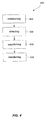
- a method for improving audio experience for a user of an audio device comprising: establishing 602 a communication channel between the audio device and a remote client; detecting 604 a peripheral audio device in the vicinity of the audio device; establishing 606 a temporary communication channel between the peripheral audio device and the remote client; transferring 608, via the temporary communication channel, audio data between the peripheral audio device and the remote client.
- data may be transmitted over a fixed line such as a telephone line, such that a communication channel between the audio device and the remote client is established.
- a fixed line such as a telephone line
- a communication channel between the audio device and the remote client is established.
- other means for transmission of data may be used such that the communication channel is established between the audio device and the remote client.
- the peripheral device may be any personal digital device capable of communicating with the audio device, e.g., a cell phone, a personal digital assistant, a computer, a tablet computer, or a headset for any of these.
- the temporary communication channel and/or the communication channel may use encryption when sending data comprising sensitive information such as a telephone number.
Landscapes
- Engineering & Computer Science (AREA)
- Signal Processing (AREA)
- Computer Networks & Wireless Communication (AREA)
- Business, Economics & Management (AREA)
- General Business, Economics & Management (AREA)
- Multimedia (AREA)
- Physics & Mathematics (AREA)
- Acoustics & Sound (AREA)
- Telephonic Communication Services (AREA)
- Telephone Function (AREA)
Priority Applications (6)
| Application Number | Priority Date | Filing Date | Title |
|---|---|---|---|
| EP14196430.4A EP3029964B1 (en) | 2014-12-05 | 2014-12-05 | Method for improving audio experience for a user of an audio device |
| TW104136902A TWI617974B (zh) | 2014-12-05 | 2015-11-09 | 用於改善一音訊裝置之一使用者之音訊體驗之方法 |
| US14/938,397 US9961459B2 (en) | 2014-12-05 | 2015-11-11 | Method for improving audio experience for a user of an audio device |
| KR1020150159591A KR101716833B1 (ko) | 2014-12-05 | 2015-11-13 | 오디오 디바이스의 사용자를 위해 오디오 경험을 개선시키는 방법 |
| JP2015228434A JP6228585B2 (ja) | 2014-12-05 | 2015-11-24 | 音声機器のユーザにとっての音声体感を改善する方法 |
| CN201510856178.0A CN105682004B (zh) | 2014-12-05 | 2015-11-30 | 用于改善音频装置的用户的音频体验的方法 |
Applications Claiming Priority (1)
| Application Number | Priority Date | Filing Date | Title |
|---|---|---|---|
| EP14196430.4A EP3029964B1 (en) | 2014-12-05 | 2014-12-05 | Method for improving audio experience for a user of an audio device |
Publications (2)
| Publication Number | Publication Date |
|---|---|
| EP3029964A1 EP3029964A1 (en) | 2016-06-08 |
| EP3029964B1 true EP3029964B1 (en) | 2016-09-28 |
Family
ID=52013901
Family Applications (1)
| Application Number | Title | Priority Date | Filing Date |
|---|---|---|---|
| EP14196430.4A Active EP3029964B1 (en) | 2014-12-05 | 2014-12-05 | Method for improving audio experience for a user of an audio device |
Country Status (6)
| Country | Link |
|---|---|
| US (1) | US9961459B2 (enExample) |
| EP (1) | EP3029964B1 (enExample) |
| JP (1) | JP6228585B2 (enExample) |
| KR (1) | KR101716833B1 (enExample) |
| CN (1) | CN105682004B (enExample) |
| TW (1) | TWI617974B (enExample) |
Families Citing this family (2)
| Publication number | Priority date | Publication date | Assignee | Title |
|---|---|---|---|---|
| US10948584B2 (en) * | 2017-03-15 | 2021-03-16 | The Regents Of The University Of Michigan | Latent oscillator frequency estimation for ranging measurements |
| US11264019B2 (en) * | 2017-06-30 | 2022-03-01 | Google Llc | Methods, systems, and media for voice-based call operations |
Family Cites Families (15)
| Publication number | Priority date | Publication date | Assignee | Title |
|---|---|---|---|---|
| US6999769B1 (en) * | 1999-12-08 | 2006-02-14 | Koninklijke Philips Electronics N.V. | Method for in-progress telephone call transfer between a wireless telephone and a wired telephone using a short-range communication control link |
| CA2434552A1 (en) * | 2001-01-18 | 2002-07-25 | C3Gateways Services Inc. | Network-assisted communication method and system therefor |
| US20030013503A1 (en) * | 2001-07-16 | 2003-01-16 | Royal Thoughts, L.L.C. | Intercom module for a wireless system |
| EP1509018A1 (de) * | 2003-08-18 | 2005-02-23 | Siemens Aktiengesellschaft | Verfahren, Software-Produkt und Vorrichtungen zur Signalisierung der Modifikation von Bearerverbindungen mittels SIP Protokoll |
| KR20050043597A (ko) * | 2003-11-04 | 2005-05-11 | 한국전자통신연구원 | 인터넷을 이용한 홈 방문자 확인 서비스 방법 |
| GB2452020A (en) * | 2007-07-20 | 2009-02-25 | Nec Technologies | Communication establishment methodand related communication devices |
| US8363868B2 (en) * | 2008-04-09 | 2013-01-29 | Panasonic Corporation | Hearing aid, hearing-aid apparatus, hearing-aid method and integrated circuit thereof |
| JP2010232993A (ja) * | 2009-03-27 | 2010-10-14 | Aiphone Co Ltd | ハンズフリーインターホン装置 |
| CN101925053B (zh) * | 2009-06-12 | 2013-04-03 | 中国移动通信集团公司 | 一种ims域的会话控制的方法、系统及服务器 |
| JP2011097381A (ja) * | 2009-10-30 | 2011-05-12 | Aiphone Co Ltd | インターホンシステム |
| US20130205191A1 (en) | 2012-02-08 | 2013-08-08 | Honeywell International Inc. | Systems and methods of electronic visitor registration |
| US9363653B2 (en) * | 2012-03-08 | 2016-06-07 | Intel Corporation | Transfer of communication from one device to another |
| JP2014090380A (ja) * | 2012-10-31 | 2014-05-15 | Toshiba Corp | 無線通信装置、無線通信システム及び無線通信方法 |
| US9277402B2 (en) * | 2013-03-06 | 2016-03-01 | Qualcomm Incorporated | Systems and methods for secure high-speed link maintenance via NFC |
| JP6107261B2 (ja) * | 2013-03-15 | 2017-04-05 | ブラザー工業株式会社 | 中継装置、画像処理装置および通信システム |
-
2014
- 2014-12-05 EP EP14196430.4A patent/EP3029964B1/en active Active
-
2015
- 2015-11-09 TW TW104136902A patent/TWI617974B/zh active
- 2015-11-11 US US14/938,397 patent/US9961459B2/en active Active
- 2015-11-13 KR KR1020150159591A patent/KR101716833B1/ko active Active
- 2015-11-24 JP JP2015228434A patent/JP6228585B2/ja active Active
- 2015-11-30 CN CN201510856178.0A patent/CN105682004B/zh active Active
Non-Patent Citations (1)
| Title |
|---|
| None * |
Also Published As
| Publication number | Publication date |
|---|---|
| JP2016146617A (ja) | 2016-08-12 |
| JP6228585B2 (ja) | 2017-11-08 |
| CN105682004A (zh) | 2016-06-15 |
| KR101716833B1 (ko) | 2017-03-15 |
| TW201629751A (zh) | 2016-08-16 |
| US9961459B2 (en) | 2018-05-01 |
| CN105682004B (zh) | 2017-06-09 |
| US20160165370A1 (en) | 2016-06-09 |
| KR20160068653A (ko) | 2016-06-15 |
| EP3029964A1 (en) | 2016-06-08 |
| TWI617974B (zh) | 2018-03-11 |
Similar Documents
| Publication | Publication Date | Title |
|---|---|---|
| US9621603B2 (en) | Method for pairing a computer with a video conference device | |
| US20180124527A1 (en) | Hearing assistance method utilizing a broadcast audio stream | |
| US20110319018A1 (en) | Method for establishing short-range, wireless communication between a mobile phone and a hearing aid | |
| WO2020163722A1 (en) | Assistive listening device systems, devices and methods for providing audio streams within sound fields | |
| CN104025559A (zh) | 在综合分布网络中传输音频路由 | |
| CN103023866A (zh) | 无线音频信号的易共享 | |
| US10827455B1 (en) | Method and apparatus for sending a notification to a short-range wireless communication audio output device | |
| CN109076561A (zh) | 资源配置方法及装置 | |
| US11026277B2 (en) | Assistive listening system that uses sound waves for device pairing | |
| US20100318656A1 (en) | Multiple-channel, short-range networking between wireless devices | |
| EP3029964B1 (en) | Method for improving audio experience for a user of an audio device | |
| CN103167382A (zh) | 用于听力装置的可配置fm接收器 | |
| US8190095B1 (en) | RF audio distribution system including IR presence detection | |
| CN105592395B (zh) | 用于音频设备的音频校准的方法和系统 | |
| KR101649171B1 (ko) | 복수의 스피커를 제어하는 원격제어장치 | |
| US20080089513A1 (en) | Methods and devices for detection, control and annunciation of speakerphone use | |
| US20200396540A1 (en) | Audio/visual device with central control, assistive listening, or a screen | |
| US20200235825A1 (en) | Panic alerts using ultrasonic sound waves | |
| EP3160107B1 (en) | Intercom system, server apparatus, and communication method | |
| US7692681B2 (en) | Image and audio controls for a communication device in push-to-video services | |
| WO2012174676A1 (en) | An intelligent monitoring system using the mobile communication network | |
| KR20190047559A (ko) | 블루투스 이어폰 장치를 이용한 오티피 제공 시스템 및 방법 | |
| US20160006812A1 (en) | Robust Communication Protocol, Pairing Procedure and Emergency Messaging System For a Server Computer And at Least Two Client Computers | |
| US10348416B2 (en) | Acoustic information transfer | |
| EP4358563A1 (en) | Method and system for transmitting audio signals |
Legal Events
| Date | Code | Title | Description |
|---|---|---|---|
| PUAI | Public reference made under article 153(3) epc to a published international application that has entered the european phase |
Free format text: ORIGINAL CODE: 0009012 |
|
| 17P | Request for examination filed |
Effective date: 20150703 |
|
| AK | Designated contracting states |
Kind code of ref document: A1 Designated state(s): AL AT BE BG CH CY CZ DE DK EE ES FI FR GB GR HR HU IE IS IT LI LT LU LV MC MK MT NL NO PL PT RO RS SE SI SK SM TR |
|
| AX | Request for extension of the european patent |
Extension state: BA ME |
|
| REG | Reference to a national code |
Ref country code: DE Ref legal event code: R079 Ref document number: 602014003968 Country of ref document: DE Free format text: PREVIOUS MAIN CLASS: H04W0004200000 Ipc: H04L0029060000 |
|
| GRAP | Despatch of communication of intention to grant a patent |
Free format text: ORIGINAL CODE: EPIDOSNIGR1 |
|
| RIC1 | Information provided on ipc code assigned before grant |
Ipc: H04W 4/00 20090101ALI20160623BHEP Ipc: H04L 29/06 20060101AFI20160623BHEP Ipc: H04W 4/20 20090101ALI20160623BHEP Ipc: H04W 4/16 20090101ALI20160623BHEP |
|
| INTG | Intention to grant announced |
Effective date: 20160707 |
|
| GRAS | Grant fee paid |
Free format text: ORIGINAL CODE: EPIDOSNIGR3 |
|
| GRAA | (expected) grant |
Free format text: ORIGINAL CODE: 0009210 |
|
| AK | Designated contracting states |
Kind code of ref document: B1 Designated state(s): AL AT BE BG CH CY CZ DE DK EE ES FI FR GB GR HR HU IE IS IT LI LT LU LV MC MK MT NL NO PL PT RO RS SE SI SK SM TR |
|
| REG | Reference to a national code |
Ref country code: GB Ref legal event code: FG4D |
|
| REG | Reference to a national code |
Ref country code: CH Ref legal event code: EP |
|
| REG | Reference to a national code |
Ref country code: AT Ref legal event code: REF Ref document number: 833599 Country of ref document: AT Kind code of ref document: T Effective date: 20161015 |
|
| REG | Reference to a national code |
Ref country code: IE Ref legal event code: FG4D |
|
| REG | Reference to a national code |
Ref country code: SE Ref legal event code: TRGR |
|
| REG | Reference to a national code |
Ref country code: DE Ref legal event code: R096 Ref document number: 602014003968 Country of ref document: DE |
|
| REG | Reference to a national code |
Ref country code: FR Ref legal event code: PLFP Year of fee payment: 3 |
|
| REG | Reference to a national code |
Ref country code: LT Ref legal event code: MG4D |
|
| PG25 | Lapsed in a contracting state [announced via postgrant information from national office to epo] |
Ref country code: NO Free format text: LAPSE BECAUSE OF FAILURE TO SUBMIT A TRANSLATION OF THE DESCRIPTION OR TO PAY THE FEE WITHIN THE PRESCRIBED TIME-LIMIT Effective date: 20161228 Ref country code: LT Free format text: LAPSE BECAUSE OF FAILURE TO SUBMIT A TRANSLATION OF THE DESCRIPTION OR TO PAY THE FEE WITHIN THE PRESCRIBED TIME-LIMIT Effective date: 20160928 Ref country code: FI Free format text: LAPSE BECAUSE OF FAILURE TO SUBMIT A TRANSLATION OF THE DESCRIPTION OR TO PAY THE FEE WITHIN THE PRESCRIBED TIME-LIMIT Effective date: 20160928 Ref country code: RS Free format text: LAPSE BECAUSE OF FAILURE TO SUBMIT A TRANSLATION OF THE DESCRIPTION OR TO PAY THE FEE WITHIN THE PRESCRIBED TIME-LIMIT Effective date: 20160928 Ref country code: HR Free format text: LAPSE BECAUSE OF FAILURE TO SUBMIT A TRANSLATION OF THE DESCRIPTION OR TO PAY THE FEE WITHIN THE PRESCRIBED TIME-LIMIT Effective date: 20160928 |
|
| REG | Reference to a national code |
Ref country code: NL Ref legal event code: MP Effective date: 20160928 |
|
| REG | Reference to a national code |
Ref country code: AT Ref legal event code: MK05 Ref document number: 833599 Country of ref document: AT Kind code of ref document: T Effective date: 20160928 |
|
| PG25 | Lapsed in a contracting state [announced via postgrant information from national office to epo] |
Ref country code: GR Free format text: LAPSE BECAUSE OF FAILURE TO SUBMIT A TRANSLATION OF THE DESCRIPTION OR TO PAY THE FEE WITHIN THE PRESCRIBED TIME-LIMIT Effective date: 20161229 Ref country code: LV Free format text: LAPSE BECAUSE OF FAILURE TO SUBMIT A TRANSLATION OF THE DESCRIPTION OR TO PAY THE FEE WITHIN THE PRESCRIBED TIME-LIMIT Effective date: 20160928 Ref country code: NL Free format text: LAPSE BECAUSE OF FAILURE TO SUBMIT A TRANSLATION OF THE DESCRIPTION OR TO PAY THE FEE WITHIN THE PRESCRIBED TIME-LIMIT Effective date: 20160928 |
|
| PG25 | Lapsed in a contracting state [announced via postgrant information from national office to epo] |
Ref country code: EE Free format text: LAPSE BECAUSE OF FAILURE TO SUBMIT A TRANSLATION OF THE DESCRIPTION OR TO PAY THE FEE WITHIN THE PRESCRIBED TIME-LIMIT Effective date: 20160928 Ref country code: RO Free format text: LAPSE BECAUSE OF FAILURE TO SUBMIT A TRANSLATION OF THE DESCRIPTION OR TO PAY THE FEE WITHIN THE PRESCRIBED TIME-LIMIT Effective date: 20160928 |
|
| PG25 | Lapsed in a contracting state [announced via postgrant information from national office to epo] |
Ref country code: BG Free format text: LAPSE BECAUSE OF FAILURE TO SUBMIT A TRANSLATION OF THE DESCRIPTION OR TO PAY THE FEE WITHIN THE PRESCRIBED TIME-LIMIT Effective date: 20161228 Ref country code: PL Free format text: LAPSE BECAUSE OF FAILURE TO SUBMIT A TRANSLATION OF THE DESCRIPTION OR TO PAY THE FEE WITHIN THE PRESCRIBED TIME-LIMIT Effective date: 20160928 Ref country code: SK Free format text: LAPSE BECAUSE OF FAILURE TO SUBMIT A TRANSLATION OF THE DESCRIPTION OR TO PAY THE FEE WITHIN THE PRESCRIBED TIME-LIMIT Effective date: 20160928 Ref country code: BE Free format text: LAPSE BECAUSE OF FAILURE TO SUBMIT A TRANSLATION OF THE DESCRIPTION OR TO PAY THE FEE WITHIN THE PRESCRIBED TIME-LIMIT Effective date: 20160928 Ref country code: AT Free format text: LAPSE BECAUSE OF FAILURE TO SUBMIT A TRANSLATION OF THE DESCRIPTION OR TO PAY THE FEE WITHIN THE PRESCRIBED TIME-LIMIT Effective date: 20160928 Ref country code: CZ Free format text: LAPSE BECAUSE OF FAILURE TO SUBMIT A TRANSLATION OF THE DESCRIPTION OR TO PAY THE FEE WITHIN THE PRESCRIBED TIME-LIMIT Effective date: 20160928 Ref country code: ES Free format text: LAPSE BECAUSE OF FAILURE TO SUBMIT A TRANSLATION OF THE DESCRIPTION OR TO PAY THE FEE WITHIN THE PRESCRIBED TIME-LIMIT Effective date: 20160928 Ref country code: PT Free format text: LAPSE BECAUSE OF FAILURE TO SUBMIT A TRANSLATION OF THE DESCRIPTION OR TO PAY THE FEE WITHIN THE PRESCRIBED TIME-LIMIT Effective date: 20170130 Ref country code: SM Free format text: LAPSE BECAUSE OF FAILURE TO SUBMIT A TRANSLATION OF THE DESCRIPTION OR TO PAY THE FEE WITHIN THE PRESCRIBED TIME-LIMIT Effective date: 20160928 Ref country code: IS Free format text: LAPSE BECAUSE OF FAILURE TO SUBMIT A TRANSLATION OF THE DESCRIPTION OR TO PAY THE FEE WITHIN THE PRESCRIBED TIME-LIMIT Effective date: 20170128 |
|
| REG | Reference to a national code |
Ref country code: DE Ref legal event code: R097 Ref document number: 602014003968 Country of ref document: DE |
|
| PG25 | Lapsed in a contracting state [announced via postgrant information from national office to epo] |
Ref country code: IT Free format text: LAPSE BECAUSE OF FAILURE TO SUBMIT A TRANSLATION OF THE DESCRIPTION OR TO PAY THE FEE WITHIN THE PRESCRIBED TIME-LIMIT Effective date: 20160928 |
|
| PG25 | Lapsed in a contracting state [announced via postgrant information from national office to epo] |
Ref country code: DK Free format text: LAPSE BECAUSE OF FAILURE TO SUBMIT A TRANSLATION OF THE DESCRIPTION OR TO PAY THE FEE WITHIN THE PRESCRIBED TIME-LIMIT Effective date: 20160928 |
|
| PLBE | No opposition filed within time limit |
Free format text: ORIGINAL CODE: 0009261 |
|
| STAA | Information on the status of an ep patent application or granted ep patent |
Free format text: STATUS: NO OPPOSITION FILED WITHIN TIME LIMIT |
|
| 26N | No opposition filed |
Effective date: 20170629 |
|
| PG25 | Lapsed in a contracting state [announced via postgrant information from national office to epo] |
Ref country code: MC Free format text: LAPSE BECAUSE OF FAILURE TO SUBMIT A TRANSLATION OF THE DESCRIPTION OR TO PAY THE FEE WITHIN THE PRESCRIBED TIME-LIMIT Effective date: 20160928 |
|
| REG | Reference to a national code |
Ref country code: IE Ref legal event code: MM4A |
|
| PG25 | Lapsed in a contracting state [announced via postgrant information from national office to epo] |
Ref country code: LU Free format text: LAPSE BECAUSE OF NON-PAYMENT OF DUE FEES Effective date: 20161205 |
|
| REG | Reference to a national code |
Ref country code: FR Ref legal event code: PLFP Year of fee payment: 4 |
|
| PG25 | Lapsed in a contracting state [announced via postgrant information from national office to epo] |
Ref country code: IE Free format text: LAPSE BECAUSE OF NON-PAYMENT OF DUE FEES Effective date: 20161205 Ref country code: SI Free format text: LAPSE BECAUSE OF FAILURE TO SUBMIT A TRANSLATION OF THE DESCRIPTION OR TO PAY THE FEE WITHIN THE PRESCRIBED TIME-LIMIT Effective date: 20160928 |
|
| PG25 | Lapsed in a contracting state [announced via postgrant information from national office to epo] |
Ref country code: HU Free format text: LAPSE BECAUSE OF FAILURE TO SUBMIT A TRANSLATION OF THE DESCRIPTION OR TO PAY THE FEE WITHIN THE PRESCRIBED TIME-LIMIT; INVALID AB INITIO Effective date: 20141205 |
|
| PG25 | Lapsed in a contracting state [announced via postgrant information from national office to epo] |
Ref country code: CY Free format text: LAPSE BECAUSE OF FAILURE TO SUBMIT A TRANSLATION OF THE DESCRIPTION OR TO PAY THE FEE WITHIN THE PRESCRIBED TIME-LIMIT Effective date: 20160928 Ref country code: MK Free format text: LAPSE BECAUSE OF FAILURE TO SUBMIT A TRANSLATION OF THE DESCRIPTION OR TO PAY THE FEE WITHIN THE PRESCRIBED TIME-LIMIT Effective date: 20160928 |
|
| REG | Reference to a national code |
Ref country code: CH Ref legal event code: PL |
|
| PG25 | Lapsed in a contracting state [announced via postgrant information from national office to epo] |
Ref country code: MT Free format text: LAPSE BECAUSE OF NON-PAYMENT OF DUE FEES Effective date: 20161205 |
|
| PG25 | Lapsed in a contracting state [announced via postgrant information from national office to epo] |
Ref country code: AL Free format text: LAPSE BECAUSE OF FAILURE TO SUBMIT A TRANSLATION OF THE DESCRIPTION OR TO PAY THE FEE WITHIN THE PRESCRIBED TIME-LIMIT Effective date: 20160928 Ref country code: TR Free format text: LAPSE BECAUSE OF FAILURE TO SUBMIT A TRANSLATION OF THE DESCRIPTION OR TO PAY THE FEE WITHIN THE PRESCRIBED TIME-LIMIT Effective date: 20160928 |
|
| PG25 | Lapsed in a contracting state [announced via postgrant information from national office to epo] |
Ref country code: CH Free format text: LAPSE BECAUSE OF NON-PAYMENT OF DUE FEES Effective date: 20171231 Ref country code: LI Free format text: LAPSE BECAUSE OF NON-PAYMENT OF DUE FEES Effective date: 20171231 |
|
| REG | Reference to a national code |
Ref country code: DE Ref legal event code: R079 Ref document number: 602014003968 Country of ref document: DE Free format text: PREVIOUS MAIN CLASS: H04L0029060000 Ipc: H04L0065000000 |
|
| P01 | Opt-out of the competence of the unified patent court (upc) registered |
Effective date: 20230505 |
|
| PGFP | Annual fee paid to national office [announced via postgrant information from national office to epo] |
Ref country code: DE Payment date: 20241121 Year of fee payment: 11 |
|
| PGFP | Annual fee paid to national office [announced via postgrant information from national office to epo] |
Ref country code: GB Payment date: 20241122 Year of fee payment: 11 |
|
| PGFP | Annual fee paid to national office [announced via postgrant information from national office to epo] |
Ref country code: FR Payment date: 20241121 Year of fee payment: 11 |
|
| PGFP | Annual fee paid to national office [announced via postgrant information from national office to epo] |
Ref country code: SE Payment date: 20241121 Year of fee payment: 11 |