EP3029339B1 - Verbindung und luftfahrzeugstruktur - Google Patents
Verbindung und luftfahrzeugstruktur Download PDFInfo
- Publication number
- EP3029339B1 EP3029339B1 EP14851251.0A EP14851251A EP3029339B1 EP 3029339 B1 EP3029339 B1 EP 3029339B1 EP 14851251 A EP14851251 A EP 14851251A EP 3029339 B1 EP3029339 B1 EP 3029339B1
- Authority
- EP
- European Patent Office
- Prior art keywords
- joint
- preform
- strength
- plane direction
- present
- Prior art date
- Legal status (The legal status is an assumption and is not a legal conclusion. Google has not performed a legal analysis and makes no representation as to the accuracy of the status listed.)
- Active
Links
Images





Classifications
-
- B—PERFORMING OPERATIONS; TRANSPORTING
- B29—WORKING OF PLASTICS; WORKING OF SUBSTANCES IN A PLASTIC STATE IN GENERAL
- B29C—SHAPING OR JOINING OF PLASTICS; SHAPING OF MATERIAL IN A PLASTIC STATE, NOT OTHERWISE PROVIDED FOR; AFTER-TREATMENT OF THE SHAPED PRODUCTS, e.g. REPAIRING
- B29C65/00—Joining or sealing of preformed parts, e.g. welding of plastics materials; Apparatus therefor
- B29C65/48—Joining or sealing of preformed parts, e.g. welding of plastics materials; Apparatus therefor using adhesives, i.e. using supplementary joining material; solvent bonding
- B29C65/50—Joining or sealing of preformed parts, e.g. welding of plastics materials; Apparatus therefor using adhesives, i.e. using supplementary joining material; solvent bonding using adhesive tape, e.g. thermoplastic tape; using threads or the like
- B29C65/5057—Joining or sealing of preformed parts, e.g. welding of plastics materials; Apparatus therefor using adhesives, i.e. using supplementary joining material; solvent bonding using adhesive tape, e.g. thermoplastic tape; using threads or the like positioned between the surfaces to be joined
-
- B—PERFORMING OPERATIONS; TRANSPORTING
- B29—WORKING OF PLASTICS; WORKING OF SUBSTANCES IN A PLASTIC STATE IN GENERAL
- B29C—SHAPING OR JOINING OF PLASTICS; SHAPING OF MATERIAL IN A PLASTIC STATE, NOT OTHERWISE PROVIDED FOR; AFTER-TREATMENT OF THE SHAPED PRODUCTS, e.g. REPAIRING
- B29C65/00—Joining or sealing of preformed parts, e.g. welding of plastics materials; Apparatus therefor
- B29C65/48—Joining or sealing of preformed parts, e.g. welding of plastics materials; Apparatus therefor using adhesives, i.e. using supplementary joining material; solvent bonding
- B29C65/50—Joining or sealing of preformed parts, e.g. welding of plastics materials; Apparatus therefor using adhesives, i.e. using supplementary joining material; solvent bonding using adhesive tape, e.g. thermoplastic tape; using threads or the like
- B29C65/5064—Joining or sealing of preformed parts, e.g. welding of plastics materials; Apparatus therefor using adhesives, i.e. using supplementary joining material; solvent bonding using adhesive tape, e.g. thermoplastic tape; using threads or the like of particular form, e.g. being C-shaped, T-shaped
- B29C65/5071—Joining or sealing of preformed parts, e.g. welding of plastics materials; Apparatus therefor using adhesives, i.e. using supplementary joining material; solvent bonding using adhesive tape, e.g. thermoplastic tape; using threads or the like of particular form, e.g. being C-shaped, T-shaped and being composed by one single element
-
- B—PERFORMING OPERATIONS; TRANSPORTING
- B29—WORKING OF PLASTICS; WORKING OF SUBSTANCES IN A PLASTIC STATE IN GENERAL
- B29C—SHAPING OR JOINING OF PLASTICS; SHAPING OF MATERIAL IN A PLASTIC STATE, NOT OTHERWISE PROVIDED FOR; AFTER-TREATMENT OF THE SHAPED PRODUCTS, e.g. REPAIRING
- B29C65/00—Joining or sealing of preformed parts, e.g. welding of plastics materials; Apparatus therefor
- B29C65/48—Joining or sealing of preformed parts, e.g. welding of plastics materials; Apparatus therefor using adhesives, i.e. using supplementary joining material; solvent bonding
- B29C65/50—Joining or sealing of preformed parts, e.g. welding of plastics materials; Apparatus therefor using adhesives, i.e. using supplementary joining material; solvent bonding using adhesive tape, e.g. thermoplastic tape; using threads or the like
- B29C65/5064—Joining or sealing of preformed parts, e.g. welding of plastics materials; Apparatus therefor using adhesives, i.e. using supplementary joining material; solvent bonding using adhesive tape, e.g. thermoplastic tape; using threads or the like of particular form, e.g. being C-shaped, T-shaped
- B29C65/5085—Joining or sealing of preformed parts, e.g. welding of plastics materials; Apparatus therefor using adhesives, i.e. using supplementary joining material; solvent bonding using adhesive tape, e.g. thermoplastic tape; using threads or the like of particular form, e.g. being C-shaped, T-shaped and comprising grooves, e.g. being E-shaped, H-shaped
-
- B—PERFORMING OPERATIONS; TRANSPORTING
- B29—WORKING OF PLASTICS; WORKING OF SUBSTANCES IN A PLASTIC STATE IN GENERAL
- B29C—SHAPING OR JOINING OF PLASTICS; SHAPING OF MATERIAL IN A PLASTIC STATE, NOT OTHERWISE PROVIDED FOR; AFTER-TREATMENT OF THE SHAPED PRODUCTS, e.g. REPAIRING
- B29C66/00—General aspects of processes or apparatus for joining preformed parts
- B29C66/01—General aspects dealing with the joint area or with the area to be joined
- B29C66/05—Particular design of joint configurations
- B29C66/10—Particular design of joint configurations particular design of the joint cross-sections
- B29C66/11—Joint cross-sections comprising a single joint-segment, i.e. one of the parts to be joined comprising a single joint-segment in the joint cross-section
- B29C66/112—Single lapped joints
-
- B—PERFORMING OPERATIONS; TRANSPORTING
- B29—WORKING OF PLASTICS; WORKING OF SUBSTANCES IN A PLASTIC STATE IN GENERAL
- B29C—SHAPING OR JOINING OF PLASTICS; SHAPING OF MATERIAL IN A PLASTIC STATE, NOT OTHERWISE PROVIDED FOR; AFTER-TREATMENT OF THE SHAPED PRODUCTS, e.g. REPAIRING
- B29C66/00—General aspects of processes or apparatus for joining preformed parts
- B29C66/01—General aspects dealing with the joint area or with the area to be joined
- B29C66/05—Particular design of joint configurations
- B29C66/10—Particular design of joint configurations particular design of the joint cross-sections
- B29C66/11—Joint cross-sections comprising a single joint-segment, i.e. one of the parts to be joined comprising a single joint-segment in the joint cross-section
- B29C66/114—Single butt joints
-
- B—PERFORMING OPERATIONS; TRANSPORTING
- B29—WORKING OF PLASTICS; WORKING OF SUBSTANCES IN A PLASTIC STATE IN GENERAL
- B29C—SHAPING OR JOINING OF PLASTICS; SHAPING OF MATERIAL IN A PLASTIC STATE, NOT OTHERWISE PROVIDED FOR; AFTER-TREATMENT OF THE SHAPED PRODUCTS, e.g. REPAIRING
- B29C66/00—General aspects of processes or apparatus for joining preformed parts
- B29C66/01—General aspects dealing with the joint area or with the area to be joined
- B29C66/05—Particular design of joint configurations
- B29C66/10—Particular design of joint configurations particular design of the joint cross-sections
- B29C66/12—Joint cross-sections combining only two joint-segments; Tongue and groove joints; Tenon and mortise joints; Stepped joint cross-sections
- B29C66/124—Tongue and groove joints
- B29C66/1244—Tongue and groove joints characterised by the male part, i.e. the part comprising the tongue
- B29C66/12443—Tongue and groove joints characterised by the male part, i.e. the part comprising the tongue having the tongue substantially in the middle
-
- B—PERFORMING OPERATIONS; TRANSPORTING
- B29—WORKING OF PLASTICS; WORKING OF SUBSTANCES IN A PLASTIC STATE IN GENERAL
- B29C—SHAPING OR JOINING OF PLASTICS; SHAPING OF MATERIAL IN A PLASTIC STATE, NOT OTHERWISE PROVIDED FOR; AFTER-TREATMENT OF THE SHAPED PRODUCTS, e.g. REPAIRING
- B29C66/00—General aspects of processes or apparatus for joining preformed parts
- B29C66/01—General aspects dealing with the joint area or with the area to be joined
- B29C66/05—Particular design of joint configurations
- B29C66/10—Particular design of joint configurations particular design of the joint cross-sections
- B29C66/12—Joint cross-sections combining only two joint-segments; Tongue and groove joints; Tenon and mortise joints; Stepped joint cross-sections
- B29C66/124—Tongue and groove joints
- B29C66/1246—Tongue and groove joints characterised by the female part, i.e. the part comprising the groove
- B29C66/12463—Tongue and groove joints characterised by the female part, i.e. the part comprising the groove being tapered
- B29C66/12464—Tongue and groove joints characterised by the female part, i.e. the part comprising the groove being tapered being V-shaped
-
- B—PERFORMING OPERATIONS; TRANSPORTING
- B29—WORKING OF PLASTICS; WORKING OF SUBSTANCES IN A PLASTIC STATE IN GENERAL
- B29C—SHAPING OR JOINING OF PLASTICS; SHAPING OF MATERIAL IN A PLASTIC STATE, NOT OTHERWISE PROVIDED FOR; AFTER-TREATMENT OF THE SHAPED PRODUCTS, e.g. REPAIRING
- B29C66/00—General aspects of processes or apparatus for joining preformed parts
- B29C66/01—General aspects dealing with the joint area or with the area to be joined
- B29C66/05—Particular design of joint configurations
- B29C66/10—Particular design of joint configurations particular design of the joint cross-sections
- B29C66/13—Single flanged joints; Fin-type joints; Single hem joints; Edge joints; Interpenetrating fingered joints; Other specific particular designs of joint cross-sections not provided for in groups B29C66/11 - B29C66/12
- B29C66/131—Single flanged joints, i.e. one of the parts to be joined being rigid and flanged in the joint area
-
- B—PERFORMING OPERATIONS; TRANSPORTING
- B29—WORKING OF PLASTICS; WORKING OF SUBSTANCES IN A PLASTIC STATE IN GENERAL
- B29C—SHAPING OR JOINING OF PLASTICS; SHAPING OF MATERIAL IN A PLASTIC STATE, NOT OTHERWISE PROVIDED FOR; AFTER-TREATMENT OF THE SHAPED PRODUCTS, e.g. REPAIRING
- B29C66/00—General aspects of processes or apparatus for joining preformed parts
- B29C66/01—General aspects dealing with the joint area or with the area to be joined
- B29C66/05—Particular design of joint configurations
- B29C66/301—Three-dimensional joints, i.e. the joined area being substantially non-flat
-
- B—PERFORMING OPERATIONS; TRANSPORTING
- B29—WORKING OF PLASTICS; WORKING OF SUBSTANCES IN A PLASTIC STATE IN GENERAL
- B29C—SHAPING OR JOINING OF PLASTICS; SHAPING OF MATERIAL IN A PLASTIC STATE, NOT OTHERWISE PROVIDED FOR; AFTER-TREATMENT OF THE SHAPED PRODUCTS, e.g. REPAIRING
- B29C66/00—General aspects of processes or apparatus for joining preformed parts
- B29C66/40—General aspects of joining substantially flat articles, e.g. plates, sheets or web-like materials; Making flat seams in tubular or hollow articles; Joining single elements to substantially flat surfaces
- B29C66/41—Joining substantially flat articles ; Making flat seams in tubular or hollow articles
- B29C66/43—Joining a relatively small portion of the surface of said articles
- B29C66/434—Joining substantially flat articles for forming corner connections, fork connections or cross connections
- B29C66/4344—Joining substantially flat articles for forming fork connections, e.g. for making Y-shaped pieces
- B29C66/43441—Joining substantially flat articles for forming fork connections, e.g. for making Y-shaped pieces with two right angles, e.g. for making T-shaped pieces, H-shaped pieces
-
- B—PERFORMING OPERATIONS; TRANSPORTING
- B29—WORKING OF PLASTICS; WORKING OF SUBSTANCES IN A PLASTIC STATE IN GENERAL
- B29C—SHAPING OR JOINING OF PLASTICS; SHAPING OF MATERIAL IN A PLASTIC STATE, NOT OTHERWISE PROVIDED FOR; AFTER-TREATMENT OF THE SHAPED PRODUCTS, e.g. REPAIRING
- B29C66/00—General aspects of processes or apparatus for joining preformed parts
- B29C66/50—General aspects of joining tubular articles; General aspects of joining long products, i.e. bars or profiled elements; General aspects of joining single elements to tubular articles, hollow articles or bars; General aspects of joining several hollow-preforms to form hollow or tubular articles
- B29C66/51—Joining tubular articles, profiled elements or bars; Joining single elements to tubular articles, hollow articles or bars; Joining several hollow-preforms to form hollow or tubular articles
- B29C66/52—Joining tubular articles, bars or profiled elements
- B29C66/524—Joining profiled elements
-
- B—PERFORMING OPERATIONS; TRANSPORTING
- B29—WORKING OF PLASTICS; WORKING OF SUBSTANCES IN A PLASTIC STATE IN GENERAL
- B29C—SHAPING OR JOINING OF PLASTICS; SHAPING OF MATERIAL IN A PLASTIC STATE, NOT OTHERWISE PROVIDED FOR; AFTER-TREATMENT OF THE SHAPED PRODUCTS, e.g. REPAIRING
- B29C66/00—General aspects of processes or apparatus for joining preformed parts
- B29C66/50—General aspects of joining tubular articles; General aspects of joining long products, i.e. bars or profiled elements; General aspects of joining single elements to tubular articles, hollow articles or bars; General aspects of joining several hollow-preforms to form hollow or tubular articles
- B29C66/51—Joining tubular articles, profiled elements or bars; Joining single elements to tubular articles, hollow articles or bars; Joining several hollow-preforms to form hollow or tubular articles
- B29C66/53—Joining single elements to tubular articles, hollow articles or bars
- B29C66/532—Joining single elements to the wall of tubular articles, hollow articles or bars
- B29C66/5326—Joining single elements to the wall of tubular articles, hollow articles or bars said single elements being substantially flat
-
- B—PERFORMING OPERATIONS; TRANSPORTING
- B29—WORKING OF PLASTICS; WORKING OF SUBSTANCES IN A PLASTIC STATE IN GENERAL
- B29C—SHAPING OR JOINING OF PLASTICS; SHAPING OF MATERIAL IN A PLASTIC STATE, NOT OTHERWISE PROVIDED FOR; AFTER-TREATMENT OF THE SHAPED PRODUCTS, e.g. REPAIRING
- B29C66/00—General aspects of processes or apparatus for joining preformed parts
- B29C66/70—General aspects of processes or apparatus for joining preformed parts characterised by the composition, physical properties or the structure of the material of the parts to be joined; Joining with non-plastics material
- B29C66/72—General aspects of processes or apparatus for joining preformed parts characterised by the composition, physical properties or the structure of the material of the parts to be joined; Joining with non-plastics material characterised by the structure of the material of the parts to be joined
- B29C66/721—Fibre-reinforced materials
-
- B—PERFORMING OPERATIONS; TRANSPORTING
- B64—AIRCRAFT; AVIATION; COSMONAUTICS
- B64C—AEROPLANES; HELICOPTERS
- B64C3/00—Wings
- B64C3/18—Spars; Ribs; Stringers
-
- F—MECHANICAL ENGINEERING; LIGHTING; HEATING; WEAPONS; BLASTING
- F16—ENGINEERING ELEMENTS AND UNITS; GENERAL MEASURES FOR PRODUCING AND MAINTAINING EFFECTIVE FUNCTIONING OF MACHINES OR INSTALLATIONS; THERMAL INSULATION IN GENERAL
- F16B—DEVICES FOR FASTENING OR SECURING CONSTRUCTIONAL ELEMENTS OR MACHINE PARTS TOGETHER, e.g. NAILS, BOLTS, CIRCLIPS, CLAMPS, CLIPS OR WEDGES; JOINTS OR JOINTING
- F16B11/00—Connecting constructional elements or machine parts by sticking or pressing them together, e.g. cold pressure welding
- F16B11/006—Connecting constructional elements or machine parts by sticking or pressing them together, e.g. cold pressure welding by gluing
-
- B—PERFORMING OPERATIONS; TRANSPORTING
- B29—WORKING OF PLASTICS; WORKING OF SUBSTANCES IN A PLASTIC STATE IN GENERAL
- B29C—SHAPING OR JOINING OF PLASTICS; SHAPING OF MATERIAL IN A PLASTIC STATE, NOT OTHERWISE PROVIDED FOR; AFTER-TREATMENT OF THE SHAPED PRODUCTS, e.g. REPAIRING
- B29C66/00—General aspects of processes or apparatus for joining preformed parts
- B29C66/01—General aspects dealing with the joint area or with the area to be joined
- B29C66/05—Particular design of joint configurations
- B29C66/10—Particular design of joint configurations particular design of the joint cross-sections
- B29C66/12—Joint cross-sections combining only two joint-segments; Tongue and groove joints; Tenon and mortise joints; Stepped joint cross-sections
- B29C66/124—Tongue and groove joints
- B29C66/1244—Tongue and groove joints characterised by the male part, i.e. the part comprising the tongue
- B29C66/12441—Tongue and groove joints characterised by the male part, i.e. the part comprising the tongue being a single wall
-
- B—PERFORMING OPERATIONS; TRANSPORTING
- B29—WORKING OF PLASTICS; WORKING OF SUBSTANCES IN A PLASTIC STATE IN GENERAL
- B29C—SHAPING OR JOINING OF PLASTICS; SHAPING OF MATERIAL IN A PLASTIC STATE, NOT OTHERWISE PROVIDED FOR; AFTER-TREATMENT OF THE SHAPED PRODUCTS, e.g. REPAIRING
- B29C66/00—General aspects of processes or apparatus for joining preformed parts
- B29C66/70—General aspects of processes or apparatus for joining preformed parts characterised by the composition, physical properties or the structure of the material of the parts to be joined; Joining with non-plastics material
- B29C66/72—General aspects of processes or apparatus for joining preformed parts characterised by the composition, physical properties or the structure of the material of the parts to be joined; Joining with non-plastics material characterised by the structure of the material of the parts to be joined
- B29C66/721—Fibre-reinforced materials
- B29C66/7212—Fibre-reinforced materials characterised by the composition of the fibres
-
- B—PERFORMING OPERATIONS; TRANSPORTING
- B29—WORKING OF PLASTICS; WORKING OF SUBSTANCES IN A PLASTIC STATE IN GENERAL
- B29L—INDEXING SCHEME ASSOCIATED WITH SUBCLASS B29C, RELATING TO PARTICULAR ARTICLES
- B29L2031/00—Other particular articles
- B29L2031/30—Vehicles, e.g. ships or aircraft, or body parts thereof
- B29L2031/3076—Aircrafts
-
- B—PERFORMING OPERATIONS; TRANSPORTING
- B64—AIRCRAFT; AVIATION; COSMONAUTICS
- B64C—AEROPLANES; HELICOPTERS
- B64C1/00—Fuselages; Constructional features common to fuselages, wings, stabilising surfaces or the like
-
- B—PERFORMING OPERATIONS; TRANSPORTING
- B64—AIRCRAFT; AVIATION; COSMONAUTICS
- B64C—AEROPLANES; HELICOPTERS
- B64C1/00—Fuselages; Constructional features common to fuselages, wings, stabilising surfaces or the like
- B64C1/06—Frames; Stringers; Longerons ; Fuselage sections
- B64C1/12—Construction or attachment of skin panels
-
- B—PERFORMING OPERATIONS; TRANSPORTING
- B64—AIRCRAFT; AVIATION; COSMONAUTICS
- B64C—AEROPLANES; HELICOPTERS
- B64C3/00—Wings
- B64C3/26—Construction, shape, or attachment of separate skins, e.g. panels
-
- B—PERFORMING OPERATIONS; TRANSPORTING
- B64—AIRCRAFT; AVIATION; COSMONAUTICS
- B64F—GROUND OR AIRCRAFT-CARRIER-DECK INSTALLATIONS SPECIALLY ADAPTED FOR USE IN CONNECTION WITH AIRCRAFT; DESIGNING, MANUFACTURING, ASSEMBLING, CLEANING, MAINTAINING OR REPAIRING AIRCRAFT, NOT OTHERWISE PROVIDED FOR; HANDLING, TRANSPORTING, TESTING OR INSPECTING AIRCRAFT COMPONENTS, NOT OTHERWISE PROVIDED FOR
- B64F5/00—Designing, manufacturing, assembling, cleaning, maintaining or repairing aircraft, not otherwise provided for; Handling, transporting, testing or inspecting aircraft components, not otherwise provided for
-
- F—MECHANICAL ENGINEERING; LIGHTING; HEATING; WEAPONS; BLASTING
- F16—ENGINEERING ELEMENTS AND UNITS; GENERAL MEASURES FOR PRODUCING AND MAINTAINING EFFECTIVE FUNCTIONING OF MACHINES OR INSTALLATIONS; THERMAL INSULATION IN GENERAL
- F16B—DEVICES FOR FASTENING OR SECURING CONSTRUCTIONAL ELEMENTS OR MACHINE PARTS TOGETHER, e.g. NAILS, BOLTS, CIRCLIPS, CLAMPS, CLIPS OR WEDGES; JOINTS OR JOINTING
- F16B11/00—Connecting constructional elements or machine parts by sticking or pressing them together, e.g. cold pressure welding
Definitions
- the present invention relates to an assembled structure with a joint, and an aircraft structure.
- CFRP carbon fiber reinforced plastics
- joints do not use fasteners, in order to achieve weight reduction of the structure.
- the members inserted into joints are bonded using adhesive, and the joints are also bonded to the preform using adhesive. In this way, members are jointed to the preform.
- plate members that are joined to the preform must be positioned with high accuracy. In other words, if the joint is provided in advance on the preform, it is necessary to position the plate member with respect to the joint with high accuracy.
- a peg (projection) for positioning is provided on a side face of a plate member, and a slot into which the peg is fitted is provided on a side face of a joint, and positioning is carried out by inserting the plate member so that the peg of the plate member is fitted into the slot of the joint.
- EP 1927732 A2 discloses a joint structure for connecting structures at mounting flanges.
- WO 02/16784 A2 discloses a structure for joining dissimilar materials to form a structural support member, wherein the joint has an inclined groove portion into which a member to be connected to a preform is inserted. The bonding surfaces between an expanded foot portion of the joint and the preform are flat and parallel.
- US 2008/0105661 A1 discloses a joint with a similar groove portion for receiving a member to be joined to a preform wherein the groove is inclined
- the bonding surface between the member and the preform is conventionally flat. However, when the bonding surface is flat, in some cases there is not sufficient strength with respect to loads in the out-of-plane direction.
- the assembled structure according to the present invention has the features of claim 1 and the aircraft structure according to the present invention utilizes the assembled structure of the invention.
- the assembled structure according to the present invention includes a joint that connects a member to a preform, wherein an inclined part, which is inclined relative to a surface that is orthogonal to the direction in which a tensile load is applied to the plate material, is formed on a bonding surface with the preform, and the inclined part is embedded in the preform and bonded to the preform.
- the joint according to this configuration joins the member to the preform.
- the joint according to this configuration is formed with an inclined part on the bonding surface with the preform.
- the inclined part is inclined with respect to a plane that is perpendicular to the direction in which a tensile load is applied to the member.
- the inclined part is inclined with respect to the preform.
- an indented part corresponding to the shape of the inclined part is formed on the preform so that the inclined part of the joint is embedded into a bonding surface with the joint. In this way, the joint 20 is bonded to the preform with the inclined part embedded in the preform.
- the bond strength includes an out-of-plane direction strength, which is the strength in the tensile direction of the member (the out-of-plane direction).
- the out-of-plane direction strength is the strength against tensile loads applied to the member (out-of-plane direction loads).
- the bond strength is divided into an in-plane direction strength, which is the strength in the shear direction of the bonding layer (the in-plane direction).
- the out-of-plane direction strength is perpendicular to the in-plane direction strength. Therefore, the theoretical bond strength with respect to out-of-plane direction loads is equal to the out-of-plane direction strength.
- the in-plane direction strength has a strength component in the out-of-plane direction. Therefore, the theoretical bond strength against out-of-plane direction loads includes the sine component of the in-plane direction bond strength in addition to the out-of-plane direction bond strength.
- the bond strength is greater when the inclined part is formed in the preform, compared with when the bonding surface is flat.
- the peak stress at the edge of the bonding surface is reduced compared with the case where the inclined part is not formed.
- the strength of the bonding surface between the joint and the preform can be increased.
- the surface opposite the bonding surface is inclined so that the thickness becomes smaller towards the edge than in the center.
- the difference in stiffness between the joint and the preform is reduced compared with the case in which the surface opposite the bonding surface is not inclined, in other words for example the edge of the joint is perpendicular to the preform.
- the edge of the joint is perpendicular to the preform.
- the inclined part is formed with a plurality of inclined surfaces.
- the bond strength of the bonding surface can be made uniform.
- the inclined part is formed with a plurality of inclined surfaces with different angles with respect to the preform.
- the strength of the bonding surface can be adjusted by changing the angle in accordance with the load expected to be applied to the joint.
- the aircraft structure according to the present invention includes the assembled structure as described above.
- the present invention has the advantageous effect that the strength of the bonding surface between the joint and the preform can be increased.
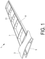
- FIG. 1 is a perspective view illustrating a partially sectioned main wing 1 of an aircraft.
- the main wing 1 includes an upper skin 3, a lower skin 5, a forward spar 7, a rear spar 9, and a plurality of ribs 11.
- the upper skin 3 and the lower skin 5 configure the outer shape of the main wing 1 and are thin plates also acting as aerodynamic surfaces. Along with the forward spar 7, the rear spar 9, and stringers (not illustrated), the upper skin 3 and the lower skin 5 partially bear tensile loads and compressive loads acting on the main wing 1.
- the forward spar 7 and the rear spar 9 are structural members that extend in the lengthwise direction of the main wing 1, and are disposed between the upper skin 3 and the lower skin 5.
- a plurality of stringers which are support members extending in the lengthwise direction of the main wing 1, is disposed on the inside face of the upper skin 3 or the lower skin 5, between the forward spar 7 and the rear spar 9.
- the ribs 11 are structural members extending in the widthwise direction of the main wing 1, and are disposed between the upper skin 3 and the lower skin 5.
- the ribs 11 are structural members extending in a direction roughly orthogonal to the forward spar 7 and the rear spar 9, and are plate-like members formed in the shape of the cross-sectional shape of the main wing 1.
- a joint 20 (see FIG. 2 and the like) of the assembled structure according to the present embodiment is used, for example, in the connection between the upper skin 3 and the forward spar 7 and the rear spar 9, the connection between the lower skin 5 and the forward spar 7 and the rear spar 9, the connection between the ribs 11 and the forward spar 7 and the rear spar 9, and the like.
- the joint 20 may be used in structures other than the main wing 1 of the aircraft.
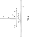
- FIG. 2 is a side view illustrating the shape of the joint 20 and a preform 22
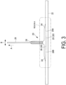
- FIG. 3 is a side view illustrating the joint 20 and the preform 22 connected
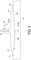
- FIG. 4 is an enlarged view of the region A illustrated in FIG. 3
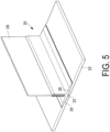
- FIG. 5 is a perspective view illustrating the shape of the joint 20 and the preform 22.
- the joint 20 of the present embodiment is a so-called pi ( ⁇ ) shaped joint which is provided on the preform 22, and in which a groove 24 is formed.
- the joint 20 is, for example, used in the body structure of an aircraft, and a member (a plate member 26 according to the present embodiment) that forms a part of the body structure is inserted into the groove 24.
- a member a plate member 26 according to the present embodiment
- the forward spar 7 or the rear spar 9 is the preform 22, and the rib 11 is the plate member 26.
- the plate member 26 is bonded to the joint 20 by filling the gap between the plate member 26 and the groove 24 with adhesive.
- the joint 20 is bonded to the preform 22 with adhesive. Note that there is no particular limitation on the method of bonding the preform 22 and the joint 20, and the method of bonding the joint 20 and the plate member 26.
- the plate member 26 is joined to the preform 22 by bonding using the joint 20, and without using fasteners.
- the material of the joint 20, the preform 22, and the plate member 26 is a composite material, for example, carbon fiber reinforced plastic (CFRP) or the like.
- CFRP carbon fiber reinforced plastic
- CFRP carbon fiber is used as a reinforcing material
- a synthetic resin is used as a matrix. Note that this is not a limitation, and a metal such as aluminum alloy may be used as the material of the joint 20, the preform 22, and the plate member 26.
- the joint 20 of the present embodiment is formed with an inclined part 28 formed on a bonding surface 25 with the preform 22.
- the inclined part 28 is inclined with respect to a plane (horizontal plane, the direction B in FIG. 3 ) that is perpendicular to the direction (vertical direction, direction A in FIG. 3 ) in which a tensile load is applied to the plate member 26.
- the inclined part 28 is inclined towards the preform 22.
- the inclined part 28 according to the present embodiment is inclined from edges 30 of the joint 20.
- the inclined part 28 is formed from two inclined surfaces 28A, 28B.
- a corner 32 is formed by the intersection of the inclined surfaces 28A, 28B. The corner 32 extends parallel to the lengthwise direction of the joint 20, in other words parallel to the edges 30 of the joint 20.
- a surface 34 (hereafter referred to as the "opposite surface") of the joint 20 opposite to the bonding surface 25 is inclined so that the thickness of the joint 20 becomes thinner from the center portion and tapers towards the edges 30.
- an indented part 38 corresponding to the shape of the inclined part 28 is formed on the preform 22 so that the inclined part 28 of the joint 20 is embedded into a bonding surface 36 with the joint 20.
- the joint 20 is bonded to the preform 22 with the inclined part 28 embedded in the preform 22.
- the angle of the inclined surfaces 28A, 28B with respect to the direction B is defined as the inclination angle ⁇ .
- the bonding surface 25 of the joint 20 and the bonding surface 36 of the preform 22 are collectively referred to as the bonding layer.
- the strength of the bonding layer (hereafter referred to as the "bond strength") is described with reference to FIGS. 6 to 10 .
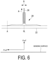
- FIG. 6 is a schematic view illustrating the bond strength of the bonding layer in which the indented part 38 is not formed in the preform 22.
- FIG. 7 is a schematic view illustrating the bond strength of the bonding layer in which the indented part 38 is formed in the preform 22.
- the bond strength includes the out-of-plane direction strength Ptall, which is the strength in the tensile direction of the plate member 26 (the direction A in FIGS. 6 and 7 , hereafter referred to as the "out-of-plane direction").
- the out-of-plane direction strength Ptall is the strength against tensile loads applied to the plate member 26 (hereafter referred to as "out-of-plane direction loads").
- the bond strength is divided into an in-plane direction strength Psall, which is the strength in the shear direction of the bonding layer (the direction B in FIGS. 6 and 7 , hereafter referred to as the "in-plane direction").
- the in-plane direction strength Psall has a strength component in the out-of-plane direction. Therefore the theoretical bond strength Pall against out-of-plane direction loads includes the sine component (Psall ⁇ sin ⁇ ) of the in-plane direction bond strength Psall in addition to the out-of-plane direction bond strength Ptall, as indicated in Equation (2).
- Pall Ptall + Psall ⁇ sin ⁇
- the bond strength is greater when the indented part 38 is formed in the preform 22 and the bonding layer is inclined, compared with when the bonding layer is flat.
- FIG. 8 is an overall view of a numerical analysis model 50
- FIG. 9 is an enlarged view of the region B in FIG. 8 .
- the numerical analysis model 50 is formed from a preform model 52 in which the indented part 38 is formed, and a joint model 54 in which the inclined part 28 is formed.
- the joint model 54 is a model of the joint 20 and the plate member 26 combined.
- the numerical analysis conditions included constraints applied to both edges (edges A, B) of the preform model 52, and the load applied to the joint model 54 in the out-of-plane direction (out-of-plane direction load).
- E about 60,000 MPa
- E about 40,000 MPa
- E about 3000 MPa
- E the longitudinal elastic modulus (Young's modulus).
- numerical analysis was carried out under the same conditions with a numerical analysis model 50 formed from a preform model 52 in which the indented part 38 was not formed and a joint model 54 in which the inclined part 28 was not formed.
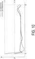
- FIG. 10 is a graph showing the numerical analysis results.
- the broken line in FIG. 10 shows the numerical analysis results for the numerical analysis model 50 in which the indented part 38 is not formed in the preform 22.
- the continuous line shows the numerical analysis results for the numerical analysis model 50 in which the indented part 38 is formed in the preform 22.
- the horizontal axis in FIG. 10 is the X direction of the numerical analysis model 50, the coordinate A indicates the edge of the bonding layer model 58, and the coordinate CL indicates the center of the bonding layer model 58 (see also FIG. 9 ).
- the vertical axis indicates the magnitude of the stress produced by the out-of-plane direction load.
- the peak stress is produced at the edge (coordinate A) of the bonding layer model 58 due to the out-of-plane direction load.
- the peak stress at the edge of the bonding layer model 58 (coordinate A) is larger in the numerical analysis model 50 in which the indented part 38 is not formed compared with the numerical analysis model 50 in which the indented part 38 is formed. The reason for this is because the difference in stiffness between the preform 22 and the joint 20 is relieved by forming the indented part 38.
- the stress at the edge of the bonding layer model 58 is reduced by about 60% compared with the case in which the indented part 38 is not formed. In this way, by forming the indented part 38, the bond strength is improved overall by a factor of about 2.5.
- the opposite surface 34 is inclined towards the edge 30. In this way, in the joint 20 of the present embodiment, the difference in stiffness between the joint 20 and the preform 22 is reduced compared with the case in which the edge 30 is, for example, perpendicular to the preform 22.
- the joint 20 of the present embodiment is formed with the two inclined surfaces 28A, 28B, so the bond strength of the bonding surface 25 can be uniform on the left and right.
- the joint 20 of the present embodiment joins the plate member 26 to the preform 22, and the inclined part 28, which is inclined relative to a surface that is orthogonal to the direction in which a tensile load is applied to the plate member 26, is formed on the bonding surface 25 with the preform 22. Also, the indented part 38 corresponding to the shape of the inclined part 28 is formed on the preform 22 so that the inclined part 28 of the joint 20 is embedded into the indented part 38. The joint 20 is embedded in and bonded to the preform 22.
- the strength of the bonding surface between the joint 20 and the preform 22 can be increased.
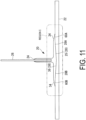
- FIG. 11 is a side view illustrating the shape of the joint 20 and the preform 22 according to the first modification of the present invention
- FIG. 12 is an enlarged view of the region C illustrated in FIG. 11 . Note that constituent parts in FIGS. 11 and 12 that are the same as in FIGS. 3 and 4 are given the same reference signs as in FIGS. 3 and 4 , and their description is omitted.
- flat portions 60A, 60B are formed from the edges 30 of the bonding surface 25 towards the center direction of the joint 20, and the inclined surfaces 28A, 28B are formed from the edges of the flat portions 60A, 60B towards the center direction.
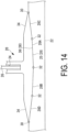
- FIG. 13 is a side view illustrating the shape of the joint 20 and the preform 22 according to the second modification of the present invention
- FIG. 14 is an enlarged view of the region D illustrated in FIG. 13 . Note that constituent parts in FIGS. 13 and 14 that are the same as in FIGS. 3 and 4 are given the same reference signs as in FIGS. 3 and 4 , and their description is omitted.
- the inclined part 28 according to the third modification is formed with a plurality of inclined surfaces 28A, 28B, 28C, 28D with different inclination angles. Note that in the example in FIGS. 13 and 14 , the inclined surface 28A and the inclined surface 28B have the same inclination angle, and the inclined surface 28C and the inclined surface 28D have the same inclination angle. However this is not a limitation, and the inclined part 28 may be formed with four or more inclined surfaces.
- the inclination angle can be varied in accordance with the load that is expected to be applied to the joint 20, and the strength of the bonding surface 25 can be adjusted.
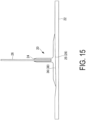
- FIG. 15 is a side view illustrating the shape of the joint 20 and the preform 22 according to this modification.
- the inclined part 28 according to the modification is formed with a single inclined surface.
- the strength of the bonding surface 25 between the joint 20 and the preform 22 can be increased with a simple configuration.
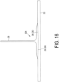
- FIG. 16 is a side view illustrating the shape of a joint 20A and the preform 22 according to the modification.
- the joint 20A according to the modification is a T-shaped joint, not a pi-shaped joint as described above.
- FIG. 17 is a side view illustrating the shape of a joint 20B and the preform 22 according to the modification.
- the joint 20B according to the modification is an L-shaped joint, not a pi-shaped joint as described above.
- the joint 20 was described for a form used in an aircraft structure, but the present invention is not limited to this, and the joint 20 may be a form that is used in structures other than an aircraft.
Landscapes
- Engineering & Computer Science (AREA)
- Mechanical Engineering (AREA)
- Aviation & Aerospace Engineering (AREA)
- General Engineering & Computer Science (AREA)
- Standing Axle, Rod, Or Tube Structures Coupled By Welding, Adhesion, Or Deposition (AREA)
- Lining Or Joining Of Plastics Or The Like (AREA)
- Connection Of Plates (AREA)
- Pressure Welding/Diffusion-Bonding (AREA)
- Laminated Bodies (AREA)
Claims (5)
- Eine zusammengesetzte Struktur, die eine Verbindung (20) und eine Vorform (22) aufweist, die ein Element (26) mit der Vorform (22) durch die Verbindung (20) verbindet,wobei die Verbindung (20) einen geneigten Teil (28) aufweist, der auf einer Verbindungsoberfläche (25) mit der Vorform (22) ausgebildet ist und in Richtung der Vorform (22) relativ zu einer Oberfläche geneigt ist, die orthogonal zu einer Richtung ist, in der erwartet wird, dass eine Zugbelastung auf das Element (26) aufgebracht wird,wobei der geneigte Teil (28) mit einer Vielzahl von geneigten Oberflächen (28A, B; 28A-D) ausgebildet ist und eine Ecke (32) durch einen Schnittpunkt der geneigten Oberflächen (28A, B; 28A-D) ausgebildet ist,wobei die Vorform (22) mit einem eingedrückten Teil (38) ausgebildet ist, der zu einer Form des geneigten Teils (28) der Verbindung (20) korrespondiert,wobei der geneigte Teil (28) in den eingedrückten Teil (38) der Vorform (22) eingebettet ist und mit der Vorform (22) verbunden ist,wobei die Verbindung (20) eine Pi-förmige Verbindung ist, in der eine Nut (24) ausgebildet ist, in die das Element (26) einzusetzen ist, undwobei das Element (26) ein Plattenelement ist.
- Die zusammengesetzte Struktur nach Anspruch 1, wobei eine Oberfläche der Verbindung (20) gegenüber der Verbindungsoberfläche (25) zu einer Kante (30) der Verbindung (20) hin geneigt ist, so dass eine Dicke der Verbindung (20) an der Kante (30) dünner ist als eine Dicke der Verbindung (20) in einer Mitte.
- Die zusammengesetzte Struktur nach Anspruch 2, wobei sich die Dicke der Verbindung (20) in Richtung der Kante (30) verjüngt.
- Die zusammengesetzte Struktur nach einem der Ansprüche 1 bis 3, wobei der geneigte Teil (28) mit einer Vielzahl von geneigten Oberflächen (28A-D) mit unterschiedlichen Winkeln in Bezug auf die Vorform (22) ausgebildet ist.
- Eine Flugzeugstruktur, aufweisend:
die in einem der Ansprüche 1 bis 4 beschriebene zusammengesetzte Struktur.
Applications Claiming Priority (2)
| Application Number | Priority Date | Filing Date | Title |
|---|---|---|---|
| JP2013207662A JP6169465B2 (ja) | 2013-10-02 | 2013-10-02 | 継手及び航空機構造 |
| PCT/JP2014/065864 WO2015049898A1 (ja) | 2013-10-02 | 2014-06-16 | 継手及び航空機構造 |
Publications (3)
| Publication Number | Publication Date |
|---|---|
| EP3029339A1 EP3029339A1 (de) | 2016-06-08 |
| EP3029339A4 EP3029339A4 (de) | 2016-09-14 |
| EP3029339B1 true EP3029339B1 (de) | 2024-07-31 |
Family
ID=52778495
Family Applications (1)
| Application Number | Title | Priority Date | Filing Date |
|---|---|---|---|
| EP14851251.0A Active EP3029339B1 (de) | 2013-10-02 | 2014-06-16 | Verbindung und luftfahrzeugstruktur |
Country Status (8)
| Country | Link |
|---|---|
| US (1) | US10040538B2 (de) |
| EP (1) | EP3029339B1 (de) |
| JP (1) | JP6169465B2 (de) |
| CN (1) | CN105518315B (de) |
| BR (1) | BR112016004953A2 (de) |
| CA (1) | CA2923152C (de) |
| RU (1) | RU2632552C1 (de) |
| WO (1) | WO2015049898A1 (de) |
Families Citing this family (10)
| Publication number | Priority date | Publication date | Assignee | Title |
|---|---|---|---|---|
| GB2538098A (en) * | 2015-05-07 | 2016-11-09 | Airbus Operations Ltd | A structural component |
| US10605631B2 (en) * | 2017-08-03 | 2020-03-31 | Sikorsky Aircraft Corporation | Structural pi joint with integrated fiber optic sensing |
| US10723436B2 (en) * | 2017-08-14 | 2020-07-28 | The Boeing Company | Methods and apparatus to increase strength and toughness of aircraft structural components |
| US10889364B1 (en) * | 2017-09-15 | 2021-01-12 | Northrop Grumman Systems Corporation | Aircraft full depth pi preform joints |
| US11332228B2 (en) * | 2018-04-06 | 2022-05-17 | Aurora Flight Sciences Corporation | Aircraft fuselage with composite pre-form |
| MX2021002823A (es) * | 2018-09-11 | 2021-08-11 | Tpi Composites Inc | Perfiles de posicionamiento para pultrusiones en tapas de larguero de aspa eolica. |
| JP7543168B2 (ja) * | 2021-02-24 | 2024-09-02 | 株式会社Subaru | 接着継手の製造方法 |
| US12037938B1 (en) | 2023-06-30 | 2024-07-16 | General Electric Company | Composite airfoil assembly for a turbine engine |
| US12163533B1 (en) | 2023-06-30 | 2024-12-10 | General Electric Company | Composite airfoil assembly for a turbine engine |
| CN118438211A (zh) * | 2024-06-07 | 2024-08-06 | 上海拓璞数控科技股份有限公司 | 复合材料板和金属框架组成的盒体框架结构及生产方法 |
Family Cites Families (19)
| Publication number | Priority date | Publication date | Assignee | Title |
|---|---|---|---|---|
| GB9810528D0 (en) * | 1998-05-15 | 1998-07-15 | British Aerospace | Manufacture of stiffened composite structures |
| US6276866B1 (en) * | 1998-09-22 | 2001-08-21 | Elbert Rutan | Tensioned structural composite joint |
| RU12819U1 (ru) * | 1999-04-28 | 2000-02-10 | Егер Владимир Сергеевич | Композитное кессонное крыло легкого самолета |
| RU2144485C1 (ru) * | 1999-07-06 | 2000-01-20 | Закрытое акционерное общество "Интеллект" | Нервюра летательного аппарата |
| US6374570B1 (en) | 2000-08-25 | 2002-04-23 | Lockheed Martin Corporation | Apparatus and method for joining dissimilar materials to form a structural support member |
| US6849150B1 (en) * | 2001-01-16 | 2005-02-01 | Lockheed Martin Corporation | System and method of forming structural assemblies with 3-D woven joint pre-forms |
| US6749155B2 (en) | 2002-09-13 | 2004-06-15 | The Boeing Company | Composite assembly with integrated composite joints |
| US7555873B2 (en) | 2004-11-30 | 2009-07-07 | The Boeing Company | Self-locating feature for a pi-joint assembly |
| US8272618B2 (en) | 2004-11-30 | 2012-09-25 | The Boeing Company | Minimum bond thickness assembly feature assurance |
| US20060115320A1 (en) | 2004-11-30 | 2006-06-01 | The Boeing Company | Determinant assembly features for vehicle structures |
| FR2898410B1 (fr) | 2006-03-07 | 2008-05-09 | Airbus France Sas | Procede de caracterisation de la tenue en fatigue d'une piece a partir de son profil de surface |
| US9016551B2 (en) * | 2006-11-02 | 2015-04-28 | The Boeing Company | Method and apparatus to construct metal securement member for an aircraft |
| US8475895B2 (en) * | 2006-11-21 | 2013-07-02 | General Electric Company | Articles comprising composite structures having mounting flanges |
| US7690164B2 (en) * | 2006-12-05 | 2010-04-06 | Lockheed Martin Corporation | System, method, and apparatus for structural lug formed from a combination of metal and composite laminate materials |
| EP2595876B1 (de) | 2010-07-20 | 2016-07-06 | Airbus Operations GmbH | Hauptlast-tragende beplankungsschale sowie strukturbauteil mit zumindest einer hauptlast-tragenden beplankungsschale |
| GB201016279D0 (en) | 2010-09-28 | 2010-11-10 | Airbus Operations Ltd | Stiffener run-out |
| ES2400129B1 (es) * | 2011-05-30 | 2014-06-18 | Airbus Operations, S.L. | Método de fabricación de larguerillos con forma de "t" con un ángulo diferente de 90� entre el alma y el pie |
| GB201200912D0 (en) | 2012-01-19 | 2012-02-29 | Airbus Operations Ltd | Fastener receptacle strip |
| US8703269B2 (en) * | 2012-02-14 | 2014-04-22 | Gulfstream Aerospace Corporation | Reinforced composite structures for aircrafts and methods for making the same |
-
2013
- 2013-10-02 JP JP2013207662A patent/JP6169465B2/ja active Active
-
2014
- 2014-06-16 EP EP14851251.0A patent/EP3029339B1/de active Active
- 2014-06-16 BR BR112016004953A patent/BR112016004953A2/pt active Search and Examination
- 2014-06-16 CN CN201480048925.1A patent/CN105518315B/zh not_active Expired - Fee Related
- 2014-06-16 RU RU2016107659A patent/RU2632552C1/ru active
- 2014-06-16 WO PCT/JP2014/065864 patent/WO2015049898A1/ja not_active Ceased
- 2014-06-16 US US14/916,311 patent/US10040538B2/en active Active
- 2014-06-16 CA CA2923152A patent/CA2923152C/en not_active Expired - Fee Related
Also Published As
| Publication number | Publication date |
|---|---|
| JP2015072041A (ja) | 2015-04-16 |
| EP3029339A1 (de) | 2016-06-08 |
| US10040538B2 (en) | 2018-08-07 |
| CN105518315B (zh) | 2018-07-06 |
| RU2632552C1 (ru) | 2017-10-05 |
| WO2015049898A1 (ja) | 2015-04-09 |
| CA2923152A1 (en) | 2015-04-09 |
| JP6169465B2 (ja) | 2017-07-26 |
| CN105518315A (zh) | 2016-04-20 |
| BR112016004953A2 (pt) | 2020-05-19 |
| CA2923152C (en) | 2019-01-08 |
| EP3029339A4 (de) | 2016-09-14 |
| US20160194071A1 (en) | 2016-07-07 |
Similar Documents
| Publication | Publication Date | Title |
|---|---|---|
| CA2923152C (en) | Joint, and aircraft structure | |
| US10071794B2 (en) | Joint, and aircraft structure | |
| CN103874629B (zh) | 高度渐缩的弯曲复合纵梁及相应面板 | |
| US9371127B2 (en) | Composite structure comprising a stringer with a pad embedded in the recess of a panel and method of transmitting forces | |
| JP5308533B2 (ja) | 複合材構造体、これを備えた航空機主翼および航空機胴体 | |
| JP5808111B2 (ja) | 航空機用複合材構造体、これを備えた航空機主翼および航空機胴体 | |
| US9371128B2 (en) | Structural component comprising at least one main-load-bearing covering shell and a carrier structure for fixing the main-load-bearing covering shell, and flow body comprising such a structural component | |
| US8679616B2 (en) | Skew-angle radius filler | |
| US11020912B2 (en) | Joint structure | |
| US10414479B2 (en) | System and method for interconnecting composite structures | |
| WO2012105416A1 (ja) | 複合材構造体およびこれを備えた航空機主翼 | |
| KR20130139929A (ko) | 보강재 런-아웃 | |
| JP6215571B2 (ja) | 航空機、機体、及び関連の方法 | |
| US11339813B2 (en) | Joint structure | |
| EP4067066B1 (de) | Verbindungsstruktur und verfahren zur herstellung einer verbindungsstruktur |
Legal Events
| Date | Code | Title | Description |
|---|---|---|---|
| PUAI | Public reference made under article 153(3) epc to a published international application that has entered the european phase |
Free format text: ORIGINAL CODE: 0009012 |
|
| 17P | Request for examination filed |
Effective date: 20160303 |
|
| AK | Designated contracting states |
Kind code of ref document: A1 Designated state(s): AL AT BE BG CH CY CZ DE DK EE ES FI FR GB GR HR HU IE IS IT LI LT LU LV MC MK MT NL NO PL PT RO RS SE SI SK SM TR |
|
| AX | Request for extension of the european patent |
Extension state: BA ME |
|
| A4 | Supplementary search report drawn up and despatched |
Effective date: 20160812 |
|
| RIC1 | Information provided on ipc code assigned before grant |
Ipc: B29C 65/48 20060101ALI20160808BHEP Ipc: F16B 11/00 20060101AFI20160808BHEP Ipc: B29C 65/00 20060101ALI20160808BHEP Ipc: B64C 1/00 20060101ALI20160808BHEP Ipc: B64C 3/18 20060101ALI20160808BHEP Ipc: B64C 3/26 20060101ALI20160808BHEP Ipc: B29L 31/30 20060101ALN20160808BHEP |
|
| DAX | Request for extension of the european patent (deleted) | ||
| STAA | Information on the status of an ep patent application or granted ep patent |
Free format text: STATUS: EXAMINATION IS IN PROGRESS |
|
| 17Q | First examination report despatched |
Effective date: 20200529 |
|
| GRAP | Despatch of communication of intention to grant a patent |
Free format text: ORIGINAL CODE: EPIDOSNIGR1 |
|
| STAA | Information on the status of an ep patent application or granted ep patent |
Free format text: STATUS: GRANT OF PATENT IS INTENDED |
|
| INTG | Intention to grant announced |
Effective date: 20240219 |
|
| GRAS | Grant fee paid |
Free format text: ORIGINAL CODE: EPIDOSNIGR3 |
|
| GRAA | (expected) grant |
Free format text: ORIGINAL CODE: 0009210 |
|
| STAA | Information on the status of an ep patent application or granted ep patent |
Free format text: STATUS: THE PATENT HAS BEEN GRANTED |
|
| AK | Designated contracting states |
Kind code of ref document: B1 Designated state(s): AL AT BE BG CH CY CZ DE DK EE ES FI FR GB GR HR HU IE IS IT LI LT LU LV MC MK MT NL NO PL PT RO RS SE SI SK SM TR |
|
| REG | Reference to a national code |
Ref country code: CH Ref legal event code: EP Ref country code: GB Ref legal event code: FG4D |
|
| REG | Reference to a national code |
Ref country code: DE Ref legal event code: R096 Ref document number: 602014090612 Country of ref document: DE |
|
| REG | Reference to a national code |
Ref country code: IE Ref legal event code: FG4D |
|
| REG | Reference to a national code |
Ref country code: LT Ref legal event code: MG9D |
|
| REG | Reference to a national code |
Ref country code: NL Ref legal event code: MP Effective date: 20240731 |
|
| PG25 | Lapsed in a contracting state [announced via postgrant information from national office to epo] |
Ref country code: PT Free format text: LAPSE BECAUSE OF FAILURE TO SUBMIT A TRANSLATION OF THE DESCRIPTION OR TO PAY THE FEE WITHIN THE PRESCRIBED TIME-LIMIT Effective date: 20241202 |
|
| REG | Reference to a national code |
Ref country code: AT Ref legal event code: MK05 Ref document number: 1708698 Country of ref document: AT Kind code of ref document: T Effective date: 20240731 |
|
| PG25 | Lapsed in a contracting state [announced via postgrant information from national office to epo] |
Ref country code: PT Free format text: LAPSE BECAUSE OF FAILURE TO SUBMIT A TRANSLATION OF THE DESCRIPTION OR TO PAY THE FEE WITHIN THE PRESCRIBED TIME-LIMIT Effective date: 20241202 |
|
| PG25 | Lapsed in a contracting state [announced via postgrant information from national office to epo] |
Ref country code: NO Free format text: LAPSE BECAUSE OF FAILURE TO SUBMIT A TRANSLATION OF THE DESCRIPTION OR TO PAY THE FEE WITHIN THE PRESCRIBED TIME-LIMIT Effective date: 20241031 |
|
| PG25 | Lapsed in a contracting state [announced via postgrant information from national office to epo] |
Ref country code: FI Free format text: LAPSE BECAUSE OF FAILURE TO SUBMIT A TRANSLATION OF THE DESCRIPTION OR TO PAY THE FEE WITHIN THE PRESCRIBED TIME-LIMIT Effective date: 20240731 Ref country code: NL Free format text: LAPSE BECAUSE OF FAILURE TO SUBMIT A TRANSLATION OF THE DESCRIPTION OR TO PAY THE FEE WITHIN THE PRESCRIBED TIME-LIMIT Effective date: 20240731 Ref country code: PL Free format text: LAPSE BECAUSE OF FAILURE TO SUBMIT A TRANSLATION OF THE DESCRIPTION OR TO PAY THE FEE WITHIN THE PRESCRIBED TIME-LIMIT Effective date: 20240731 Ref country code: GR Free format text: LAPSE BECAUSE OF FAILURE TO SUBMIT A TRANSLATION OF THE DESCRIPTION OR TO PAY THE FEE WITHIN THE PRESCRIBED TIME-LIMIT Effective date: 20241101 |
|
| PG25 | Lapsed in a contracting state [announced via postgrant information from national office to epo] |
Ref country code: BG Free format text: LAPSE BECAUSE OF FAILURE TO SUBMIT A TRANSLATION OF THE DESCRIPTION OR TO PAY THE FEE WITHIN THE PRESCRIBED TIME-LIMIT Effective date: 20240731 |
|
| PG25 | Lapsed in a contracting state [announced via postgrant information from national office to epo] |
Ref country code: LV Free format text: LAPSE BECAUSE OF FAILURE TO SUBMIT A TRANSLATION OF THE DESCRIPTION OR TO PAY THE FEE WITHIN THE PRESCRIBED TIME-LIMIT Effective date: 20240731 |
|
| PG25 | Lapsed in a contracting state [announced via postgrant information from national office to epo] |
Ref country code: AT Free format text: LAPSE BECAUSE OF FAILURE TO SUBMIT A TRANSLATION OF THE DESCRIPTION OR TO PAY THE FEE WITHIN THE PRESCRIBED TIME-LIMIT Effective date: 20240731 Ref country code: IS Free format text: LAPSE BECAUSE OF FAILURE TO SUBMIT A TRANSLATION OF THE DESCRIPTION OR TO PAY THE FEE WITHIN THE PRESCRIBED TIME-LIMIT Effective date: 20241130 |
|
| PG25 | Lapsed in a contracting state [announced via postgrant information from national office to epo] |
Ref country code: HR Free format text: LAPSE BECAUSE OF FAILURE TO SUBMIT A TRANSLATION OF THE DESCRIPTION OR TO PAY THE FEE WITHIN THE PRESCRIBED TIME-LIMIT Effective date: 20240731 |
|
| PG25 | Lapsed in a contracting state [announced via postgrant information from national office to epo] |
Ref country code: ES Free format text: LAPSE BECAUSE OF FAILURE TO SUBMIT A TRANSLATION OF THE DESCRIPTION OR TO PAY THE FEE WITHIN THE PRESCRIBED TIME-LIMIT Effective date: 20240731 Ref country code: RS Free format text: LAPSE BECAUSE OF FAILURE TO SUBMIT A TRANSLATION OF THE DESCRIPTION OR TO PAY THE FEE WITHIN THE PRESCRIBED TIME-LIMIT Effective date: 20241031 |
|
| PG25 | Lapsed in a contracting state [announced via postgrant information from national office to epo] |
Ref country code: RS Free format text: LAPSE BECAUSE OF FAILURE TO SUBMIT A TRANSLATION OF THE DESCRIPTION OR TO PAY THE FEE WITHIN THE PRESCRIBED TIME-LIMIT Effective date: 20241031 Ref country code: PL Free format text: LAPSE BECAUSE OF FAILURE TO SUBMIT A TRANSLATION OF THE DESCRIPTION OR TO PAY THE FEE WITHIN THE PRESCRIBED TIME-LIMIT Effective date: 20240731 Ref country code: NO Free format text: LAPSE BECAUSE OF FAILURE TO SUBMIT A TRANSLATION OF THE DESCRIPTION OR TO PAY THE FEE WITHIN THE PRESCRIBED TIME-LIMIT Effective date: 20241031 Ref country code: NL Free format text: LAPSE BECAUSE OF FAILURE TO SUBMIT A TRANSLATION OF THE DESCRIPTION OR TO PAY THE FEE WITHIN THE PRESCRIBED TIME-LIMIT Effective date: 20240731 Ref country code: LV Free format text: LAPSE BECAUSE OF FAILURE TO SUBMIT A TRANSLATION OF THE DESCRIPTION OR TO PAY THE FEE WITHIN THE PRESCRIBED TIME-LIMIT Effective date: 20240731 Ref country code: IS Free format text: LAPSE BECAUSE OF FAILURE TO SUBMIT A TRANSLATION OF THE DESCRIPTION OR TO PAY THE FEE WITHIN THE PRESCRIBED TIME-LIMIT Effective date: 20241130 Ref country code: HR Free format text: LAPSE BECAUSE OF FAILURE TO SUBMIT A TRANSLATION OF THE DESCRIPTION OR TO PAY THE FEE WITHIN THE PRESCRIBED TIME-LIMIT Effective date: 20240731 Ref country code: GR Free format text: LAPSE BECAUSE OF FAILURE TO SUBMIT A TRANSLATION OF THE DESCRIPTION OR TO PAY THE FEE WITHIN THE PRESCRIBED TIME-LIMIT Effective date: 20241101 Ref country code: FI Free format text: LAPSE BECAUSE OF FAILURE TO SUBMIT A TRANSLATION OF THE DESCRIPTION OR TO PAY THE FEE WITHIN THE PRESCRIBED TIME-LIMIT Effective date: 20240731 Ref country code: ES Free format text: LAPSE BECAUSE OF FAILURE TO SUBMIT A TRANSLATION OF THE DESCRIPTION OR TO PAY THE FEE WITHIN THE PRESCRIBED TIME-LIMIT Effective date: 20240731 Ref country code: BG Free format text: LAPSE BECAUSE OF FAILURE TO SUBMIT A TRANSLATION OF THE DESCRIPTION OR TO PAY THE FEE WITHIN THE PRESCRIBED TIME-LIMIT Effective date: 20240731 Ref country code: AT Free format text: LAPSE BECAUSE OF FAILURE TO SUBMIT A TRANSLATION OF THE DESCRIPTION OR TO PAY THE FEE WITHIN THE PRESCRIBED TIME-LIMIT Effective date: 20240731 |
|
| PG25 | Lapsed in a contracting state [announced via postgrant information from national office to epo] |
Ref country code: RO Free format text: LAPSE BECAUSE OF FAILURE TO SUBMIT A TRANSLATION OF THE DESCRIPTION OR TO PAY THE FEE WITHIN THE PRESCRIBED TIME-LIMIT Effective date: 20240731 Ref country code: SM Free format text: LAPSE BECAUSE OF FAILURE TO SUBMIT A TRANSLATION OF THE DESCRIPTION OR TO PAY THE FEE WITHIN THE PRESCRIBED TIME-LIMIT Effective date: 20240731 Ref country code: DK Free format text: LAPSE BECAUSE OF FAILURE TO SUBMIT A TRANSLATION OF THE DESCRIPTION OR TO PAY THE FEE WITHIN THE PRESCRIBED TIME-LIMIT Effective date: 20240731 |
|
| PG25 | Lapsed in a contracting state [announced via postgrant information from national office to epo] |
Ref country code: EE Free format text: LAPSE BECAUSE OF FAILURE TO SUBMIT A TRANSLATION OF THE DESCRIPTION OR TO PAY THE FEE WITHIN THE PRESCRIBED TIME-LIMIT Effective date: 20240731 |
|
| PG25 | Lapsed in a contracting state [announced via postgrant information from national office to epo] |
Ref country code: CZ Free format text: LAPSE BECAUSE OF FAILURE TO SUBMIT A TRANSLATION OF THE DESCRIPTION OR TO PAY THE FEE WITHIN THE PRESCRIBED TIME-LIMIT Effective date: 20240731 |
|
| PG25 | Lapsed in a contracting state [announced via postgrant information from national office to epo] |
Ref country code: SK Free format text: LAPSE BECAUSE OF FAILURE TO SUBMIT A TRANSLATION OF THE DESCRIPTION OR TO PAY THE FEE WITHIN THE PRESCRIBED TIME-LIMIT Effective date: 20240731 |
|
| REG | Reference to a national code |
Ref country code: DE Ref legal event code: R097 Ref document number: 602014090612 Country of ref document: DE |
|
| PLBE | No opposition filed within time limit |
Free format text: ORIGINAL CODE: 0009261 |
|
| STAA | Information on the status of an ep patent application or granted ep patent |
Free format text: STATUS: NO OPPOSITION FILED WITHIN TIME LIMIT |
|
| 26N | No opposition filed |
Effective date: 20250501 |
|
| PG25 | Lapsed in a contracting state [announced via postgrant information from national office to epo] |
Ref country code: SE Free format text: LAPSE BECAUSE OF FAILURE TO SUBMIT A TRANSLATION OF THE DESCRIPTION OR TO PAY THE FEE WITHIN THE PRESCRIBED TIME-LIMIT Effective date: 20240731 |
|
| REG | Reference to a national code |
Ref country code: CH Ref legal event code: H13 Free format text: ST27 STATUS EVENT CODE: U-0-0-H10-H13 (AS PROVIDED BY THE NATIONAL OFFICE) Effective date: 20260127 |
|
| PG25 | Lapsed in a contracting state [announced via postgrant information from national office to epo] |
Ref country code: MC Free format text: LAPSE BECAUSE OF FAILURE TO SUBMIT A TRANSLATION OF THE DESCRIPTION OR TO PAY THE FEE WITHIN THE PRESCRIBED TIME-LIMIT Effective date: 20240731 |
|
| PG25 | Lapsed in a contracting state [announced via postgrant information from national office to epo] |
Ref country code: LU Free format text: LAPSE BECAUSE OF NON-PAYMENT OF DUE FEES Effective date: 20250616 |
|
| REG | Reference to a national code |
Ref country code: BE Ref legal event code: MM Effective date: 20250630 |
|
| PG25 | Lapsed in a contracting state [announced via postgrant information from national office to epo] |
Ref country code: IE Free format text: LAPSE BECAUSE OF NON-PAYMENT OF DUE FEES Effective date: 20250616 |
|
| PG25 | Lapsed in a contracting state [announced via postgrant information from national office to epo] |
Ref country code: BE Free format text: LAPSE BECAUSE OF NON-PAYMENT OF DUE FEES Effective date: 20250630 |
|
| PG25 | Lapsed in a contracting state [announced via postgrant information from national office to epo] |
Ref country code: CH Free format text: LAPSE BECAUSE OF NON-PAYMENT OF DUE FEES Effective date: 20250630 |
|
| PG25 | Lapsed in a contracting state [announced via postgrant information from national office to epo] |
Ref country code: LT Free format text: LAPSE BECAUSE OF FAILURE TO SUBMIT A TRANSLATION OF THE DESCRIPTION OR TO PAY THE FEE WITHIN THE PRESCRIBED TIME-LIMIT Effective date: 20240731 |
|
| PGFP | Annual fee paid to national office [announced via postgrant information from national office to epo] |
Ref country code: GB Payment date: 20260505 Year of fee payment: 13 |
|
| PGFP | Annual fee paid to national office [announced via postgrant information from national office to epo] |
Ref country code: IT Payment date: 20260522 Year of fee payment: 13 |
|
| PGFP | Annual fee paid to national office [announced via postgrant information from national office to epo] |
Ref country code: DE Payment date: 20260430 Year of fee payment: 13 |
|
| PGFP | Annual fee paid to national office [announced via postgrant information from national office to epo] |
Ref country code: FR Payment date: 20260511 Year of fee payment: 13 |
|
| PG25 | Lapsed in a contracting state [announced via postgrant information from national office to epo] |
Ref country code: CY Free format text: LAPSE BECAUSE OF FAILURE TO SUBMIT A TRANSLATION OF THE DESCRIPTION OR TO PAY THE FEE WITHIN THE PRESCRIBED TIME-LIMIT Effective date: 20240731 |