EP4067066B1 - Verbindungsstruktur und verfahren zur herstellung einer verbindungsstruktur - Google Patents
Verbindungsstruktur und verfahren zur herstellung einer verbindungsstruktur Download PDFInfo
- Publication number
- EP4067066B1 EP4067066B1 EP20911838.9A EP20911838A EP4067066B1 EP 4067066 B1 EP4067066 B1 EP 4067066B1 EP 20911838 A EP20911838 A EP 20911838A EP 4067066 B1 EP4067066 B1 EP 4067066B1
- Authority
- EP
- European Patent Office
- Prior art keywords
- joint structure
- boundary
- raised portion
- bonded
- reinforcing material
- Prior art date
- Legal status (The legal status is an assumption and is not a legal conclusion. Google has not performed a legal analysis and makes no representation as to the accuracy of the status listed.)
- Active
Links
Images



Classifications
-
- B—PERFORMING OPERATIONS; TRANSPORTING
- B29—WORKING OF PLASTICS; WORKING OF SUBSTANCES IN A PLASTIC STATE IN GENERAL
- B29C—SHAPING OR JOINING OF PLASTICS; SHAPING OF MATERIAL IN A PLASTIC STATE, NOT OTHERWISE PROVIDED FOR; AFTER-TREATMENT OF THE SHAPED PRODUCTS, e.g. REPAIRING
- B29C65/00—Joining or sealing of preformed parts, e.g. welding of plastics materials; Apparatus therefor
- B29C65/48—Joining or sealing of preformed parts, e.g. welding of plastics materials; Apparatus therefor using adhesives, i.e. using supplementary joining material; solvent bonding
-
- B—PERFORMING OPERATIONS; TRANSPORTING
- B32—LAYERED PRODUCTS
- B32B—LAYERED PRODUCTS, i.e. PRODUCTS BUILT-UP OF STRATA OF FLAT OR NON-FLAT, e.g. CELLULAR OR HONEYCOMB, FORM
- B32B3/00—Layered products comprising a layer with external or internal discontinuities or unevennesses, or a layer of non-planar shape; Layered products comprising a layer having particular features of form
- B32B3/02—Layered products comprising a layer with external or internal discontinuities or unevennesses, or a layer of non-planar shape; Layered products comprising a layer having particular features of form characterised by features of form at particular places, e.g. in edge regions
- B32B3/08—Layered products comprising a layer with external or internal discontinuities or unevennesses, or a layer of non-planar shape; Layered products comprising a layer having particular features of form characterised by features of form at particular places, e.g. in edge regions characterised by added members at particular parts
-
- B—PERFORMING OPERATIONS; TRANSPORTING
- B29—WORKING OF PLASTICS; WORKING OF SUBSTANCES IN A PLASTIC STATE IN GENERAL
- B29C—SHAPING OR JOINING OF PLASTICS; SHAPING OF MATERIAL IN A PLASTIC STATE, NOT OTHERWISE PROVIDED FOR; AFTER-TREATMENT OF THE SHAPED PRODUCTS, e.g. REPAIRING
- B29C65/00—Joining or sealing of preformed parts, e.g. welding of plastics materials; Apparatus therefor
- B29C65/48—Joining or sealing of preformed parts, e.g. welding of plastics materials; Apparatus therefor using adhesives, i.e. using supplementary joining material; solvent bonding
- B29C65/4805—Joining or sealing of preformed parts, e.g. welding of plastics materials; Apparatus therefor using adhesives, i.e. using supplementary joining material; solvent bonding characterised by the type of adhesives
- B29C65/483—Reactive adhesives, e.g. chemically curing adhesives
-
- B—PERFORMING OPERATIONS; TRANSPORTING
- B29—WORKING OF PLASTICS; WORKING OF SUBSTANCES IN A PLASTIC STATE IN GENERAL
- B29C—SHAPING OR JOINING OF PLASTICS; SHAPING OF MATERIAL IN A PLASTIC STATE, NOT OTHERWISE PROVIDED FOR; AFTER-TREATMENT OF THE SHAPED PRODUCTS, e.g. REPAIRING
- B29C65/00—Joining or sealing of preformed parts, e.g. welding of plastics materials; Apparatus therefor
- B29C65/48—Joining or sealing of preformed parts, e.g. welding of plastics materials; Apparatus therefor using adhesives, i.e. using supplementary joining material; solvent bonding
- B29C65/50—Joining or sealing of preformed parts, e.g. welding of plastics materials; Apparatus therefor using adhesives, i.e. using supplementary joining material; solvent bonding using adhesive tape, e.g. thermoplastic tape; using threads or the like
- B29C65/5057—Joining or sealing of preformed parts, e.g. welding of plastics materials; Apparatus therefor using adhesives, i.e. using supplementary joining material; solvent bonding using adhesive tape, e.g. thermoplastic tape; using threads or the like positioned between the surfaces to be joined
-
- B—PERFORMING OPERATIONS; TRANSPORTING
- B29—WORKING OF PLASTICS; WORKING OF SUBSTANCES IN A PLASTIC STATE IN GENERAL
- B29C—SHAPING OR JOINING OF PLASTICS; SHAPING OF MATERIAL IN A PLASTIC STATE, NOT OTHERWISE PROVIDED FOR; AFTER-TREATMENT OF THE SHAPED PRODUCTS, e.g. REPAIRING
- B29C65/00—Joining or sealing of preformed parts, e.g. welding of plastics materials; Apparatus therefor
- B29C65/82—Testing the joint
- B29C65/8207—Testing the joint by mechanical methods
- B29C65/8223—Peel tests
-
- B—PERFORMING OPERATIONS; TRANSPORTING
- B29—WORKING OF PLASTICS; WORKING OF SUBSTANCES IN A PLASTIC STATE IN GENERAL
- B29C—SHAPING OR JOINING OF PLASTICS; SHAPING OF MATERIAL IN A PLASTIC STATE, NOT OTHERWISE PROVIDED FOR; AFTER-TREATMENT OF THE SHAPED PRODUCTS, e.g. REPAIRING
- B29C66/00—General aspects of processes or apparatus for joining preformed parts
- B29C66/01—General aspects dealing with the joint area or with the area to be joined
- B29C66/05—Particular design of joint configurations
- B29C66/10—Particular design of joint configurations particular design of the joint cross-sections
- B29C66/11—Joint cross-sections comprising a single joint-segment, i.e. one of the parts to be joined comprising a single joint-segment in the joint cross-section
- B29C66/112—Single lapped joints
-
- B—PERFORMING OPERATIONS; TRANSPORTING
- B29—WORKING OF PLASTICS; WORKING OF SUBSTANCES IN A PLASTIC STATE IN GENERAL
- B29C—SHAPING OR JOINING OF PLASTICS; SHAPING OF MATERIAL IN A PLASTIC STATE, NOT OTHERWISE PROVIDED FOR; AFTER-TREATMENT OF THE SHAPED PRODUCTS, e.g. REPAIRING
- B29C66/00—General aspects of processes or apparatus for joining preformed parts
- B29C66/01—General aspects dealing with the joint area or with the area to be joined
- B29C66/05—Particular design of joint configurations
- B29C66/10—Particular design of joint configurations particular design of the joint cross-sections
- B29C66/12—Joint cross-sections combining only two joint-segments; Tongue and groove joints; Tenon and mortise joints; Stepped joint cross-sections
- B29C66/128—Stepped joint cross-sections
- B29C66/1282—Stepped joint cross-sections comprising at least one overlap joint-segment
- B29C66/12821—Stepped joint cross-sections comprising at least one overlap joint-segment comprising at least two overlap joint-segments
-
- B—PERFORMING OPERATIONS; TRANSPORTING
- B29—WORKING OF PLASTICS; WORKING OF SUBSTANCES IN A PLASTIC STATE IN GENERAL
- B29C—SHAPING OR JOINING OF PLASTICS; SHAPING OF MATERIAL IN A PLASTIC STATE, NOT OTHERWISE PROVIDED FOR; AFTER-TREATMENT OF THE SHAPED PRODUCTS, e.g. REPAIRING
- B29C66/00—General aspects of processes or apparatus for joining preformed parts
- B29C66/01—General aspects dealing with the joint area or with the area to be joined
- B29C66/05—Particular design of joint configurations
- B29C66/10—Particular design of joint configurations particular design of the joint cross-sections
- B29C66/12—Joint cross-sections combining only two joint-segments; Tongue and groove joints; Tenon and mortise joints; Stepped joint cross-sections
- B29C66/128—Stepped joint cross-sections
- B29C66/1286—Stepped joint cross-sections comprising at least one bevelled joint-segment
-
- B—PERFORMING OPERATIONS; TRANSPORTING
- B29—WORKING OF PLASTICS; WORKING OF SUBSTANCES IN A PLASTIC STATE IN GENERAL
- B29C—SHAPING OR JOINING OF PLASTICS; SHAPING OF MATERIAL IN A PLASTIC STATE, NOT OTHERWISE PROVIDED FOR; AFTER-TREATMENT OF THE SHAPED PRODUCTS, e.g. REPAIRING
- B29C66/00—General aspects of processes or apparatus for joining preformed parts
- B29C66/01—General aspects dealing with the joint area or with the area to be joined
- B29C66/05—Particular design of joint configurations
- B29C66/10—Particular design of joint configurations particular design of the joint cross-sections
- B29C66/13—Single flanged joints; Fin-type joints; Single hem joints; Edge joints; Interpenetrating fingered joints; Other specific particular designs of joint cross-sections not provided for in groups B29C66/11 - B29C66/12
- B29C66/131—Single flanged joints, i.e. one of the parts to be joined being rigid and flanged in the joint area
-
- B—PERFORMING OPERATIONS; TRANSPORTING
- B29—WORKING OF PLASTICS; WORKING OF SUBSTANCES IN A PLASTIC STATE IN GENERAL
- B29C—SHAPING OR JOINING OF PLASTICS; SHAPING OF MATERIAL IN A PLASTIC STATE, NOT OTHERWISE PROVIDED FOR; AFTER-TREATMENT OF THE SHAPED PRODUCTS, e.g. REPAIRING
- B29C66/00—General aspects of processes or apparatus for joining preformed parts
- B29C66/50—General aspects of joining tubular articles; General aspects of joining long products, i.e. bars or profiled elements; General aspects of joining single elements to tubular articles, hollow articles or bars; General aspects of joining several hollow-preforms to form hollow or tubular articles
- B29C66/51—Joining tubular articles, profiled elements or bars; Joining single elements to tubular articles, hollow articles or bars; Joining several hollow-preforms to form hollow or tubular articles
- B29C66/52—Joining tubular articles, bars or profiled elements
- B29C66/524—Joining profiled elements
-
- B—PERFORMING OPERATIONS; TRANSPORTING
- B29—WORKING OF PLASTICS; WORKING OF SUBSTANCES IN A PLASTIC STATE IN GENERAL
- B29C—SHAPING OR JOINING OF PLASTICS; SHAPING OF MATERIAL IN A PLASTIC STATE, NOT OTHERWISE PROVIDED FOR; AFTER-TREATMENT OF THE SHAPED PRODUCTS, e.g. REPAIRING
- B29C66/00—General aspects of processes or apparatus for joining preformed parts
- B29C66/50—General aspects of joining tubular articles; General aspects of joining long products, i.e. bars or profiled elements; General aspects of joining single elements to tubular articles, hollow articles or bars; General aspects of joining several hollow-preforms to form hollow or tubular articles
- B29C66/51—Joining tubular articles, profiled elements or bars; Joining single elements to tubular articles, hollow articles or bars; Joining several hollow-preforms to form hollow or tubular articles
- B29C66/53—Joining single elements to tubular articles, hollow articles or bars
- B29C66/532—Joining single elements to the wall of tubular articles, hollow articles or bars
-
- B—PERFORMING OPERATIONS; TRANSPORTING
- B29—WORKING OF PLASTICS; WORKING OF SUBSTANCES IN A PLASTIC STATE IN GENERAL
- B29C—SHAPING OR JOINING OF PLASTICS; SHAPING OF MATERIAL IN A PLASTIC STATE, NOT OTHERWISE PROVIDED FOR; AFTER-TREATMENT OF THE SHAPED PRODUCTS, e.g. REPAIRING
- B29C66/00—General aspects of processes or apparatus for joining preformed parts
- B29C66/50—General aspects of joining tubular articles; General aspects of joining long products, i.e. bars or profiled elements; General aspects of joining single elements to tubular articles, hollow articles or bars; General aspects of joining several hollow-preforms to form hollow or tubular articles
- B29C66/61—Joining from or joining on the inside
-
- B—PERFORMING OPERATIONS; TRANSPORTING
- B29—WORKING OF PLASTICS; WORKING OF SUBSTANCES IN A PLASTIC STATE IN GENERAL
- B29C—SHAPING OR JOINING OF PLASTICS; SHAPING OF MATERIAL IN A PLASTIC STATE, NOT OTHERWISE PROVIDED FOR; AFTER-TREATMENT OF THE SHAPED PRODUCTS, e.g. REPAIRING
- B29C66/00—General aspects of processes or apparatus for joining preformed parts
- B29C66/70—General aspects of processes or apparatus for joining preformed parts characterised by the composition, physical properties or the structure of the material of the parts to be joined; Joining with non-plastics material
- B29C66/72—General aspects of processes or apparatus for joining preformed parts characterised by the composition, physical properties or the structure of the material of the parts to be joined; Joining with non-plastics material characterised by the structure of the material of the parts to be joined
- B29C66/721—Fibre-reinforced materials
-
- B—PERFORMING OPERATIONS; TRANSPORTING
- B29—WORKING OF PLASTICS; WORKING OF SUBSTANCES IN A PLASTIC STATE IN GENERAL
- B29C—SHAPING OR JOINING OF PLASTICS; SHAPING OF MATERIAL IN A PLASTIC STATE, NOT OTHERWISE PROVIDED FOR; AFTER-TREATMENT OF THE SHAPED PRODUCTS, e.g. REPAIRING
- B29C66/00—General aspects of processes or apparatus for joining preformed parts
- B29C66/70—General aspects of processes or apparatus for joining preformed parts characterised by the composition, physical properties or the structure of the material of the parts to be joined; Joining with non-plastics material
- B29C66/73—General aspects of processes or apparatus for joining preformed parts characterised by the composition, physical properties or the structure of the material of the parts to be joined; Joining with non-plastics material characterised by the intensive physical properties of the material of the parts to be joined, by the optical properties of the material of the parts to be joined, by the extensive physical properties of the parts to be joined, by the state of the material of the parts to be joined or by the material of the parts to be joined being a thermoplastic or a thermoset
- B29C66/737—General aspects of processes or apparatus for joining preformed parts characterised by the composition, physical properties or the structure of the material of the parts to be joined; Joining with non-plastics material characterised by the intensive physical properties of the material of the parts to be joined, by the optical properties of the material of the parts to be joined, by the extensive physical properties of the parts to be joined, by the state of the material of the parts to be joined or by the material of the parts to be joined being a thermoplastic or a thermoset characterised by the state of the material of the parts to be joined
- B29C66/7375—General aspects of processes or apparatus for joining preformed parts characterised by the composition, physical properties or the structure of the material of the parts to be joined; Joining with non-plastics material characterised by the intensive physical properties of the material of the parts to be joined, by the optical properties of the material of the parts to be joined, by the extensive physical properties of the parts to be joined, by the state of the material of the parts to be joined or by the material of the parts to be joined being a thermoplastic or a thermoset characterised by the state of the material of the parts to be joined uncured, partially cured or fully cured
- B29C66/73755—General aspects of processes or apparatus for joining preformed parts characterised by the composition, physical properties or the structure of the material of the parts to be joined; Joining with non-plastics material characterised by the intensive physical properties of the material of the parts to be joined, by the optical properties of the material of the parts to be joined, by the extensive physical properties of the parts to be joined, by the state of the material of the parts to be joined or by the material of the parts to be joined being a thermoplastic or a thermoset characterised by the state of the material of the parts to be joined uncured, partially cured or fully cured the to-be-joined area of at least one of the parts to be joined being fully cured, i.e. fully cross-linked, fully vulcanized
- B29C66/73756—General aspects of processes or apparatus for joining preformed parts characterised by the composition, physical properties or the structure of the material of the parts to be joined; Joining with non-plastics material characterised by the intensive physical properties of the material of the parts to be joined, by the optical properties of the material of the parts to be joined, by the extensive physical properties of the parts to be joined, by the state of the material of the parts to be joined or by the material of the parts to be joined being a thermoplastic or a thermoset characterised by the state of the material of the parts to be joined uncured, partially cured or fully cured the to-be-joined area of at least one of the parts to be joined being fully cured, i.e. fully cross-linked, fully vulcanized the to-be-joined areas of both parts to be joined being fully cured
-
- B—PERFORMING OPERATIONS; TRANSPORTING
- B29—WORKING OF PLASTICS; WORKING OF SUBSTANCES IN A PLASTIC STATE IN GENERAL
- B29C—SHAPING OR JOINING OF PLASTICS; SHAPING OF MATERIAL IN A PLASTIC STATE, NOT OTHERWISE PROVIDED FOR; AFTER-TREATMENT OF THE SHAPED PRODUCTS, e.g. REPAIRING
- B29C70/00—Shaping composites, i.e. plastics material comprising reinforcements, fillers or preformed parts, e.g. inserts
- B29C70/04—Shaping composites, i.e. plastics material comprising reinforcements, fillers or preformed parts, e.g. inserts comprising reinforcements only, e.g. self-reinforcing plastics
- B29C70/28—Shaping operations therefor
- B29C70/30—Shaping by lay-up, i.e. applying fibres, tape or broadsheet on a mould, former or core; Shaping by spray-up, i.e. spraying of fibres on a mould, former or core
-
- B—PERFORMING OPERATIONS; TRANSPORTING
- B32—LAYERED PRODUCTS
- B32B—LAYERED PRODUCTS, i.e. PRODUCTS BUILT-UP OF STRATA OF FLAT OR NON-FLAT, e.g. CELLULAR OR HONEYCOMB, FORM
- B32B5/00—Layered products characterised by the non- homogeneity or physical structure, i.e. comprising a fibrous, filamentary, particulate or foam layer; Layered products characterised by having a layer differing constitutionally or physically in different parts
- B32B5/22—Layered products characterised by the non- homogeneity or physical structure, i.e. comprising a fibrous, filamentary, particulate or foam layer; Layered products characterised by having a layer differing constitutionally or physically in different parts characterised by the presence of two or more layers which are next to each other and are fibrous, filamentary, formed of particles or foamed
- B32B5/24—Layered products characterised by the non- homogeneity or physical structure, i.e. comprising a fibrous, filamentary, particulate or foam layer; Layered products characterised by having a layer differing constitutionally or physically in different parts characterised by the presence of two or more layers which are next to each other and are fibrous, filamentary, formed of particles or foamed one layer being a fibrous or filamentary layer
- B32B5/26—Layered products characterised by the non- homogeneity or physical structure, i.e. comprising a fibrous, filamentary, particulate or foam layer; Layered products characterised by having a layer differing constitutionally or physically in different parts characterised by the presence of two or more layers which are next to each other and are fibrous, filamentary, formed of particles or foamed one layer being a fibrous or filamentary layer another layer next to it also being fibrous or filamentary
-
- B—PERFORMING OPERATIONS; TRANSPORTING
- B64—AIRCRAFT; AVIATION; COSMONAUTICS
- B64C—AEROPLANES; HELICOPTERS
- B64C1/00—Fuselages; Constructional features common to fuselages, wings, stabilising surfaces or the like
- B64C1/06—Frames; Stringers; Longerons ; Fuselage sections
- B64C1/064—Stringers; Longerons
-
- B—PERFORMING OPERATIONS; TRANSPORTING
- B29—WORKING OF PLASTICS; WORKING OF SUBSTANCES IN A PLASTIC STATE IN GENERAL
- B29L—INDEXING SCHEME ASSOCIATED WITH SUBCLASS B29C, RELATING TO PARTICULAR ARTICLES
- B29L2031/00—Other particular articles
- B29L2031/30—Vehicles, e.g. ships or aircraft, or body parts thereof
- B29L2031/3076—Aircrafts
- B29L2031/3085—Wings
-
- B—PERFORMING OPERATIONS; TRANSPORTING
- B32—LAYERED PRODUCTS
- B32B—LAYERED PRODUCTS, i.e. PRODUCTS BUILT-UP OF STRATA OF FLAT OR NON-FLAT, e.g. CELLULAR OR HONEYCOMB, FORM
- B32B2250/00—Layers arrangement
- B32B2250/20—All layers being fibrous or filamentary
-
- B—PERFORMING OPERATIONS; TRANSPORTING
- B32—LAYERED PRODUCTS
- B32B—LAYERED PRODUCTS, i.e. PRODUCTS BUILT-UP OF STRATA OF FLAT OR NON-FLAT, e.g. CELLULAR OR HONEYCOMB, FORM
- B32B2260/00—Layered product comprising an impregnated, embedded, or bonded layer wherein the layer comprises an impregnation, embedding, or binder material
- B32B2260/02—Composition of the impregnated, bonded or embedded layer
- B32B2260/021—Fibrous or filamentary layer
- B32B2260/023—Two or more layers
-
- B—PERFORMING OPERATIONS; TRANSPORTING
- B32—LAYERED PRODUCTS
- B32B—LAYERED PRODUCTS, i.e. PRODUCTS BUILT-UP OF STRATA OF FLAT OR NON-FLAT, e.g. CELLULAR OR HONEYCOMB, FORM
- B32B2307/00—Properties of the layers or laminate
- B32B2307/70—Other properties
- B32B2307/732—Dimensional properties
-
- B—PERFORMING OPERATIONS; TRANSPORTING
- B32—LAYERED PRODUCTS
- B32B—LAYERED PRODUCTS, i.e. PRODUCTS BUILT-UP OF STRATA OF FLAT OR NON-FLAT, e.g. CELLULAR OR HONEYCOMB, FORM
- B32B2605/00—Vehicles
- B32B2605/18—Aircraft
-
- B—PERFORMING OPERATIONS; TRANSPORTING
- B64—AIRCRAFT; AVIATION; COSMONAUTICS
- B64C—AEROPLANES; HELICOPTERS
- B64C1/00—Fuselages; Constructional features common to fuselages, wings, stabilising surfaces or the like
-
- B—PERFORMING OPERATIONS; TRANSPORTING
- B64—AIRCRAFT; AVIATION; COSMONAUTICS
- B64C—AEROPLANES; HELICOPTERS
- B64C1/00—Fuselages; Constructional features common to fuselages, wings, stabilising surfaces or the like
- B64C2001/0054—Fuselage structures substantially made from particular materials
- B64C2001/0072—Fuselage structures substantially made from particular materials from composite materials
-
- B—PERFORMING OPERATIONS; TRANSPORTING
- B64—AIRCRAFT; AVIATION; COSMONAUTICS
- B64C—AEROPLANES; HELICOPTERS
- B64C3/00—Wings
- B64C3/26—Construction, shape, or attachment of separate skins, e.g. panels
Definitions
- the present disclosure relates to a joint structure having a reinforcement portion, and a method for manufacturing the joint structure.
- an aircraft wing in which a stringer is attached to a skin is known (refer to, for example, JP 2018-65553 A ).
- the skin is formed in a flat plate shape, and the stringer is joined to protrude from the surface of the flat plate-shaped skin.
- EP 2 487 106 A1 discloses a joint structure with the pre-characterizing features of claim 1.
- the present disclosure has an object to provide a joint structure and a method for manufacturing the joint structure, in which it is possible to improve joint strength.
- a joint structure of the present disclosure includes a reinforcement portion that is formed by joining a composite material and a reinforcing material through an adhesive, in which the composite material includes a plate portion that is formed by laminating a plurality of fiber sheets, and a raised portion that is formed by further laminating the fiber sheets with respect to the plate portion, surfaces of the plate portion and the raised portion are covered with a single fiber sheet, the reinforcement portion includes the raised portion and the reinforcing material that is bonded to the raised portion through an adhesive, and a first boundary between the plate portion and the raised portion and a second boundary between the raised portion and the reinforcing material are located at different positions in an in-plane direction of a laminated interface between the fiber sheets that are laminated.
- a method for manufacturing a joint structure of the present disclosure includes: a step of molding a composite material which includes a plate portion that is formed by laminating a plurality of fiber sheets, and a raised portion that is formed by further laminating the fiber sheets with respect to the plate portion, and in which surfaces of the plate portion and the raised portion are covered with a single fiber sheet; a step of molding a reinforcing material to be joined to the raised portion of the composite material; and a step of forming a joint structure by joining the raised portion of the composite material and the reinforcing material through an adhesive.
- Fig. 1 is a perspective view schematically showing the joint structure according to Embodiment 1.
- Fig. 2 is a sectional view schematically showing the joint structure according to Embodiment 1.
- Fig. 3 is a sectional view showing a laminated structure of the joint structure according to Embodiment 1.
- the joint structure 1 includes, for example, a skin 5 and a stringer 6 as a reinforcing material, and is a structure made by joining the skin 5 and the stringer 6. That is, the joint structure 1 includes the skin 5 reinforced by the stringer 6.
- the joint structure 1 is not particularly limited to the structure made by joining the skin 5 and the stringer 6.
- the joint structure 1 may have any configuration as long as it is a composite material in which composite materials are joined to each other, and which is reinforced.
- a material that is used for the reinforcing material such as the stringer 6 may be a composite material or a metallic material, and is not particularly limited.
- the skin 5 is a laminate in which a plurality of fiber sheets S are laminated.
- the skin 5 is, for example, a composite material in which a plurality of prepregs as the fiber sheets S are laminated and thermally cured.
- the skin 5 has a plate portion 8 and a pad-up portion (a raised portion) 10.
- the plate portion 8 and the pad-up portion 10 are integrally molded by laminating a plurality of fiber sheets S.
- the plate portion 8 is a portion serving as a main body of the skin 5.
- a surface on one side (a surface on the lower side in Fig. 1 ) of the plate portion 8 serves as an outer surface, and a surface on the other side (a surface on the upper side in Fig. 1 ) serves as an inner surface.
- the plate portion 8 shown in Fig. 1 has, for example, a flat plate shape.
- the plate portion 8 may be a flat plate having no contour (not curved) or a flat plate having a contour (curved).
- the pad-up portion 10 is a portion formed to be raised with respect to the inner surface of the plate portion 8.
- the pad-up portion 10 is a portion that configures a part of a reinforcement portion 9 of the joint structure 1.
- the pad-up portion 10 is a portion to which the stringer 6 is bonded, and is provided on the entire surface of a surface to be bonded, to which the stringer 6 is bonded.
- the pad-up portion 10 has, for example, a trapezoidal cross section in which the height increases from an edge portion (one side in an in-plane direction) toward a central portion and the central portion is flat. Specifically, as shown in Figs.
- the pad-up portion 10 has a first inclined surface 21 formed on the edge portion and a flat surface 22 connected to the first inclined surface 21.
- the boundary between the plate portion 8 and the pad-up portion 10 is set as a first boundary
- the boundary between the pad-up portion 10 and the stringer 6 that is joined to the pad-up portion 10 is set as a second boundary.
- the first inclined surface 21 is an inclined surface that is an ascending slope in which the plate thickness increases from the first boundary toward the second boundary.
- the flat surface 22 is a surface extending in the in-plane direction parallel to the laminated interface between the fiber sheets S from the second boundary.
- the direction parallel to the laminated interface is set as the in-plane direction
- the direction orthogonal to the laminated interface is set as a plate thickness direction.
- the plate portion 8 has a constant plate thickness in the plate thickness direction
- the number of laminated fiber sheets in the plate portion 8 is constant.
- the pad-up portion 10 and the plate portion 8 are integrated, the plate thickness of the skin 5 in the plate thickness direction increases from the first boundary toward the second boundary, and therefore, the number of laminated fiber sheets S in the pad-up portion 10 increases from the first boundary toward the second boundary.
- the inner surfaces of the plate portion 8 and the pad-up portion 10 are covered with a single fiber sheet Sa. That is, since the inner surface of the skin 5 is covered with the fiber sheet Sa, the skin 5 has a laminated structure in which the end portions of the fiber sheets S in an inner layer are not exposed.
- the stringer 6 is a laminate in which a plurality of fiber sheets S are laminated.
- the stringer 6 is a member that configures a part of the reinforcement portion 9 of the joint structure 1.
- the stringer 6 is, for example, a composite material in which a plurality of prepregs as the fiber sheets S are laminated and thermally cured.
- the stringer 6 has, for example, two flange portions and a web portion provided between the two flange portions, and is formed to have an H-shaped cross section by the two flange portions and the web portion. As shown in Figs.
- a flange portion 25 on one side out of the two flange portions is joined to the pad-up portion 10.
- the stringer 6 is not particularly limited to the H-shaped cross section, and may have a C-shaped cross section, a T-shaped cross section, an L-shaped cross section, or a J-shaped cross section.
- the flange portion 25 on one side has a bottom surface 28 facing the flat surface 22 of the pad-up portion 10, and a second inclined surface 29 which is an ascending slope from the second boundary.
- the second inclined surface 29 is an inclined surface that is an ascending slope in which the plate thickness increases from the second boundary, which is an edge portion, toward the central portion.
- the bottom surface 28 is a surface extending in the in-plane direction parallel to the laminated interface between the fiber sheets S from the second boundary.
- the laminated structure in the flange portion 25 on one side of the stringer 6 will be described with reference to Fig. 3 . Since the plate thickness of the flange portion 25 in the plate thickness direction increases from the second boundary toward the central portion, the number of laminated fiber sheets S in the flange portion 25 increases from the second boundary toward the central portion. At this time, similarly to the skin 5, in the flange portion 25, the second inclined surface 29 is covered with a single fiber sheet Sb. That is, since the second inclined surface 29 of the flange portion 25 is covered with the fiber sheet Sb, the laminated structure in which the end portions of the fiber sheets S in the inner layer are not exposed is obtained.
- the flat surface 22 of the pad-up portion 10 of the skin 5 and the bottom surface 28 of the flange portion 25 of the stringer 6 are surfaces to be bonded, which are bonded to each other by an adhesive.
- the skin 5 and the stringer 6 form the joint structure 1 by bonding the flat surface 22 of the pad-up portion 10 and the bottom surface 28 of the flange portion 25 through an adhesive 7.
- the first inclined surface 21 and the second inclined surface 29 have the same inclination angle in an out-of-plane direction intersecting the in-plane direction, and form a surface which is continuous without a step.
- the first inclined surface 21 and the second inclined surface 29 may have different inclination angles, and are not particularly limited to the same inclination angle.
- the pad-up portion 10 and the stringer 6 joined together function as the reinforcement portion 9. Then, in the joint structure 1, the first boundary between the plate portion 8 and the reinforcement portion 9 (the pad-up portion 10 thereof) and the second boundary between the pad-up portion 10 and the flange portion 25 of the stringer 6 are located at different positions in the in-plane direction.
- Fig. 4 is a flowchart relating to the method for manufacturing a joint structure according to Embodiment 1.
- the skin 5 in which the plate portion 8 and the pad-up portion 10 are integrated is molded, and the molded skin 5 is disposed (step S1).
- the stringer 6 to be joined to the pad-up portion 10 is molded, and the molded stringer 6 is disposed (step S2).
- the adhesive 7 such as an adhesive sheet is disposed between the pad-up portion 10 of the skin 5 and the stringer 6 (step S2), and the adhesive 7 is cured, so that the joint structure 1 in which the skin 5 and the stringer 6 are joined together is formed (step S3).
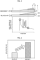
- Fig. 5 is a diagram comparing the peel stress between the joint structure of the related art and the joint structure of Embodiment 1.
- the horizontal axis thereof represents a position in the in-plane direction
- the vertical axis thereof represents the peel stress that is applied to the surface layer (the outermost layer of the inner surface).
- the joint structure of the related art includes the skin 5 and the stringer 6 and has a configuration in which the skin 5 corresponds to the plate portion 8 of Embodiment 1 and the stringer 6 corresponds to the reinforcement portion 9 of Embodiment 1. That is, in the joint structure of the related art, the stringer 6 which is a separate body corresponding to the reinforcement portion 9 is joined to the skin 5. In contrast, in the joint structure 1 of Embodiment 1, the stringer 6 configuring a part of the reinforcement portion 9 is joined to the skin 5 having the pad-up portion 10 configuring a part of the reinforcement portion 9.
- the first boundary which is the boundary between the skin 5 (the plate portion 8) and the reinforcement portion 9
- the second boundary which is the boundary between the skin 5 and the stringer 6
- the first boundary between the plate portion 8 and the reinforcement portion 9 (the pad-up portion 10 thereof) and the second boundary between the pad-up portion 10 and the flange portion 25 of the stringer 6 are located at different positions in the in-plane direction.
- the peel stress is concentrated on the first boundary between the skin 5 (the plate portion 8) and the reinforcement portion 9.
- the peel stress is a tensile stress in the out-of-plane direction. Therefore, in the joint structure of the related art, since the first boundary and the second boundary are located at the same position, a large peel stress is applied to the adhesive interface between the skin 5 and the stringer 6. On the other hand, in the joint structure 1 of Embodiment 1, since the first boundary and the second boundary are located at different positions, the peel stress that is applied to the adhesive interface between the skin 5 and the stringer 6 can be reduced compared to that in the related art.
- Fig. 6 is a diagram showing the joint strength performance in the joint structure of the related art and the joint structure of Embodiment 1.
- the vertical axis of Fig. 6 represents an initial fracture load in the joint structure 1 of the related art and the joint structure of Embodiment 1. If the peel stress at the adhesive interface is high, a fracture easily occurs in the adhesive interface, so that the joint strength is reduced and the initial fracture load of the joint structure 1 becomes a small value. That is, the larger the initial fracture load, the higher the joint strength performance becomes.
- the joint structure 1 of Embodiment 1 has an initial fracture load of about three times that of the joint structure of the related art, and improvement in the joint strength performance is confirmed.
- Fig. 7 is a graph showing the relationship between the plate thickness of the pad-up portion and the ease of peeling-off.
- the plate thickness of the pad-up portion 10 is set to be T 1
- the plate thickness of the flange portion 25 is set to be T 2 .
- the total plate thickness at the bonded portion is plate thickness T 1 +plate thickness T 2
- the vertical axis thereof represents a stress intensity factor of a crack tip of the bonded portion, which is a parameter relating to the ease of peeling-off.
- the horizontal axis thereof represents the pad thickness ratio PR.
- a change in stress intensity factor due to a change in the ratio of the plate thickness of the pad-up portion 10, that is, the sensitivity of the stress intensity factor is large in a case where the ratio of the plate thickness of the pad-up portion 10 is small, and is small in a case where the ratio of the plate thickness of the pad-up portion 10 is large.
- the first boundary and the second boundary can be located at different positions in the in-plane direction, the peel stress that is applied to the adhesive interface between the skin 5 and the stringer 6 can be reduced, whereby it is possible to improve the joint strength between the skin 5 and the stringer 6.
- the pad-up portion 10 is provided on the entire surface of the surface to be bonded, to which the stringer 6 is bonded, the flat surface of the pad-up portion 10, which serves as the surface to be bonded, and the bottom surface 28 of the flange portion 25 can be made to have a simple shape.
- the first inclined surface 21 and the second inclined surface 29 can form a continuous surface without a step, a change in shape at the second boundary can be suppressed, so that the concentration of the peel stress can be relaxed.
- the plate thickness T 1 of the pad-up portion 10 equal to or smaller than the plate thickness T 2 of the flange portion 25, it is possible to efficiently make a configuration in which the peeling-off is difficult due to a small change in the plate thickness of the pad-up portion 10.
- the joint structure 1 having a high joint strength between the skin 5 and the stringer 6 can be easily manufactured.
- Fig. 8 is a sectional view showing a laminated structure of the joint structure according to Embodiment 2.
- the flange portion 25 of the joint structure 1 of Embodiment 1 is bonded such that a part of the flat surface 22 of the pad-up portion 10 is exposed.
- the flange portion 25 is bonded to the pad-up portion 10 with being offset so as to be separated from the intersection portion of the first inclined surface 21 of the pad-up portion 10 and the flat surface 22 in the in-plane direction. Therefore, the pad-up portion 10 and the flange portion 25 form a stepped shape in which a step is formed.
- the flange portion 25 can be bonded to the flat surface 22 of the pad-up portion 10 in an offset state, it is possible to make the alignment between the pad-up portion 10 and the flange portion 25 easy, and it is possible to improve the efficiency of the bonding work. Further, since the position of the flange portion 25 can be offset with respect to the flat surface 22 of the pad-up portion 10, it becomes possible to absorb (allow) the assembly tolerance of the joint structure 1.
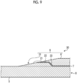
- a joint structure 30 according to Embodiment 3 will be described with reference to Fig. 9 .
- Fig. 9 is a sectional view schematically showing the joint structure according to Embodiment 3.
- the pad-up portion 10 of the joint structure 1 of Embodiment 1 is formed at the edge portion of the surface to be bonded, to which the stringer 6 is bonded.
- a pad-up portion 31 of the joint structure 30 is provided only at the portion on the tip side of the flange portion 25 to be bonded. Therefore, the region inside the pad-up portion 31 becomes the plate portion 8 in which the pad-up portion 31 is not integrally provided.
- the pad-up portion 31 has, for example, a trapezoidal cross section in which the height increases from the edge portion toward the central portion and then becomes flat and the height further decreases. Specifically, as shown in Fig.
- the pad-up portion 31 has the first inclined surface 21 that is formed on the edge portion (one side in the in-plane direction, that is, the left side in Fig. 9 ), the flat surface 22 that is connected to the first inclined surface 21, and a third inclined surface 33 that is formed on the other side in the in-plane direction (the right side in Fig. 9 ) and connected to the flat surface 22. Since the first inclined surface 21 and the flat surface 22 are substantially the same as those in Embodiment 1, the description thereof will be omitted.
- the third inclined surface 33 is an inclined surface that is a descending slope in which the plate thickness decreases from the flat surface 22 toward the other side in the in-plane direction.
- Embodiment 3 by forming the pad-up portion 31 only at the edge portion of the surface to be bonded, it is possible to increase the bonding area, and therefore, the joint strength between the skin 5 and the stringer 6 can be increased. Further, it becomes possible to secure the thickness of the flange portion 25 of the stringer 6 while reducing the peel stress.
- joint structure 1 or 30 and the method for manufacturing the joint structure 1 or 30 described in each embodiment are grasped as follows, for example.
- the joint structure 1 or 30 is the joint structure 1 or 30 including the reinforcement portion 9 which is formed by joining a composite material (the skin 5) and a reinforcing material (the stringer 6) through the adhesive 7, in which the composite material includes the plate portion 8 that is formed by laminating a plurality of fiber sheets S, and a raised portion (the pad-up portion 10) that is formed by further laminating the fiber sheets S with respect to the plate portion 8, the surfaces of the plate portion 8 and the raised portion are covered with the single fiber sheet Sa, the reinforcement portion 9 includes the raised portion and the reinforcing material that is bonded to the raised portion through the adhesive 7, and the first boundary between the plate portion 8 and the raised portion and the second boundary between the raised portion and the reinforcing material are located at different positions in the in-plane direction of the laminated interface between the fiber sheets S that are laminated.
- the first boundary and the second boundary can be located at different positions in the in-plane direction, the peel stress that is applied to the adhesive interface between the composite material and the reinforcing material can be reduced, whereby it is possible to improve the joint strength between the composite material and the reinforcing material.
- the raised portion is provided on an entire surface of a surface to be bonded where the reinforcing material is bonded to the composite material.
- the raised portion is provided on the entire surface of the surface to be bonded, to which the reinforcing material is bonded, the surfaces to be bonded of the raised portion and the reinforcing material can be made to have a simple shape.
- the raised portion is provided at an edge portion of a surface to be bonded where the reinforcing material is bonded to the composite material.
- the raised portion has the first inclined surface 21 that is an ascending slope from the first boundary toward the second boundary
- the reinforcing material has the second inclined surface 29 that is an ascending slope from the second boundary
- the raised portion and the reinforcing material are bonded to each other to form a surface in which the first inclined surface 21 and the second inclined surface 29 are connected to each other.
- the first inclined surface 21 and the second inclined surface 29 can form a continuous surface without a step, a change in shape at the second boundary can be suppressed, and therefore, the concentration of the peel stress can be relaxed.
- the raised portion has the first inclined surface 21 that is an ascending slope from the first boundary toward the second boundary, and the flat surface 22 extending in the in-plane direction parallel to the laminated interface between the fiber sheets from the second boundary, and the reinforcing material is bonded to the flat surface 22 with a part of the flat surface 22 of the raised portion exposed.
- the reinforcing material can be bonded to the raised portion in an offset state, it is possible to make the alignment between the raised portion and the reinforcing material easy, and it is possible to improve the efficiency of the bonding work.
- the thickness (plate thickness T 1 ) of the raised portion is equal to or smaller than the thickness (plate thickness T 2 ) of the portion of the reinforcing material, which is bonded to the raised portion.
- the thickness of the raised portion equal to or smaller than the thickness of the portion of the reinforcing material, it is possible to efficiently make a configuration in which the peeling-off is difficult due to a small change in the plate thickness of the raised portion.
- the method for manufacturing the joint structure 1 or 30 according to a seventh aspect includes: a step of molding a composite material which includes the plate portion 8 that is formed by laminating a plurality of fiber sheets S, and a raised portion that is formed by further laminating the fiber sheets S with respect to the plate portion 8, and in which surfaces of the plate portion 8 and the raised portion are covered with the single fiber sheet Sa; a step of molding a reinforcing material to be joined to the raised portion of the composite material; and a step of forming the joint structure 1 or 30 by joining the raised portion of the composite material and the reinforcing material through the adhesive 7.
Landscapes
- Engineering & Computer Science (AREA)
- Mechanical Engineering (AREA)
- Chemical & Material Sciences (AREA)
- Composite Materials (AREA)
- Aviation & Aerospace Engineering (AREA)
- Chemical Kinetics & Catalysis (AREA)
- General Chemical & Material Sciences (AREA)
- Moulding By Coating Moulds (AREA)
- Laminated Bodies (AREA)
- Lining Or Joining Of Plastics Or The Like (AREA)
Claims (7)
- Verbindungsstruktur (1), umfassend einen Verstärkungsabschnitt (9), der durch Verbinden eines Verbundmaterials (5) und eines Verstärkungsmaterials (6) durch einen Klebstoff (7) gebildet wird,wobei das Verbundmaterial (5) einen plattenförmigen Abschnitt (8), der durch Laminieren einer Vielzahl von Faserschichten (S) gebildet ist, und einen erhabenen Abschnitt (10, 31) einschließt, der durch Laminieren einer Vielzahl von Faserschichten (S) zusätzlich zu der Vielzahl von Faserschichten (S) des plattenförmigen Abschnitts (8) gebildet ist,wobei der Verstärkungsabschnitt (9) den erhabenen Abschnitt (10, 31) und das Verstärkungsmaterial (6) einschließt, das mit dem erhabenen Abschnitt (10, 31) durch einen Klebstoff (7) verbunden ist,wobei eine erste Grenze zwischen dem plattenförmigen Abschnitt (8) und dem erhabenen Abschnitt (10, 31) und eine zweite Grenze zwischen dem erhabenen Abschnitt (10, 31) und dem Verstärkungsmaterial (6) an verschiedenen Positionen in einer Richtung in der Ebene einer laminierten Grenzfläche zwischen den Faserschichten (S), die laminiert sind, angeordnet sind, unddadurch gekennzeichnet, dass die Flächen des plattenförmigen Abschnitts (8) und des erhabenen Abschnitts (10, 31) mit einer einzigen Faserschicht (5) bedeckt sind;wobei der plattenförmige Abschnitt (8) eine flache Platte ist, der erhabene Abschnitt (10) ein Abschnitt ist, der so gebildet ist, dass er in Bezug auf eine innere Fläche des plattenförmigen Abschnitts (8) erhaben ist, und auf einer gesamten Fläche einer zu verbindenden Fläche bereitgestellt ist, an die der Stringer (6) gebunden ist, und so konfiguriert ist, dass er eine auf die erste Grenze zwischen dem Verbundmaterial (5) und dem Verstärkungsmaterial (6) ausgeübte Schälspannung reduziert.
- Verbindungsstruktur (1) nach Anspruch 1, wobei der erhabene Abschnitt (10, 31) eine Fläche (22, 28) aufweist, auf der das Verstärkungsmaterial (6) mit dem Verbundmaterial (5) als Ganzes verbunden ist.
- Verbindungsstruktur (1) nach Anspruch 1, wobei der erhabene Abschnitt (31) an einem Randabschnitt einer zu verbindenden Fläche (22, 28) bereitgestellt ist, an der das Verstärkungsmaterial (6) mit dem Verbundmaterial (5) verbunden ist.
- Verbindungsstruktur (1) nach einem der Ansprüche 1 bis 3, wobei der erhabene Abschnitt (10, 31) eine erste geneigte Fläche (21) aufweist, die eine von der ersten Grenze zur zweiten Grenze hin ansteigende Steigung ist,wobei das Verstärkungsmaterial (6) eine zweite geneigte Fläche (29) aufweist, die eine von der zweiten Grenze aus ansteigende Steigung ist, undwobei der erhabene Abschnitt (10, 31) und das Verstärkungsmaterial (6) miteinander verbunden sind, um eine Fläche zu bilden, in der die erste geneigte Fläche (21) und die zweite geneigte Fläche (29) miteinander verbunden sind.
- Verbindungsstruktur (1) nach einem der Ansprüche 1 bis 3, wobei der erhabene Abschnitt (10, 31) eine erste geneigte Fläche (21) aufweist, die eine von der ersten Grenze zur zweiten Grenze hin ansteigende Steigung ist, und eine ebene Fläche, die sich in einer Richtung in der Ebene parallel zur laminierten Grenzfläche zwischen den Faserschichten (S) von der zweiten Grenze aus erstreckt, und
wobei das Verstärkungsmaterial (6) mit der flachen Fläche (22) verbunden ist, mit einem Teil der flachen Fläche (22) des erhabenen Abschnitts (10, 31) freiliegend. - Verbindungsstruktur (1) nach einem der Ansprüche 1 bis 5, wobei eine Dicke (T1) des erhabenen Abschnitts (10, 31) gleich oder kleiner ist als eine Dicke (T2) eines Abschnitts des Verstärkungsmaterials (6), der mit dem erhabenen Abschnitt (10, 31) verbunden ist.
- Verfahren zur Herstellung einer Verbindungsstruktur, umfassend:Formen eines Verbundmaterials, das einen plattenförmigen Abschnitt (8), der durch Laminieren einer Vielzahl von Faserschichten (S) gebildet wird, und einen erhabenen Abschnitt (10, 31) einschließt, der durch Laminieren einer Vielzahl von Faserschichten (S) zusätzlich zu der Vielzahl von Faserschichten (S) des plattenförmigen Abschnitts (8) gebildet wird, und bei dem die Flächen des plattenförmigen Abschnitts (8) und des erhabenen Abschnitts (10, 31) mit einer einzigen Faserschicht (S) bedeckt sind;Formen eines Verstärkungsmaterials (6), das mit dem erhabenen Abschnitt (10, 31) des Verbundmaterials (5) verbunden werden soll; undBilden einer Verbindungsstruktur (1) durch Verbinden des erhabenen Abschnitts (10, 31) des Verbundmaterials (5) und des Verstärkungsmaterials (6) durch einen Klebstoff (7),wobei beim Bilden der Verbindungsstruktur (1) eine zweite Grenze zwischen dem erhabenen Abschnitt (10, 31) und dem Verstärkungsmaterial (6) so eingestellt wird, dass sie sich in einer unterschiedlichen Position in Bezug auf eine erste Grenze zwischen dem plattenförmigen Abschnitt (8) und dem erhabenen Abschnitt (10, 31) in einer Richtung in der Ebene einer laminierten Grenzfläche zwischen den Faserschichten (5), die laminiert sind, befindet;dadurch gekennzeichnet, dassder plattenförmige Abschnitt (8) eine flache Platte ist, der erhabene Abschnitt (10) ein Abschnitt ist, der so gebildet ist, dass er in Bezug auf eine Innenfläche des plattenförmigen Abschnitts (8) erhaben ist, und auf einer gesamten Fläche einer zu verbindenden Fläche bereitgestellt ist, an die der Stringer (6) gebunden ist, und eine Schälspannung reduziert, die auf die erste Grenze zwischen dem Verbundmaterial (5) und dem Verstärkungsmaterial (6) ausgeübt wird.
Applications Claiming Priority (2)
| Application Number | Priority Date | Filing Date | Title |
|---|---|---|---|
| JP2020003164A JP7377722B2 (ja) | 2020-01-10 | 2020-01-10 | 接合構造体及び接合構造体の製造方法 |
| PCT/JP2020/047097 WO2021140861A1 (ja) | 2020-01-10 | 2020-12-17 | 接合構造体及び接合構造体の製造方法 |
Publications (3)
| Publication Number | Publication Date |
|---|---|
| EP4067066A1 EP4067066A1 (de) | 2022-10-05 |
| EP4067066A4 EP4067066A4 (de) | 2023-01-04 |
| EP4067066B1 true EP4067066B1 (de) | 2023-11-29 |
Family
ID=76787909
Family Applications (1)
| Application Number | Title | Priority Date | Filing Date |
|---|---|---|---|
| EP20911838.9A Active EP4067066B1 (de) | 2020-01-10 | 2020-12-17 | Verbindungsstruktur und verfahren zur herstellung einer verbindungsstruktur |
Country Status (4)
| Country | Link |
|---|---|
| US (1) | US12103244B2 (de) |
| EP (1) | EP4067066B1 (de) |
| JP (1) | JP7377722B2 (de) |
| WO (1) | WO2021140861A1 (de) |
Family Cites Families (7)
| Publication number | Priority date | Publication date | Assignee | Title |
|---|---|---|---|---|
| DE102007019716A1 (de) * | 2007-04-26 | 2008-10-30 | Airbus Deutschland Gmbh | Faser-Metall-Laminat-Panel |
| CA2768957C (en) * | 2009-10-08 | 2014-07-29 | Mitsubishi Heavy Industries, Ltd. | Composite-material structure and aircraft main wing and aircraft fuselage provided with the same |
| EP3152044A4 (de) * | 2014-06-04 | 2017-12-20 | Bright Lite Structures LlC | Verbundstruktur mit energieabsorption und/oder mit einer fehlerfreien oberfläche |
| US10421528B2 (en) | 2016-08-16 | 2019-09-24 | The Boeing Company | Planked stringers that provide structural support for an aircraft wing |
| US10442153B2 (en) * | 2017-12-22 | 2019-10-15 | The Boeing Company | Stiffened stringer panel with integral indexing laminate stacks |
| US10745104B2 (en) | 2018-03-02 | 2020-08-18 | The Boeing Company | Stringer transition through a common base charge |
| US11214349B2 (en) * | 2019-09-24 | 2022-01-04 | The Boeing Company | Stringers for aircraft skin structures and related methods |
-
2020
- 2020-01-10 JP JP2020003164A patent/JP7377722B2/ja active Active
- 2020-12-17 US US17/791,014 patent/US12103244B2/en active Active
- 2020-12-17 WO PCT/JP2020/047097 patent/WO2021140861A1/ja not_active Ceased
- 2020-12-17 EP EP20911838.9A patent/EP4067066B1/de active Active
Also Published As
| Publication number | Publication date |
|---|---|
| JP2021109389A (ja) | 2021-08-02 |
| EP4067066A1 (de) | 2022-10-05 |
| EP4067066A4 (de) | 2023-01-04 |
| JP7377722B2 (ja) | 2023-11-10 |
| WO2021140861A1 (ja) | 2021-07-15 |
| US20230016964A1 (en) | 2023-01-19 |
| US12103244B2 (en) | 2024-10-01 |
Similar Documents
| Publication | Publication Date | Title |
|---|---|---|
| EP2487106B1 (de) | Verbundstoffmaterialstruktur, sowie flugzeugtragfläche und damit ausgestatteter flugzeugrumpf | |
| EP2651759B1 (de) | Schrägwinkeliger radiusfüller zur verringerung des risikos einer delamination einer laminierten stringeranordnung | |
| EP2727821B1 (de) | Umfangsverbinder für Schalenstrukturen | |
| RU2501710C2 (ru) | Система и способ для формирования подкрепляющего элемента за одно целое с многослойным металловолокнистым листом | |
| KR101513845B1 (ko) | 패널의 리세스에 삽입된 패드를 갖는 스트링거를 포함하는 복합 구조체 및 힘 전달 방법 | |
| US7285326B2 (en) | Lightweight structure particularly for an aircraft | |
| CN101842539A (zh) | 加强复合面板 | |
| US8777159B2 (en) | Internal structure of aircraft made of composite material | |
| CN104053596B (zh) | 结构组件以及用于将第一部件紧固至第二部件的方法 | |
| KR20130139929A (ko) | 보강재 런-아웃 | |
| US10040538B2 (en) | Joint, and aircraft structure | |
| CN102186722B (zh) | 用于增强飞机机身的结构元件 | |
| US9034453B2 (en) | Reinforced aircraft fuselage panel and method of manufacture | |
| JP2012162147A (ja) | 複合材構造体、これを備えた航空機主翼および航空機胴体 | |
| EP3666504B1 (de) | Verbindungsstruktur | |
| CN111746778A (zh) | 用于飞行器的加强结构部件 | |
| US7100871B2 (en) | Lightweight structural component made of metallic ply materials | |
| JP7236337B2 (ja) | 複合材翼及び複合材翼の成形方法 | |
| US12103244B2 (en) | Joint structure and method for manufacturing joint structure | |
| EP2669185B1 (de) | Sicherungsplatte und Flugzeugstruktur |
Legal Events
| Date | Code | Title | Description |
|---|---|---|---|
| STAA | Information on the status of an ep patent application or granted ep patent |
Free format text: STATUS: THE INTERNATIONAL PUBLICATION HAS BEEN MADE |
|
| PUAI | Public reference made under article 153(3) epc to a published international application that has entered the european phase |
Free format text: ORIGINAL CODE: 0009012 |
|
| STAA | Information on the status of an ep patent application or granted ep patent |
Free format text: STATUS: REQUEST FOR EXAMINATION WAS MADE |
|
| 17P | Request for examination filed |
Effective date: 20220630 |
|
| AK | Designated contracting states |
Kind code of ref document: A1 Designated state(s): AL AT BE BG CH CY CZ DE DK EE ES FI FR GB GR HR HU IE IS IT LI LT LU LV MC MK MT NL NO PL PT RO RS SE SI SK SM TR |
|
| A4 | Supplementary search report drawn up and despatched |
Effective date: 20221205 |
|
| RIC1 | Information provided on ipc code assigned before grant |
Ipc: B32B 5/26 20060101ALI20221129BHEP Ipc: B32B 3/08 20060101ALI20221129BHEP Ipc: B64C 1/00 20060101ALI20221129BHEP Ipc: B32B 3/30 20060101ALI20221129BHEP Ipc: B32B 3/02 20060101ALI20221129BHEP Ipc: B29C 65/48 20060101ALI20221129BHEP Ipc: B32B 5/28 20060101AFI20221129BHEP |
|
| DAV | Request for validation of the european patent (deleted) | ||
| DAX | Request for extension of the european patent (deleted) | ||
| GRAP | Despatch of communication of intention to grant a patent |
Free format text: ORIGINAL CODE: EPIDOSNIGR1 |
|
| STAA | Information on the status of an ep patent application or granted ep patent |
Free format text: STATUS: GRANT OF PATENT IS INTENDED |
|
| INTG | Intention to grant announced |
Effective date: 20230726 |
|
| GRAS | Grant fee paid |
Free format text: ORIGINAL CODE: EPIDOSNIGR3 |
|
| GRAA | (expected) grant |
Free format text: ORIGINAL CODE: 0009210 |
|
| STAA | Information on the status of an ep patent application or granted ep patent |
Free format text: STATUS: THE PATENT HAS BEEN GRANTED |
|
| AK | Designated contracting states |
Kind code of ref document: B1 Designated state(s): AL AT BE BG CH CY CZ DE DK EE ES FI FR GB GR HR HU IE IS IT LI LT LU LV MC MK MT NL NO PL PT RO RS SE SI SK SM TR |
|
| REG | Reference to a national code |
Ref country code: GB Ref legal event code: FG4D |
|
| REG | Reference to a national code |
Ref country code: CH Ref legal event code: EP |
|
| REG | Reference to a national code |
Ref country code: DE Ref legal event code: R096 Ref document number: 602020022123 Country of ref document: DE |
|
| REG | Reference to a national code |
Ref country code: IE Ref legal event code: FG4D |
|
| REG | Reference to a national code |
Ref country code: LT Ref legal event code: MG9D |
|
| REG | Reference to a national code |
Ref country code: NL Ref legal event code: MP Effective date: 20231129 |
|
| PG25 | Lapsed in a contracting state [announced via postgrant information from national office to epo] |
Ref country code: GR Free format text: LAPSE BECAUSE OF FAILURE TO SUBMIT A TRANSLATION OF THE DESCRIPTION OR TO PAY THE FEE WITHIN THE PRESCRIBED TIME-LIMIT Effective date: 20240301 |
|
| PG25 | Lapsed in a contracting state [announced via postgrant information from national office to epo] |
Ref country code: IS Free format text: LAPSE BECAUSE OF FAILURE TO SUBMIT A TRANSLATION OF THE DESCRIPTION OR TO PAY THE FEE WITHIN THE PRESCRIBED TIME-LIMIT Effective date: 20240329 |
|
| PG25 | Lapsed in a contracting state [announced via postgrant information from national office to epo] |
Ref country code: LT Free format text: LAPSE BECAUSE OF FAILURE TO SUBMIT A TRANSLATION OF THE DESCRIPTION OR TO PAY THE FEE WITHIN THE PRESCRIBED TIME-LIMIT Effective date: 20231129 |
|
| PG25 | Lapsed in a contracting state [announced via postgrant information from national office to epo] |
Ref country code: ES Free format text: LAPSE BECAUSE OF FAILURE TO SUBMIT A TRANSLATION OF THE DESCRIPTION OR TO PAY THE FEE WITHIN THE PRESCRIBED TIME-LIMIT Effective date: 20231129 |
|
| PG25 | Lapsed in a contracting state [announced via postgrant information from national office to epo] |
Ref country code: LT Free format text: LAPSE BECAUSE OF FAILURE TO SUBMIT A TRANSLATION OF THE DESCRIPTION OR TO PAY THE FEE WITHIN THE PRESCRIBED TIME-LIMIT Effective date: 20231129 Ref country code: IS Free format text: LAPSE BECAUSE OF FAILURE TO SUBMIT A TRANSLATION OF THE DESCRIPTION OR TO PAY THE FEE WITHIN THE PRESCRIBED TIME-LIMIT Effective date: 20240329 Ref country code: GR Free format text: LAPSE BECAUSE OF FAILURE TO SUBMIT A TRANSLATION OF THE DESCRIPTION OR TO PAY THE FEE WITHIN THE PRESCRIBED TIME-LIMIT Effective date: 20240301 Ref country code: ES Free format text: LAPSE BECAUSE OF FAILURE TO SUBMIT A TRANSLATION OF THE DESCRIPTION OR TO PAY THE FEE WITHIN THE PRESCRIBED TIME-LIMIT Effective date: 20231129 Ref country code: BG Free format text: LAPSE BECAUSE OF FAILURE TO SUBMIT A TRANSLATION OF THE DESCRIPTION OR TO PAY THE FEE WITHIN THE PRESCRIBED TIME-LIMIT Effective date: 20240229 |
|
| REG | Reference to a national code |
Ref country code: AT Ref legal event code: MK05 Ref document number: 1635721 Country of ref document: AT Kind code of ref document: T Effective date: 20231129 |
|
| PG25 | Lapsed in a contracting state [announced via postgrant information from national office to epo] |
Ref country code: NL Free format text: LAPSE BECAUSE OF FAILURE TO SUBMIT A TRANSLATION OF THE DESCRIPTION OR TO PAY THE FEE WITHIN THE PRESCRIBED TIME-LIMIT Effective date: 20231129 |
|
| PG25 | Lapsed in a contracting state [announced via postgrant information from national office to epo] |
Ref country code: SE Free format text: LAPSE BECAUSE OF FAILURE TO SUBMIT A TRANSLATION OF THE DESCRIPTION OR TO PAY THE FEE WITHIN THE PRESCRIBED TIME-LIMIT Effective date: 20231129 Ref country code: RS Free format text: LAPSE BECAUSE OF FAILURE TO SUBMIT A TRANSLATION OF THE DESCRIPTION OR TO PAY THE FEE WITHIN THE PRESCRIBED TIME-LIMIT Effective date: 20231129 Ref country code: PL Free format text: LAPSE BECAUSE OF FAILURE TO SUBMIT A TRANSLATION OF THE DESCRIPTION OR TO PAY THE FEE WITHIN THE PRESCRIBED TIME-LIMIT Effective date: 20231129 Ref country code: NO Free format text: LAPSE BECAUSE OF FAILURE TO SUBMIT A TRANSLATION OF THE DESCRIPTION OR TO PAY THE FEE WITHIN THE PRESCRIBED TIME-LIMIT Effective date: 20240229 Ref country code: NL Free format text: LAPSE BECAUSE OF FAILURE TO SUBMIT A TRANSLATION OF THE DESCRIPTION OR TO PAY THE FEE WITHIN THE PRESCRIBED TIME-LIMIT Effective date: 20231129 Ref country code: LV Free format text: LAPSE BECAUSE OF FAILURE TO SUBMIT A TRANSLATION OF THE DESCRIPTION OR TO PAY THE FEE WITHIN THE PRESCRIBED TIME-LIMIT Effective date: 20231129 Ref country code: HR Free format text: LAPSE BECAUSE OF FAILURE TO SUBMIT A TRANSLATION OF THE DESCRIPTION OR TO PAY THE FEE WITHIN THE PRESCRIBED TIME-LIMIT Effective date: 20231129 |
|
| REG | Reference to a national code |
Ref country code: DE Ref legal event code: R119 Ref document number: 602020022123 Country of ref document: DE |
|
| PG25 | Lapsed in a contracting state [announced via postgrant information from national office to epo] |
Ref country code: DK Free format text: LAPSE BECAUSE OF FAILURE TO SUBMIT A TRANSLATION OF THE DESCRIPTION OR TO PAY THE FEE WITHIN THE PRESCRIBED TIME-LIMIT Effective date: 20231129 |
|
| PG25 | Lapsed in a contracting state [announced via postgrant information from national office to epo] |
Ref country code: CZ Free format text: LAPSE BECAUSE OF FAILURE TO SUBMIT A TRANSLATION OF THE DESCRIPTION OR TO PAY THE FEE WITHIN THE PRESCRIBED TIME-LIMIT Effective date: 20231129 Ref country code: AT Free format text: LAPSE BECAUSE OF FAILURE TO SUBMIT A TRANSLATION OF THE DESCRIPTION OR TO PAY THE FEE WITHIN THE PRESCRIBED TIME-LIMIT Effective date: 20231129 |
|
| PG25 | Lapsed in a contracting state [announced via postgrant information from national office to epo] |
Ref country code: SK Free format text: LAPSE BECAUSE OF FAILURE TO SUBMIT A TRANSLATION OF THE DESCRIPTION OR TO PAY THE FEE WITHIN THE PRESCRIBED TIME-LIMIT Effective date: 20231129 |
|
| PG25 | Lapsed in a contracting state [announced via postgrant information from national office to epo] |
Ref country code: SM Free format text: LAPSE BECAUSE OF FAILURE TO SUBMIT A TRANSLATION OF THE DESCRIPTION OR TO PAY THE FEE WITHIN THE PRESCRIBED TIME-LIMIT Effective date: 20231129 Ref country code: SK Free format text: LAPSE BECAUSE OF FAILURE TO SUBMIT A TRANSLATION OF THE DESCRIPTION OR TO PAY THE FEE WITHIN THE PRESCRIBED TIME-LIMIT Effective date: 20231129 Ref country code: RO Free format text: LAPSE BECAUSE OF FAILURE TO SUBMIT A TRANSLATION OF THE DESCRIPTION OR TO PAY THE FEE WITHIN THE PRESCRIBED TIME-LIMIT Effective date: 20231129 Ref country code: IT Free format text: LAPSE BECAUSE OF NON-PAYMENT OF DUE FEES Effective date: 20231217 Ref country code: EE Free format text: LAPSE BECAUSE OF FAILURE TO SUBMIT A TRANSLATION OF THE DESCRIPTION OR TO PAY THE FEE WITHIN THE PRESCRIBED TIME-LIMIT Effective date: 20231129 Ref country code: DK Free format text: LAPSE BECAUSE OF FAILURE TO SUBMIT A TRANSLATION OF THE DESCRIPTION OR TO PAY THE FEE WITHIN THE PRESCRIBED TIME-LIMIT Effective date: 20231129 Ref country code: CZ Free format text: LAPSE BECAUSE OF FAILURE TO SUBMIT A TRANSLATION OF THE DESCRIPTION OR TO PAY THE FEE WITHIN THE PRESCRIBED TIME-LIMIT Effective date: 20231129 Ref country code: AT Free format text: LAPSE BECAUSE OF FAILURE TO SUBMIT A TRANSLATION OF THE DESCRIPTION OR TO PAY THE FEE WITHIN THE PRESCRIBED TIME-LIMIT Effective date: 20231129 |
|
| REG | Reference to a national code |
Ref country code: CH Ref legal event code: PL |
|
| PG25 | Lapsed in a contracting state [announced via postgrant information from national office to epo] |
Ref country code: PT Free format text: LAPSE BECAUSE OF FAILURE TO SUBMIT A TRANSLATION OF THE DESCRIPTION OR TO PAY THE FEE WITHIN THE PRESCRIBED TIME-LIMIT Effective date: 20240401 |
|
| PG25 | Lapsed in a contracting state [announced via postgrant information from national office to epo] |
Ref country code: LU Free format text: LAPSE BECAUSE OF NON-PAYMENT OF DUE FEES Effective date: 20231217 |
|
| PG25 | Lapsed in a contracting state [announced via postgrant information from national office to epo] |
Ref country code: MC Free format text: LAPSE BECAUSE OF FAILURE TO SUBMIT A TRANSLATION OF THE DESCRIPTION OR TO PAY THE FEE WITHIN THE PRESCRIBED TIME-LIMIT Effective date: 20231129 |
|
| REG | Reference to a national code |
Ref country code: BE Ref legal event code: MM Effective date: 20231231 |
|
| PG25 | Lapsed in a contracting state [announced via postgrant information from national office to epo] |
Ref country code: PT Free format text: LAPSE BECAUSE OF FAILURE TO SUBMIT A TRANSLATION OF THE DESCRIPTION OR TO PAY THE FEE WITHIN THE PRESCRIBED TIME-LIMIT Effective date: 20240401 Ref country code: MC Free format text: LAPSE BECAUSE OF FAILURE TO SUBMIT A TRANSLATION OF THE DESCRIPTION OR TO PAY THE FEE WITHIN THE PRESCRIBED TIME-LIMIT Effective date: 20231129 Ref country code: LU Free format text: LAPSE BECAUSE OF NON-PAYMENT OF DUE FEES Effective date: 20231217 |
|
| PLBE | No opposition filed within time limit |
Free format text: ORIGINAL CODE: 0009261 |
|
| STAA | Information on the status of an ep patent application or granted ep patent |
Free format text: STATUS: NO OPPOSITION FILED WITHIN TIME LIMIT |
|
| REG | Reference to a national code |
Ref country code: IE Ref legal event code: MM4A |
|
| PG25 | Lapsed in a contracting state [announced via postgrant information from national office to epo] |
Ref country code: DE Free format text: LAPSE BECAUSE OF NON-PAYMENT OF DUE FEES Effective date: 20240702 Ref country code: IE Free format text: LAPSE BECAUSE OF NON-PAYMENT OF DUE FEES Effective date: 20231217 |
|
| PG25 | Lapsed in a contracting state [announced via postgrant information from national office to epo] |
Ref country code: BE Free format text: LAPSE BECAUSE OF NON-PAYMENT OF DUE FEES Effective date: 20231231 |
|
| PG25 | Lapsed in a contracting state [announced via postgrant information from national office to epo] |
Ref country code: CH Free format text: LAPSE BECAUSE OF NON-PAYMENT OF DUE FEES Effective date: 20231231 |
|
| PG25 | Lapsed in a contracting state [announced via postgrant information from national office to epo] |
Ref country code: SI Free format text: LAPSE BECAUSE OF FAILURE TO SUBMIT A TRANSLATION OF THE DESCRIPTION OR TO PAY THE FEE WITHIN THE PRESCRIBED TIME-LIMIT Effective date: 20231129 |
|
| PG25 | Lapsed in a contracting state [announced via postgrant information from national office to epo] |
Ref country code: SI Free format text: LAPSE BECAUSE OF FAILURE TO SUBMIT A TRANSLATION OF THE DESCRIPTION OR TO PAY THE FEE WITHIN THE PRESCRIBED TIME-LIMIT Effective date: 20231129 Ref country code: IE Free format text: LAPSE BECAUSE OF NON-PAYMENT OF DUE FEES Effective date: 20231217 Ref country code: DE Free format text: LAPSE BECAUSE OF NON-PAYMENT OF DUE FEES Effective date: 20240702 Ref country code: CH Free format text: LAPSE BECAUSE OF NON-PAYMENT OF DUE FEES Effective date: 20231231 Ref country code: BE Free format text: LAPSE BECAUSE OF NON-PAYMENT OF DUE FEES Effective date: 20231231 |
|
| 26N | No opposition filed |
Effective date: 20240830 |
|
| PG25 | Lapsed in a contracting state [announced via postgrant information from national office to epo] |
Ref country code: IT Free format text: LAPSE BECAUSE OF NON-PAYMENT OF DUE FEES Effective date: 20231217 |
|
| PGRI | Patent reinstated in contracting state [announced from national office to epo] |
Ref country code: IT Effective date: 20240102 |
|
| PG25 | Lapsed in a contracting state [announced via postgrant information from national office to epo] |
Ref country code: FI Free format text: LAPSE BECAUSE OF FAILURE TO SUBMIT A TRANSLATION OF THE DESCRIPTION OR TO PAY THE FEE WITHIN THE PRESCRIBED TIME-LIMIT Effective date: 20231129 |
|
| PG25 | Lapsed in a contracting state [announced via postgrant information from national office to epo] |
Ref country code: CY Free format text: LAPSE BECAUSE OF FAILURE TO SUBMIT A TRANSLATION OF THE DESCRIPTION OR TO PAY THE FEE WITHIN THE PRESCRIBED TIME-LIMIT; INVALID AB INITIO Effective date: 20201217 |
|
| PG25 | Lapsed in a contracting state [announced via postgrant information from national office to epo] |
Ref country code: HU Free format text: LAPSE BECAUSE OF FAILURE TO SUBMIT A TRANSLATION OF THE DESCRIPTION OR TO PAY THE FEE WITHIN THE PRESCRIBED TIME-LIMIT; INVALID AB INITIO Effective date: 20201217 |
|
| PG25 | Lapsed in a contracting state [announced via postgrant information from national office to epo] |
Ref country code: TR Free format text: LAPSE BECAUSE OF FAILURE TO SUBMIT A TRANSLATION OF THE DESCRIPTION OR TO PAY THE FEE WITHIN THE PRESCRIBED TIME-LIMIT Effective date: 20231129 |
|
| PGFP | Annual fee paid to national office [announced via postgrant information from national office to epo] |
Ref country code: GB Payment date: 20251030 Year of fee payment: 6 |
|
| PGFP | Annual fee paid to national office [announced via postgrant information from national office to epo] |
Ref country code: IT Payment date: 20251121 Year of fee payment: 6 |
|
| PGFP | Annual fee paid to national office [announced via postgrant information from national office to epo] |
Ref country code: FR Payment date: 20251110 Year of fee payment: 6 |