EP3029338B1 - Valve actuator device with driving arm having a modular structure - Google Patents
Valve actuator device with driving arm having a modular structure Download PDFInfo
- Publication number
- EP3029338B1 EP3029338B1 EP15196317.0A EP15196317A EP3029338B1 EP 3029338 B1 EP3029338 B1 EP 3029338B1 EP 15196317 A EP15196317 A EP 15196317A EP 3029338 B1 EP3029338 B1 EP 3029338B1
- Authority
- EP
- European Patent Office
- Prior art keywords
- slot
- actuator device
- valve actuator
- driving arm
- insert
- Prior art date
- Legal status (The legal status is an assumption and is not a legal conclusion. Google has not performed a legal analysis and makes no representation as to the accuracy of the status listed.)
- Active
Links
Images


Classifications
-
- F—MECHANICAL ENGINEERING; LIGHTING; HEATING; WEAPONS; BLASTING
- F15—FLUID-PRESSURE ACTUATORS; HYDRAULICS OR PNEUMATICS IN GENERAL
- F15B—SYSTEMS ACTING BY MEANS OF FLUIDS IN GENERAL; FLUID-PRESSURE ACTUATORS, e.g. SERVOMOTORS; DETAILS OF FLUID-PRESSURE SYSTEMS, NOT OTHERWISE PROVIDED FOR
- F15B15/00—Fluid-actuated devices for displacing a member from one position to another; Gearing associated therewith
- F15B15/02—Mechanical layout characterised by the means for converting the movement of the fluid-actuated element into movement of the finally-operated member
- F15B15/06—Mechanical layout characterised by the means for converting the movement of the fluid-actuated element into movement of the finally-operated member for mechanically converting rectilinear movement into non- rectilinear movement
- F15B15/066—Mechanical layout characterised by the means for converting the movement of the fluid-actuated element into movement of the finally-operated member for mechanically converting rectilinear movement into non- rectilinear movement the motor being of the scotch yoke type
-
- F—MECHANICAL ENGINEERING; LIGHTING; HEATING; WEAPONS; BLASTING
- F16—ENGINEERING ELEMENTS AND UNITS; GENERAL MEASURES FOR PRODUCING AND MAINTAINING EFFECTIVE FUNCTIONING OF MACHINES OR INSTALLATIONS; THERMAL INSULATION IN GENERAL
- F16K—VALVES; TAPS; COCKS; ACTUATING-FLOATS; DEVICES FOR VENTING OR AERATING
- F16K31/00—Actuating devices; Operating means; Releasing devices
- F16K31/12—Actuating devices; Operating means; Releasing devices actuated by fluid
- F16K31/14—Actuating devices; Operating means; Releasing devices actuated by fluid for mounting on, or in combination with, hand-actuated valves
- F16K31/143—Actuating devices; Operating means; Releasing devices actuated by fluid for mounting on, or in combination with, hand-actuated valves the fluid acting on a piston
-
- F—MECHANICAL ENGINEERING; LIGHTING; HEATING; WEAPONS; BLASTING
- F16—ENGINEERING ELEMENTS AND UNITS; GENERAL MEASURES FOR PRODUCING AND MAINTAINING EFFECTIVE FUNCTIONING OF MACHINES OR INSTALLATIONS; THERMAL INSULATION IN GENERAL
- F16K—VALVES; TAPS; COCKS; ACTUATING-FLOATS; DEVICES FOR VENTING OR AERATING
- F16K31/00—Actuating devices; Operating means; Releasing devices
- F16K31/12—Actuating devices; Operating means; Releasing devices actuated by fluid
- F16K31/36—Actuating devices; Operating means; Releasing devices actuated by fluid in which fluid from the circuit is constantly supplied to the fluid motor
- F16K31/363—Actuating devices; Operating means; Releasing devices actuated by fluid in which fluid from the circuit is constantly supplied to the fluid motor the fluid acting on a piston
-
- F—MECHANICAL ENGINEERING; LIGHTING; HEATING; WEAPONS; BLASTING
- F15—FLUID-PRESSURE ACTUATORS; HYDRAULICS OR PNEUMATICS IN GENERAL
- F15B—SYSTEMS ACTING BY MEANS OF FLUIDS IN GENERAL; FLUID-PRESSURE ACTUATORS, e.g. SERVOMOTORS; DETAILS OF FLUID-PRESSURE SYSTEMS, NOT OTHERWISE PROVIDED FOR
- F15B15/00—Fluid-actuated devices for displacing a member from one position to another; Gearing associated therewith
- F15B15/02—Mechanical layout characterised by the means for converting the movement of the fluid-actuated element into movement of the finally-operated member
- F15B15/06—Mechanical layout characterised by the means for converting the movement of the fluid-actuated element into movement of the finally-operated member for mechanically converting rectilinear movement into non- rectilinear movement
-
- F—MECHANICAL ENGINEERING; LIGHTING; HEATING; WEAPONS; BLASTING
- F15—FLUID-PRESSURE ACTUATORS; HYDRAULICS OR PNEUMATICS IN GENERAL
- F15B—SYSTEMS ACTING BY MEANS OF FLUIDS IN GENERAL; FLUID-PRESSURE ACTUATORS, e.g. SERVOMOTORS; DETAILS OF FLUID-PRESSURE SYSTEMS, NOT OTHERWISE PROVIDED FOR
- F15B15/00—Fluid-actuated devices for displacing a member from one position to another; Gearing associated therewith
- F15B15/20—Other details, e.g. assembly with regulating devices
- F15B15/22—Other details, e.g. assembly with regulating devices for accelerating or decelerating the stroke
- F15B15/226—Other details, e.g. assembly with regulating devices for accelerating or decelerating the stroke having elastic elements, e.g. springs, rubber pads
-
- F—MECHANICAL ENGINEERING; LIGHTING; HEATING; WEAPONS; BLASTING
- F16—ENGINEERING ELEMENTS AND UNITS; GENERAL MEASURES FOR PRODUCING AND MAINTAINING EFFECTIVE FUNCTIONING OF MACHINES OR INSTALLATIONS; THERMAL INSULATION IN GENERAL
- F16K—VALVES; TAPS; COCKS; ACTUATING-FLOATS; DEVICES FOR VENTING OR AERATING
- F16K31/00—Actuating devices; Operating means; Releasing devices
- F16K31/12—Actuating devices; Operating means; Releasing devices actuated by fluid
- F16K31/14—Actuating devices; Operating means; Releasing devices actuated by fluid for mounting on, or in combination with, hand-actuated valves
-
- F—MECHANICAL ENGINEERING; LIGHTING; HEATING; WEAPONS; BLASTING
- F16—ENGINEERING ELEMENTS AND UNITS; GENERAL MEASURES FOR PRODUCING AND MAINTAINING EFFECTIVE FUNCTIONING OF MACHINES OR INSTALLATIONS; THERMAL INSULATION IN GENERAL
- F16K—VALVES; TAPS; COCKS; ACTUATING-FLOATS; DEVICES FOR VENTING OR AERATING
- F16K31/00—Actuating devices; Operating means; Releasing devices
- F16K31/12—Actuating devices; Operating means; Releasing devices actuated by fluid
- F16K31/36—Actuating devices; Operating means; Releasing devices actuated by fluid in which fluid from the circuit is constantly supplied to the fluid motor
Definitions
- the present invention relates to valve actuator devices, of the type comprising:
- Devices of this type frequently, but not necessarily always, comprise also a fail-safe safety device for recalling said driving arm towards a safety position corresponding to one of the said end operating positions, said safety device comprising a casing fixed to said supporting body on a side opposite to said fluid cylinder and having an axis parallel to the axis of the fluid cylinder, a piston disk slidably mounted within said casing, a rod connected to said piston disk and connected to said cam-follower member, and a helical spring contained in said casing and tending to recall the driving arm towards said safety position.
- Actuator devices of this sort are used for controlling valves of various kinds, in particular large-sized valves, in systems of various types.
- the actuator is able to control the movable member of the valve between a complete closed condition and a complete opened conditionenabling in certain cases also modulation of the flow rate of fluid through the valve, positioning the movable member of the valve in an intermediate position between its two end positions.
- the driving shaft of the actuator performs a rotation of 90° for displacing the movable member of the valve between its opened and closed positions.
- An actuator device of the type referred to above and according to the preamble of claim 1 is for example disclosed in US-A-4 350 081 .
- the driving torque that the actuator device is able to apply to the aforesaid valve driving shaft depends upon the force applied by the fluid cylinder to the driving arm (via engagement of the cam-follower member within the respective slot); this torque also depends upon the geometrical distance of the effective component of this force from the axis of the driving shaft.
- Each specific application requires in general a specific design of the actuator device in order to obtain desired values of the driving torque as a function of the angle of rotation of the driving arm.
- Each specific actuator device is hence characterized by a specific torque curve, i.e., by a specific variation of the driving torque as a function of the angle of rotation of the driving arm.
- the maximum and minimum driving torques that can be obtained are necessarily linked to the dimensions of the device and in particular to the distance of the axis of the driving shaft from the axis of the fluid cylinder (which is the "theoretical" lever arm), whereas it would be desirable to be able to modify the effective lever arm of the device with respect to the axis of the driving shaft, without modifying the overall dimensions of the device.
- the object of the present invention is to provide an actuator device of the above indicated type that is adapted in general to be used in different applications which have requirements which may be very different from each other in relation to the driving torque to be applied and/or to the stresses to be withstood.
- a particular object of the invention is to provide an actuator device that can be adapted with simple and quick operations to any specific applications, in such a way as to present any desired profile of the curve of the driving torque.
- a further object of the invention is to enable the effective lever arm of the device with respect to the axis of the driving shaft to be changed, without modifying the overall dimensions of the device.
- the subject of the invention is a valve actuator device having all the characteristics that have been specified at the start of the present description and further characterized in that the aforesaid slot of the driving arm is formed in an insert constituting a separate element from the body of the aforesaid driving arm and adapted to be received and held in a seat of the body of the driving arm.
- valve actuator according to the invention can be produced according to a modularity concept, by providing one and the same basic body for the driving arm and assembling thereon an insert each time selected from among a plurality of different inserts, so as to respond easily and quickly to the specific requirements of any individual application.
- a plurality of inserts are provided in association to the actuator device, which can be selectively mounted on the driving arm, said inserts being different from each other in one or more of the following characteristics:
- the modular structure described above further enables a considerable reduction in the production costs, a standardization of the production, and preparation in a short time of a best configuration of the actuator according to the requirements of application. Finally, also the operations of maintenance are facilitated in so far as the parts subject to wear are easier and cheaper to replace. In particular, it is possible to replace only the aforesaid insert instead of the entire driving arm.
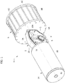
- number 1 designates as a whole a valve-actuator device according to the present invention.
- the device 1 comprises a central supporting body 2 in the form of a metal casing constituted by an element 2A, screwed on which is a lid (not illustrated) to define a closed internal cavity 3.
- Figure 1 shows just one of the two elements 2A constituting the supporting body 2 in order to render visible the parts arranged within the cavity 3.
- the central supporting body 2 supports a driving shaft 5 in rotation around a main axis 4.
- the driving shaft 5 is made in the form of an internally grooved bushing for receiving within it a driving rod (not illustrated) of the movable member of a valve.
- the bushing constituting the driving shaft 5 is rotatably mounted within the supporting body 2 by means of sliding or rolling bearings of any known type.
- the actuator device controls rotation of the driving shaft 5, which in turn governs rotation of the movable member of the valve between a completely closed position and a completely open position.
- the movable member of the valve may, for example, be of the type in which passage from the open position to the closed position of the valve occurs with a rotation of 90° around the main axis 4.
- the example of embodiment illustrated herein regards an application with a rotation of from 0° to 90° (a quarter of a turn), with a tolerance of approximately 10° on the end values.
- the principle that underlies the invention is of general application.
- the actuator device according to the invention may be used both for displacing the movable member of a valve between the position of complete opening and the position of complete closing, and possibly also, for the applications where this is required, for positioning the movable member of the valve in any intermediate position.
- the fluid cylinder 6 may be either a hydraulic cylinder or a pneumatic cylinder.
- the example illustrated regards in particular the case of a pneumatic cylinder.
- the cylinder 6 comprises a cylinder body having an axis 6X.
- the axis 6X of the cylinder 6 and the axis 4 of the driving shaft 5 are not incident with respect to one another, but are contained in mutually orthogonal planes.
- the cylinder body is defined by a cylindrical wall 6B closed at one end by the aforesaid end plate 6A and at the opposite end by an end plate 6C.
- the end plates 6A, 6C are held against the opposite ends of the cylindrical wall 6B by a plurality of screw-operated tie rods 6D.
- a piston 7 rigidly connected to a rod 8 that is slidably mounted through a central opening of the end plate 6a and through a hole 9 of a side wall of the supporting body 2. Consequently, the rod 8 extends into the cavity 3 of the supporting body 2.
- the rod 8 of the fluid cylinder 6 is designed to govern rotation of the driving shaft 5 by means of a pin-slot transmission, which enables conversion of the linear movement of the rod 8 into a rotation of the driving shaft 5 around the axis 4.
- a driving arm 10 rigidly connected on the driving shaft 5 is a driving arm 10 carrying a cam track in the form of a slot 11 engaged by a cam-follower pin 12 carried by the rod 8.
- the slot 11 is formed in an insert 20 assembled on the body of the driving arm 10.
- the driving arm 10 has a yoke conformation, with two plates 10A parallel and set apart from one another (see Figures 3 and 4 ), just one of which is visible in Figures 1 and 2 .
- each of the plates 10A has an elongated ellipsoidal conformation, with one end rigidly connected on the driving shaft 5.
- the remaining part of the body of each plate 10A has a respective slot 11.
- the slot 11 is formed in an insert 20 assembled on each plate 10A.
- the slots 11 provided on the two plates 10A are identical to one another and identically positioned. These slots 11 are engaged by the ends of the cam-follower pin 12 (see in particular Figure 4 ) that is carried by a block 13 rigidly connected to the rod 8.
- the pin 12 projects on opposite sides of the block 13 to engage the slots 11 provided in the plates 10A.
- the two plates 10A constitute together the driving arm of the actuator device. Engagement of the cam-follower pin 12 within the slots 11 of the plates 10A enables conversion of the linear movement of the rod 8 of the fluid cylinder 6 into a rotation of the driving shaft 5, which transmits rotation to the control rod (not illustrated) of the movable member of the valve, this rod being coupled inside the bushing constituting the shaft 5.
- the driving arm 10 could have any other configuration and in particular could be constituted by a single plate having a single slot engaged by a cam-follower pin carried by the rod of the fluid cylinder.
- the embodiment illustrated herein purely by way of example further comprises, in a way in itself known, a fail-safe safety device for recalling the driving arm 10 towards a safety position in the case of malfunctioning of the fluid cylinder 6 or of the syrod for supply of said fluid cylinder.
- the fail-safe safety device is designated as a whole by the reference number 14 and comprises a cylindrical casing 15 having an axis parallel to, and coinciding with, the axis 6X of the fluid cylinder 6.
- the casing 15 of the safety device 14 is rigidly connected, with an end wall thereof, to the central supporting body 2, on the side opposite to the fluid cylinder 6, in such a way that the supporting body 2 is set between the fluid cylinder 6 and the safety device 14.
- a rod 8' Slidably mounted in an end plate 15A of the casing 15 is a rod 8' that is set on the prolongation of the rod 8 and is also connected to the block 13 carrying the cam-follower pin 12.
- the rod 8' extends into the casing 15 and is rigidly connected to a movable piston disk 16 within the casing 15.
- the end of the rod 8' located on the side opposite to the block 13 is slidably guided in a tubular element 17 projecting into the casing 15 and carried by an end plate 15B that closes the casing 15 on the side opposite to the supporting body 2.
- Operatively set between the piston disk 16 and the end plate 15B are one or more helical springs 18 that tend to recall the rod 8' towards the end position corresponding to a safety position of the driving arm 10.
- each slot 11 is formed in an insert 20 constituting an element separate from the respective plate 10A and received in a seat 19 provided in the plate 10A (see Figure 1A ).
- the insert 20 is constituted, for example, by a prismatic block that is slidably received within the seat 19.
- the insert 20 is held within the seat 19 so as to be rigidly connected to the respective plate 10A, by means of any known technique, for example by an interference fit or using adhesive.
- a single basic body 10 for the actuator device and a plurality of inserts 20 (see Figure 5 ), each characterized, for example, by a different conformation of the slot 11. It is likewise possible to provide inserts that differ, for example, as regards the material of which they are made, so as to obtain a structure having more or less high characteristics of strength or more or less high characteristics of lightness according to the specific application. Likewise, there may be provided inserts that differ as regards their configuration and dimensions. It is thus possible to configure in a simple and immediate way the actuator device on the basis of the requirements of the specific application.
- FIG. 6 shows two examples of slots obtained in conformance with this further aspect of the present invention.
- a basic characteristic of these slots is that they have a curved profile, corresponding to a polynomial function of a degree higher than 2. Studies and experiments conducted by the present applicant have proven that in this way it is possible to obtain particularly advantageous profiles of the torque curve.
- this curved profile is substantially S-shaped.
- FIG. 6 shows schematically the two end operating positions and the intermediate position of the driving arm 10 of the actuator device according to the invention, with reference to an application provided by way of example in which a total rotation of 90° of the arm 10 is envisaged.
- the driving arm 10 when the driving arm 10 is in the end position appearing further to the right in the figure, the pin 12 is located at one end B of the slot 11. Starting from this position, the pin 12 is shifted towards the left (as viewed in the figure) in the direction of the axis 6X of the cylinder 6. Consequently, the driving arm 10 is forced to turn in a counterclockwise direction around the main axis of rotation 4.
- the pin 12 reaches the opposite end A of the slot 11 when the arm 10 has performed a rotation of 45° and is consequently located in a position exactly intermediate between the two end positions. If the pin 12 continues to be displaced towards the left (as viewed in Figure 6 ) by the fluid cylinder 6, the pin 12 causes a further counterclockwise rotation of the driving arm 10 until the end position illustrated to the left in Figure 6 is reached. During this second part of the rotation, the pin 12 again traverses the slot 11 from the end A to the end B of the slot.
- each insert 20 is S-shaped, with the ends A, B of the slot aligned in a radial direction R that exits from the axis of rotation 4.
- Figure 7 shows a variant in which the slot has a slightly different conformation.
- Figure 8 illustrates by way of example a diagram that shows the variation of the driving torque as a function of the angle of rotation of the driving arm, both for a conventional device and for the two variants of Figures 6 and 7 .
- the slot conformation envisaged in these variants (which, as already mentioned, forms the subject of a co-pending patent application filed in the name of the present applicant) enables a marked increase of the driving torque to be obtained in the proximity of the end positions of the driving arm, at 0° and at 90°, with a larger increase in the proximity of the 0° position (corresponding to the position illustrated on the right in Figures 5 , 6 , and 7 ).
- a number of inserts 20 with different slot conformations may be provided, which include slots either having the improved shape described above, with an S-shaped curved configuration, or, instead, having a conventional rectilinear shape oriented in a direction that may be aligned to the radial direction R or be inclined with respect thereto.
Landscapes
- Engineering & Computer Science (AREA)
- General Engineering & Computer Science (AREA)
- Mechanical Engineering (AREA)
- Physics & Mathematics (AREA)
- Fluid Mechanics (AREA)
- Mechanically-Actuated Valves (AREA)
- Vehicle Body Suspensions (AREA)
- Fluid-Driven Valves (AREA)
Priority Applications (2)
| Application Number | Priority Date | Filing Date | Title |
|---|---|---|---|
| SI201530057A SI3029338T1 (sl) | 2014-12-01 | 2015-11-25 | Naprava za aktiviranje ventila z gonilno ročico z modularno zgradbo |
| HRP20170808TT HRP20170808T1 (hr) | 2014-12-01 | 2017-05-29 | Uređaj za pokretanje ventila s pogonskim krakom koji ima modularnu strukturu |
Applications Claiming Priority (1)
| Application Number | Priority Date | Filing Date | Title |
|---|---|---|---|
| ITTO20140997 | 2014-12-01 |
Publications (2)
| Publication Number | Publication Date |
|---|---|
| EP3029338A1 EP3029338A1 (en) | 2016-06-08 |
| EP3029338B1 true EP3029338B1 (en) | 2017-03-22 |
Family
ID=52574394
Family Applications (1)
| Application Number | Title | Priority Date | Filing Date |
|---|---|---|---|
| EP15196317.0A Active EP3029338B1 (en) | 2014-12-01 | 2015-11-25 | Valve actuator device with driving arm having a modular structure |
Country Status (10)
| Country | Link |
|---|---|
| US (1) | US10273989B2 (lt) |
| EP (1) | EP3029338B1 (lt) |
| CN (1) | CN107250565B (lt) |
| DK (1) | DK3029338T3 (lt) |
| ES (1) | ES2627207T3 (lt) |
| HR (1) | HRP20170808T1 (lt) |
| HU (1) | HUE034808T2 (lt) |
| LT (1) | LT3029338T (lt) |
| SI (1) | SI3029338T1 (lt) |
| WO (1) | WO2016087997A1 (lt) |
Cited By (1)
| Publication number | Priority date | Publication date | Assignee | Title |
|---|---|---|---|---|
| EP3699440A1 (en) | 2019-02-25 | 2020-08-26 | Rotork Fluid Systems S.r.l. | System and method for monitoring and diagnostics of an actuator device for actuation of a valve for fluid pipelines, and actuator device forming part of this system |
Families Citing this family (2)
| Publication number | Priority date | Publication date | Assignee | Title |
|---|---|---|---|---|
| CN110553085A (zh) * | 2019-08-27 | 2019-12-10 | 武汉九欣烨盛能源科技有限公司 | 一种锅炉燃机气动阀结构 |
| CN111946847A (zh) * | 2020-09-02 | 2020-11-17 | 烟台金泰美林科技股份有限公司 | 全衬陶瓷轮阀 |
Family Cites Families (11)
| Publication number | Priority date | Publication date | Assignee | Title |
|---|---|---|---|---|
| US3704986A (en) * | 1970-12-09 | 1972-12-05 | Res Eng Co | Actuator |
| DE2102441C3 (de) * | 1971-01-20 | 1975-06-12 | H. Kuhnke Elektrotechnische Fabrik Gmbh, 2427 Malente | Zeitglied für binäre pneumatische Signale |
| US3727523A (en) * | 1971-05-07 | 1973-04-17 | Res Eng Co | Spring return cartridge |
| US3801062A (en) * | 1973-05-25 | 1974-04-02 | Contromatics Corp | Manual valve override |
| US4094231A (en) * | 1974-06-10 | 1978-06-13 | Flo-Tork, Inc. | Rotary actuator and methods of fabrication |
| GB2056565B (en) * | 1979-06-08 | 1983-11-02 | Kitz Corp | Valve driving fluid operated actuator |
| ZA804223B (en) * | 1979-07-20 | 1982-01-27 | Rotork Controls | Fail safe device for actuators |
| EP0569211A1 (en) * | 1992-05-02 | 1993-11-10 | Prime Actuator Control Systems Limited | Actuator |
| US5601110A (en) * | 1995-09-11 | 1997-02-11 | Bettis Corporation | Module locking device |
| GB2327463B (en) * | 1996-10-14 | 1999-10-06 | Smc Corp | Rotary actuator |
| US20140034858A1 (en) * | 2012-07-31 | 2014-02-06 | Fisher Controls International Llc | Valve actuator for rotary valve |
-
2015
- 2015-11-25 LT LTEP15196317.0T patent/LT3029338T/lt unknown
- 2015-11-25 HU HUE15196317A patent/HUE034808T2/en unknown
- 2015-11-25 ES ES15196317.0T patent/ES2627207T3/es active Active
- 2015-11-25 WO PCT/IB2015/059123 patent/WO2016087997A1/en not_active Ceased
- 2015-11-25 SI SI201530057A patent/SI3029338T1/sl unknown
- 2015-11-25 EP EP15196317.0A patent/EP3029338B1/en active Active
- 2015-11-25 CN CN201580065390.3A patent/CN107250565B/zh active Active
- 2015-11-25 US US15/529,117 patent/US10273989B2/en active Active
- 2015-11-25 DK DK15196317.0T patent/DK3029338T3/en active
-
2017
- 2017-05-29 HR HRP20170808TT patent/HRP20170808T1/hr unknown
Non-Patent Citations (1)
| Title |
|---|
| None * |
Cited By (1)
| Publication number | Priority date | Publication date | Assignee | Title |
|---|---|---|---|---|
| EP3699440A1 (en) | 2019-02-25 | 2020-08-26 | Rotork Fluid Systems S.r.l. | System and method for monitoring and diagnostics of an actuator device for actuation of a valve for fluid pipelines, and actuator device forming part of this system |
Also Published As
| Publication number | Publication date |
|---|---|
| HUE034808T2 (en) | 2018-02-28 |
| LT3029338T (lt) | 2017-06-26 |
| CN107250565B (zh) | 2018-11-23 |
| ES2627207T3 (es) | 2017-07-27 |
| EP3029338A1 (en) | 2016-06-08 |
| US10273989B2 (en) | 2019-04-30 |
| US20170261012A1 (en) | 2017-09-14 |
| HRP20170808T1 (hr) | 2017-08-11 |
| WO2016087997A1 (en) | 2016-06-09 |
| CN107250565A (zh) | 2017-10-13 |
| SI3029338T1 (sl) | 2017-07-31 |
| DK3029338T3 (en) | 2017-06-06 |
Similar Documents
| Publication | Publication Date | Title |
|---|---|---|
| EP2449300B1 (en) | Biasing apparatus for use with actuators | |
| EP1485579B1 (de) | Nockenwellenversteller | |
| EP3029338B1 (en) | Valve actuator device with driving arm having a modular structure | |
| WO2012013386A1 (de) | Rückschlagventil sowie hydraulisches ventil mit einem eingebauten rückschlagventil | |
| KR20130025429A (ko) | 액추에이터 피스톤 내에서 다-톱니 맞물림 | |
| EP2635829B1 (en) | Biasing device for use with actuators of fluid valves | |
| EP3376083B1 (en) | Valve actuator | |
| WO1997013074A2 (de) | Elektrohydraulische steuerventilanordnung | |
| US8056466B2 (en) | Pneumatic actuator, in particular for valves | |
| EP2927507B1 (en) | Adjustable piston actuator | |
| EP3652472B1 (en) | Actuator for slide valves | |
| KR20100005843A (ko) | 로터리 액츄에이터 장치 | |
| PL226859B1 (pl) | Zawór wielodrogowy rozdzielajacy ztłoczkiem srubowym | |
| DE102006034624A1 (de) | Ventiltrieb für eine Brennkraftmaschine | |
| DE10331973A1 (de) | Umwälzpumpe mit Ventileinrichtung |
Legal Events
| Date | Code | Title | Description |
|---|---|---|---|
| PUAI | Public reference made under article 153(3) epc to a published international application that has entered the european phase |
Free format text: ORIGINAL CODE: 0009012 |
|
| 17P | Request for examination filed |
Effective date: 20160324 |
|
| AK | Designated contracting states |
Kind code of ref document: A1 Designated state(s): AL AT BE BG CH CY CZ DE DK EE ES FI FR GB GR HR HU IE IS IT LI LT LU LV MC MK MT NL NO PL PT RO RS SE SI SK SM TR |
|
| AX | Request for extension of the european patent |
Extension state: BA ME |
|
| RAP1 | Party data changed (applicant data changed or rights of an application transferred) |
Owner name: ROTORK FLUID SYSTEMS S.R.L. |
|
| RIN1 | Information on inventor provided before grant (corrected) |
Inventor name: BORSELLI, MARCO Inventor name: PARADISO, PIER PAOLO Inventor name: BATISTONI, NICOLA Inventor name: NICOLINI, ANSELMO Inventor name: VETTORI, STEFANO |
|
| GRAP | Despatch of communication of intention to grant a patent |
Free format text: ORIGINAL CODE: EPIDOSNIGR1 |
|
| INTG | Intention to grant announced |
Effective date: 20161028 |
|
| STAA | Information on the status of an ep patent application or granted ep patent |
Free format text: STATUS: GRANT OF PATENT IS INTENDED |
|
| GRAS | Grant fee paid |
Free format text: ORIGINAL CODE: EPIDOSNIGR3 |
|
| GRAA | (expected) grant |
Free format text: ORIGINAL CODE: 0009210 |
|
| STAA | Information on the status of an ep patent application or granted ep patent |
Free format text: STATUS: THE PATENT HAS BEEN GRANTED |
|
| RAP1 | Party data changed (applicant data changed or rights of an application transferred) |
Owner name: ROTORK FLUID SYSTEMS S.R.L. |
|
| AK | Designated contracting states |
Kind code of ref document: B1 Designated state(s): AL AT BE BG CH CY CZ DE DK EE ES FI FR GB GR HR HU IE IS IT LI LT LU LV MC MK MT NL NO PL PT RO RS SE SI SK SM TR |
|
| REG | Reference to a national code |
Ref country code: GB Ref legal event code: FG4D |
|
| REG | Reference to a national code |
Ref country code: CH Ref legal event code: EP |
|
| REG | Reference to a national code |
Ref country code: AT Ref legal event code: REF Ref document number: 878084 Country of ref document: AT Kind code of ref document: T Effective date: 20170415 |
|
| REG | Reference to a national code |
Ref country code: IE Ref legal event code: FG4D |
|
| REG | Reference to a national code |
Ref country code: DE Ref legal event code: R096 Ref document number: 602015001946 Country of ref document: DE |
|
| REG | Reference to a national code |
Ref country code: HR Ref legal event code: TUEP Ref document number: P20170808 Country of ref document: HR |
|
| REG | Reference to a national code |
Ref country code: CH Ref legal event code: NV Representative=s name: ISLER AND PEDRAZZINI AG, CH |
|
| REG | Reference to a national code |
Ref country code: DK Ref legal event code: T3 Effective date: 20170601 |
|
| REG | Reference to a national code |
Ref country code: SE Ref legal event code: TRGR |
|
| REG | Reference to a national code |
Ref country code: RO Ref legal event code: EPE |
|
| REG | Reference to a national code |
Ref country code: NL Ref legal event code: FP |
|
| REG | Reference to a national code |
Ref country code: ES Ref legal event code: FG2A Ref document number: 2627207 Country of ref document: ES Kind code of ref document: T3 Effective date: 20170727 |
|
| PG25 | Lapsed in a contracting state [announced via postgrant information from national office to epo] |
Ref country code: NO Free format text: LAPSE BECAUSE OF FAILURE TO SUBMIT A TRANSLATION OF THE DESCRIPTION OR TO PAY THE FEE WITHIN THE PRESCRIBED TIME-LIMIT Effective date: 20170622 Ref country code: FI Free format text: LAPSE BECAUSE OF FAILURE TO SUBMIT A TRANSLATION OF THE DESCRIPTION OR TO PAY THE FEE WITHIN THE PRESCRIBED TIME-LIMIT Effective date: 20170322 Ref country code: GR Free format text: LAPSE BECAUSE OF FAILURE TO SUBMIT A TRANSLATION OF THE DESCRIPTION OR TO PAY THE FEE WITHIN THE PRESCRIBED TIME-LIMIT Effective date: 20170623 |
|
| REG | Reference to a national code |
Ref country code: HR Ref legal event code: T1PR Ref document number: P20170808 Country of ref document: HR |
|
| REG | Reference to a national code |
Ref country code: EE Ref legal event code: FG4A Ref document number: E013968 Country of ref document: EE Effective date: 20170615 |
|
| PG25 | Lapsed in a contracting state [announced via postgrant information from national office to epo] |
Ref country code: BG Free format text: LAPSE BECAUSE OF FAILURE TO SUBMIT A TRANSLATION OF THE DESCRIPTION OR TO PAY THE FEE WITHIN THE PRESCRIBED TIME-LIMIT Effective date: 20170622 Ref country code: LV Free format text: LAPSE BECAUSE OF FAILURE TO SUBMIT A TRANSLATION OF THE DESCRIPTION OR TO PAY THE FEE WITHIN THE PRESCRIBED TIME-LIMIT Effective date: 20170322 Ref country code: RS Free format text: LAPSE BECAUSE OF FAILURE TO SUBMIT A TRANSLATION OF THE DESCRIPTION OR TO PAY THE FEE WITHIN THE PRESCRIBED TIME-LIMIT Effective date: 20170322 |
|
| PG25 | Lapsed in a contracting state [announced via postgrant information from national office to epo] |
Ref country code: SK Free format text: LAPSE BECAUSE OF FAILURE TO SUBMIT A TRANSLATION OF THE DESCRIPTION OR TO PAY THE FEE WITHIN THE PRESCRIBED TIME-LIMIT Effective date: 20170322 |
|
| REG | Reference to a national code |
Ref country code: FR Ref legal event code: PLFP Year of fee payment: 3 |
|
| PG25 | Lapsed in a contracting state [announced via postgrant information from national office to epo] |
Ref country code: IS Free format text: LAPSE BECAUSE OF FAILURE TO SUBMIT A TRANSLATION OF THE DESCRIPTION OR TO PAY THE FEE WITHIN THE PRESCRIBED TIME-LIMIT Effective date: 20170722 Ref country code: PT Free format text: LAPSE BECAUSE OF FAILURE TO SUBMIT A TRANSLATION OF THE DESCRIPTION OR TO PAY THE FEE WITHIN THE PRESCRIBED TIME-LIMIT Effective date: 20170724 Ref country code: PL Free format text: LAPSE BECAUSE OF FAILURE TO SUBMIT A TRANSLATION OF THE DESCRIPTION OR TO PAY THE FEE WITHIN THE PRESCRIBED TIME-LIMIT Effective date: 20170322 Ref country code: SM Free format text: LAPSE BECAUSE OF FAILURE TO SUBMIT A TRANSLATION OF THE DESCRIPTION OR TO PAY THE FEE WITHIN THE PRESCRIBED TIME-LIMIT Effective date: 20170322 |
|
| REG | Reference to a national code |
Ref country code: DE Ref legal event code: R097 Ref document number: 602015001946 Country of ref document: DE |
|
| PLBE | No opposition filed within time limit |
Free format text: ORIGINAL CODE: 0009261 |
|
| STAA | Information on the status of an ep patent application or granted ep patent |
Free format text: STATUS: NO OPPOSITION FILED WITHIN TIME LIMIT |
|
| 26N | No opposition filed |
Effective date: 20180102 |
|
| REG | Reference to a national code |
Ref country code: HU Ref legal event code: AG4A Ref document number: E034808 Country of ref document: HU |
|
| PG25 | Lapsed in a contracting state [announced via postgrant information from national office to epo] |
Ref country code: MC Free format text: LAPSE BECAUSE OF FAILURE TO SUBMIT A TRANSLATION OF THE DESCRIPTION OR TO PAY THE FEE WITHIN THE PRESCRIBED TIME-LIMIT Effective date: 20170322 |
|
| PG25 | Lapsed in a contracting state [announced via postgrant information from national office to epo] |
Ref country code: LU Free format text: LAPSE BECAUSE OF NON-PAYMENT OF DUE FEES Effective date: 20171125 |
|
| REG | Reference to a national code |
Ref country code: IE Ref legal event code: MM4A |
|
| PG25 | Lapsed in a contracting state [announced via postgrant information from national office to epo] |
Ref country code: MT Free format text: LAPSE BECAUSE OF NON-PAYMENT OF DUE FEES Effective date: 20171125 |
|
| PG25 | Lapsed in a contracting state [announced via postgrant information from national office to epo] |
Ref country code: IE Free format text: LAPSE BECAUSE OF NON-PAYMENT OF DUE FEES Effective date: 20171125 |
|
| REG | Reference to a national code |
Ref country code: HR Ref legal event code: ODRP Ref document number: P20170808 Country of ref document: HR Payment date: 20181120 Year of fee payment: 4 |
|
| REG | Reference to a national code |
Ref country code: AT Ref legal event code: UEP Ref document number: 878084 Country of ref document: AT Kind code of ref document: T Effective date: 20170322 |
|
| PG25 | Lapsed in a contracting state [announced via postgrant information from national office to epo] |
Ref country code: CY Free format text: LAPSE BECAUSE OF FAILURE TO SUBMIT A TRANSLATION OF THE DESCRIPTION OR TO PAY THE FEE WITHIN THE PRESCRIBED TIME-LIMIT Effective date: 20170322 |
|
| REG | Reference to a national code |
Ref country code: HR Ref legal event code: ODRP Ref document number: P20170808 Country of ref document: HR Payment date: 20191104 Year of fee payment: 5 |
|
| PG25 | Lapsed in a contracting state [announced via postgrant information from national office to epo] |
Ref country code: MK Free format text: LAPSE BECAUSE OF FAILURE TO SUBMIT A TRANSLATION OF THE DESCRIPTION OR TO PAY THE FEE WITHIN THE PRESCRIBED TIME-LIMIT Effective date: 20170322 |
|
| PG25 | Lapsed in a contracting state [announced via postgrant information from national office to epo] |
Ref country code: AL Free format text: LAPSE BECAUSE OF FAILURE TO SUBMIT A TRANSLATION OF THE DESCRIPTION OR TO PAY THE FEE WITHIN THE PRESCRIBED TIME-LIMIT Effective date: 20170322 |
|
| REG | Reference to a national code |
Ref country code: HR Ref legal event code: ODRP Ref document number: P20170808 Country of ref document: HR Payment date: 20201110 Year of fee payment: 6 |
|
| REG | Reference to a national code |
Ref country code: EE Ref legal event code: HC1A Ref document number: E013968 Country of ref document: EE |
|
| REG | Reference to a national code |
Ref country code: HR Ref legal event code: ODRP Ref document number: P20170808 Country of ref document: HR Payment date: 20211117 Year of fee payment: 7 |
|
| REG | Reference to a national code |
Ref country code: HR Ref legal event code: ODRP Ref document number: P20170808 Country of ref document: HR Payment date: 20221117 Year of fee payment: 8 |
|
| P01 | Opt-out of the competence of the unified patent court (upc) registered |
Effective date: 20230816 |
|
| REG | Reference to a national code |
Ref country code: HR Ref legal event code: ODRP Ref document number: P20170808 Country of ref document: HR Payment date: 20231114 Year of fee payment: 9 |
|
| REG | Reference to a national code |
Ref country code: HR Ref legal event code: ODRP Ref document number: P20170808 Country of ref document: HR Payment date: 20241120 Year of fee payment: 10 |
|
| PGFP | Annual fee paid to national office [announced via postgrant information from national office to epo] |
Ref country code: SI Payment date: 20251010 Year of fee payment: 11 |
|
| PGFP | Annual fee paid to national office [announced via postgrant information from national office to epo] |
Ref country code: NL Payment date: 20251009 Year of fee payment: 11 |
|
| REG | Reference to a national code |
Ref country code: CH Ref legal event code: U11 Free format text: ST27 STATUS EVENT CODE: U-0-0-U10-U11 (AS PROVIDED BY THE NATIONAL OFFICE) Effective date: 20251201 |
|
| REG | Reference to a national code |
Ref country code: HR Ref legal event code: ODRP Ref document number: P20170808 Country of ref document: HR Payment date: 20251010 Year of fee payment: 11 |
|
| PGFP | Annual fee paid to national office [announced via postgrant information from national office to epo] |
Ref country code: HU Payment date: 20251020 Year of fee payment: 11 |
|
| PGFP | Annual fee paid to national office [announced via postgrant information from national office to epo] |
Ref country code: DE Payment date: 20251024 Year of fee payment: 11 |
|
| PGFP | Annual fee paid to national office [announced via postgrant information from national office to epo] |
Ref country code: LT Payment date: 20251010 Year of fee payment: 11 Ref country code: GB Payment date: 20251009 Year of fee payment: 11 |
|
| PGFP | Annual fee paid to national office [announced via postgrant information from national office to epo] |
Ref country code: AT Payment date: 20251021 Year of fee payment: 11 |
|
| PGFP | Annual fee paid to national office [announced via postgrant information from national office to epo] |
Ref country code: IT Payment date: 20251111 Year of fee payment: 11 Ref country code: DK Payment date: 20251106 Year of fee payment: 11 |
|
| PGFP | Annual fee paid to national office [announced via postgrant information from national office to epo] |
Ref country code: HR Payment date: 20251010 Year of fee payment: 11 Ref country code: FR Payment date: 20251010 Year of fee payment: 11 |
|
| PGFP | Annual fee paid to national office [announced via postgrant information from national office to epo] |
Ref country code: TR Payment date: 20251010 Year of fee payment: 11 Ref country code: BE Payment date: 20251009 Year of fee payment: 11 |
|
| PGFP | Annual fee paid to national office [announced via postgrant information from national office to epo] |
Ref country code: SE Payment date: 20251010 Year of fee payment: 11 Ref country code: CH Payment date: 20251201 Year of fee payment: 11 |
|
| PGFP | Annual fee paid to national office [announced via postgrant information from national office to epo] |
Ref country code: CZ Payment date: 20251013 Year of fee payment: 11 |
|
| PGFP | Annual fee paid to national office [announced via postgrant information from national office to epo] |
Ref country code: EE Payment date: 20251015 Year of fee payment: 11 |
|
| PGFP | Annual fee paid to national office [announced via postgrant information from national office to epo] |
Ref country code: RO Payment date: 20251028 Year of fee payment: 11 |
|
| PGFP | Annual fee paid to national office [announced via postgrant information from national office to epo] |
Ref country code: ES Payment date: 20251204 Year of fee payment: 11 |