EP3028071B1 - Verfahren und vorrichtung zur erzeugung und anwendung von anisotropischen elastischen parametern in horizontalen transversal-isotropen (hti-)medien - Google Patents
Verfahren und vorrichtung zur erzeugung und anwendung von anisotropischen elastischen parametern in horizontalen transversal-isotropen (hti-)medien Download PDFInfo
- Publication number
- EP3028071B1 EP3028071B1 EP14742555.7A EP14742555A EP3028071B1 EP 3028071 B1 EP3028071 B1 EP 3028071B1 EP 14742555 A EP14742555 A EP 14742555A EP 3028071 B1 EP3028071 B1 EP 3028071B1
- Authority
- EP
- European Patent Office
- Prior art keywords
- anisotropic
- seismic
- parameter data
- anisotropy
- isotropic
- Prior art date
- Legal status (The legal status is an assumption and is not a legal conclusion. Google has not performed a legal analysis and makes no representation as to the accuracy of the status listed.)
- Active
Links
Images


Classifications
-
- G—PHYSICS
- G01—MEASURING; TESTING
- G01V—GEOPHYSICS; GRAVITATIONAL MEASUREMENTS; DETECTING MASSES OR OBJECTS; TAGS
- G01V1/00—Seismology; Seismic or acoustic prospecting or detecting
- G01V1/28—Processing seismic data, e.g. for interpretation or for event detection
- G01V1/282—Application of seismic models, synthetic seismograms
-
- G—PHYSICS
- G01—MEASURING; TESTING
- G01V—GEOPHYSICS; GRAVITATIONAL MEASUREMENTS; DETECTING MASSES OR OBJECTS; TAGS
- G01V1/00—Seismology; Seismic or acoustic prospecting or detecting
- G01V1/28—Processing seismic data, e.g. for interpretation or for event detection
- G01V1/30—Analysis
-
- G—PHYSICS
- G06—COMPUTING OR CALCULATING; COUNTING
- G06F—ELECTRIC DIGITAL DATA PROCESSING
- G06F17/00—Digital computing or data processing equipment or methods, specially adapted for specific functions
- G06F17/10—Complex mathematical operations
-
- G—PHYSICS
- G01—MEASURING; TESTING
- G01V—GEOPHYSICS; GRAVITATIONAL MEASUREMENTS; DETECTING MASSES OR OBJECTS; TAGS
- G01V2210/00—Details of seismic processing or analysis
- G01V2210/60—Analysis
- G01V2210/62—Physical property of subsurface
- G01V2210/626—Physical property of subsurface with anisotropy
Definitions
- Embodiments of the subject matter disclosed herein generally relate to methods and devices for seismic data modeling and the interpretation and estimating of earth parameters from seismic data and, more particularly, to methods and devices for incorporating and accounting for the effects of anisotropy in seismic applications associated with HTI media.
- Seismic data acquisition involves the generation of seismic waves in the earth using an appropriate source or sources and the recording of the response of the earth to the source waves. Seismic data is routinely acquired to obtain information about subsurface structure, stratigraphy, lithology and fluids contained in the earth's the earth's rocks.
- the seismic response is in part generated by the reflection of seismic waves in the subsurface where there are changes in those earth properties that impact seismic wave propagation.
- the process that describes how source signals propagate and how the response is formed is termed seismic wave propagation.
- Modeling is used to gain understanding of seismic wave propagation and to help analyze seismic signals.
- a model of earth properties is posed and a seismic wave propagation modeling algorithm is used to synthesize seismic responses.
- Models of earth properties are often specified in terms of physical parameters.
- An example is the group of modeling methods that today are widely used to study changes in seismic reflection amplitudes with changing angle of incidence of a plane wave reflecting from a flat interface. See, e.g., Castagna, J. P. and Backus, M. M., Eds., "Offset-dependent reflectivity - Theory and practice of AVO analysis", 1993, Investigations in Geophysics Series No. 8, Society of Exploration Geophysicists, chapter I .
- each half-space can be described with just three earth parameters, e.g., p-wave velocity, s-wave velocity and density.
- earth parameters e.g., p-wave velocity, s-wave velocity and density.
- triplets of parameters may be used, e.g., p-wave impedance, s-wave impedance and density.
- elastic parameters e.g., modeling methods start from other earth parameters, and the transforms to elastic parameters are included as part of the modeling method.
- Seismic modeling is often referred to as forward modeling.
- the reverse process of forward modeling is called inverse modeling or inversion.
- the goal of inversion is to estimate earth parameters given the measured seismic responses.
- Many inversion methods are available and known to those skilled in the art. They all have in common that they are based on some forward model of seismic wave propagation. Some of these methods make use of certain input elastic parameter data, e.g., in the form of low frequency trend information or statistical distributions. Other inversion methods do not use elastic parameters upon input, and use some calibration of seismic amplitudes, performed in a pre-processing step or as part of an algorithm.
- Dependent on the seismic data acquisition geometries, estimates of earth rock properties obtained from any of these inversion methods are generally provided as a series of 2D sections or 3D volumes of elastic parameters.
- Inversion is generally followed by a step of analysis and interpretation of the inversion results. Available borehole log measurements are used to support the analysis and interpretation.
- anisotropic seismic data The earth parameters that describe anisotropy are referred to as anisotropy parameters.
- anisotropy parameters To improve the accuracy of seismic modeling, wavelet estimation, inversion, and the analysis and interpretation of inversion results and seismic data in case of anisotropic seismic data requires that anisotropy is accounted for. Examples of methods to handle anisotropy are described by Rüger, A., 2002, “Reflection Coefficients and Azimuthal AVO Analysis in Anisotropic Media", Geophysical Monograph Series No.
- U.S. Patent No. 6,901,333 issued on May 31, 2005, to Van Riel and Debeye , describes techniques for generating and applying anisotropic elastic parameters which address some of these problems for so-called vertically transverse isotropic (VTI) media which possesses polar anisotropy characteristics.
- VTI vertically transverse isotropic
- HTI horizontally transverse isotropic
- US 2010/0312534 describes a method for modeling anisotropic elastic properties of a subsurface region comprising mixed fractured rocks and other geological bodies.
- P-waves and fast and slow S-waves logs are obtained, and an anisotropic rock physics model of the subsurface region is developed.
- P- and fast and slow S-waves logs at the well direction are calculated using a rock physics model capable of handling fractures and other geological factors. Calculated values are compared to measured values in an iterative model updating process.
- a method according to claim 1 is provided.
- a system according to claim 10 is provided.
- inventions described below include, for example, methods to and systems which incorporate and account for the effects of anisotropy in seismic applications associated with horizontally transverse isotropic (HTI) media, i.e., subsurface layers being imaged which possess azimuthal anisotropy characteristics.
- HTI horizontally transverse isotropic
- embodiments described herein provide a method for transforming earth elastic and anisotropy parameters associated with HTI media into new earth parameters and the use of such anisotropic parameters in such seismic data processing applications or techniques including, but not limited to, for example, seismic modeling, wavelet estimation, inversion, the analysis and interpretation of inversion results, and the analysis and interpretation of seismic data.
- Figure 1 depicts a land seismic exploration system 70 for transmitting and receiving seismic waves intended for seismic exploration in a land environment.
- At least one purpose of system 70 is to determine the absence, or presence of hydrocarbon deposits 44, or at least the probability of the absence or presence of hydrocarbon deposits 44, which are shown in Figure 1 as being located in first sediment layer 16.
- System 70 comprises a source consisting of a vibrator 71, located on first vehicle/truck 73a, operable to generate a seismic signal (transmitted waves), a plurality of receivers 72 (e.g., geophones) for receiving seismic signals and converting them into electrical signals, and seismic data acquisition system 200 (that can be located in, for example, vehicle/truck 73b) for recording the electrical signals generated by receivers 72.
- Source 71, receivers 72, and data acquisition system 200 can be positioned on the surface of ground 75, and all interconnected by one or more cables 12.
- Figure 1 further depicts a single vibrator 71 as the source of transmitted acoustic waves, but it should be understood by those skilled in the art that the source can actually be composed of one or more vibrators 71.
- vehicle 73b can communicate with vehicle 73a via antenna 240a, 240b, respectively, wirelessly.
- Antenna 240c can facilitate communications between receivers 72 and second vehicle 73b and/or first vehicle 73a.
- Vibrator 71 is operated during acquisition so as to generate a seismic signal.
- This signal propagates firstly on the surface of ground 75, in the form of surface waves 74, and secondly in the subsoil, in the form of transmitted ground waves 76 that generate reflected waves 78 when they reach an interface 77 between two geological layers, e.g., first and second layers 16,18, respectively.
- Each receiver 72 receives both surface wave 74 and reflected wave 78 and converts them into an electrical signal in which are superimposed the component corresponding to reflected wave 78 and the component that corresponds to surface wave 74, the latter of which is undesirable and should be filtered out as much as is practically possible.
- Figure 1 depicts a particular land seismic system
- the embodiments described hereto are not limited in their application to seismic data acquired using this type of land seismic system nor are they limited to usage with land seismic systems as a genre, e.g., they can also be used with seismic data acquired using marine seismic systems. More specifically, it is anticipated that seismic data associated with HTI media having azimuthal anisotropy will likely be collected by wide azimuth (WAZ) seismic acquisition systems.
- WAZ wide azimuth
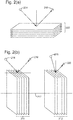
- FIG. 2(a) depicts a VTI anisotropic medium having a plurality of horizontally stratified layers 202, relative to a source 204 and receiver 206 that are used to image the medium.
- VTI media like that shown in Figure 2(a) is typically found where gravity is the dominant factor in the stratification of the layers in the medium to shale, and is otherwise known as media which has polar anisotropy.
- this VTI type of media is that which is analyzed, and whose anisotropy is modeled, in the above U.S. Patent No. 6,901,333 .
- FIG. 2(b) wherein HTI anisotropic mediums 210 and 212 are illustrated.
- the left side of Figure 2(b) illustrates the case with vertically stratified media 210 relative to a source-receiver pair 214, 216 which is oriented in a direction of the principle anisotropy axis 217.
- the right side of Figure 2(b) illustrates another HTI anisotropic medium 212 wherein a source-receiver pair 218, 220 is oriented in a direction perpendicular to the direction of the principle anisotropy axis 217.
- HTI media is typically associated with cracks, fractures and stress and can be found where regional stress is the dominant stratification factor and is otherwise known as media which have azimuthal anisotropy.
- the following embodiments describe techniques for modeling anisotropy parameters associated with media such as that described above with respect to Figure 2(b) .
- AVO Amplitude Versus Offset
- AVO data is converted to other domains, for example to angles for Amplitude Versus Angle (AVA) analysis and interpretation.
- AVA Amplitude Versus Angle
- AVO methods For purposes of the description herein, and in keeping with industry practice, all methods that make use of seismic amplitude changes and in keeping with industry practice, all methods that make use of seismic amplitude changes originating from the measurement of seismic data holding data records with different source-receiver separation are collectively referred to herein as AVO methods.
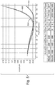
- Figure 3 illustrates, for the example of azimuthal anisotropy, the effect that anisotropy can have on seismic reflection coefficient amplitudes.
- Figure 3 shows the modeled amplitude response of a plane wave incident on a horizontal interface between two layers with and without incorporating HTI anisotropy. The seismic reflection amplitudes are shown as a function of angle (in degrees).
- the solid curve 300 (anis) shows the analytic (exact) reflection coefficient response for a plane wave reflecting from a single, horizontal interface for the case of azimuthal anisotropy and incident and reflected pressure wave.
- the dashed curve 302 (iso) shows the exact solution for the isotropic reflection coefficients.
- the elastic and anisotropy parameters of the layer above and the layer below the interface are specified in the table of Figure 3 , where Vp is the pressure wave velocity in m/s, Vs is the shear wave velocity in m/s, Rho is the density in kg/m3 and eps, del and gam are the Thomsen anisotropy parameters e, ⁇ and ⁇ respectively.
- the properties in the layer above are for an anisotropic shale and those for the layer below are for a water-charged sand that is assumed isotropic.
- the example clearly shows the effect that anisotropy can have on the seismic amplitudes.
- One of the objectives of these embodiments is to define a new class of earth parameters derived from the anisotropy parameters and the elastic parameters, termed anisotropic elastic parameters, for azimuthal anisotropy, such that the effects of azimuthal anisotropy can be modeled to an acceptable level of accuracy when using these parameters in the isotropic modeling of anisotropic seismic data.
- R p ⁇ R 0 + R 2 sin 2 ⁇ + R 4 sin 2 ⁇ tan 2 ⁇ providing the three reflectivity terms for vertical transverse isotropic (VTI) media:
- R 0 1 2 ⁇ Z p Z ⁇ p
- R 0 1 2 ⁇ Z p Z ⁇ p
- the next step is to derive the desired anisotropic elastic parameters, which are denoted by a prime (') accent.
- a close approximation can be obtained by approximating the contrast terms of the anisotropy parameters with new parameters that can be expressed as relative contrasts.
- ⁇ r ⁇ + 1 ⁇ ⁇ ⁇
- the validity of the approximation is verified by calculating the relative contrast of ⁇ r . Taking into account ⁇ ⁇ 1 we see that: ⁇ ⁇ r ⁇ ⁇ r ⁇ ⁇ ⁇ ⁇ The same holds true for ⁇ and ⁇ . When multiple layers are considered, the average can be taken over the set of layers.
- Vs ′ ⁇ r 0.5 / ⁇ r cos 2 ⁇ ⁇ ⁇ ⁇ r / ⁇ r 4 K + 1 / 8 K cos 4 ⁇ ⁇ ⁇ Vs for HTI media.
- This has the advantage that the anisotropic elastic parameters are scaled such that when ⁇ , ⁇ and ⁇ equal 0, they are equal to the input elastic parameters. In comparative data analysis, this nicely emphasizes zones with anisotropy.
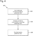
- FIG 4 is a flow chart illustrating the process of one embodiment 400 for deriving azimuthal anisotropic elastic parameters.
- Step 402 represents obtaining the earth elastic parameter data and the azimuthal anisotropy parameter data for an object or imaged area (layer) of interest to use as inputs to the foregoing equations, i.e., data including values for Input V p , V s , ⁇ , ⁇ , ⁇ , y, ⁇ , ⁇ .
- the anisotropy information can be obtained at step 402 by, for example, seismic data processing, where offset and azimuth dependent time shifts are indicative of changes in the propagation velocity. Additionally, at the position of the borehole, one can perform additional seismic experiments to specifically recover HTI and VTI parameters. Such experiments are known as walk-away and walk-around VSP (Vertical Seismic Profiling).
- VSP Vertical Seismic Profiling
- step 404 the transforms are developed, e.g., as shown in Equations 3a', 3b' and 3c', and in step 406 the developed transforms are applied to generate the azimuthal anisotropic elastic parameters, e.g., values for V p ', V s ' and ⁇ ' or I p ', I s ' and ⁇ ' as described above.
- step 406 includes transforming the earth elastic parameter data based on the azimuthal anisotropy parameter data to obtain anisotropic elastic parameter data.
- the output of step 406, i.e., the azimuthal anisotropic elastic parameter data may be applied to at least one of the following methods: isotropic seismic modeling method, an isotropic seismic analysis and interpretation method, an isotropic seismic wavelet estimation method, an isotropic seismic inversion method, or an isotropic method for analysis and interpretation of inversion results.
- the method 400 may also include the step of substituting the azimuthal anisotropic elastic parameter data for isotopic elastic parameters during isotopic seismic modeling method to synthesize anisotropic seismic data. Additionally, the synthesized anisotropic seismic data may be used in an isotropic seismic analysis and interpretation method for analysis and interpretation of anisotropic seismic data. Accordingly, the azimuthal anisotropic elastic parameter data may be substituted for the isotropic elastic parameters in any of the above-mentioned methods.
- Another embodiment is directed to a method for approximating anisotropic seismic modeling by applying isotropic seismic modeling.
- the method includes an initial step of inputting earth elastic parameter data and earth anisotropy parameter data for an area of interest.
- the earth elastic parameter data is transformed to obtain anisotropic elastic parameter data based on the earth anisotropy parameter data.
- Isotropic seismic modeling is then applied on the transformed anisotropic elastic parameter data.
- the resulting modeled anisotropic seismic data is an approximation of seismic data obtained by a corresponding anisotropic seismic modeling.
- the processed anisotropic seismic data is then output.
- the method may further include a step of substituting the anisotropic elastic parameter data for isotropic elastic parameter data to synthesize the anisotropic seismic data.
- the synthesized anisotropic seismic data may be used in an isotropic analysis and interpretation method for analysis and interpretation of the anisotropic seismic data.
- the area of interest may be imaged by acquisition of borehole data, wide azimuth (WAZ) data, three-dimension (3-D) earth models, or four-dimensional (4-D) earth models.
- This step of transforming may further include applying appropriate transform functions that convert the earth elastic parameter data and earth anisotropy parameter data to the anisotropic elastic parameter data.
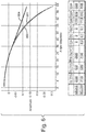
- Figure 5 and Figure 6 illustrate modeling results for two different sets of rock property data, that exhibit relatively strong anisotropy contrasts.
- Figure 5 illustrates the effect, using the same model as for Figure 3 , of using the 3-term approximation for the Zoeppritz equations described above, wherein the curve 500 the anisotropic response and curve 502 shows the isotropic response.
- the dotted curve 504 shows the result of isotropic modeling with the anisotropic elastic parameters specified in the table, where Vpae, Vsae and Rhoae are the anisotropic elastic pressure wave velocity, shear wave velocity and density, respectively, calculated from the transform expressions (3) and using the normalization equation (4).
- FIG. 6 illustrates the same results as in Figure 5 , but for another case.
- the properties in the layer above are for isotropic brine-charged sand and in the layer below are for anisotropic shale.
- curve 600 shows the anisotropic response
- curve 602 shows the isotropic response
- curve 604 shows the response with isotropic modeling with anisotropic elastic parameters.
- the results illustrate that isotropic modeling with the anisotropic elastic parameters closely approximates anisotropic modeling.
- Figure 7 shows panels with borehole log data to demonstrate the effect of transforming elastic parameters to anisotropic elastic parameters for the case of azimuthal anisotropy and incident and reflecting pressure waves.
- Figure 7 illustrates a suite of borehole logs with pressure ( V p ) and shear wave velocity ( V s ) and density (Rho) elastic parameters, the corresponding anisotropic elastic parameters for azimuthal anisotropy and incident and reflecting pressure waves, the shale volume log (Vshale) and logs of ⁇ r and ⁇ r .
- the normalization of equation (4) has been applied to achieve that the anisotropic elastic parameters are equal to the elastic parameters in the pure sand sections (where the shale volume is zero), for example, between Top Unit II and Top Unit I.
- the above derivation is based on the 3-term approximations to the exact isotropic and exact anisotropic modeling solutions for the plane wave, single horizontal interface model. In practice this may not be the desirable model as different situations in regards to the generation of anisotropic elastic parameters can occur, for example, to handle the following: azimuthal anisotropy for p-wave data; different types of anisotropy for shear and converted wave seismic data; use of the exact equations rather than the 3-term approximation; and use of more complex modeling methods.
- constants x, y and z will generally differ for each of the elastic parameters, for each type of anisotropy and for each wave type (pressure, shear and converted wave). It is also noted that the ⁇ , ⁇ and ⁇ averages are part of the formula. When multiple layers are considered, it can be advantageous to also consider these averages as parameters.
- transform functions are obtained that have parameters that control the transform.
- appropriate values for these transform parameters can be obtained analytically.
- an iterative procedure can also be readily followed to obtain the appropriate values for the transform parameters. This results in further important benefits such as: the exact modeling methods rather than the 3-term approximations can be used as reference for the case of the simple single flat interface model, or more complex modeling methods can be applied; and other transform functions with other functional forms and with other transform parameters than equation (5) can be applied to evaluate if a better approximation can be obtained.
- steps 802 and 804 refer to the input of elastic parameter data and anisotropic parameter data, respectively, which can be obtained as previously described with respect to step 402.
- synthetic azimuthal anisotropic seismic amplitude data is generated using an appropriate azimuthal anisotropic forward modeling method selected on such criteria as the type(s) of anisotropy, wave type(s), model complexity and modeling accuracy. Such data is referred to herein as reference azimuthal anisotropic seismic amplitude data.
- transform functions are developed to transform the earth elastic and anisotropy parameters to anisotropic elastic parameters. It can be assumed that the transform functions have certain parameters (the transform parameters) that may be modified.
- a first set of transform functions may be developed by using some set of initial transform parameters.
- Anisotropic elastic parameters are then generated in step 810 by applying the transforms, e.g., the same or similar as those described above with respect to Equations 3a', 3b' and 3c', to the elastic parameter data.
- isotropic forward modeling is applied with the anisotropic elastic parameters using the isotropic equivalent of the anisotropic forward modeling method used in step 808 to generate anisotropic seismic data.
- This equivalence can generally be achieved by setting the anisotropy parameters to 0 (or constant) in the anisotropic forward modeling method.
- the anisotropic seismic data generated by isotropic modeling with the anisotropic elastic parameters is then compared with the reference anisotropic seismic amplitude data in step 814.
- the comparison is judged. If the comparison from step 816 is not satisfactory, then the parameters of the transform functions are updated in step 818, e.g., the direction of the anisotropy axis and the Thomsen parameters, and the transform functions of step 806 are modified accordingly.
- the decision made in block 816 can, for example, be performed based on an analysis of the HTI data with the WAZ seismic (and synthetic) data which is measuring all of the azimuth directions since the HTI has an isotropic plane that should match the well control and an anisotropic plane orthogonal to the isotropic plane which permits the derivation of the anisotropy, azimuth and the elastic properties. Steps 810-818 are repeated until a satisfactory match is obtained. If the comparison at step 816 is satisfactory, then the set of transform functions is produced in step 820.
- the output of the method of this embodiment is a set of transform functions calibrated for the particular anisotropic forward modeling method selected.
- the generated isotropic elastic parameters as well as the anisotropy parameters may also be output, as may the synthesized anisotropic seismic data.
- the forward modeling method referred to in step 608 may be a method for a two-layer (one interface) earth model, or may be a method for multiple layers, or may be a method for a fully inhomogeneous earth. In the last two cases the modeling and comparison may be carried out over a limited interval of interest.
- the modification in step 818 to a fit-for-purpose level of accuracy may be done automatically using an optimization method, or interactively or in combination.
- the equivalent isotropic forward modeling method may also be used.
- the proposed anisotropic elastic parameter transform expressions achieve the objective that the anisotropic elastic parameters are straightforwardly obtained by a point-by-point transform of the elastic parameters.
- An important implication is that, to handle anisotropy, all available isotropic AVO methods for such applications as seismic modeling, wavelet estimation, the inversion and analysis and interpretation of inversion results, and the analysis and interpretation of seismic amplitude data can continue to be applied simply by replacing the isotropic elastic parameters by the above-defined anisotropic elastic parameters at the appropriate points in these methods.
- the transforms will typically be applied to wide azimuth data with the data points in those data sets representing earth elastic and anisotropy parameters at some spatial location or locations in the earth. It is noted that such representations allow for specification of the vertical location in terms of seismic travel time or in distance or depth.
- anisotropic elastic parameters can also be obtained by integration of the contrast expressions such as equation (1). This may result in improved accuracy, as the conversion of the anisotropy parameters to relative contrasts is not needed. However, this gain may be offset by the practical observation that integration can introduce low frequency drift and requires handling of the integration constant. This may not impact further use of the anisotropic elastic parameters, for example, in certain band-limited seismic modeling and inversion methods where these effects are removed in the method. Hence, these are examples where anisotropic elastic parameters obtained by integration can be effectively used. In fact, in certain of these methods band-limited anisotropic elastic parameters can be used.
- An alternative method is to combine anisotropic elastic parameters obtained by an integration procedure with the anisotropic elastic parameters obtained with the point-by-point transforms. This can be achieved by replacing the low frequency part of the result obtained by the integration procedure with the equivalent part obtained with the point-by-point transforms.
- the transform parameters can be a function of depth or lateral position in the earth.
- the above analytic derivation shows that these transform parameters may be a function of K.
- K varies spatially in the earth.
- the transform parameters are assumed constant when a single interface is used for deriving the transforms or are assumed constant over the study interval of interest. When these transforms are applied over longer intervals or areas, this may lead to a loss to of accuracy. This same issue occurs in conventional seismic AVO analysis, as for example discussed in Fatti, J. L., Smith, G. C., Vail, P. J., Strauss, P. J. and Levitt, P.
- Embodiments are also directed to a device for anisotropic processing of earth elastic parameter data and the application of processed data.
- the device includes a first input means for inputting earth elastic parameter data of an area of interest; a second input means for inputting earth anisotropy parameter data of the area of interest; a transform means for transforming, based on the input earth anisotropy parameter data, the input earth elastic parameter data to obtain anisotropic elastic parameter data; a processor for applying the anisotropic elastic parameter data in at least one of the following methods: 1) an isotropic seismic modeling method; 2) an isotropic seismic analysis and interpretation method; 3) an isotropic seismic wavelet estimation method; 4) an isotropic seismic inversion method; and 5) an isotropic method for the analysis and interpretation of inversion results; and an output means for outputting the processed anisotropic elastic parameter data.
- Another embodiment includes a device for approximating anisotropic seismic modeling by applying isotropic seismic modeling.
- the device includes a first input means for inputting earth elastic parameter data of an area of interest; a second input means for inputting earth anisotropy parameter data of the area of interest; a transform means for transforming, based on the input earth anisotropy parameter data, the input earth elastic parameter data to obtain anisotropic elastic parameter data; a processor for applying the isotropic seismic modeling on the transformed anisotropic elastic parameter data, the resulting modeled anisotropic seismic data being an approximation of the data obtained by a corresponding anisotropic seismic modeling; and an output means for outputting the processed anisotropic seismic data.
- anisotropy parameter data anisotropy parameter data.
- An input/output unit 908 may be connected to the CPU 902 and may be of any conventional type, such as a monitor and keyboard, mouse, touchscreen, printer, and/or voice activated device.
- the computer system 900 runs a computer program to execute instructions for the CPU 902 to perform any of the methods of the embodiments described hereinabove.
- the computer system 900 is simply an example of one suitable computer system for the practice of the embodiments. Such computer systems are well understood by one of ordinary skill in the art.
- the computer program may be stored on a data carrier 910, such as a disk electronically connectable with the CPU 902, so as to allow the computer program when run on a computer to execute any of the methods described hereinabove.
- the disclosed embodiments provide a server node, and methods for generation and application of anisotropic elastic parameters in HTI media. It should be understood that this description is not intended to limit the invention. Further, in the detailed description of the embodiments, numerous specific details are set forth in order to provide a comprehensive understanding of the invention. However, one skilled in the art would understand that various embodiments may be practiced without such specific details.
Landscapes
- Engineering & Computer Science (AREA)
- Physics & Mathematics (AREA)
- Remote Sensing (AREA)
- Life Sciences & Earth Sciences (AREA)
- General Physics & Mathematics (AREA)
- Acoustics & Sound (AREA)
- Environmental & Geological Engineering (AREA)
- Geology (AREA)
- General Life Sciences & Earth Sciences (AREA)
- Geophysics (AREA)
- Mathematical Physics (AREA)
- Data Mining & Analysis (AREA)
- Theoretical Computer Science (AREA)
- Computational Mathematics (AREA)
- Mathematical Analysis (AREA)
- Mathematical Optimization (AREA)
- Algebra (AREA)
- Pure & Applied Mathematics (AREA)
- Databases & Information Systems (AREA)
- Software Systems (AREA)
- General Engineering & Computer Science (AREA)
- Geophysics And Detection Of Objects (AREA)
Claims (15)
- Verfahren zur anisotropischen Verarbeitung von erdelastischen Parameterdaten, die mit einem horizontalen transversal-isotropen (HTI)-anisotropischen Medium assoziiert sind, wobei das Medium vertikal geschichtete Schichten mit Bezug auf das Quellen-Empfänger-Paar umfasst und eine Hauptanisotropieachse aufweisen, wobei das Verfahren Folgendes umfasst:Erfassen von seismischen Daten für einen bestimmten Bereich, der eine Schicht eines HTI-anisotropischen Mediums einschließt, umfassend azimuthale anisotropische Eigenschaften, unter Verwendung von mindestens einer Quelle und Empfängern;Erhalten von erdelastischen Parameterdaten (802) die mit dem bestimmten Bereich assoziiert sind;Erhalten von Erdanisotropie-Parameterdaten (804) von dem bestimmten Bereich unter Verwendung des Quellen-Empfänger-Paars bei der seismischen Erfassung und Verwendung eines Azimuths der Hauptanisotropieachse des HTI-Mediums senkrecht zu den Schichten;Entwickeln von Umwandlungsfunktionen (806), die die erdelastischen und Anisotropie-Parameterdaten in anisotropische elastische Parameterdaten umwandeln, basierend auf den erhaltenen Erdanisotropie-Parameterdaten;Anwenden (810) der Umwandlungsfunktionen auf die erdelastischen und Anisotropie-Parameterdaten, um die anisotropischen elastischen Parameterdaten zu erhaltenAnwenden der anisotropischen elastischen Parameterdaten in mindestens einem seismischen Verarbeitungsverfahren, um mindestens die Wahrscheinlichkeit der Abwesenheit oder der Anwesenheit von Kohlenwasserstoff-Lagerstätten zu bestimmen.
- Verfahren nach Anspruch 1, weiter umfassend: Anwenden der anisotropischen elastischen Parameterdaten in mindestens einem seismischen Verarbeitungsverfahren, ausgewählt aus der Gruppe, einschließend: i) ein isotropisches seismisches Modellierungsverfahren, ii) ein isotropisches seismisches Analyse- und Interpretationsverfahren, iii) ein isotropisches seismisches Wavelet-Bestimmungsverfahren, iv) ein isotropisches seismisches Inversionsverfahren und v) ein isotropisches Verfahren zur Analyse und Interpretation von Inversionsergebnissen, um verarbeitete anisotropische elastische Parameterdaten zu erzeugen.
- Verfahren nach Anspruch 2, weiter umfassend Ersetzen der anisotropischen elastischen Parameterdaten durch isotropische elastische Parameterdaten beim isotropischen Verfahren zur Analyse und Interpretation von Inversionsergebnissen.
- Verfahren nach Anspruch 1, wobei der bestimmte Bereich unter Verwendung einer breiten Azimuth-seismischen Erfassungstechnik abgebildet wird, um die elastischen Parameterdaten und die anisotropischen Parameterdaten zu erhalten.
- Verfahren nach Anspruch 1, wobei die Umwandlungsfunktionen

- Verfahren nach Anspruch 1, wobei das Umwandeln von elastischen Parameterdaten in anisotropische elastische Parameterdaten durch Integrieren von anisotropischen elastischen Parameterkontrasten erzielt wird.
- Verfahren nach Anspruch 1, wobei die anisotropischen Parameterdaten in Anisotropie-bezogene Kontrastparameter umgewandelt werden, so dass sich relative Kontraste der umgewandelten Anisotropie-Parameter den Kontrasten in den Anisotropie-Parameterdaten annähern.
- Verfahren nach Anspruch 1, weiter umfassend:
Anwenden von istotropischer seismischer Modellierung auf die umgewandelten anisotropischen elastischen Parameterdaten, um anisotropische seismische Daten zu produzieren, wobei die produzierten anisotropischen seismischen Daten eine Annäherung von seismischen Daten, erhalten durch anisotropische seismisches Modellierung, sind. - Verfahren nach Anspruch 8, weiter umfassend Ersetzen der anisotropischen elastischen Parameterdaten durch isotropische elastische Parameterdaten bei der isotropischen seismischen Modellierung, um anisotropische seismische Daten zu produzieren.
- System zur anisotropischen Verarbeitung von erdelastischen Parameterdaten, die mit einem horizontalen transversal-isotropen (HTI)-anisotropischen Medium assoziiert sind, wobei das Medium vertikal geschichtete Schichten mit Bezug auf das Quellen-Empfänger-Paar aufweist und eine Hauptanisotropieachse umfasst, wobei das System Folgendes umfasst:mindestens einer Quelle und Empfänger, die betrieben werden, um seismische Daten für einen bestimmten Bereich zu erfassen, der eine Schicht eines HTI-anisotropischen Mediums einschließt, aufweisend azimutale anisotropische Eigenschaften;mindestens einen Prozessor (902), der konfiguriert ist, um erdelastische Parameterdaten (802) zu erhalten, die mit dem bestimmten Bereich assoziiert sind; um Erdanisotropie-Parameterdaten (804) von dem bestimmten Bereich unter Verwendung eines Azimuths des Quellen-Empfänger-Paars bei der seismischen Erfassung und unter Verwendung eines Azimuths der Hauptanisotropieachse des HTI-Mediums senkrecht zu den Schichten zu erhalten, wobei der Prozessor weiter konfiguriert ist:um Umwandlungsfunktionen (806, 810) zu entwickeln, die die erdelastischen und Anisotropie-Parameterdaten in anisotropische elastische Parameterdaten umwandeln, basierend auf den erhaltenen Erdanisotropie-Parameterdaten; und die Umwandlungsfunktionen auf die erdelastischen und Anisotropie-Parameterdaten anzuwenden, um die anisotropischen elastischen Parameterdaten zu erhalten;wobei der mindestens eine Prozessor weiter konfiguriert ist, um die anisotropischen elastischen Parameterdaten in mindestens einem seismischen Verarbeitungsverfahren anzuwenden, um mindestens die Wahrscheinlichkeit der Abwesenheit oder der Anwesenheit von Kohlenwasserstoff-Lagerstätten zu bestimmen.
- System nach Anspruch 10, wobei der mindestens eine Prozessor weiter konfiguriert ist, um die anisotropischen elastischen Parameterdaten in mindestens einem seismischen Verarbeitungsverfahren anzuwenden, ausgewählt aus der Gruppe, einschließend: i) ein isotropisches seismisches Modellierungsverfahren, ii) ein isotropisches seismisches Analyse- und Interpretationsverfahren, iii) ein isotropisches seismisches Wavelet-Bestimmungsverfahren, iv) ein isotropisches seismisches Inversionsverfahren und v) ein isotropisches Verfahren zur Analyse und Interpretation von Inversionsergebnissen, um verarbeitete anisotropische elastische Parameterdaten zu erzeugen.
- System nach Anspruch 11, wobei der mindestens eine Prozessor weiter konfiguriert ist, um die anisotropischen elastischen Parameterdaten durch isotropische elastische Parameterdaten beim isotropischen Verfahren zur Analyse und Interpretation von Inversionsergebnissen zu ersetzen.
- System nach Anspruch 10, wobei der bestimmte Bereich unter Verwendung einer breiten Azimuth-seismischen Erfassungstechnik abgebildet wird, um die elastischen Parameterdaten und die anisotropischen Parameterdaten zu erhalten.
- System nach Anspruch 10, wobei die Umwandlungsfunktionen

- System nach Anspruch 10, wobei der mindestens eine Prozessor weiter konfiguriert ist, um die isotropische seismische Modellierung auf die umgewandelten anisotropischen elastischen Parameterdaten anzuwenden, um anisotropische seismische Daten zu produzieren, wobei die produzierten anisotropischen seismischen Daten eine Annäherung von seismischen Daten, erhalten durch anisotropische seismische Modellierung, sind.
Applications Claiming Priority (2)
| Application Number | Priority Date | Filing Date | Title |
|---|---|---|---|
| US201361859361P | 2013-07-29 | 2013-07-29 | |
| PCT/EP2014/066101 WO2015014762A2 (en) | 2013-07-29 | 2014-07-25 | Method and device for the generation and application of anisotropic elastic parameters in horizontal transverse isotropic (hti) media |
Publications (2)
| Publication Number | Publication Date |
|---|---|
| EP3028071A2 EP3028071A2 (de) | 2016-06-08 |
| EP3028071B1 true EP3028071B1 (de) | 2018-07-18 |
Family
ID=51224964
Family Applications (1)
| Application Number | Title | Priority Date | Filing Date |
|---|---|---|---|
| EP14742555.7A Active EP3028071B1 (de) | 2013-07-29 | 2014-07-25 | Verfahren und vorrichtung zur erzeugung und anwendung von anisotropischen elastischen parametern in horizontalen transversal-isotropen (hti-)medien |
Country Status (5)
| Country | Link |
|---|---|
| US (1) | US20150293245A1 (de) |
| EP (1) | EP3028071B1 (de) |
| CA (1) | CA2920008C (de) |
| MX (1) | MX2016001417A (de) |
| WO (1) | WO2015014762A2 (de) |
Families Citing this family (26)
| Publication number | Priority date | Publication date | Assignee | Title |
|---|---|---|---|---|
| EP2856373A4 (de) * | 2012-05-24 | 2016-06-29 | Exxonmobil Upstream Res Co | System und verfahren zur vorhersage der gesteinsfestigkeit |
| GB2521268A (en) * | 2013-11-27 | 2015-06-17 | Chevron Usa Inc | Determining reserves of a reservoir |
| CN105068117B (zh) * | 2015-08-25 | 2016-06-08 | 中国矿业大学(北京) | 用于裂缝性介质的avo反演方法、装置和设备 |
| AU2016386431A1 (en) * | 2016-01-15 | 2018-06-28 | Landmark Graphics Corporation | Semblance-based anisotropy parameter estimation using isotropic depth-migrated common image gathers |
| US10520621B2 (en) | 2016-11-23 | 2019-12-31 | Cgg Services Sas | Method and apparatus for simultaneous geostatistical inversion of time-lapse seismic data |
| CN106772578B (zh) * | 2016-12-07 | 2018-11-09 | 中国矿业大学(北京) | 一种合成地震记录的方法和装置 |
| CN106646597B (zh) * | 2016-12-14 | 2018-11-27 | 中国石油天然气集团有限公司 | 基于弹簧网络模型的正演模拟方法及装置 |
| US11243318B2 (en) * | 2017-01-13 | 2022-02-08 | Cgg Services Sas | Method and apparatus for unambiguously estimating seismic anisotropy parameters |
| CN106908839B (zh) * | 2017-05-05 | 2018-09-28 | 中国石油大学(华东) | 一种地震波精确反射系数解析方法及装置 |
| CN109270575B (zh) * | 2018-11-02 | 2019-11-26 | 河南理工大学 | 一种基于建筑物地震响应等效的爆破地震波模型构造方法 |
| US11828895B2 (en) * | 2019-08-05 | 2023-11-28 | Geosoftware C.V. | Methods and devices using effective elastic parameter values for anisotropic media |
| CN112558153B (zh) * | 2019-09-25 | 2022-03-29 | 中国石油天然气股份有限公司 | 一种双相介质的油气储层预测方法及装置 |
| CN111460602B (zh) * | 2019-12-06 | 2021-01-29 | 西南石油大学 | 基于岩石物理建模的横观各向同性地层地应力预测方法 |
| CN111551990B (zh) * | 2020-04-07 | 2023-05-23 | 西安科技大学 | 一种hti型煤层地震波反射系数的获取系统 |
| CN114185092B (zh) * | 2020-09-15 | 2024-05-07 | 中国石油化工股份有限公司 | 储层水平缝发育程度评价方法、装置、电子设备及介质 |
| CN113009572B (zh) * | 2021-02-23 | 2022-07-01 | 成都理工大学 | 一种基于横波偏振分析预测裂缝方位角的方法 |
| CN115113273A (zh) * | 2021-03-22 | 2022-09-27 | 中国石油化工股份有限公司 | 裂缝参数的确定方法、装置、设备及存储介质 |
| CN113341455B (zh) * | 2021-06-24 | 2024-02-09 | 中国石油大学(北京) | 一种粘滞各向异性介质地震波数值模拟方法、装置及设备 |
| CN113933898B (zh) * | 2021-09-23 | 2022-07-19 | 中国地质大学(武汉) | 裂缝储层各向异性特征识别方法、装置、设备及存储介质 |
| CN115097520A (zh) * | 2022-06-09 | 2022-09-23 | 中国人民解放军国防科技大学 | 一种多量vsp数据的频率相关各向异性横波分裂算法 |
| CN115857004B (zh) * | 2022-11-29 | 2024-07-02 | 河海大学 | 页岩储层vti介质的高分辨率多波联合叠前反演方法 |
| WO2024191797A1 (en) * | 2023-03-10 | 2024-09-19 | Schlumberger Technology Corporation | Methods and computing systems for implementing amplitude inversion |
| CN119716994B (zh) * | 2023-09-26 | 2025-09-12 | 中国石油天然气集团有限公司 | 分方位各向异性初至射线追踪方法、装置、设备及介质 |
| CN119846693B (zh) * | 2023-10-16 | 2025-11-07 | 中国石油化工股份有限公司 | 一种hti介质脆性地震预测稳定方法 |
| CN119199988B (zh) * | 2024-11-22 | 2025-02-11 | 中国海洋大学 | 一种基于两步法的vti介质各向异性参数反演方法 |
| CN119511370B (zh) * | 2024-12-04 | 2025-08-29 | 长安大学 | 一种横向各向同性介质地震波群速度分布的计算方法 |
Family Cites Families (4)
| Publication number | Priority date | Publication date | Assignee | Title |
|---|---|---|---|---|
| US6901333B2 (en) * | 2003-10-27 | 2005-05-31 | Fugro N.V. | Method and device for the generation and application of anisotropic elastic parameters |
| US8120991B2 (en) * | 2006-11-03 | 2012-02-21 | Paradigm Geophysical (Luxembourg) S.A.R.L. | System and method for full azimuth angle domain imaging in reduced dimensional coordinate systems |
| EP2248007A1 (de) * | 2008-02-28 | 2010-11-10 | Exxonmobil Upstream Research Company | Gesteinsphysikmodell zur simulation der seismischen reaktion in gebrochenem schichtgestein |
| WO2011112932A1 (en) * | 2010-03-12 | 2011-09-15 | Cggveritas Services (Us) Inc. | Methods and systems for performing azimuthal simultaneous elatic inversion |
-
2014
- 2014-07-25 US US14/432,543 patent/US20150293245A1/en not_active Abandoned
- 2014-07-25 WO PCT/EP2014/066101 patent/WO2015014762A2/en not_active Ceased
- 2014-07-25 MX MX2016001417A patent/MX2016001417A/es active IP Right Grant
- 2014-07-25 EP EP14742555.7A patent/EP3028071B1/de active Active
- 2014-07-25 CA CA2920008A patent/CA2920008C/en active Active
Non-Patent Citations (1)
| Title |
|---|
| RÜGER A: "Variation of P-wave reflectivity with offset and azimuth in anisotropic media", GEOPHYSICS, SOCIETY OF EXPLORATION GEOPHYSICISTS, US, vol. 63, no. 3, 1 May 1998 (1998-05-01), pages 935 - 947, XP002326797, ISSN: 0016-8033, DOI: 10.1190/1.1444405 * |
Also Published As
| Publication number | Publication date |
|---|---|
| EP3028071A2 (de) | 2016-06-08 |
| WO2015014762A2 (en) | 2015-02-05 |
| US20150293245A1 (en) | 2015-10-15 |
| CA2920008C (en) | 2017-06-13 |
| MX2016001417A (es) | 2016-08-18 |
| WO2015014762A3 (en) | 2015-04-02 |
| CA2920008A1 (en) | 2015-02-05 |
Similar Documents
| Publication | Publication Date | Title |
|---|---|---|
| EP3028071B1 (de) | Verfahren und vorrichtung zur erzeugung und anwendung von anisotropischen elastischen parametern in horizontalen transversal-isotropen (hti-)medien | |
| US6901333B2 (en) | Method and device for the generation and application of anisotropic elastic parameters | |
| US11828895B2 (en) | Methods and devices using effective elastic parameter values for anisotropic media | |
| US8352190B2 (en) | Method for analyzing multiple geophysical data sets | |
| Warner et al. | Anisotropic 3D full-waveform inversion | |
| US11493658B2 (en) | Computer-implemented method and system employing nonlinear direct prestack seismic inversion for poisson impedance | |
| AU2011224165B2 (en) | Methods and systems for performing azimuthal simultaneous elastic inversion | |
| EP3076205B1 (de) | Verfahren zur vermessungsdatenverarbeitung zur kompensation visko-akustischer effekte in reverse-time-migration mit geneigter transversaler isotropie | |
| AU2014273165B2 (en) | High resolution estimation of attenuation from vertical seismic profiles | |
| EP4042210B1 (de) | Bestimmung von eigenschaften einer unterirdischen formation unter verwendung einer schallwellengleichung mit einer reflektivitätsparametrisierung | |
| US7082368B2 (en) | Seismic event correlation and Vp-Vs estimation | |
| EP3358376B1 (de) | Verfahren und vorrichtung zur eindeutigen schätzung seismischer anisotropieparameter | |
| US7315783B2 (en) | Traveltime calculation in three dimensional transversely isotropic (3D TI) media by the fast marching method | |
| EP2160633B1 (de) | Erzeugung eines absorptionsparametermodells | |
| CN103635831A (zh) | 在3d各向异性介质中的基于敏感度内核的偏移速度分析 | |
| US20120095690A1 (en) | Methods and computer-readable medium to implement inversion of angle gathers for rock physics reflectivity attributes | |
| CN108139498A (zh) | 具有振幅保持的fwi模型域角度叠加 | |
| US20220373703A1 (en) | Methods and systems for generating an image of a subterranean formation based on low frequency reconstructed seismic data | |
| Tang et al. | Borehole acoustic full-waveform inversion | |
| Vigh et al. | Elastic full-waveform inversion using OBN data acquisition | |
| Li et al. | Wave-equation migration velocity analysis for VTI models | |
| US8411529B2 (en) | Walkaway VSP calibrated sonic logs | |
| Landrø et al. | Seismic critical-angle reflectometry: A method to characterize azimuthal anisotropy? | |
| Gibson Jr et al. | Modeling and velocity analysis with a wavefront-construction algorithm for anisotropic media | |
| Jaimes-Osorio et al. | Amplitude variation with offset inversion using acoustic-elastic local solver |
Legal Events
| Date | Code | Title | Description |
|---|---|---|---|
| PUAI | Public reference made under article 153(3) epc to a published international application that has entered the european phase |
Free format text: ORIGINAL CODE: 0009012 |
|
| 17P | Request for examination filed |
Effective date: 20160128 |
|
| AK | Designated contracting states |
Kind code of ref document: A2 Designated state(s): AL AT BE BG CH CY CZ DE DK EE ES FI FR GB GR HR HU IE IS IT LI LT LU LV MC MK MT NL NO PL PT RO RS SE SI SK SM TR |
|
| AX | Request for extension of the european patent |
Extension state: BA ME |
|
| 17Q | First examination report despatched |
Effective date: 20160727 |
|
| DAX | Request for extension of the european patent (deleted) | ||
| GRAP | Despatch of communication of intention to grant a patent |
Free format text: ORIGINAL CODE: EPIDOSNIGR1 |
|
| INTG | Intention to grant announced |
Effective date: 20180226 |
|
| RAP1 | Party data changed (applicant data changed or rights of an application transferred) |
Owner name: CGG SERVICES SAS |
|
| GRAS | Grant fee paid |
Free format text: ORIGINAL CODE: EPIDOSNIGR3 |
|
| GRAA | (expected) grant |
Free format text: ORIGINAL CODE: 0009210 |
|
| AK | Designated contracting states |
Kind code of ref document: B1 Designated state(s): AL AT BE BG CH CY CZ DE DK EE ES FI FR GB GR HR HU IE IS IT LI LT LU LV MC MK MT NL NO PL PT RO RS SE SI SK SM TR |
|
| REG | Reference to a national code |
Ref country code: GB Ref legal event code: FG4D |
|
| REG | Reference to a national code |
Ref country code: FR Ref legal event code: PLFP Year of fee payment: 5 |
|
| REG | Reference to a national code |
Ref country code: CH Ref legal event code: EP |
|
| REG | Reference to a national code |
Ref country code: IE Ref legal event code: FG4D |
|
| REG | Reference to a national code |
Ref country code: AT Ref legal event code: REF Ref document number: 1019966 Country of ref document: AT Kind code of ref document: T Effective date: 20180815 |
|
| REG | Reference to a national code |
Ref country code: DE Ref legal event code: R096 Ref document number: 602014028713 Country of ref document: DE |
|
| REG | Reference to a national code |
Ref country code: NL Ref legal event code: FP |
|
| REG | Reference to a national code |
Ref country code: NO Ref legal event code: T2 Effective date: 20180718 |
|
| REG | Reference to a national code |
Ref country code: LT Ref legal event code: MG4D |
|
| REG | Reference to a national code |
Ref country code: AT Ref legal event code: MK05 Ref document number: 1019966 Country of ref document: AT Kind code of ref document: T Effective date: 20180718 |
|
| PG25 | Lapsed in a contracting state [announced via postgrant information from national office to epo] |
Ref country code: PL Free format text: LAPSE BECAUSE OF FAILURE TO SUBMIT A TRANSLATION OF THE DESCRIPTION OR TO PAY THE FEE WITHIN THE PRESCRIBED TIME-LIMIT Effective date: 20180718 Ref country code: LT Free format text: LAPSE BECAUSE OF FAILURE TO SUBMIT A TRANSLATION OF THE DESCRIPTION OR TO PAY THE FEE WITHIN THE PRESCRIBED TIME-LIMIT Effective date: 20180718 Ref country code: RS Free format text: LAPSE BECAUSE OF FAILURE TO SUBMIT A TRANSLATION OF THE DESCRIPTION OR TO PAY THE FEE WITHIN THE PRESCRIBED TIME-LIMIT Effective date: 20180718 Ref country code: SE Free format text: LAPSE BECAUSE OF FAILURE TO SUBMIT A TRANSLATION OF THE DESCRIPTION OR TO PAY THE FEE WITHIN THE PRESCRIBED TIME-LIMIT Effective date: 20180718 Ref country code: GR Free format text: LAPSE BECAUSE OF FAILURE TO SUBMIT A TRANSLATION OF THE DESCRIPTION OR TO PAY THE FEE WITHIN THE PRESCRIBED TIME-LIMIT Effective date: 20181019 Ref country code: BG Free format text: LAPSE BECAUSE OF FAILURE TO SUBMIT A TRANSLATION OF THE DESCRIPTION OR TO PAY THE FEE WITHIN THE PRESCRIBED TIME-LIMIT Effective date: 20181018 Ref country code: AT Free format text: LAPSE BECAUSE OF FAILURE TO SUBMIT A TRANSLATION OF THE DESCRIPTION OR TO PAY THE FEE WITHIN THE PRESCRIBED TIME-LIMIT Effective date: 20180718 Ref country code: IS Free format text: LAPSE BECAUSE OF FAILURE TO SUBMIT A TRANSLATION OF THE DESCRIPTION OR TO PAY THE FEE WITHIN THE PRESCRIBED TIME-LIMIT Effective date: 20181118 Ref country code: FI Free format text: LAPSE BECAUSE OF FAILURE TO SUBMIT A TRANSLATION OF THE DESCRIPTION OR TO PAY THE FEE WITHIN THE PRESCRIBED TIME-LIMIT Effective date: 20180718 |
|
| REG | Reference to a national code |
Ref country code: DE Ref legal event code: R119 Ref document number: 602014028713 Country of ref document: DE |
|
| PG25 | Lapsed in a contracting state [announced via postgrant information from national office to epo] |
Ref country code: HR Free format text: LAPSE BECAUSE OF FAILURE TO SUBMIT A TRANSLATION OF THE DESCRIPTION OR TO PAY THE FEE WITHIN THE PRESCRIBED TIME-LIMIT Effective date: 20180718 Ref country code: LV Free format text: LAPSE BECAUSE OF FAILURE TO SUBMIT A TRANSLATION OF THE DESCRIPTION OR TO PAY THE FEE WITHIN THE PRESCRIBED TIME-LIMIT Effective date: 20180718 Ref country code: AL Free format text: LAPSE BECAUSE OF FAILURE TO SUBMIT A TRANSLATION OF THE DESCRIPTION OR TO PAY THE FEE WITHIN THE PRESCRIBED TIME-LIMIT Effective date: 20180718 |
|
| REG | Reference to a national code |
Ref country code: CH Ref legal event code: PL |
|
| PG25 | Lapsed in a contracting state [announced via postgrant information from national office to epo] |
Ref country code: LU Free format text: LAPSE BECAUSE OF NON-PAYMENT OF DUE FEES Effective date: 20180725 |
|
| REG | Reference to a national code |
Ref country code: BE Ref legal event code: MM Effective date: 20180731 |
|
| REG | Reference to a national code |
Ref country code: IE Ref legal event code: MM4A |
|
| PG25 | Lapsed in a contracting state [announced via postgrant information from national office to epo] |
Ref country code: EE Free format text: LAPSE BECAUSE OF FAILURE TO SUBMIT A TRANSLATION OF THE DESCRIPTION OR TO PAY THE FEE WITHIN THE PRESCRIBED TIME-LIMIT Effective date: 20180718 Ref country code: IT Free format text: LAPSE BECAUSE OF FAILURE TO SUBMIT A TRANSLATION OF THE DESCRIPTION OR TO PAY THE FEE WITHIN THE PRESCRIBED TIME-LIMIT Effective date: 20180718 Ref country code: RO Free format text: LAPSE BECAUSE OF FAILURE TO SUBMIT A TRANSLATION OF THE DESCRIPTION OR TO PAY THE FEE WITHIN THE PRESCRIBED TIME-LIMIT Effective date: 20180718 Ref country code: CH Free format text: LAPSE BECAUSE OF NON-PAYMENT OF DUE FEES Effective date: 20180731 Ref country code: CZ Free format text: LAPSE BECAUSE OF FAILURE TO SUBMIT A TRANSLATION OF THE DESCRIPTION OR TO PAY THE FEE WITHIN THE PRESCRIBED TIME-LIMIT Effective date: 20180718 Ref country code: DE Free format text: LAPSE BECAUSE OF NON-PAYMENT OF DUE FEES Effective date: 20190201 Ref country code: ES Free format text: LAPSE BECAUSE OF FAILURE TO SUBMIT A TRANSLATION OF THE DESCRIPTION OR TO PAY THE FEE WITHIN THE PRESCRIBED TIME-LIMIT Effective date: 20180718 Ref country code: IE Free format text: LAPSE BECAUSE OF NON-PAYMENT OF DUE FEES Effective date: 20180725 Ref country code: LI Free format text: LAPSE BECAUSE OF NON-PAYMENT OF DUE FEES Effective date: 20180731 Ref country code: MC Free format text: LAPSE BECAUSE OF FAILURE TO SUBMIT A TRANSLATION OF THE DESCRIPTION OR TO PAY THE FEE WITHIN THE PRESCRIBED TIME-LIMIT Effective date: 20180718 |
|
| PLBE | No opposition filed within time limit |
Free format text: ORIGINAL CODE: 0009261 |
|
| STAA | Information on the status of an ep patent application or granted ep patent |
Free format text: STATUS: NO OPPOSITION FILED WITHIN TIME LIMIT |
|
| PG25 | Lapsed in a contracting state [announced via postgrant information from national office to epo] |
Ref country code: SK Free format text: LAPSE BECAUSE OF FAILURE TO SUBMIT A TRANSLATION OF THE DESCRIPTION OR TO PAY THE FEE WITHIN THE PRESCRIBED TIME-LIMIT Effective date: 20180718 Ref country code: SM Free format text: LAPSE BECAUSE OF FAILURE TO SUBMIT A TRANSLATION OF THE DESCRIPTION OR TO PAY THE FEE WITHIN THE PRESCRIBED TIME-LIMIT Effective date: 20180718 Ref country code: BE Free format text: LAPSE BECAUSE OF NON-PAYMENT OF DUE FEES Effective date: 20180731 Ref country code: DK Free format text: LAPSE BECAUSE OF FAILURE TO SUBMIT A TRANSLATION OF THE DESCRIPTION OR TO PAY THE FEE WITHIN THE PRESCRIBED TIME-LIMIT Effective date: 20180718 |
|
| 26N | No opposition filed |
Effective date: 20190423 |
|
| PG25 | Lapsed in a contracting state [announced via postgrant information from national office to epo] |
Ref country code: SI Free format text: LAPSE BECAUSE OF FAILURE TO SUBMIT A TRANSLATION OF THE DESCRIPTION OR TO PAY THE FEE WITHIN THE PRESCRIBED TIME-LIMIT Effective date: 20180718 |
|
| PG25 | Lapsed in a contracting state [announced via postgrant information from national office to epo] |
Ref country code: MT Free format text: LAPSE BECAUSE OF NON-PAYMENT OF DUE FEES Effective date: 20180725 |
|
| PG25 | Lapsed in a contracting state [announced via postgrant information from national office to epo] |
Ref country code: TR Free format text: LAPSE BECAUSE OF FAILURE TO SUBMIT A TRANSLATION OF THE DESCRIPTION OR TO PAY THE FEE WITHIN THE PRESCRIBED TIME-LIMIT Effective date: 20180718 |
|
| PG25 | Lapsed in a contracting state [announced via postgrant information from national office to epo] |
Ref country code: PT Free format text: LAPSE BECAUSE OF FAILURE TO SUBMIT A TRANSLATION OF THE DESCRIPTION OR TO PAY THE FEE WITHIN THE PRESCRIBED TIME-LIMIT Effective date: 20180718 |
|
| PG25 | Lapsed in a contracting state [announced via postgrant information from national office to epo] |
Ref country code: HU Free format text: LAPSE BECAUSE OF FAILURE TO SUBMIT A TRANSLATION OF THE DESCRIPTION OR TO PAY THE FEE WITHIN THE PRESCRIBED TIME-LIMIT; INVALID AB INITIO Effective date: 20140725 Ref country code: MK Free format text: LAPSE BECAUSE OF NON-PAYMENT OF DUE FEES Effective date: 20180718 Ref country code: CY Free format text: LAPSE BECAUSE OF FAILURE TO SUBMIT A TRANSLATION OF THE DESCRIPTION OR TO PAY THE FEE WITHIN THE PRESCRIBED TIME-LIMIT Effective date: 20180718 |
|
| REG | Reference to a national code |
Ref country code: GB Ref legal event code: 732E Free format text: REGISTERED BETWEEN 20230105 AND 20230111 |
|
| PGFP | Annual fee paid to national office [announced via postgrant information from national office to epo] |
Ref country code: NL Payment date: 20250721 Year of fee payment: 12 |
|
| PGFP | Annual fee paid to national office [announced via postgrant information from national office to epo] |
Ref country code: NO Payment date: 20250725 Year of fee payment: 12 |
|
| PGFP | Annual fee paid to national office [announced via postgrant information from national office to epo] |
Ref country code: GB Payment date: 20250722 Year of fee payment: 12 |
|
| PGFP | Annual fee paid to national office [announced via postgrant information from national office to epo] |
Ref country code: FR Payment date: 20250725 Year of fee payment: 12 |