EP3026992A1 - Blindage magnétique amélioré - Google Patents
Blindage magnétique amélioré Download PDFInfo
- Publication number
- EP3026992A1 EP3026992A1 EP15195646.3A EP15195646A EP3026992A1 EP 3026992 A1 EP3026992 A1 EP 3026992A1 EP 15195646 A EP15195646 A EP 15195646A EP 3026992 A1 EP3026992 A1 EP 3026992A1
- Authority
- EP
- European Patent Office
- Prior art keywords
- layers
- magnetic shielding
- polymer
- magnetic
- layer
- Prior art date
- Legal status (The legal status is an assumption and is not a legal conclusion. Google has not performed a legal analysis and makes no representation as to the accuracy of the status listed.)
- Withdrawn
Links
- 230000005291 magnetic effect Effects 0.000 title claims abstract description 49
- 239000002184 metal Substances 0.000 claims abstract description 37
- 229910052751 metal Inorganic materials 0.000 claims abstract description 37
- 230000005294 ferromagnetic effect Effects 0.000 claims abstract description 33
- 239000000463 material Substances 0.000 claims abstract description 24
- 239000000843 powder Substances 0.000 claims abstract description 24
- 239000007769 metal material Substances 0.000 claims abstract description 3
- XEEYBQQBJWHFJM-UHFFFAOYSA-N Iron Chemical compound [Fe] XEEYBQQBJWHFJM-UHFFFAOYSA-N 0.000 claims description 26
- 229920000642 polymer Polymers 0.000 claims description 23
- 229910052742 iron Inorganic materials 0.000 claims description 12
- PXHVJJICTQNCMI-UHFFFAOYSA-N Nickel Chemical compound [Ni] PXHVJJICTQNCMI-UHFFFAOYSA-N 0.000 claims description 11
- 239000002861 polymer material Substances 0.000 claims description 11
- 229920001684 low density polyethylene Polymers 0.000 claims description 6
- 239000004702 low-density polyethylene Substances 0.000 claims description 6
- 229910000889 permalloy Inorganic materials 0.000 claims description 6
- 229910000859 α-Fe Inorganic materials 0.000 claims description 6
- 229910000531 Co alloy Inorganic materials 0.000 claims description 3
- 229910000990 Ni alloy Inorganic materials 0.000 claims description 3
- 229920001971 elastomer Polymers 0.000 claims description 3
- 239000000806 elastomer Substances 0.000 claims description 3
- 239000003822 epoxy resin Substances 0.000 claims description 3
- 229920000647 polyepoxide Polymers 0.000 claims description 3
- 230000035699 permeability Effects 0.000 description 10
- 239000006260 foam Substances 0.000 description 6
- 239000000203 mixture Substances 0.000 description 5
- 230000035939 shock Effects 0.000 description 5
- 238000010438 heat treatment Methods 0.000 description 3
- 239000005300 metallic glass Substances 0.000 description 3
- 229910052759 nickel Inorganic materials 0.000 description 3
- 238000013155 cardiography Methods 0.000 description 2
- 229910017052 cobalt Inorganic materials 0.000 description 2
- 239000010941 cobalt Substances 0.000 description 2
- GUTLYIVDDKVIGB-UHFFFAOYSA-N cobalt atom Chemical compound [Co] GUTLYIVDDKVIGB-UHFFFAOYSA-N 0.000 description 2
- 230000000694 effects Effects 0.000 description 2
- 238000005259 measurement Methods 0.000 description 2
- 229910000697 metglas Inorganic materials 0.000 description 2
- 229910000640 Fe alloy Inorganic materials 0.000 description 1
- 229910001182 Mo alloy Inorganic materials 0.000 description 1
- 229910003962 NiZn Inorganic materials 0.000 description 1
- UCKMPCXJQFINFW-UHFFFAOYSA-N Sulphide Chemical compound [S-2] UCKMPCXJQFINFW-UHFFFAOYSA-N 0.000 description 1
- 229910045601 alloy Inorganic materials 0.000 description 1
- 239000000956 alloy Substances 0.000 description 1
- 239000002131 composite material Substances 0.000 description 1
- 229920001940 conductive polymer Polymers 0.000 description 1
- 229910052802 copper Inorganic materials 0.000 description 1
- 239000010949 copper Substances 0.000 description 1
- 230000005489 elastic deformation Effects 0.000 description 1
- 239000003302 ferromagnetic material Substances 0.000 description 1
- 239000000945 filler Substances 0.000 description 1
- 239000012535 impurity Substances 0.000 description 1
- 238000009413 insulation Methods 0.000 description 1
- 238000003754 machining Methods 0.000 description 1
- 230000005381 magnetic domain Effects 0.000 description 1
- 238000004519 manufacturing process Methods 0.000 description 1
- 230000002107 myocardial effect Effects 0.000 description 1
- 150000004767 nitrides Chemical class 0.000 description 1
- 230000000135 prohibitive effect Effects 0.000 description 1
- 125000006850 spacer group Chemical group 0.000 description 1
Images
Classifications
-
- H—ELECTRICITY
- H05—ELECTRIC TECHNIQUES NOT OTHERWISE PROVIDED FOR
- H05K—PRINTED CIRCUITS; CASINGS OR CONSTRUCTIONAL DETAILS OF ELECTRIC APPARATUS; MANUFACTURE OF ASSEMBLAGES OF ELECTRICAL COMPONENTS
- H05K9/00—Screening of apparatus or components against electric or magnetic fields
- H05K9/0073—Shielding materials
- H05K9/0081—Electromagnetic shielding materials, e.g. EMI, RFI shielding
-
- H—ELECTRICITY
- H01—ELECTRIC ELEMENTS
- H01F—MAGNETS; INDUCTANCES; TRANSFORMERS; SELECTION OF MATERIALS FOR THEIR MAGNETIC PROPERTIES
- H01F27/00—Details of transformers or inductances, in general
- H01F27/34—Special means for preventing or reducing unwanted electric or magnetic effects, e.g. no-load losses, reactive currents, harmonics, oscillations, leakage fields
- H01F27/36—Electric or magnetic shields or screens
- H01F27/366—Electric or magnetic shields or screens made of ferromagnetic material
-
- H—ELECTRICITY
- H01—ELECTRIC ELEMENTS
- H01F—MAGNETS; INDUCTANCES; TRANSFORMERS; SELECTION OF MATERIALS FOR THEIR MAGNETIC PROPERTIES
- H01F27/00—Details of transformers or inductances, in general
- H01F27/34—Special means for preventing or reducing unwanted electric or magnetic effects, e.g. no-load losses, reactive currents, harmonics, oscillations, leakage fields
- H01F27/36—Electric or magnetic shields or screens
-
- H—ELECTRICITY
- H05—ELECTRIC TECHNIQUES NOT OTHERWISE PROVIDED FOR
- H05K—PRINTED CIRCUITS; CASINGS OR CONSTRUCTIONAL DETAILS OF ELECTRIC APPARATUS; MANUFACTURE OF ASSEMBLAGES OF ELECTRICAL COMPONENTS
- H05K9/00—Screening of apparatus or components against electric or magnetic fields
- H05K9/0073—Shielding materials
- H05K9/0075—Magnetic shielding materials
Definitions
- the invention relates to a magnetic shielding device whose impact resistance is improved.
- a magnetic shield is a conductive envelope that separates the space into two spaces to be magnetically isolated from each other.
- the purpose of a magnetic shielding is twofold, it serves both to contain the magnetic fields inside the shielded enclosure, and to prevent the introduction into the enclosure of external magnetic fields.
- Magnetic shields are made using ferromagnetic materials with high magnetic susceptibility and a low coercive field. They have a high relative magnetic permeability and may for example be soft iron or permalloy. By high relative magnetic permeability, ⁇ r > 1000 is understood.
- the quality of a magnetic shielding is essential in the field of magneto-cardiography, that is to say, the study of the electrical activity of the myocardial cells. To achieve correct and reliable measurements, it is essential that the person who is subject to the medical examination be isolated from any external magnetic field that may interfere with the measurements made. Under the effect of a mechanical or thermal shock, the magnetic domains of the material used to carry out the shielding may be degraded, and this results in a decrease in the effectiveness of the magnetic shielding.
- An object of the invention is to provide a magnetic shield whose performance is improved and maintained over time.
- the invention relates to a magnetic shield comprising at least one side wall defining a cavity for containing an object to be magnetically insulated.
- the side wall comprises at least one layer of ferromagnetic metallic material and at least one layer of polymeric material comprising a ferromagnetic powder.
- At least one of the metal layers and at least one of the polymer layers have a common interface.
- the magnetic shielding may comprise between three and five metal layers, and between three and five polymer layers comprising a ferromagnetic powder, two adjacent metal layers being separated by a layer of polymeric material.
- the magnetic shielding may comprise an outer polymer layer comprising a ferromagnetic powder.
- the materials of the ferromagnetic metal layers and the ferromagnetic powder may be selected from soft iron, permalloy, iron and / or nickel and / or cobalt alloys, and ferrites.
- the polymeric material may be selected from epoxy resin, elastomers or low density polyethylene.
- the thickness of at least one layer of polymer material may be between 1 mm and 10 cm.
- an object can be placed in a cavity whose walls form a magnetic shield.
- the walls of the cavity can be made using a ferromagnetic metal layer machined to achieve the desired shape (cylindrical, spherical, parallelepiped, etc.).
- Machining weakens the structure of the ferromagnetic metal layer at the atomic scale, which limits its effectiveness as a magnetic shield.
- the metal layer is then subjected to one or more heat treatments aimed at improving the crystalline structure of the material and to remove impurities present in the material (carbide, sulfide, nitrides) that could limit the quality of the shielding.
- the ferromagnetic metal layer is generally subjected to a temperature of between 1000 and 1200 ° C. for a duration of between 1 and 6 hours. Then, the temperature is reduced in a controlled manner to avoid embrittlement of the material.
- the mechanical and thermal strength of the metal layer is less, and mechanical or thermal shocks can alter the quality of the shielding. It is therefore essential to handle the metal layer with care and not to subject it to sudden changes in temperature so as not to alter its effectiveness over time.
- the cavity can be made by combining several ferromagnetic metal layers separated by spacers or by foam plates. These elements, however, exert mechanical stresses on the metal layers, and alter the quality of the shielding.
- the thickness of the metal layers is generally between 1 and 3 mm, and the thickness of the foam layers is of the order of 1 to 5 cm.
- Such a device can be cumbersome.
- the invention therefore consists in producing a cavity 1 having walls resistant to thermal and mechanical shocks, and whose size is limited compared to a device comprising metal layers and foam layers.
- the cavity 1 comprises at least one ferromagnetic metal layer 2 surrounded by at least one layer of polymer material 3 comprising a ferromagnetic powder.
- the ferromagnetic metal layers 2 and the polymer layers 3 comprising a ferromagnetic powder can be made in different forms depending on the quality of the desired magnetic shielding.
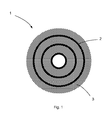
- the layers may for example be cylindrical as in the embodiment of the figure 1 , schematically illustrating a sectional view of a cavity 1 of cylindrical shape.
- the cavity 1 may also be parallelepipedal or spherical, or have any shape if it is preferable for the magnetic shielding to be more efficient.
- At least one of the metal layers 2 may be in contact with at least one of the layers of polymeric material 3, so as to limit the interstices between the various elements making up the device, and therefore to increase its compactness.
- the metal layers 2 and the layers of polymer material 3 can therefore have a common interface.
- each polymer layer 3 serves as a thermal and mechanical damper vis-à-vis the metal layers 2 which are located on either side of the polymer layer 3 considered.
- the walls of the cavity 1 can contain between three and five ferromagnetic metal layers 2 and between three and five polymer layers 3 each comprising a ferromagnetic powder, two adjacent metal layers 2 which can separated by a layer of polymer material 3.
- the inventors have indeed found that the effectiveness of the shielding is significantly improved when the device 1 comprises alternately three metal layers 2 and three polymer layers 3 comprising a ferromagnetic powder, with respect to a device 1 comprising alternately two metal layers 2 and two polymer layers 3 comprising a ferromagnetic powder.
- the metal layers 2 may be made of identical or different materials.
- the material may be identical for all the metal layers 2.
- the metal layers 2 may for example be made of soft iron, permalloy, ferrite or alloy based on iron and / or nickel and / or cobalt.
- the layers of polymer material 3 have a thickness advantageously between 1 mm and 10 cm.
- the layers of polymer material 3 may have a thickness of 1 to 10 cm. They can for example be made from epoxy resin, elastomer or low density polyethylene.
- the polymer layers 3 can be made of different materials, even if, for reasons of simplicity of manufacture, the polymer layers 3 are preferably identical.
- the materials used to make the polymer layers 3 have the advantage of being inexpensive and able to withstand elastic deformations before rupture.
- the polymer layers 3 can therefore withstand mechanical shocks without their structure being degraded.
- the addition of ferromagnetic powder in the polymer layer 3 imparts ferromagnetic properties to the polymer layer 3 and thus contributes to the magnetic shielding.
- the ferromagnetic powder may be based on iron, permalloy, ferrite or be a mixture based on iron and / or nickel and / or cobalt. It may consist for example of a soft iron powder, mumetal (Fe, Ni, Cu, Mo alloy), or an amorphous metal.
- the outermost part of the wall of the cavity 1 may be formed by a layer of polymer material comprising a ferromagnetic powder.
- This powder may advantageously have a high relative magnetic permeability and for example be soft iron, so as to significantly reduce the magnetic field at the inner layers of the cavity 1.
- Blends A and B can be used to replace shims or foams placed between the metal layers of a magnetic shielding device according to the prior art.
- a cylindrical shield comprising alternately a metal layer and a polymer layer loaded with ferromagnetic powder
- 1 mm of mumetal associated with 1 cm of mixture A has an efficiency equivalent to 1 mm of mumetal associated with 3.3 cm of mixture B.
- a device according to the prior art having an equivalent efficiency would correspond to a metal layer of 2 mm of mumetal associated with shims or foam plates of several centimeters.
- This type of shielding is particularly suitable for isolating an object from a magnetostatic field.
- the ferromagnetic powder contained in the layer of polymer material can be replaced by a conductive powder so as to obtain an electrically conductive polymer layer.
- the walls of the cavity 1 could therefore be designed to achieve both a shielding magnetostatic and electromagnetic, for example by placing between the metal layers 2 polymer layers 3 containing a ferromagnetic powder and polymer layers containing conductive powders.
Landscapes
- Engineering & Computer Science (AREA)
- Power Engineering (AREA)
- Microelectronics & Electronic Packaging (AREA)
- Physics & Mathematics (AREA)
- Electromagnetism (AREA)
- Shielding Devices Or Components To Electric Or Magnetic Fields (AREA)
- Soft Magnetic Materials (AREA)
Abstract
Description
- L'invention est relative à un dispositif de blindage magnétique dont la résistance aux chocs est améliorée.
- Un blindage magnétique est une enveloppe conductrice qui sépare l'espace en deux espaces devant être isolés magnétiquement l'un de l'autre. Le but d'un blindage magnétique est double, il sert à la fois à contenir les champs magnétiques à l'intérieur de l'enceinte blindée, et à empêcher l'introduction à l'intérieur de l'enceinte de champs magnétiques externes.
- Pour cela, le matériau utilisé pour réaliser le blindage magnétique doit pouvoir attirer, concentrer et dévier les lignes de champs magnétiques pour empêcher leur passage dans un volume donné. Les blindages magnétiques sont réalisés à l'aide de matériaux ferromagnétiques ayant une susceptibilité magnétique élevée et un champ coercitif faible. Ils ont une perméabilité magnétique relative élevée et peuvent par exemple être du fer doux ou du permalloy. Par perméabilité magnétique relative élevée, on entend µ r > 1000.
- La qualité d'un blindage magnétique est essentielle dans le domaine de la magnéto-cardiographie, c'est-à-dire l'étude de l'activité électrique des cellules du myocarde. Pour réaliser des mesures correctes et fiables, il est primordial que la personne qui est sujette à l'examen médical soit isolée de tout champ magnétique extérieur pouvant perturber les mesures effectuées. Or sous l'effet d'un choc mécanique ou thermique, les domaines magnétiques du matériau utilisé pour réaliser le blindage peuvent être dégradés, et il en résulte une diminution de l'efficacité du blindage magnétique.
- Un objet de l'invention est de réaliser un blindage magnétique dont les performances sont améliorées et maintenues dans le temps.
- A cet effet, l'invention concerne un blindage magnétique comportant au moins une paroi latérale définissant une cavité pour contenir un objet à isoler magnétiquement. La paroi latérale comporte au moins une couche de matériau métallique ferromagnétique et au moins une couche de matériau polymère comprenant une poudre ferromagnétique.
- Selon un mode de réalisation particulier, l'une au moins des couches métalliques et l'une au moins des couches de polymère ont une interface commune.
- De manière préférée, le blindage magnétique peut comporter entre trois et cinq couches métalliques, et entre trois et cinq couches de polymère comprenant une poudre ferromagnétique, deux couches métalliques adjacentes étant séparées par une couche de matériau polymère.
- Selon un aspect avantageux de l'invention, le blindage magnétique peut comprendre une couche externe en polymère comprenant une poudre ferromagnétique.
- Les matériaux des couches métalliques ferromagnétiques et de la poudre ferromagnétique peuvent être choisis parmi le fer doux, le permalloy, les alliages de fer et/ou nickel et/ou cobalt, et les ferrites. Le matériau polymère peut quant à lui être choisi parmi la résine époxy, les élastomères ou le polyéthylène basse densité.
- L'épaisseur de l'une au moins des couches de matériau polymère peut être comprise entre 1 mm et 10 cm.
- D'autres avantages et caractéristiques ressortiront plus clairement de la description qui va suivre du mode particulier de réalisation de l'invention donné à titre d'exemple non limitatif et représenté sur le dessin annexé, qui illustre de façon schématique une vue en coupe d'un blindage magnétique cylindrique.
- Pour isoler magnétiquement un objet d'un environnement extérieur, celui-ci peut être placé dans une cavité dont les parois forment un blindage magnétique. Les parois de la cavité peuvent être réalisées à l'aide d'une couche de métal ferromagnétique usinée pour parvenir à la forme souhaitée (cylindrique, sphérique, parallélépipédique, etc.).
- L'usinage fragilise toutefois la structure de la couche métallique ferromagnétique à l'échelle atomique, ce qui limite son efficacité en tant que blindage magnétique. La couche métallique est alors soumise à un ou plusieurs traitements thermiques visant à améliorer la structure cristalline du matériau et à éliminer les impuretés présentes dans le matériau (carbure, sulfure, nitrures) qui pourraient limiter la qualité du blindage.
- Durant cette étape de traitement thermique, la couche métallique ferromagnétique est généralement soumise à une température comprise entre 1000 et 1200°C pendant une durée comprise entre 1 et 6h. Ensuite, la température est réduite de manière contrôlée pour éviter la fragilisation du matériau.
- Après traitement thermique, la résistance mécanique et thermique de la couche métallique est moindre, et des chocs mécanique ou thermique peuvent altérer la qualité du blindage. Il est donc primordial de manipuler la couche métallique avec précaution et de ne pas la soumettre à de brusques variations de température afin de ne pas altérer son efficacité dans le temps.
- Pour améliorer la qualité du blindage magnétique, la cavité peut être réalisée par association de plusieurs couches métalliques ferromagnétiques séparées par des cales ou par des plaques de mousse. Ces éléments exercent cependant des contraintes mécaniques sur les couches métalliques, et altèrent la qualité du blindage.
- Par ailleurs dans ce type de dispositif, l'épaisseur des couches métalliques est généralement comprise entre 1 et 3 mm, et l'épaisseur des couches de mousse est de l'ordre de 1 à 5 cm. Un tel dispositif peut donc être encombrant.
- L'invention consiste donc à réaliser une cavité 1 ayant des parois résistantes aux chocs thermique et mécanique, et dont l'encombrement est limité par rapport à un dispositif comprenant des couches métalliques et des couches de mousse.
- A cet effet, la cavité 1 comporte au moins une couche métallique ferromagnétique 2 entourée par au moins une couche de matériau polymère 3 comprenant une poudre ferromagnétique.
- Les couches métalliques ferromagnétiques 2 et les couches polymères 3 comprenant une poudre ferromagnétique peuvent être réalisées sous différentes formes selon la qualité du blindage magnétique souhaitée. Les couches peuvent par exemple être cylindriques comme dans le mode de réalisation de la
figure 1 , illustrant schématiquement une vue en coupe d'une cavité 1 de forme cylindrique. La cavité 1 peut également être parallélépipédique ou sphérique, ou avoir une forme quelconque si cela est préférable pour que le blindage magnétique soit plus efficace. - L'une au moins des couches métalliques 2 peut être en contact avec l'une au moins des couches de matériau polymère 3, de sorte à limiter les interstices entre les différents éléments composant le dispositif, et donc à augmenter sa compacité. Les couches métalliques 2 et les couches en matériau polymère 3 peuvent donc avoir une interface commune.
- Les couches métalliques 2 et les couches de polymère 3 peuvent être disposées en alternance pour que chaque couche polymère 3 serve d'amortisseur thermique et mécanique vis-à-vis des couches métalliques 2 qui sont situées de part et d'autre de la couche polymère 3 considérée.
- Pour obtenir un blindage magnétique efficace sans que son coût soit prohibitif, les parois de la cavité 1 peuvent contenir entre trois et cinq couches métalliques ferromagnétiques 2 et entre trois et cinq couches de polymère 3 comprenant chacune une poudre ferromagnétique, deux couches métalliques 2 adjacentes pouvant être séparées par une couche de matériau polymère 3.
- Les inventeurs ont en effet constaté que l'efficacité du blindage est notablement améliorée lorsque le dispositif 1 comporte en alternance trois couches métalliques 2 et trois couches de polymère 3 comportant une poudre ferromagnétique, par rapport à un dispositif 1 comportant en alternance deux couches métalliques 2 et deux couches de polymère 3 comportant une poudre ferromagnétique.
- Les couches métalliques 2 peuvent être réalisées dans des matériaux identiques ou différents. Par soucis de simplicité de réalisation, le matériau peut être identique pour toutes les couches métalliques 2. Toutefois, il peut être envisagé d'utiliser des matériaux ayant une perméabilité magnétique relative très élevée dans la partie externe du dispositif 1, et d'utiliser des matériaux ayant une perméabilité magnétique relative moindre dans la partie interne. De cette façon, les lignes de champ magnétiques sont déviées d'autant plus efficacement qu'elles se trouvent dans la partie externe du dispositif 1. Les couches métalliques 2 peuvent par exemple être réalisées en fer doux, en permalloy, en ferrite ou en alliage à base de fer et/ou de nickel et/ou de cobalt.
- Les couches en matériau polymère 3 ont une épaisseur avantageusement comprise entre 1 mm et 10 cm. Par exemple, dans le cas d'un blindage adapté pour être utilisé en magnéto-cardiographie, les couches en matériau polymère 3 peuvent avoir une épaisseur de 1 à 10 cm. Elles peuvent par exemple être fabriquées à partir de résine époxy, d'élastomère ou de polyéthylène basse densité. De la même façon que pour les couches métalliques 2, les couches en polymère 3 peuvent être réalisées dans des matériaux différents, même si, pour des raisons de simplicité de fabrication, les couches en polymère 3 sont préférablement identiques.
- Les matériaux utilisés pour fabriquer les couches en polymère 3 présentent l'avantage d'être peu coûteux et de pouvoir supporter de grandes déformations élastiques avant rupture. Les couches en polymère 3 peuvent donc encaisser des chocs mécaniques sans que leur structure soit dégradée.
- L'ajout de poudre ferromagnétique dans la couche en polymère 3 confère des propriétés ferromagnétiques à la couche polymère 3 et contribue donc au blindage magnétique. La poudre ferromagnétique peut être à base de fer, de permalloy, de ferrite ou être un mélange à base de fer et/ou de nickel et/ou de cobalt. Elle peut consister par exemple en une poudre de fer doux, de mumétal (alliage Fe, Ni, Cu, Mo), ou en un métal amorphe.
- Selon un mode de réalisation avantageux, la partie la plus externe de la paroi de la cavité 1 peut être formée par une couche en matériau polymère comprenant une poudre ferromagnétique. Cette poudre peut avantageusement avoir une perméabilité magnétique relative élevée et par exemple être du fer doux, de sorte à réduire notablement le champ magnétique au niveau des couches internes de la cavité 1.
- Le fait de réaliser une enveloppe externe en matériau polymère sur la partie la plus externe de la paroi de la cavité 1 permet également d'améliorer la résistance du blindage magnétique aux chocs thermiques. La couche en matériau polymère joue alors un rôle d'isolant thermique pour les couches métalliques 2 employées pour réaliser le blindage magnétique.
- Le document intitulé « Enhancement of the Relative Magnetic Permeability of Polymeric Composites with Hybrid Particulate Fillers » (Fiske et al., Journal of Applied Polymer Science, 1997) donne la valeur de la perméabilité magnétique relative de plusieurs polymères chargés de poudre ferromagnétique. Par exemple un mélange nommé A, comprenant 35% en volume de polyéthylène basse densité, 50% en volume de ferrite NiZn et 15% en volume de métal amorphe tel que le Metglas® en poudre a une perméabilité magnétique relative de l'ordre de 100. Un mélange nommé B, comportant 90% en volume de polyéthylène basse densité et 10% en volume de métal amorphe tel que le Metglas® en poudre a une perméabilité magnétique relative de l'ordre de 30. A titre de comparaison, la perméabilité magnétique relative du polyéthylène basse densité seul est de l'ordre de 1.
- Les mélanges A et B peuvent servir à remplacer les cales ou les mousses placées entre les couches métalliques d'un dispositif de blindage magnétique selon l'art antérieur. Par exemple, pour un blindage cylindrique comprenant en alternance une couche métallique et une couche de polymère chargé de poudre ferromagnétique, 1 mm de mumétal associé à 1 cm de mélange A a une efficacité équivalente à 1 mm de mumétal associé à 3,3 cm de mélange B. Un dispositif selon l'art antérieur ayant une efficacité équivalente correspondrait à une couche métallique de 2 mm de mumétal associée à des cales ou des plaques de mousse de plusieurs centimètres.
- L'utilisation d'une couche de polymère chargée de poudre ferromagnétique permet donc d'obtenir un dispositif plus compact car tout le volume occupé par le dispositif joue le rôle de blindage, au contraire des dispositifs comportant des couches de mousse ou des cales, qui sont des éléments ne contribuant pas au blindage magnétique.
- Le coût de réalisation de ce dispositif est également moins élevé à efficacité équivalente, car il est plus abordable d'utiliser une poudre ferromagnétique d'une plaque d'un matériau équivalent.
- Ce type de blindage est particulièrement adapté pour isoler un objet d'un champ magnétostatique. Pour réaliser un blindage électromagnétique optimal, la poudre ferromagnétique contenue dans la couche en matériaux polymère peut être remplacée par une poudre conductrice de sorte à obtenir une couche polymère électriquement conductrice. Les parois de la cavité 1 pourraient donc être conçues pour réaliser à la fois un blindage magnétostatique et électromagnétique, par exemple en disposant entre les couches métalliques 2 des couches de polymère 3 contenant une poudre ferromagnétique et des couches de polymère contenant des poudres conductrices.
Claims (7)
- Blindage magnétique comportant au moins une paroi latérale définissant une cavité pour contenir un objet à isoler magnétiquement, la paroi latérale comportant entre trois et cinq couches de matériau métallique ferromagnétique, et entre trois et cinq couches de matériau polymère comprenant une poudre ferromagnétique, deux couches métalliques adjacentes étant séparées par une couche de matériau polymère.
- Blindage magnétique selon la revendication 1, dans lequel l'une au moins des couches métalliques et l'une au moins des couches de polymère ont une interface commune.
- Blindage magnétique selon l'une quelconque des revendications 1 ou 2, dans lequel la partie externe de la paroi latérale est formée par une couche de matériau polymère.
- Blindage magnétique selon l'une quelconque des revendications 1 à 3, dans lequel le matériau des couches métalliques est choisi parmi le fer doux, le permalloy, les alliages de fer et/ou nickel et/ou cobalt, et les ferrites.
- Blindage magnétique selon l'une quelconque des revendications 1 à 4, dans lequel le matériau polymère est choisi parmi les élastomères, la résine époxy, ou le polyéthylène basse densité.
- Blindage magnétique selon l'une quelconque des revendications 1 à 5, dans lequel la poudre ferromagnétique est choisie parmi le fer doux, le permalloy, les alliages de fer et/ou nickel et/ou cobalt, et les ferrites.
- Blindage magnétique selon l'une quelconque des revendications 1 à 6, dans lequel l'épaisseur de l'une au moins des couches de matériau polymère est comprise entre 1 mm et 10 cm.
Applications Claiming Priority (1)
| Application Number | Priority Date | Filing Date | Title |
|---|---|---|---|
| FR1461625A FR3029386A1 (fr) | 2014-11-28 | 2014-11-28 | Blindage magnetique ameliore |
Publications (1)
| Publication Number | Publication Date |
|---|---|
| EP3026992A1 true EP3026992A1 (fr) | 2016-06-01 |
Family
ID=52807884
Family Applications (1)
| Application Number | Title | Priority Date | Filing Date |
|---|---|---|---|
| EP15195646.3A Withdrawn EP3026992A1 (fr) | 2014-11-28 | 2015-11-20 | Blindage magnétique amélioré |
Country Status (3)
| Country | Link |
|---|---|
| US (1) | US20160157394A1 (fr) |
| EP (1) | EP3026992A1 (fr) |
| FR (1) | FR3029386A1 (fr) |
Families Citing this family (1)
| Publication number | Priority date | Publication date | Assignee | Title |
|---|---|---|---|---|
| CN112843423A (zh) * | 2021-03-05 | 2021-05-28 | 深圳麦科田生物医疗技术股份有限公司 | 加湿器 |
Citations (5)
| Publication number | Priority date | Publication date | Assignee | Title |
|---|---|---|---|---|
| US5045637A (en) * | 1988-01-14 | 1991-09-03 | Nippon Steel Corp. | Magnetic shielding material |
| DE102004034225A1 (de) * | 2004-07-15 | 2006-02-02 | Mandarin Pacific Management S.L. | Abschirmmantel für eine elektrische oder elektronische Komponente |
| FR2976152A1 (fr) * | 2011-05-31 | 2012-12-07 | Renault Sa | Ecran de blindage magnetique pour charge sans contact d'une batterie d'un vehicule automobile |
| FR2976765A1 (fr) * | 2011-06-20 | 2012-12-21 | Renault Sa | Dispositif pour proteger un espace a proximite d'une source magnetique et procede de fabrication d'un tel dispositif |
| DE102011056807A1 (de) * | 2011-12-21 | 2013-06-27 | Thyssenkrupp Electrical Steel Gmbh | Magnetfeldabschirmung für elektromagnetische Felder und Fahrzeug mit integrierter Magnetfeldabschirmung |
Family Cites Families (13)
| Publication number | Priority date | Publication date | Assignee | Title |
|---|---|---|---|---|
| US4038073A (en) * | 1976-03-01 | 1977-07-26 | Allied Chemical Corporation | Near-zero magnetostrictive glassy metal alloys with high saturation induction |
| JPS58219249A (ja) * | 1982-06-14 | 1983-12-20 | Showa Denko Kk | 塩素化ポリエチレン組成物 |
| JPS62149199A (ja) * | 1985-12-23 | 1987-07-03 | 株式会社神戸製鋼所 | 静磁場シ−ルド構造 |
| US4896001A (en) * | 1986-01-27 | 1990-01-23 | Dennison Manufacturing Company | Anti-electric protection |
| EP0322720A3 (fr) * | 1987-12-25 | 1990-01-17 | Asahi Glass Company Ltd. | Corps transparent pour le blindage contre les ondes électromagnétiques |
| US5455117A (en) * | 1992-10-27 | 1995-10-03 | Kansai Paint Co., Ltd. | Electromagnetic wave reflection-preventing material and electromagnetic wave reflection-preventing method |
| FI117224B (fi) * | 1994-01-20 | 2006-07-31 | Nec Tokin Corp | Sähkömagneettinen häiriönpoistokappale, ja sitä soveltavat elektroninen laite ja hybridimikropiirielementti |
| US5639989A (en) * | 1994-04-19 | 1997-06-17 | Motorola Inc. | Shielded electronic component assembly and method for making the same |
| JPH1022683A (ja) * | 1996-07-01 | 1998-01-23 | Matsushita Electric Works Ltd | 電磁波シールドシート、電磁波シールド材、印刷回路板、電磁波シールド方法 |
| US6694184B2 (en) * | 2001-01-09 | 2004-02-17 | Pacesetter, Inc. | Shielded permanent magnet activator for implanted cardiac devices |
| WO2008126690A1 (fr) * | 2007-03-29 | 2008-10-23 | Kabushiki Kaisha Asahi Rubber | Feuille de blindage électromagnétique et plaque d'identification par radiofréquence (rfid) |
| JP5581163B2 (ja) * | 2010-09-30 | 2014-08-27 | 日東電工株式会社 | ワイヤレス電力伝送用電磁波シールドシート |
| JP5636291B2 (ja) * | 2011-01-13 | 2014-12-03 | 三井金属鉱業株式会社 | 補強された多孔質金属箔およびその製造方法 |
-
2014
- 2014-11-28 FR FR1461625A patent/FR3029386A1/fr active Pending
-
2015
- 2015-11-20 EP EP15195646.3A patent/EP3026992A1/fr not_active Withdrawn
- 2015-11-30 US US14/954,437 patent/US20160157394A1/en not_active Abandoned
Patent Citations (5)
| Publication number | Priority date | Publication date | Assignee | Title |
|---|---|---|---|---|
| US5045637A (en) * | 1988-01-14 | 1991-09-03 | Nippon Steel Corp. | Magnetic shielding material |
| DE102004034225A1 (de) * | 2004-07-15 | 2006-02-02 | Mandarin Pacific Management S.L. | Abschirmmantel für eine elektrische oder elektronische Komponente |
| FR2976152A1 (fr) * | 2011-05-31 | 2012-12-07 | Renault Sa | Ecran de blindage magnetique pour charge sans contact d'une batterie d'un vehicule automobile |
| FR2976765A1 (fr) * | 2011-06-20 | 2012-12-21 | Renault Sa | Dispositif pour proteger un espace a proximite d'une source magnetique et procede de fabrication d'un tel dispositif |
| DE102011056807A1 (de) * | 2011-12-21 | 2013-06-27 | Thyssenkrupp Electrical Steel Gmbh | Magnetfeldabschirmung für elektromagnetische Felder und Fahrzeug mit integrierter Magnetfeldabschirmung |
Non-Patent Citations (1)
| Title |
|---|
| FISKE ET AL.: "Enhancement of the Relative Magnetic Permeability of Polymeric Composites with Hybrid Particulate Fillers", JOURNAL OF APPLIED POLYMER SCIENCE, 1997 |
Also Published As
| Publication number | Publication date |
|---|---|
| US20160157394A1 (en) | 2016-06-02 |
| FR3029386A1 (fr) | 2016-06-03 |
Similar Documents
| Publication | Publication Date | Title |
|---|---|---|
| JP2019110326A (ja) | 記憶素子及び磁気メモリ | |
| Akanda et al. | Interfacial Dzyaloshinskii-Moriya interaction of antiferromagnetic materials | |
| FR2913282A1 (fr) | Dispositif de stockage d'energie electrique | |
| US11832531B2 (en) | Spin-orbit torque magnetization rotational element, spin-orbit torque magnetoresistance effect element, magnetic memory, and reservoir element | |
| EP3026992A1 (fr) | Blindage magnétique amélioré | |
| US20210005379A1 (en) | Coil component | |
| CN110660907A (zh) | 磁阻效应元件 | |
| KR102189800B1 (ko) | 코일 부품 | |
| Deng et al. | Ab initio solute–interstitial impurity interactions in vanadium alloys: the roles of vacancy | |
| CN113140396B (zh) | 线圈组件 | |
| EP0208596A1 (fr) | Amortisseur de vibrations pour corps remorqué | |
| JP2016004814A (ja) | 磁性体コアおよびコイル装置 | |
| EP3410449B1 (fr) | Dispositif magnetique integre a inductance variable et procede de realisation d'un tel dispositif | |
| CA1211169A (fr) | Transformateur de distribution a circuit magnetique enroule | |
| KR101872601B1 (ko) | 자성 분말, 및 이를 포함하는 인덕터 | |
| JP2020017670A (ja) | 磁気抵抗効果素子 | |
| WO2019124257A1 (fr) | Élément de conversion thermoélectrique | |
| WO2018178557A1 (fr) | Actionneur lineaire presentant deux mobiles independants et une configuration optimisee d'aimants permanents | |
| EP1622177A1 (fr) | Film mince magnétique doux à forte aimantation, son procédé d'obtention et circuit intégré correspondant | |
| FR3031000A1 (fr) | Blindage magnetique en sortie d'une enceinte blindee magnetiquement | |
| WO2022102122A1 (fr) | Élément rotatif de magnétisation, élément à effet de magnétorésistance, et mémoire magnétique | |
| CH710880A1 (fr) | Composant de boîtier pour instrument sensible aux effets d'un champ magnétique. | |
| Choudhary | Mechanistic Insights for Controlling Electromagnetic Interference Shielding Through Microwave Absorption in Magnetic Composites | |
| FR2591928A1 (fr) | Dispositif pour relier deux objets et faire varier leur distance relative | |
| EP0157669A1 (fr) | Circuit magnétique composite et procédé de fabrication dudit circuit |
Legal Events
| Date | Code | Title | Description |
|---|---|---|---|
| PUAI | Public reference made under article 153(3) epc to a published international application that has entered the european phase |
Free format text: ORIGINAL CODE: 0009012 |
|
| AK | Designated contracting states |
Kind code of ref document: A1 Designated state(s): AL AT BE BG CH CY CZ DE DK EE ES FI FR GB GR HR HU IE IS IT LI LT LU LV MC MK MT NL NO PL PT RO RS SE SI SK SM TR |
|
| AX | Request for extension of the european patent |
Extension state: BA ME |
|
| 17P | Request for examination filed |
Effective date: 20160822 |
|
| RBV | Designated contracting states (corrected) |
Designated state(s): AL AT BE BG CH CY CZ DE DK EE ES FI FR GB GR HR HU IE IS IT LI LT LU LV MC MK MT NL NO PL PT RO RS SE SI SK SM TR |
|
| STAA | Information on the status of an ep patent application or granted ep patent |
Free format text: STATUS: EXAMINATION IS IN PROGRESS |
|
| 17Q | First examination report despatched |
Effective date: 20170620 |
|
| STAA | Information on the status of an ep patent application or granted ep patent |
Free format text: STATUS: THE APPLICATION IS DEEMED TO BE WITHDRAWN |
|
| 18D | Application deemed to be withdrawn |
Effective date: 20171031 |