EP3026823A1 - Method and device for acquiring channel information - Google Patents
Method and device for acquiring channel information Download PDFInfo
- Publication number
- EP3026823A1 EP3026823A1 EP14783089.7A EP14783089A EP3026823A1 EP 3026823 A1 EP3026823 A1 EP 3026823A1 EP 14783089 A EP14783089 A EP 14783089A EP 3026823 A1 EP3026823 A1 EP 3026823A1
- Authority
- EP
- European Patent Office
- Prior art keywords
- antennae
- antenna
- channel information
- matrix
- unitary matrix
- Prior art date
- Legal status (The legal status is an assumption and is not a legal conclusion. Google has not performed a legal analysis and makes no representation as to the accuracy of the status listed.)
- Granted
Links
Images


Classifications
-
- H—ELECTRICITY
- H04—ELECTRIC COMMUNICATION TECHNIQUE
- H04B—TRANSMISSION
- H04B7/00—Radio transmission systems, i.e. using radiation field
- H04B7/02—Diversity systems; Multi-antenna system, i.e. transmission or reception using multiple antennas
- H04B7/04—Diversity systems; Multi-antenna system, i.e. transmission or reception using multiple antennas using two or more spaced independent antennas
- H04B7/06—Diversity systems; Multi-antenna system, i.e. transmission or reception using multiple antennas using two or more spaced independent antennas at the transmitting station
- H04B7/0613—Diversity systems; Multi-antenna system, i.e. transmission or reception using multiple antennas using two or more spaced independent antennas at the transmitting station using simultaneous transmission
- H04B7/0615—Diversity systems; Multi-antenna system, i.e. transmission or reception using multiple antennas using two or more spaced independent antennas at the transmitting station using simultaneous transmission of weighted versions of same signal
- H04B7/0619—Diversity systems; Multi-antenna system, i.e. transmission or reception using multiple antennas using two or more spaced independent antennas at the transmitting station using simultaneous transmission of weighted versions of same signal using feedback from receiving side
- H04B7/0636—Feedback format
- H04B7/0639—Using selective indices, e.g. of a codebook, e.g. pre-distortion matrix index [PMI] or for beam selection
-
- H—ELECTRICITY
- H04—ELECTRIC COMMUNICATION TECHNIQUE
- H04B—TRANSMISSION
- H04B7/00—Radio transmission systems, i.e. using radiation field
- H04B7/02—Diversity systems; Multi-antenna system, i.e. transmission or reception using multiple antennas
- H04B7/04—Diversity systems; Multi-antenna system, i.e. transmission or reception using multiple antennas using two or more spaced independent antennas
- H04B7/0413—MIMO systems
- H04B7/0456—Selection of precoding matrices or codebooks, e.g. using matrices antenna weighting
- H04B7/0478—Special codebook structures directed to feedback optimisation
-
- H—ELECTRICITY
- H04—ELECTRIC COMMUNICATION TECHNIQUE
- H04B—TRANSMISSION
- H04B7/00—Radio transmission systems, i.e. using radiation field
- H04B7/02—Diversity systems; Multi-antenna system, i.e. transmission or reception using multiple antennas
- H04B7/04—Diversity systems; Multi-antenna system, i.e. transmission or reception using multiple antennas using two or more spaced independent antennas
- H04B7/0413—MIMO systems
- H04B7/0417—Feedback systems
-
- H—ELECTRICITY
- H04—ELECTRIC COMMUNICATION TECHNIQUE
- H04B—TRANSMISSION
- H04B7/00—Radio transmission systems, i.e. using radiation field
- H04B7/02—Diversity systems; Multi-antenna system, i.e. transmission or reception using multiple antennas
- H04B7/04—Diversity systems; Multi-antenna system, i.e. transmission or reception using multiple antennas using two or more spaced independent antennas
- H04B7/06—Diversity systems; Multi-antenna system, i.e. transmission or reception using multiple antennas using two or more spaced independent antennas at the transmitting station
- H04B7/0613—Diversity systems; Multi-antenna system, i.e. transmission or reception using multiple antennas using two or more spaced independent antennas at the transmitting station using simultaneous transmission
- H04B7/0615—Diversity systems; Multi-antenna system, i.e. transmission or reception using multiple antennas using two or more spaced independent antennas at the transmitting station using simultaneous transmission of weighted versions of same signal
- H04B7/0619—Diversity systems; Multi-antenna system, i.e. transmission or reception using multiple antennas using two or more spaced independent antennas at the transmitting station using simultaneous transmission of weighted versions of same signal using feedback from receiving side
- H04B7/0621—Feedback content
- H04B7/0626—Channel coefficients, e.g. channel state information [CSI]
-
- H—ELECTRICITY
- H04—ELECTRIC COMMUNICATION TECHNIQUE
- H04L—TRANSMISSION OF DIGITAL INFORMATION, e.g. TELEGRAPHIC COMMUNICATION
- H04L25/00—Baseband systems
- H04L25/02—Details ; arrangements for supplying electrical power along data transmission lines
- H04L25/0202—Channel estimation
- H04L25/0204—Channel estimation of multiple channels
-
- H—ELECTRICITY
- H04—ELECTRIC COMMUNICATION TECHNIQUE
- H04L—TRANSMISSION OF DIGITAL INFORMATION, e.g. TELEGRAPHIC COMMUNICATION
- H04L25/00—Baseband systems
- H04L25/02—Details ; arrangements for supplying electrical power along data transmission lines
- H04L25/0202—Channel estimation
- H04L25/0224—Channel estimation using sounding signals
- H04L25/0228—Channel estimation using sounding signals with direct estimation from sounding signals
-
- H—ELECTRICITY
- H04—ELECTRIC COMMUNICATION TECHNIQUE
- H04L—TRANSMISSION OF DIGITAL INFORMATION, e.g. TELEGRAPHIC COMMUNICATION
- H04L25/00—Baseband systems
- H04L25/02—Details ; arrangements for supplying electrical power along data transmission lines
- H04L25/0202—Channel estimation
- H04L25/024—Channel estimation channel estimation algorithms
- H04L25/0242—Channel estimation channel estimation algorithms using matrix methods
-
- H—ELECTRICITY
- H04—ELECTRIC COMMUNICATION TECHNIQUE
- H04L—TRANSMISSION OF DIGITAL INFORMATION, e.g. TELEGRAPHIC COMMUNICATION
- H04L5/00—Arrangements affording multiple use of the transmission path
- H04L5/003—Arrangements for allocating sub-channels of the transmission path
- H04L5/0048—Allocation of pilot signals, i.e. of signals known to the receiver
Definitions
- the present disclosure relates to a transmission technology for massive antenna array, and in particular to a method and device for acquiring channel information for a receiving side in a wireless communication system employing a massive antenna array.
- Cell miniaturization and isomerization is a development trend of a wireless network in the future, and a distance between a terminal and an access point may be shortened to remarkably reduce path loss of a signal, thereby improving the spectral efficiency and power efficiency of the system and facilitating enhancement of network coverage; and however, a complex interference problem needs to be solved.
- configuration of a more massive antenna array is considered as another low-cost implementation manner capable of remarkably improving system capacity and coverage.
- a high-dimensional antenna arrangement-based massive antenna array technology is one of hot research directions which rise in recent two years.
- Latest researches have shown that: an adaptive massive antenna array technology may deeply excavate and utilize spatial radio resources, may remarkably improve spectral efficiency and power efficiency of a system theoretically, and is an important technology for constructing a high-performance green broadband mobile communication system in the future. But how to completely excavate its potential gain is urgent to be deeply researched.
- adaptive massive antenna array transmission may present some new characteristics, for example: spatial distribution of channels is obviously sparse; massive array beams may almost completely eliminate influence of noise, but same-frequency interference caused by pilot pollution and the like becomes a major factor which restricts system performance; and performance of an adaptive massive antenna array mainly depends on a statistical characteristic of a channel, and influence of small-scale fading of the channel is obviously reduced.
- the embodiments of the present disclosure provide a method and device for acquiring channel information.
- An embodiment of the present disclosure provides a method for acquiring channel information, which may include that:
- the step that the receiving side acquires the indexes L of the M antennae which send the reference signals in the N antennae of the sending side may include that:
- the receiving side may directly acquire the indexes L of the M antennae in the first system or control information, or acquire the indexes L of the M antennae through antenna array indexes in the first system or control information.
- the step that the channel information Y between the M antennae and the receiving antenna of the receiving side is acquired may include that:
- the step that the unitary matrix W with the dimension of NxN is acquired may include that:
- DFT Discrete Fourier Transform
- the second system or control information may include an antenna element number N v in a vertical direction, an antenna element number N h in a horizontal direction, a polarized antenna element indicator and related information about a polarized matrix W pol .
- the step that the unitary matrix W is determined through the second system or control information from the sending side may include that:
- the step that the estimate S' of the channel information S between the N antennae of the sending side and the receiving antenna of the receiving side is determined by virtue of the indexes L, the unitary matrix W and the channel information Y may include that:
- the vector X may be a vector with a smallest norm in a vector set ⁇ V 1 ,V 2 ,...,V K ⁇ , wherein any vector V i in the vector set ⁇ V 1 ,V 2 ,...,V K ⁇ meets that: a product of the random matrix P, the unitary matrix W or a conjugate transpose of the unitary matrix W and the vector V i is equal to the channel information Y, and the norm is a sum of absolute values of all elements of the vector.
- the estimate S' of the channel information S between the N antennae and the receiving antenna may be determined by calculating a product of the unitary matrix W or the conjugate transpose of the unitary matrix W and the vector X.
- An embodiment of the present disclosure further provides a device for acquiring channel information, which may include:
- the channel information acquisition module may include an antenna index acquisition sub-module, a channel information acquisition sub-module and a unitary matrix acquisition sub-module, wherein the antenna index acquisition sub-module may be configured to acquire intrinsic indexes L of the M antennae, or acquire the indexes L of the M antennae according to time and/or frequency resource locations, or acquire the indexes L of the M antennae through first system or control information from the sending side; the channel information acquisition sub-module may be configured to acquire channel information ⁇ y 1 ,y 2 , whil,y M ⁇ between each antenna in the M antennae and the receiving antenna according to reference data and received data at a reference signal resource location of each antenna in the M antennae, and combine the channel information ⁇ y 1 ,y 2 , whil,y M ⁇ between each antenna in the M antennae and the receiving antenna to obtain the channel information Y; and the unitary matrix acquisition sub-module may be configured to acquire the unitary matrix W which is predetermined, or determine the unitary matrix W through second system or
- the second system or control information may include an antenna element number N v in a vertical direction, an antenna element number N h in a horizontal direction, a polarized antenna element indicator and related information about a polarized matrix W pol .
- the operation that the unitary matrix acquisition sub-module determines the unitary matrix W through the second system or control information from the sending side may include that:
- the channel information estimation module may include a random matrix acquisition sub-module, a vector determination sub-module and an estimation sub-module, wherein the random matrix acquisition sub-module may be configured to acquire a random matrix P with a dimension of MxN by virtue of the indexes L; the vector determination sub-module may be configured to determine a vector X by virtue of the random matrix P, the unitary matrix W and the channel information Y; and the estimation sub-module may be configured to determine the estimate S' of the channel information S between the N antennae and the receiving antenna by virtue of the unitary matrix W and the vector X.
- the random matrix acquisition sub-module may be configured to acquire a random matrix P with a dimension of MxN by virtue of the indexes L
- the vector determination sub-module may be configured to determine a vector X by virtue of the random matrix P, the unitary matrix W and the channel information Y
- the estimation sub-module may be configured to determine the estimate S' of the channel information S between the N antennae and the
- the vector X may be a vector with a smallest norm in a vector set ⁇ V 1 ,V 2 ,...,V K ⁇ , wherein any vector V i in the vector set ⁇ V 1 ,V 2 ,...,V K ⁇ meets that: a product of the random matrix P, the unitary matrix W or conjugate transpose of the unitary matrix W and the vector V i is equal to the channel information Y, and the norm is a sum of absolute values of all elements of the vector.
- the estimation sub-module may be configured to determine the estimate S' of the channel information S between the N antennae and the receiving antenna by calculating a product of the unitary matrix W or a conjugate transpose of the unitary matrix W and the vector X.
- An embodiment of the present disclosure further provides a computer-readable storage medium, which may include a set of computer-executable instructions, the instructions being configured to execute the method for acquiring channel information of the embodiment of the present disclosure.
- Fig. 1 is a flowchart of a method for acquiring channel information according to an embodiment of the present disclosure. As shown in Fig. 1 , the method includes:
- the second system or control information includes an antenna element number N v in a vertical direction, an antenna element number N h in a horizontal direction, a polarized antenna element indicator and related information about a polarized matrix W pol , and the receiving side determines the unitary matrix W with the dimension of NxN by calculating a kronecker product of a DFT matrix W v with a dimension of N v x ⁇ N v in the vertical direction, the polarized matrix W pol and a DFT matrix W h with a dimension of N h ⁇ N h in the horizontal direction, wherein, when it is determined, according to the polarized antenna element indicator, that the N antennae of the sending side are single-polarized antenna elements, a product of N v and N h is N and W pol is a scalar 1; and when it is determined, according to the polarized antenna element indicator, that the N antennae of the sending side are dual-polarized antenna elements, twice of the product of N v and N h is
- An embodiment of the present disclosure further provides a device for acquiring channel information.
- the device includes an information acquisition module 10 and a channel information estimation module 20, wherein:
- the information acquisition module 10 includes an antenna index acquisition sub-module 11, a channel information acquisition sub-module 12 and a unitary matrix acquisition sub-module 13.
- the antenna index acquisition sub-module 11 is configured to acquire intrinsic indexes L of the M antennae, or acquire the indexes L of the M antennae according to time and/or frequency resource locations, or acquire the indexes L of the M antennae through first system or control information from the sending side;
- the channel information acquisition sub-module 12 is configured to acquire channel information ⁇ y 1 ,y 2 , whil,y M ⁇ between each antenna in the M antennae and the receiving antenna according to reference data and received data at a reference signal resource location of each antenna in the M antennae, and combine the channel information ⁇ y 1 ,y 2 , whil,y M ⁇ between each antenna in the M antennae and the receiving antenna to obtain the channel information Y;
- the unitary matrix acquisition sub-module 13 is configured to acquire the unitary matrix W which is predetermined, or determine the unitary matrix W through second system or control information from the sending side.
- the channel information estimation module 20 is configured to determine an estimate S' of channel information S between the N antennae of the sending side and the receiving antenna of the receiving side by virtue of the indexes L, the unitary matrix W and the channel information Y.
- the channel information estimation module 20 includes a random matrix acquisition sub-module 21, a vector determination sub-module 22 and an estimation sub-module 23.
- the vector determination sub-module 22 is configured to determine a vector X by virtue of the random matrix P, the unitary matrix W and the channel information Y, where the vector X is a vector with a smallest norm in a vector set ⁇ V 1 ,V 2 ,...,V K ⁇ and a product of the random matrix P, the unitary matrix W or the conjugate transpose of the unitary matrix W and any vector V i in the vector set ⁇ V 1 ,V 2 ,...,V K ⁇ is equal to the channel information Y; and the estimation sub-module 23 is configured to determine the estimate S' of the
- the information acquisition module 10 and the channel information estimation module 20 may be implemented by a Central Processing Unit (CPU), a Micro Processing Unit (MPU), a Digital Signal Processor (DSP) or a Field Programmable Gate Array (FPGA) in the device for acquiring channel information.
- CPU Central Processing Unit
- MPU Micro Processing Unit
- DSP Digital Signal Processor
- FPGA Field Programmable Gate Array
- an antenna array consists of a plurality of antenna elements and the dimension of the antenna array is N v ⁇ N h , that is, the number of antenna elements in a vertical direction or the number of rows of the antenna elements is N v , and the number of antenna elements in a horizontal direction or the number of columns of the antenna elements is N h .
- each single-polarized antenna element is equivalent to one antenna, and an antenna array consisting of single-polarized antenna elements is called a single-polarized antenna array; and each dual-polarized antenna element is equivalent to two antennae with different polarization directions, and an antenna array consisting of dual-polarized antenna elements is called a dual-polarized antenna array.
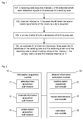
- Fig. 3 is a diagram of a massive planar single-polarized antenna array according to an embodiment of the present disclosure, and Fig.
- FIG. 3 shows a single-polarized antenna array with a dimension of N v ⁇ N h , wherein the product of the antenna element number N v in a vertical direction and the antenna element number N h in a horizontal direction is equal to the antenna number N of a sending side.
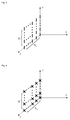
- Fig. 4 is a diagram of a massive planar dual-polarized antenna array according to an embodiment of the present disclosure, and Fig. 4 shows a dual-polarized antenna array with a dimension of N v ⁇ N h , wherein twice of the product of the antenna element number N v in a vertical direction and the antenna element number N h in a horizontal direction is equal to the antenna number N of a sending side.
- an antenna consists of at least one antenna array element with the same polarization direction, and the antenna may be equivalent to an antenna port in a Long Term Evolution (LTE) standard, wherein the antenna array element is a minimum component constituting the antenna.
- LTE Long Term Evolution
- channel information is a numerical indicator of a small-scale channel or a fast fading channel between a sending antenna and a receiving antenna.
- Fig. 5 is a diagram of antenna indexes of a planar single-polarized antenna array according to an embodiment of the present disclosure. As shown in Fig. 5 , antennae in the first row are indexed at first, sequentially being 1, 2, ..., n from right to left; then antennae in the second row are indexed, sequentially being n+1, n+2, ..., 2n from right to left, and so on, and the indexing is performed by row.
- Fig. 6 is a diagram of antenna indexes of a planar dual-polarized antenna array according to an embodiment of the present disclosure. As shown in Fig.
- antennae with a first polarization direction in the first row are indexed at first, sequentially being 1, 2, ..., n from right to left; then antennae with a second polarization direction in the first row are indexed, sequentially being n+1, n+2, ..., 2n from right to left; antennae with the first polarization direction in the second row are indexed next, sequentially being 2n+1, 2n+2, ..., 3n from right to left; antennae with the second polarization direction in the second row are indexed later on, sequentially being 3n+1, 3n+2, ..., 4n from right to left, and so on, and the indexing is performed by row by polarization.
- An embodiment of the present disclosure provides a method for acquiring channel information, which includes the following four steps.
- Step 1 indexes L of M antennae which send reference signals in N antennae are acquired, wherein N is the number of antennae of a sending side, and M is less than or equal to N.
- Step 2 channel information Y between the M antennae and a receiving antenna is acquired.
- Step 3 a unitary matrix W with a dimension of NxN is acquired.
- the information from the sending side is included in system or control information proprietary to a cell or a terminal, and includes, but not limited to, an antenna element number N v in a vertical direction, an antenna element number N h in a horizontal direction, a polarized antenna element indicator and related information about a polarized matrix W pol .
- W pol is a scalar "1"; and for a dual-polarized antenna element, W pol is a polarized matrix with a dimension of 2x2. Note: for a single-polarized antenna element, it is met that the product of N v and N h is N; and for a dual-polarized antenna element, it is met that twice of the product of N v and N h is N.
- Step 4 an estimate S' of channel information S between the N antennae and the receiving antenna is acquired according to the indexes L of the M antennae, the channel information Y between the M antennae and the receiving antenna and the unitary matrix W with the dimension of N ⁇ N.
- ⁇ represents the operation of calculating a norm of a vector
- s.t is a constraint condition mark
- H represents the operation of calculating the conjugate transpose of a matrix
- min(x) represents calculation of a variable value by which a value of X is minimized
- the sending side refers to a network side
- the receiving side refers to a terminal side.
- Fig. 8 is a diagram of antenna indexes of a single-polarized antenna array with a dimension of 8x8 according to an embodiment of the present disclosure. As shown in Fig. 8 , it is supposed that the number M of antennae which send reference signals is 10 ( ⁇ 64).
- a terminal side uses one receiving antenna.
- reference data of each antenna in the 10 antennae is a random sequence which is proprietary to the antenna and has an element modulus value of "1"
- the number of reference signal resource locations of each antenna is equal to the length of the reference data (or the random sequence)
- different antennae in the 10 antennae use the same or different reference signal resource locations, and for different antennae using the same reference signal resource locations, their reference data (random sequences) is orthogonal or approximately orthogonal, wherein the reference data is data which is sent at the reference signal resource locations and is known to a sender and a receiver, and the reference signal resource locations are time and/or frequency resource locations where the reference signals are sent.
- the terminal side acquires a random matrix P with a dimension of 10 ⁇ 64, wherein the 7th element in the 1th row of the random matrix P is "1", and other elements are 0"; the 15th element in the 2nd row is “1", and other elements are 0"; the 19th element in the 3rd row is “1", and other elements are 0"; the 28th element in the 4th row is "1", and other elements are 0", and so on, the 55th elements in the 10th row is "1", and other elements are 0".
- ⁇ represents operation of calculating a norm of a vector
- s.t is a constraint condition mark
- H represents operation of calculating the conjugate transpose of a matrix
- min(x) represents calculation of a variable value by which a value of X is minimized.
- Fig. 9 is a diagram of antenna indexes of a dual-polarized antenna array with a dimension of 8x8 according to an embodiment of the present disclosure. As shown in Fig. 9 , it is supposed that the number M of antennae which send reference signals is 20 ( ⁇ 128).
- a terminal side uses one receiving antenna.
- reference data of each antenna in the 20 antennae is a random sequence which is proprietary to the antenna and has an element modulus value of "1"
- the number of reference signal resource locations of each antenna is equal to the length of the reference data (or the random sequence)
- different antennae in the 20 antennae use the same or different reference signal resource locations, and for different antennae using the same reference signal resource locations, their reference data (random sequences) is orthogonal or approximately orthogonal, wherein the reference data is data which is sent at the reference signal resource locations and is known to a sender and a receiver, and the reference signal resource locations are time and/or frequency resource locations where the reference signals are sent.
- the terminal side acquires a random matrix P with a dimension of 20x128, wherein the 7th element in the 1st row of the random matrix P is "1", and other elements are 0"; the 17th element in the 2nd row is “1", and other elements are 0"; the 24th element in the 3rd row is “1", and other elements are 0"; the 32nd element in the 4th row is "1", and other elements are 0"; and following the same rule, the 126th elements in the 20th row is "1", and other elements are 0".
- ⁇ represents operation of calculating a norm of a vector
- s.t is a constraint condition mark
- H represents operation of calculating the conjugate transpose of a matrix
- min(x) represents calculation of a variable value by which a value of X is minimized.
- An embodiment of the present disclosure further provides a computer-readable storage medium, which includes a set of computer-executable instructions, the instructions being configured to execute the method for acquiring channel information of the embodiment of the present disclosure.
- the embodiments of the present disclosure may be provided as a method, a system or a computer program product. Therefore, the present disclosure may adopt a form of pure hardware embodiment, pure software embodiment and combined software and hardware embodiment. Moreover, the present disclosure may adopt a form of computer program product implemented on one or more computer-available storage media (including, but not limited to, a disk memory, a Compact Disc Read-Only Memory (CD-ROM) and an optical memory) including computer-available program codes.
- CD-ROM Compact Disc Read-Only Memory
- each flow and/or block in the flowcharts and/or the block diagrams and combinations of the flows and/or blocks in the flowcharts and/or the block diagrams may be implemented by computer program instructions.
- These computer program instructions may be provided for a universal computer, a dedicated computer, an embedded processor or a processor of other programmable data processing equipment to generate a machine, so that a device for realizing a function specified in one flow or more flows in the flowcharts and/or one block or more blocks in the block diagrams is generated by the instructions executed through the computer or the processor of the other programmable data processing equipment.
- These computer program instructions may also be stored in a computer-readable memory capable of guiding the computer or other programmable data processing equipment to work in a specific manner, so that a product including an instruction device may be generated by the instructions stored in the computer-readable memory, the instruction device realizing the function specified in one flow or many flows in the flowcharts and/or one block or many blocks in the block diagrams.
- These computer program instructions may further be loaded onto a computer or other programmable data processing equipment, so that a series of operating steps are executed on the computer or other programmable data processing equipment to generate processing implemented by the computer, and steps for realizing the function specified in one flow or many flows in the flowcharts and/or one block or many blocks in the block diagrams are provided by the instructions executed on the computer or the other programmable data processing equipment.
Abstract
Description
- The present disclosure relates to a transmission technology for massive antenna array, and in particular to a method and device for acquiring channel information for a receiving side in a wireless communication system employing a massive antenna array.
- Along with rise of smart terminals and mobile social networks, the requirements for mobile communication service traffic explosively increase. A Beyond Fourth Generation/Fifth Generation (B4G/5G) mobile communication system in the future will be confronted with a massive information transmission requirement and a ubiquitous coverage requirement. Adoption of an advanced multi-antenna technology, a channel adaptive technology and the like in a Fourth Generation (4G) mobile communication standard has made spectral efficiency of a system approach to channel capacity, and it is necessary to change a conventional network architecture and find a new radio resource growth point to achieve the purpose. Cell miniaturization and isomerization is a development trend of a wireless network in the future, and a distance between a terminal and an access point may be shortened to remarkably reduce path loss of a signal, thereby improving the spectral efficiency and power efficiency of the system and facilitating enhancement of network coverage; and however, a complex interference problem needs to be solved. On the other hand, configuration of a more massive antenna array is considered as another low-cost implementation manner capable of remarkably improving system capacity and coverage.
- A high-dimensional antenna arrangement-based massive antenna array technology is one of hot research directions which rise in recent two years. Latest researches have shown that: an adaptive massive antenna array technology may deeply excavate and utilize spatial radio resources, may remarkably improve spectral efficiency and power efficiency of a system theoretically, and is an important technology for constructing a high-performance green broadband mobile communication system in the future. But how to completely excavate its potential gain is urgent to be deeply researched. Moreover, adaptive massive antenna array transmission may present some new characteristics, for example: spatial distribution of channels is obviously sparse; massive array beams may almost completely eliminate influence of noise, but same-frequency interference caused by pilot pollution and the like becomes a major factor which restricts system performance; and performance of an adaptive massive antenna array mainly depends on a statistical characteristic of a channel, and influence of small-scale fading of the channel is obviously reduced.
- In order to design a novel efficient and reliable transmission technology for massive antenna array for adaptation to the characteristics, it is necessary to solve a problem about acquisition of channel information on a receiving side at first. Based on an existing method for acquiring channel information, sharp increase of the number of antennae on a sending side may inevitably cause sharp increase in overhead of reference signals configured for channel information acquisition, and in other words, the existing method for acquiring channel information inhibits further improvement in spectral efficiency of massive antenna array transmission. A problem about the overhead of the reference signal configured for channel information acquisition is a bottleneck problem, which is required to be solved, of a massive antenna array system. Therefore, seeking for a novel method for acquiring channel information applicable to a massive antenna array wireless communication system has high theoretical value and practical significance for construction of a practical massive antenna array transmission system.
- In order to solve the existing technical problem, the embodiments of the present disclosure provide a method and device for acquiring channel information.
- An embodiment of the present disclosure provides a method for acquiring channel information, which may include that:
- a receiving side acquires indexes L of M antennae which send reference signals in N antennae of a sending side;
- channel information Y between the M antennae and a receiving antenna of the receiving side is acquired;
- a unitary matrix W with a dimension of NxN is acquired; and
- an estimate S' of channel information S between the N antennae of the sending side and the receiving antenna of the receiving side is determined by virtue of the indexes L, the unitary matrix W and the channel information Y.
- Preferably, the step that the receiving side acquires the indexes L of the M antennae which send the reference signals in the N antennae of the sending side may include that:
- the receiving side acquires intrinsic indexes L of the M antennae, or acquires the indexes L of the M antennae according to time and/or frequency resource locations, or acquires the indexes L of the M antennae through first system or control information from the sending side.
- Preferably, the receiving side may directly acquire the indexes L of the M antennae in the first system or control information, or acquire the indexes L of the M antennae through antenna array indexes in the first system or control information.
- Preferably, the step that the channel information Y between the M antennae and the receiving antenna of the receiving side is acquired may include that:
- the receiving side acquires channel information {y1,y2,......,yM} between each antenna in the M antennae and the receiving antenna according to reference data and received data at a reference signal resource location of each antenna in the M antennae; and
- the channel information {y1,y2,......,yM} between each antenna in the M antennae and the receiving antenna is combined to obtain the channel information Y.
- Preferably, the step that the unitary matrix W with the dimension of NxN is acquired may include that:
- the receiving side acquires the unitary matrix W which is predetermined, or determines the unitary matrix W through second system or control information from the sending side.
- Preferably, the unitary matrix W which is predetermined may be a Discrete Fourier Transform (DFT) matrix with a dimension of NxN, and each element of the unitary matrix W may be:

- Preferably, the second system or control information may include an antenna element number Nv in a vertical direction, an antenna element number Nh in a horizontal direction, a polarized antenna element indicator and related information about a polarized matrix Wpol.
- Preferably, the step that the unitary matrix W is determined through the second system or control information from the sending side may include that:
- the unitary matrix W with the dimension of NxN is determined by calculating a kronecker product of a DFT matrix Wv with a dimension of Nvx×Nv in the vertical direction, the polarized matrix Wpol and a DFT matrix Wh with a dimension of Nh×Nh in the horizontal direction,
- wherein when it is determined, according to the polarized antenna element indicator, that the N antennae of the sending side are single-polarized antenna elements, a product of Nv and Nh is N and Wpol is a
scalar 1; and when it is determined, according to the polarized antenna element indicator, that the N antennae of the sending side are dual-polarized antenna elements, twice of the product of Nv and Nh is N and Wpol is a polarized matrix with a dimension of 2×2. - Preferably, the step that the estimate S' of the channel information S between the N antennae of the sending side and the receiving antenna of the receiving side is determined by virtue of the indexes L, the unitary matrix W and the channel information Y may include that:
- the receiving side acquires a random matrix P with a dimension of MxN by virtue of the indexes L;
- a vector X is determined by virtue of the random matrix P, the unitary matrix W and the channel information Y; and
- the estimate S' of the channel information S between the N antennae and the receiving antenna is determined by virtue of the unitary matrix W and the vector X.
- Preferably, an imth element in an mth row of the random matrix P may be 1 and other elements may be 0, wherein the im is an antenna index of the mth antenna in the M antennae, and m=1,2,...,M.
- Preferably, the vector X may be a vector with a smallest norm in a vector set {V1,V2,...,VK}, wherein any vector Vi in the vector set {V1,V2,...,VK} meets that: a product of the random matrix P, the unitary matrix W or a conjugate transpose of the unitary matrix W and the vector Vi is equal to the channel information Y, and the norm is a sum of absolute values of all elements of the vector.
- Preferably, the estimate S' of the channel information S between the N antennae and the receiving antenna may be determined by calculating a product of the unitary matrix W or the conjugate transpose of the unitary matrix W and the vector X.
- An embodiment of the present disclosure further provides a device for acquiring channel information, which may include:
- an information acquisition module, configured to acquire indexes L of M antennae which send reference signals in N antennae of a sending side, acquire channel information Y between the M antennae and a receiving antenna of a receiving side, and acquire a unitary matrix W with a dimension of NxN; and
- a channel information estimation module, configured to determine an estimate S' of channel information S between the N antennae of the sending side and the receiving antenna of the receiving side by virtue of the indexes L, the unitary matrix W and the channel information Y.
- Preferably, the channel information acquisition module may include an antenna index acquisition sub-module, a channel information acquisition sub-module and a unitary matrix acquisition sub-module, wherein
the antenna index acquisition sub-module may be configured to acquire intrinsic indexes L of the M antennae, or acquire the indexes L of the M antennae according to time and/or frequency resource locations, or acquire the indexes L of the M antennae through first system or control information from the sending side;
the channel information acquisition sub-module may be configured to acquire channel information {y1,y2,......,yM} between each antenna in the M antennae and the receiving antenna according to reference data and received data at a reference signal resource location of each antenna in the M antennae, and combine the channel information {y1,y2,......,yM} between each antenna in the M antennae and the receiving antenna to obtain the channel information Y; and
the unitary matrix acquisition sub-module may be configured to acquire the unitary matrix W which is predetermined, or determine the unitary matrix W through second system or control information from the sending side. - Preferably, the second system or control information may include an antenna element number Nv in a vertical direction, an antenna element number Nh in a horizontal direction, a polarized antenna element indicator and related information about a polarized matrix Wpol.
- Preferably, the operation that the unitary matrix acquisition sub-module determines the unitary matrix W through the second system or control information from the sending side may include that:
- the unitary matrix acquisition sub-module determines the unitary matrix W with the dimension of NxN by calculating a kronecker product of a DFT matrix Wv with a dimension of Nvx×Nv in the vertical direction, the polarized matrix Wpol and a DFT matrix Wh with a dimension of Nh×Nh in the horizontal direction,
- wherein when it is determined, according to the polarized antenna element indicator, that the N antennae of the sending side are single-polarized antenna elements, a product of Nv and Nh is N and Wpol is a
scalar 1; and when it is determined, according to the polarized antenna element indicator, that the N antennae of the sending side are dual-polarized antenna elements, twice of the product of Nv and Nh is N and Wpol is a polarized matrix with a dimension of 2x2. - Preferably, the channel information estimation module may include a random matrix acquisition sub-module, a vector determination sub-module and an estimation sub-module, wherein
the random matrix acquisition sub-module may be configured to acquire a random matrix P with a dimension of MxN by virtue of the indexes L;
the vector determination sub-module may be configured to determine a vector X by virtue of the random matrix P, the unitary matrix W and the channel information Y; and
the estimation sub-module may be configured to determine the estimate S' of the channel information S between the N antennae and the receiving antenna by virtue of the unitary matrix W and the vector X. - Preferably, an imth element in an mth row of the random matrix P is 1 and other elements are 0, wherein the im is an antenna index of the mth antenna in the M antennae, and m=1,2,...,M.
- Preferably, the vector X may be a vector with a smallest norm in a vector set {V1,V2,...,VK}, wherein any vector Vi in the vector set {V1,V2,...,VK} meets that: a product of the random matrix P, the unitary matrix W or conjugate transpose of the unitary matrix W and the vector Vi is equal to the channel information Y, and the norm is a sum of absolute values of all elements of the vector.
- Preferably, the estimation sub-module may be configured to determine the estimate S' of the channel information S between the N antennae and the receiving antenna by calculating a product of the unitary matrix W or a conjugate transpose of the unitary matrix W and the vector X.
- An embodiment of the present disclosure further provides a computer-readable storage medium, which may include a set of computer-executable instructions, the instructions being configured to execute the method for acquiring channel information of the embodiment of the present disclosure.
- Compared with a related art, the embodiments of the present disclosure have beneficial effects as follows:
- according to the embodiments of the present disclosure, the estimate S' of channel information S between N antennae and a receiving antenna is acquired according to channel information Y between M antennae which send reference signals in the N antennae and the receiving antenna, which reduces overhead of the reference signals, used for channel information acquisition, of a massive antenna array, thereby further improving spectral efficiency of massive antenna array transmission.
-
-
Fig. 1 is a flowchart of a method for acquiring channel information according to an embodiment of the present disclosure; -
Fig. 2 is a structure diagram of a device for acquiring channel information according to an embodiment of the present disclosure; -
Fig. 3 is a diagram of a massive planar single-polarized antenna array according to an embodiment of the present disclosure; -
Fig. 4 is a diagram of a massive planar dual-polarized antenna array according to an embodiment of the present disclosure; -
Fig. 5 is a diagram of antenna indexes of a planar single-polarized antenna array according to an embodiment of the present disclosure; -
Fig. 6 is a diagram of antenna indexes of a planar dual-polarized antenna array according to an embodiment of the present disclosure; -
Fig. 7 is a diagram of mapping of antenna groups to time and/or frequency resources according to an embodiment of the present disclosure; -
Fig. 8 is a diagram of antenna indexes of a single-polarized antenna array with a dimension of 8x8 according to an embodiment of the present disclosure; and -
Fig. 9 is a diagram of antenna indexes of a dual-polarized antenna array with a dimension of 8x8 according to an embodiment of the present disclosure. - Preferred embodiments of the present disclosure are described below with reference to the drawings in detail, and it should be understood that the preferred embodiments described below are only adopted to describe and explain the present disclosure and not intended to limit the present disclosure.
-
Fig. 1 is a flowchart of a method for acquiring channel information according to an embodiment of the present disclosure. As shown inFig. 1 , the method includes: - step 101: a receiving side acquires indexes L of M antennae which send reference signals in N antennae of a sending side. Specifically, the receiving side acquires intrinsic indexes L of the M antennae, that is, the indexes L are kept unchanged along with changes of time and/or frequency resource locations; or the receiving side acquires the indexes L of the M antennae in a predetermined manner according to the time and/or frequency resource locations; or the receiving side acquires the indexes L of the M antennae through first system or control information from the sending side, that is, the receiving side directly acquires the indexes L of the M antennae from the first system or control information, or acquires the indexes L of the M antennae through antenna array indexes in the first system or control system;
- step 102: channel information Y between the M antennae and a receiving antenna of the receiving side is acquired; specifically, the receiving side acquires channel information {y1,y2,......,yM} between each antenna in the M antennae and the receiving antenna according to reference data and received data at a reference signal resource location (i.e. the time and/or frequency resource locations of the reference signals) of each antenna in the M antennae, and then combines the channel information {y1,y2,......,yM} between each antenna in the M antennae and the receiving antenna to obtain the channel information Y, wherein the reference data is transmitted data at the known time and/or frequency resource locations of the reference signals of each antenna in the M antennae of the receiving side;
- step 103: the receiving side acquires a unitary matrix W with a dimension of NxN; specifically, the receiving side acquires the unitary matrix W which is predetermined, or determines the unitary matrix W through second system or control information from the sending side; the unitary matrix W which is predetermined is a DFT matrix with a dimension of NxN, and each element of the unitary matrix W is:

- The second system or control information includes an antenna element number Nv in a vertical direction, an antenna element number Nh in a horizontal direction, a polarized antenna element indicator and related information about a polarized matrix Wpol, and the receiving side determines the unitary matrix W with the dimension of NxN by calculating a kronecker product of a DFT matrix Wv with a dimension of Nvx×Nv in the vertical direction, the polarized matrix Wpol and a DFT matrix Wh with a dimension of Nh×Nh in the horizontal direction, wherein, when it is determined, according to the polarized antenna element indicator, that the N antennae of the sending side are single-polarized antenna elements, a product of Nv and Nh is N and Wpol is a scalar 1; and when it is determined, according to the polarized antenna element indicator, that the N antennae of the sending side are dual-polarized antenna elements, twice of the product of Nv and Nh is N and Wpol is a polarized matrix with a dimension of 2x2; and
step 104: the receiving side determines an estimate S' of channel information S between the N antennae of the sending side and the receiving antenna of the receiving side by virtue of the indexes L, the unitary matrix W and the channel information Y; specifically, the receiving side acquires a random matrix with a dimension of MxN by virtue of the indexes L of the M antennae, the imth element in the mth row of the random matrix P being 1 and other elements being 0, wherein im is an antenna index of the mth antenna in the M antennae, and m=1,2,...,M; then a vector X is determined by virtue of the random matrix P, the unitary matrix W and the channel information Y, the vector X being a vector with a smallest norm in a vector set {V1,V2,...,VK}, wherein any vector Vi in the vector set {V1,V2,...,VK} meets that: a product of the random matrix P, the unitary matrix W or the conjugate transpose of the unitary matrix W and the vector Vi is equal to the channel information Y, and the norm is a sum of absolute values of all elements of the vector; and finally, the estimate S' of the channel information S between the N antennae and the receiving antenna is determined by virtue of the unitary matrix W and the vector X, and preferably, the estimate S' of the channel information S between the N antennae and the receiving antenna is determined by calculating a product of the unitary matrix W or the conjugate transpose of the unitary matrix W and the vector X. - An embodiment of the present disclosure further provides a device for acquiring channel information. As shown in
Fig. 2 , the device includes aninformation acquisition module 10 and a channelinformation estimation module 20, wherein: - the
information acquisition module 10 is configured to acquire indexes L of M antennae which send reference signals in N antennae of a sending side, acquire channel information Y between the M antennae and a receiving antenna of a receiving side, and acquire a unitary matrix W with a dimension of NxN. - Here, the
information acquisition module 10 includes an antennaindex acquisition sub-module 11, a channelinformation acquisition sub-module 12 and a unitarymatrix acquisition sub-module 13. - The antenna
index acquisition sub-module 11 is configured to acquire intrinsic indexes L of the M antennae, or acquire the indexes L of the M antennae according to time and/or frequency resource locations, or acquire the indexes L of the M antennae through first system or control information from the sending side;
the channelinformation acquisition sub-module 12 is configured to acquire channel information {y1,y2,......,yM} between each antenna in the M antennae and the receiving antenna according to reference data and received data at a reference signal resource location of each antenna in the M antennae, and combine the channel information {y1,y2,......,yM} between each antenna in the M antennae and the receiving antenna to obtain the channel information Y; and
the unitarymatrix acquisition sub-module 13 is configured to acquire the unitary matrix W which is predetermined, or determine the unitary matrix W through second system or control information from the sending side. - The channel
information estimation module 20 is configured to determine an estimate S' of channel information S between the N antennae of the sending side and the receiving antenna of the receiving side by virtue of the indexes L, the unitary matrix W and the channel information Y. - The channel
information estimation module 20 includes a randommatrix acquisition sub-module 21, avector determination sub-module 22 and anestimation sub-module 23. - The random
matrix acquisition sub-module 21 is configured to acquire a random matrix P with a dimension of MxN by virtue of the indexes L of the M antennae, the imth element in the mth row of the random matrix P being 1 and other elements being 0, wherein im is an antenna index of the mth antenna in the M antennae, and m=1,2,...,M;
thevector determination sub-module 22 is configured to determine a vector X by virtue of the random matrix P, the unitary matrix W and the channel information Y, where the vector X is a vector with a smallest norm in a vector set {V1,V2,...,VK} and a product of the random matrix P, the unitary matrix W or the conjugate transpose of the unitary matrix W and any vector Vi in the vector set {V1,V2,...,VK} is equal to the channel information Y; and
theestimation sub-module 23 is configured to determine the estimate S' of the channel information S between the N antennae and the receiving antenna by virtue of the unitary matrix W and the vector X. - It is to be noted that the
information acquisition module 10 and the channelinformation estimation module 20 may be implemented by a Central Processing Unit (CPU), a Micro Processing Unit (MPU), a Digital Signal Processor (DSP) or a Field Programmable Gate Array (FPGA) in the device for acquiring channel information. - The present disclosure is further elaborated below with reference to
Fig. 3 to Fig. 9 and specific embodiments. It is to be noted that the embodiments in the present disclosure and characteristics in the embodiments can be combined if there is no conflict. - It is supposed that an antenna array consists of a plurality of antenna elements and the dimension of the antenna array is Nv×Nh, that is, the number of antenna elements in a vertical direction or the number of rows of the antenna elements is Nv, and the number of antenna elements in a horizontal direction or the number of columns of the antenna elements is Nh.
- It is supposed that the antenna elements are divided into single-polarized antenna elements and dual-polarized antenna elements, wherein each single-polarized antenna element is equivalent to one antenna, and an antenna array consisting of single-polarized antenna elements is called a single-polarized antenna array; and each dual-polarized antenna element is equivalent to two antennae with different polarization directions, and an antenna array consisting of dual-polarized antenna elements is called a dual-polarized antenna array.
Fig. 3 is a diagram of a massive planar single-polarized antenna array according to an embodiment of the present disclosure, andFig. 3 shows a single-polarized antenna array with a dimension of Nv×Nh, wherein the product of the antenna element number Nv in a vertical direction and the antenna element number Nh in a horizontal direction is equal to the antenna number N of a sending side.Fig. 4 is a diagram of a massive planar dual-polarized antenna array according to an embodiment of the present disclosure, andFig. 4 shows a dual-polarized antenna array with a dimension of Nv×Nh, wherein twice of the product of the antenna element number Nv in a vertical direction and the antenna element number Nh in a horizontal direction is equal to the antenna number N of a sending side. - It is supposed that an antenna consists of at least one antenna array element with the same polarization direction, and the antenna may be equivalent to an antenna port in a Long Term Evolution (LTE) standard, wherein the antenna array element is a minimum component constituting the antenna.
- It is supposed that channel information is a numerical indicator of a small-scale channel or a fast fading channel between a sending antenna and a receiving antenna.
-
Fig. 5 is a diagram of antenna indexes of a planar single-polarized antenna array according to an embodiment of the present disclosure. As shown inFig. 5 , antennae in the first row are indexed at first, sequentially being 1, 2, ..., n from right to left; then antennae in the second row are indexed, sequentially being n+1, n+2, ..., 2n from right to left, and so on, and the indexing is performed by row..Fig. 6 is a diagram of antenna indexes of a planar dual-polarized antenna array according to an embodiment of the present disclosure. As shown inFig. 6 , antennae with a first polarization direction in the first row are indexed at first, sequentially being 1, 2, ..., n from right to left; then antennae with a second polarization direction in the first row are indexed, sequentially being n+1, n+2, ..., 2n from right to left; antennae with the first polarization direction in the second row are indexed next, sequentially being 2n+1, 2n+2, ..., 3n from right to left; antennae with the second polarization direction in the second row are indexed later on, sequentially being 3n+1, 3n+2, ..., 4n from right to left, and so on, and the indexing is performed by row by polarization. - An embodiment of the present disclosure provides a method for acquiring channel information, which includes the following four steps.
- Step 1: indexes L of M antennae which send reference signals in N antennae are acquired, wherein N is the number of antennae of a sending side, and M is less than or equal to N.
- 1: A receiving side may acquire intrinsic indexes L of the M antennae, wherein the M antennae which send the reference signals in the N antennae may not change along with time and/or frequency.
- 2: The receiving side may acquire the indexes L of the M antennae in a predetermined manner, and at this moment, the indexes L of the M antennae are related to time and/or frequency resource locations. For example, the N antennae may be grouped, each antenna group includes M antennae, and the antennae in different groups are allowed to be partially overlapped; and then, the antenna groups are periodically mapped to corresponding time and/or frequency resources.
Fig. 7 is a diagram of mapping of antenna groups to time and/or frequency resources according to an embodiment of the present disclosure. As shown inFig. 7 , there are totally 20 antenna groups, and the antenna groups are mapped by taking a duration of 10 sub-frames as a period. Preferably, it is supposed that N is an integral multiple of M, the N antennae are divided into N/M groups, specifically, every M antennae are sequentially selected to form an antenna group at an interval of N/M, and the N/M antenna groups are cyclically mapped to the corresponding time and/or frequency resources. - 3:The indexes L of the M antennae are acquired by receiving information from the sending side, wherein the information from the sending side includes, but not limited to, the indexes L (i1,i2,...,iM) of each antenna in the M antennae and indexes of the antenna groups, and is included in system or control information proprietary to a cell or a terminal.
- Step 2: channel information Y between the M antennae and a receiving antenna is acquired.
- Specifically, the receiving side acquires channel information y1 between the first antenna in the M antennae and the receiving antenna according to reference data of the first antenna and received data at a reference signal resource location of the first antenna in the M antennae, acquires channel information y2 between the second antenna in the M antennae and the receiving antenna according to reference data of the second antenna and received data at a reference signal resource location of the second antenna in the M antennae and the receiving antenna, acquires, in the same manner, channel information yM between the Mth antenna in the M antennae and the receiving antenna according to reference data of the Mth antenna and received data at a reference signal resource location of the Mth antenna in the M antennae, and finally acquires the channel information Y between the M antennae and the receiving antenna, the channel information Y being a combination of the channel information between each antenna in the M antennae and the receiving antennae, i.e.,

- Step 3: a unitary matrix W with a dimension of NxN is acquired.
- 1: A predetermined unitary matrix W with the dimension of NxN is acquired.
The unitary matrix W with the dimension of NxN is a DFT matrix, that is, elements of the unitary matrix W meet the following formula:
- 2: The unitary matrix W with the dimension of N×N is acquired by receiving information from the sending side.
- Specifically, the information from the sending side is included in system or control information proprietary to a cell or a terminal, and includes, but not limited to, an antenna element number Nv in a vertical direction, an antenna element number Nh in a horizontal direction, a polarized antenna element indicator and related information about a polarized matrix Wpol.
- The unitary matrix W with the dimension of N×N is a kronecker product of a DFT matrix Wv in the vertical direction, the polarized matrix Wpol and a DFT matrix Wh in the horizontal direction; a specific formula is as follows:

- Step 4: an estimate S' of channel information S between the N antennae and the receiving antenna is acquired according to the indexes L of the M antennae, the channel information Y between the M antennae and the receiving antenna and the unitary matrix W with the dimension of N×N.
- Specifically, a random matrix P is acquired according to the indexes L of the M antennae at first, the random matrix P meeting the following characteristics that: a dimension is MxN, the imth (m=1,2,3,...,M) element in the mth row of the random matrix P is 1 and other elements are 0, wherein im is an antenna index of the mth antenna in the M antennae; then, a vector X is acquired according to the random matrix P, the unitary matrix W and the channel information Y between the M antennae and the receiving antenna, the vector X being a vector with a smallest norm in a vector set {V1,...,Vi,...,VK} and the norm referring to a sum of absolute values of all elements of the vector, wherein any vector Vi in the vector set {V1,...,Vi,...,VK} meets that: the product of the random matrix P, the unitary matrix W or the conjugate transpose of the unitary matrix W and the vector Vi is equal to the channel information Y between the M antennae and the receiving antenna, and X may be represented by a formula as follows:


- The sending side refers to a network side, and the receiving side refers to a terminal side.
- It is assumed that a network side uses a single-polarized antenna array with a dimension of 8x8, the number N of antennae of the network side is 8x8=64.
Fig. 8 is a diagram of antenna indexes of a single-polarized antenna array with a dimension of 8x8 according to an embodiment of the present disclosure. As shown inFig. 8 , it is supposed that the number M of antennae which send reference signals is 10 (<<64). - It is supposed that a terminal side uses one receiving antenna.
- The terminal side acquires intrinsic indexes L of the 10 antennae which send reference signals, or acquires the indexes L of the 10 antennae which send reference signals in a predetermined manner, or acquires the indexes L of the 10 antennae which send reference signals by receiving information from the network side, and it is supposed that the acquired indexes L of the 10 antennae are as follows:

- It is supposed that reference data of each antenna in the 10 antennae is a random sequence which is proprietary to the antenna and has an element modulus value of "1", the number of reference signal resource locations of each antenna is equal to the length of the reference data (or the random sequence), different antennae in the 10 antennae use the same or different reference signal resource locations, and for different antennae using the same reference signal resource locations, their reference data (random sequences) is orthogonal or approximately orthogonal, wherein the reference data is data which is sent at the reference signal resource locations and is known to a sender and a receiver, and the reference signal resource locations are time and/or frequency resource locations where the reference signals are sent.
- The terminal side acquires channel information y1 between the first antenna in the 10 antennae and the receiving antenna according to the reference data of the first antenna and received data at the reference signal resource locations of the first antenna in the 10 antennae, and specifically, the channel information y1 between the first antenna and the receiving antenna is an element mean value of vectors obtained by multiplying the conjugate of the reference data of the first antenna with the received data at the reference signal resource locations of the antenna upon element; similarly, channel information (y2,y3,...,y10) between the other 9 antennae in the 10 antennae and the receiving antenna is acquired in the same manner; and channel information Y between the 10 antennae and the receiving antenna is a combination of the channel information between each antenna in the 10 antennae and the receiving antenna, i.e.

- The terminal side acquires a predetermined unitary matrix W with a dimension of 64x64, and its elements meet:

- Or, the terminal side acquires the unitary matrix W with the dimension of 64x64 by receiving information from the network side, and the unitary matrix W with the dimension of 64x64 is a kronecker product of a DFT matrix in a vertical direction, a polarized matrix and a DFT matrix in a horizontal direction, and a formula is as follows:


- According to the known indexes L of the 10 antennae, the terminal side acquires a random matrix P with a dimension of 10×64, wherein the 7th element in the 1th row of the random matrix P is "1", and other elements are 0"; the 15th element in the 2nd row is "1", and other elements are 0"; the 19th element in the 3rd row is "1", and other elements are 0"; the 28th element in the 4th row is "1", and other elements are 0", and so on, the 55th elements in the 10th row is "1", and other elements are 0". Then, the terminal side acquires a vector X according to the random matrix P, the unitary matrix W and the channel information Y between the 10 antennae and the receiving antenna, the vector X being a vector with a smallest norm in a vector set {V1,...,Vi,...,VK} and any vector Vi in the vector set {V1,...,Vi,...,VK} meeting that: the product of the random matrix P, the unitary matrix W or the conjugate transpose of the unitary matrix W and the vector Vi is equal to the channel information Y between the 10 antennae and the receiving antenna, wherein the norm refers to the sum of absolute values of all elements of the vector, and X may be represented by a formula as follows:

- The terminal side acquires an estimate S' of channel information S between the 64 antennae and the receiving antenna according to the vector X and the unitary matrix W, wherein the estimate S' of the channel information S between the 64 antennae and the receiving antenna is equal to the product of the unitary matrix W or the conjugate transpose of the unitary matrix W and the vector X, and may be represented by a formula as follows:

- It is supposed that a network side uses a dual-polarized antenna array with a dimension of 8x8, the number N of antennae of the network side is 2×8×8=128.
Fig. 9 is a diagram of antenna indexes of a dual-polarized antenna array with a dimension of 8x8 according to an embodiment of the present disclosure. As shown inFig. 9 , it is supposed that the number M of antennae which send reference signals is 20 (<<128). - It is supposed that a terminal side uses one receiving antenna.
- The terminal side acquires intrinsic indexes L of the 20 antennae which send reference signals, or acquires the indexes L of the 20 antennae which send reference signals in a predetermined manner, or acquires the indexes L of the 20 antennae which send reference signals by receiving information from the network side, and it is supposed that the acquired indexes L of the 20 antennae are as follows:

- It is supposed that reference data of each antenna in the 20 antennae is a random sequence which is proprietary to the antenna and has an element modulus value of "1", the number of reference signal resource locations of each antenna is equal to the length of the reference data (or the random sequence), different antennae in the 20 antennae use the same or different reference signal resource locations, and for different antennae using the same reference signal resource locations, their reference data (random sequences) is orthogonal or approximately orthogonal, wherein the reference data is data which is sent at the reference signal resource locations and is known to a sender and a receiver, and the reference signal resource locations are time and/or frequency resource locations where the reference signals are sent.
- The terminal side acquires channel information y1 between the first antenna in the 20 antennae and the receiving antenna according to the reference data of the first antenna and received data at the reference signal resource locations of the first antenna in the 20 antennae, and specifically, the channel information y1 between the first antenna and the receiving antenna is an element mean value of vectors obtained by multiplying the conjugate of the reference data of the first antenna with the received data at the reference signal resource locations of the antenna upon element; similarly, channel information (y2,y3,...,y20) between the other 19 antennae in the 20 antennae and the receiving antenna is acquired in the same manner; and channel information Y, acquired by the terminal side, between the 20 antennae and the receiving antenna is a combination of the channel information between each antenna in the 20 antennae and the receiving antenna, i.e.

- A predetermined unitary matrix W with a dimension of 128x128 is acquired, and its elements meet:

- Or, the terminal side acquires the unitary matrix W with the dimension of 128x128 by receiving information from the network side, and the unitary matrix W with the dimension of 128x128 is a kronecker product of a DFT matrix in a vertical direction, a polarized matrix and a DFT matrix in a horizontal direction, and a formula is as follows:


- According to the known indexes L of the 20 antennae, the terminal side acquires a random matrix P with a dimension of 20x128, wherein the 7th element in the 1st row of the random matrix P is "1", and other elements are 0"; the 17th element in the 2nd row is "1", and other elements are 0"; the 24th element in the 3rd row is "1", and other elements are 0"; the 32nd element in the 4th row is "1", and other elements are 0"; and following the same rule, the 126th elements in the 20th row is "1", and other elements are 0". Then, the terminal side acquires a vector X according to the random matrix P, the unitary matrix W and the channel information Y between the 20 antennae and the receiving antenna, wherein the vector X is a vector with a smallest norm in a vector set {V1,...,Vi,...,VK} and any vector Vi in the vector set {V1,...,Vi,...,VK} meets that: the product of the random matrix P, the unitary matrix W or the conjugate transpose of the unitary matrix W and the vector Vi is equal to the channel information Y between the 20 antennae and the receiving antenna, wherein the norm refers to the sum of absolute values of all elements of the vector, and X may be represented by a formula as follows:

- The terminal side acquires an estimate S' of channel information S between the 128 antennae and the receiving antenna according to the vector X and the unitary matrix W, wherein the estimate S' of the channel information S between the 128 antennae and the receiving antenna is equal to the product of the unitary matrix W or the conjugate transpose of the unitary matrix W and the vector X, and may be represented by a formula as follows:

- An embodiment of the present disclosure further provides a computer-readable storage medium, which includes a set of computer-executable instructions, the instructions being configured to execute the method for acquiring channel information of the embodiment of the present disclosure.
- Those skilled in the art should know that the embodiments of the present disclosure may be provided as a method, a system or a computer program product. Therefore, the present disclosure may adopt a form of pure hardware embodiment, pure software embodiment and combined software and hardware embodiment. Moreover, the present disclosure may adopt a form of computer program product implemented on one or more computer-available storage media (including, but not limited to, a disk memory, a Compact Disc Read-Only Memory (CD-ROM) and an optical memory) including computer-available program codes.
- The present disclosure is described with reference to flowcharts and/or block diagrams of the method, equipment (system) and computer program product according to the embodiments of the present disclosure. It should be understood that each flow and/or block in the flowcharts and/or the block diagrams and combinations of the flows and/or blocks in the flowcharts and/or the block diagrams may be implemented by computer program instructions. These computer program instructions may be provided for a universal computer, a dedicated computer, an embedded processor or a processor of other programmable data processing equipment to generate a machine, so that a device for realizing a function specified in one flow or more flows in the flowcharts and/or one block or more blocks in the block diagrams is generated by the instructions executed through the computer or the processor of the other programmable data processing equipment.
- These computer program instructions may also be stored in a computer-readable memory capable of guiding the computer or other programmable data processing equipment to work in a specific manner, so that a product including an instruction device may be generated by the instructions stored in the computer-readable memory, the instruction device realizing the function specified in one flow or many flows in the flowcharts and/or one block or many blocks in the block diagrams.
- These computer program instructions may further be loaded onto a computer or other programmable data processing equipment, so that a series of operating steps are executed on the computer or other programmable data processing equipment to generate processing implemented by the computer, and steps for realizing the function specified in one flow or many flows in the flowcharts and/or one block or many blocks in the block diagrams are provided by the instructions executed on the computer or the other programmable data processing equipment.
- The above are only the preferred embodiments of the present disclosure and not intended to limit the present disclosure. For those skilled in the art, the present disclosure may have various modifications and variations. Any modification, equivalent replacement, improvement and the like made within the spirit and principle of the present disclosure shall fall within the scope of protection of the present disclosure.
- Although the present disclosure is described above in detail, the present disclosure is not limited to the above description, and those skilled in the art may make various modifications according to the principle of the present disclosure. Therefore, all modifications made according to the principle of the present disclosure shall be understood to fall within the scope of protection of the present disclosure.
Claims (21)
- A method for acquiring channel information, comprising:acquiring, by a receiving side, indexes L of M antennae which send reference signals in N antennae of a sending side;acquiring channel information Y between the M antennae and a receiving antenna of the receiving side;acquiring a unitary matrix W with a dimension of NxN; anddetermining an estimate S' of channel information S between the N antennae of the sending side and the receiving antenna of the receiving side by virtue of the indexes L, the unitary matrix W and the channel information Y.
- The method according to claim 1, wherein the step of acquiring, by the receiving side, the indexes L of the M antennae which send the reference signals in the N antennae of the sending side comprises:acquiring, by the receiving side, intrinsic indexes L of the M antennae, or acquiring the indexes L of the M antennae according to time and/or frequency resource locations, or acquiring the indexes L of the M antennae through first system or control information from the sending side.
- The method according to claim 2, wherein the receiving side directly acquires the indexes L of the M antennae from the first system or control information, or acquires the indexes L of the M antennae through antenna array indexes in the first system or control information.
- The method according to claim 1, wherein the step of acquiring the channel information Y between the M antennae and the receiving antenna of the receiving side comprises:acquiring, by the receiving side, channel information {y1,y2,......,yM} between each antenna in the M antennae and the receiving antenna according to reference data and received data at a reference signal resource location of each antenna in the M antennae; andcombining the channel information {y1,y2,......,yM} between each antenna in the M antennae and the receiving antenna to obtain the channel information Y.
- The method according to claim 1, wherein the step of acquiring the unitary matrix W with the dimension of N×N comprises:acquiring, by the receiving side, the unitary matrix W which is predetermined, or determining the unitary matrix W through second system or control information from the sending side.
- The method according to claim 5, wherein the unitary matrix W which is predetermined is a Discrete Fourier Transform (DFT) matrix with a dimension of N×N, and each element of the unitary matrix W is:

- The method according to claim 5, wherein the second system or control information comprises an antenna element number Nv in a vertical direction, an antenna element number Nh in a horizontal direction, a polarized antenna element indicator and related information about a polarized matrix Wpol.
- The method according to claim 7, wherein the step of determining the unitary matrix W through the second system or control information from the sending side comprises:determining the unitary matrix W with the dimension of NxN by calculating a kronecker product of a DFT matrix Wv with a dimension of Nv×Nv in the vertical direction, the polarized matrix Wpol and a DFT matrix Wh with a dimension of Nh×Nh in the horizontal direction;wherein when it is determined, according to the polarized antenna element indicator, that the N antennae of the sending side are single-polarized antenna elements, a product of Nv and Nh is N and Wpol is a scalar 1; and when it is determined, according to the polarized antenna element indicator, that the N antennae of the sending side are dual-polarized antenna elements, twice of the product of Nv and Nh is N and Wpol is a polarized matrix with a dimension of 2x2.
- The method according to claim 1, wherein the step of determining the estimate S' of the channel information S between the N antennae of the sending side and the receiving antenna of the receiving side by virtue of the indexes L, the unitary matrix W and the channel information Y comprises:acquiring, by the receiving side, a random matrix P with a dimension of MxN by virtue of the indexes L;determining a vector X by virtue of the random matrix P, the unitary matrix W and the channel information Y; anddetermining the estimate S' of the channel information S between the N antennae and the receiving antenna by virtue of the unitary matrix W and the vector X.
- The method according to claim 9, wherein an imth element in an mth row of the random matrix P is 1 and other elements are 0, wherein the im is an antenna index of the mth antenna in the M antennae, and m=1,2,...,M.
- The method according to claim 10, wherein the vector X is a vector with a smallest norm in a vector set {V1,V2,...,VK}, wherein any vector Vi in the vector set {V1,V2,...,VK} meets that: a product of the random matrix P, the unitary matrix W or a conjugate transpose of the unitary matrix W and the vector Vi is equal to the channel information Y, and the norm is a sum of absolute values of all elements of the vector.
- The method according to any one of claims 9 to 11, wherein determining the estimate S' of the channel information S between the N antennae and the receiving antenna by virtue of the unitary matrix W and the vector X comprises:determining the estimate S' of the channel information S between the N antennae and the receiving antenna by calculating a product of the unitary matrix W or a conjugate transpose of the unitary matrix W and the vector X.
- A device for acquiring channel information, comprising:an information acquisition module, configured to acquire indexes L of M antennae which send reference signals in N antennae of a sending side, acquire channel information Y between the M antennae and a receiving antenna of a receiving side, and acquire a unitary matrix W with a dimension of N×N; anda channel information estimation module, configured to determine an estimate S' of channel information S between the N antennae of the sending side and the receiving antenna of the receiving side by virtue of the indexes L, the unitary matrix W and the channel information Y.
- The device according to claim 13, wherein the channel information acquisition module comprises an antenna index acquisition sub-module, a channel information acquisition sub-module and a unitary matrix acquisition sub-module;
the antenna index acquisition sub-module is configured to acquire intrinsic indexes L of the M antennae, or acquire the indexes L of the M antennae according to time and/or frequency resource locations, or acquire the indexes L of the M antennae through first system or control information from the sending side;
the channel information acquisition sub-module is configured to acquire channel information {y1,y2,......,yM} between each antenna in the M antennae and the receiving antenna according to reference data and received data at a reference signal resource location of each antenna in the M antennae, and combine the channel information {y1,y2,......,yM} between each antenna in the M antennae and the receiving antenna to obtain the channel information Y; and
the unitary matrix acquisition sub-module is configured to acquire the unitary matrix W which is predetermined, or determine the unitary matrix W through second system or control information from the sending side. - The device according to claim 14, wherein the second system or control information comprises an antenna element number Nv in a vertical direction, an antenna element number Nh in a horizontal direction, a polarized antenna element indicator and related information about a polarized matrix Wpol.
- The device according to claim 15, wherein the unitary matrix acquisition sub-module determining the unitary matrix W through the second system or control information from the sending side comprises:the unitary matrix acquisition sub-module determines the unitary matrix W with the dimension of NxN by calculating a kronecker product of a Discrete Fourier Transform (DFT) matrix Wv with a dimension of Nv×Nv in the vertical direction, the polarized matrix Wpol and a DFT matrix Wh with a dimension of Nh×Nh in the horizontal direction,wherein when it is determined, according to the polarized antenna element indicator, that the N antennae of the sending side are single-polarized antenna elements, a product of Nv and Nh is N and Wpol is a scalar 1; and when it is determined, according to the polarized antenna element indicator, that the N antennae of the sending side are dual-polarized antenna elements, twice of the product of Nv and Nh is N and Wpol is a polarized matrix with a dimension of 2×2.
- The device according to claim 13, wherein the channel information estimation module comprises a random matrix acquisition sub-module, a vector determination sub-module and an estimation sub-module;
the random matrix acquisition sub-module is configured to acquire a random matrix P with a dimension of M×N by virtue of the indexes L;
the vector determination sub-module is configured to determine a vector X by virtue of the random matrix P, the unitary matrix W and the channel information Y; and
the estimation sub-module is configured to determine the estimate S' of the channel information S between the N antennae and the receiving antenna by virtue of the unitary matrix W and the vector X. - The device according to claim 17, wherein an imth element in an mth row of the random matrix P is 1 and other elements are 0, wherein the im is an antenna index of the mth antenna in the M antennae, and m=1,2,...,M.
- The device according to claim 18, wherein the vector X is a vector with a smallest norm in a vector set {V1,V2,...,VK}, wherein any vector Vi in the vector set {V1,V2,...,VK} meets that: a product of the random matrix P, the unitary matrix W or conjugate transpose of the unitary matrix W and the vector Vi is equal to the channel information Y, and the norm is a sum of absolute values of all elements of the vector.
- The device according to any one of claims 17 to 19, wherein the estimation sub-module is configured to determine the estimate S' of the channel information S between the N antennae and the receiving antenna by calculating a product of the unitary matrix W or a conjugate transpose of the unitary matrix W and the vector X.
- A computer-readable storage medium, comprising a set of computer-executable instructions, the instructions being configured to execute the method for acquiring channel information according to any one of claims 1 to 12.
Applications Claiming Priority (2)
| Application Number | Priority Date | Filing Date | Title |
|---|---|---|---|
| CN201310309285.2A CN104333407B (en) | 2013-07-22 | 2013-07-22 | A kind of acquisition methods and device of channel information |
| PCT/CN2014/077937 WO2014166454A1 (en) | 2013-07-22 | 2014-05-20 | Method and device for acquiring channel information |
Publications (3)
| Publication Number | Publication Date |
|---|---|
| EP3026823A1 true EP3026823A1 (en) | 2016-06-01 |
| EP3026823A4 EP3026823A4 (en) | 2016-06-08 |
| EP3026823B1 EP3026823B1 (en) | 2019-10-09 |
Family
ID=51688966
Family Applications (1)
| Application Number | Title | Priority Date | Filing Date |
|---|---|---|---|
| EP14783089.7A Active EP3026823B1 (en) | 2013-07-22 | 2014-05-20 | Method and device for acquiring channel information |
Country Status (4)
| Country | Link |
|---|---|
| US (1) | US9647739B2 (en) |
| EP (1) | EP3026823B1 (en) |
| CN (1) | CN104333407B (en) |
| WO (1) | WO2014166454A1 (en) |
Cited By (1)
| Publication number | Priority date | Publication date | Assignee | Title |
|---|---|---|---|---|
| EP3306881A4 (en) * | 2015-06-07 | 2019-02-13 | LG Electronics Inc. | Channel measurement method in wireless communication system and apparatus therefor |
Families Citing this family (7)
| Publication number | Priority date | Publication date | Assignee | Title |
|---|---|---|---|---|
| KR102175707B1 (en) * | 2014-01-20 | 2020-11-06 | 한국전자통신연구원 | Method of beamforming and 3D antenna array |
| US10135508B2 (en) * | 2014-10-13 | 2018-11-20 | Electronics And Telecommunications Research Institute | Method and apparatus for generating common signal in multiple input multiple output system |
| CN106549883A (en) * | 2015-09-17 | 2017-03-29 | 清华大学 | It is suitable to the descending training method and system of large-scale multi-antenna system |
| CN107294880B (en) * | 2016-03-31 | 2020-07-31 | 上海诺基亚贝尔股份有限公司 | Method and apparatus for determining channel information |
| CN109802801B (en) | 2017-11-17 | 2021-12-14 | 华为技术有限公司 | Method, device and system for transmitting and receiving signals |
| CN109842580B (en) * | 2017-11-28 | 2021-02-12 | 华为技术有限公司 | Channel estimation method and related equipment |
| CN109412665B (en) * | 2018-07-09 | 2022-03-22 | 展讯通信(上海)有限公司 | Channel state indicating and acquiring method, transmitting device, receiving device and medium |
Family Cites Families (9)
| Publication number | Priority date | Publication date | Assignee | Title |
|---|---|---|---|---|
| CN1917397B (en) * | 2006-09-19 | 2012-09-05 | 北京邮电大学 | Method for estimating channel in MIMO-OFDM system |
| US8086242B2 (en) | 2007-03-21 | 2011-12-27 | Broadcom Corporation | Method and system for adaptive allocation of feedback resources for CQI and transmit pre-coding |
| CN101577968B (en) * | 2008-05-05 | 2011-08-03 | 华为技术有限公司 | Method, system and device for obtaining descending channel information |
| KR101755038B1 (en) | 2009-01-30 | 2017-07-06 | 엘지전자 주식회사 | Apparatus and method of transmitting reference signal in wireless communication system |
| CN101808064A (en) * | 2009-02-13 | 2010-08-18 | 华为技术有限公司 | Wireless receiving system and method and device for channel estimation |
| CN102412881B (en) * | 2010-09-26 | 2015-06-17 | 日电(中国)有限公司 | Wireless communication system and beamforming training method applied to wireless communication system |
| US8837621B2 (en) | 2011-05-09 | 2014-09-16 | Telefonaktiebolaget L M Ericsson (Publ) | Channel estimation for a very large-scale multiple-input multiple output (MIMO) system |
| US9178590B2 (en) * | 2011-12-27 | 2015-11-03 | Industrial Technology Research Institute | Channel information feedback method and wireless communication device using the same |
| CN104396160B (en) * | 2012-06-24 | 2017-11-21 | Lg电子株式会社 | The method and apparatus of reporting channel status information in a wireless communication system |
-
2013
- 2013-07-22 CN CN201310309285.2A patent/CN104333407B/en not_active Expired - Fee Related
-
2014
- 2014-05-20 US US14/906,010 patent/US9647739B2/en active Active
- 2014-05-20 WO PCT/CN2014/077937 patent/WO2014166454A1/en active Application Filing
- 2014-05-20 EP EP14783089.7A patent/EP3026823B1/en active Active
Cited By (2)
| Publication number | Priority date | Publication date | Assignee | Title |
|---|---|---|---|---|
| EP3306881A4 (en) * | 2015-06-07 | 2019-02-13 | LG Electronics Inc. | Channel measurement method in wireless communication system and apparatus therefor |
| US10574486B2 (en) | 2015-06-07 | 2020-02-25 | Lg Electronics Inc. | Channel measurement method in wireless communication system and apparatus therefor |
Also Published As
| Publication number | Publication date |
|---|---|
| CN104333407A (en) | 2015-02-04 |
| EP3026823B1 (en) | 2019-10-09 |
| US20160156399A1 (en) | 2016-06-02 |
| EP3026823A4 (en) | 2016-06-08 |
| CN104333407B (en) | 2019-02-01 |
| WO2014166454A1 (en) | 2014-10-16 |
| US9647739B2 (en) | 2017-05-09 |
Similar Documents
| Publication | Publication Date | Title |
|---|---|---|
| EP3026823B1 (en) | Method and device for acquiring channel information | |
| EP3035556B1 (en) | Method and apparatus for transmitting common signal in hybrid beamforming | |
| CN107102291A (en) | The relatively prime array Wave arrival direction estimating method of mesh freeization based on virtual array interpolation | |
| US9882615B2 (en) | Method, system, and device for transmitting coding instruction information and for determining pre-coding matrix | |
| CN107315160A (en) | Relatively prime array Wave arrival direction estimating method based on interpolation virtual array signal atom norm minimum | |
| EP2911330B1 (en) | Method, system, and device for transmitting coding instruction information and for determining pre-coding matrix | |
| EP2410663A1 (en) | Downlink power distributing method, apparatus and system | |
| WO2015169365A1 (en) | Beam forming using a two-dimensional antenna arrangement | |
| CN105210405A (en) | Method for reporting channel state information, user equipment, and base station | |
| US11082275B2 (en) | Electrical apparatus and wireless communication method for communication device with multiple antennas | |
| US9954695B2 (en) | Channel measurement method for large-scale antennas, and user terminal | |
| CN103795450A (en) | Methods for transmitting coding indication information and determining pre-coding matrix, system and equipment | |
| CN103973351A (en) | Method for communication in wireless communication system by codebooks and base station | |
| EP4178294A1 (en) | Method and apparatus for beam training | |
| CN113922848A (en) | Signal sending method, channel estimation method, sending end equipment and receiving end equipment | |
| CN103795489A (en) | Method, system and device for transmitting coding indication information and determining precoding matrix | |
| CN104158634A (en) | Pre-coding method and device of coordinated multipoint transmission of heterogeneous network | |
| CN102215073A (en) | Multipoint-multiuser uplink low-complexity MIMO (Multiple Input Multiple Output) detection method | |
| CN106688260B (en) | A kind of method and apparatus based on weighting aggregation transfer control signal | |
| CN103152093A (en) | Obtaining method and device of two-dimension arrival angle | |
| CN106230755B (en) | A kind of mimo system channel estimation methods and device | |
| WO2016201984A1 (en) | Data transmission method and base station | |
| CN102832984B (en) | Pre-coding method supporting eight transmitting antennas, and method and device for signal processing | |
| KR20200022307A (en) | Apparatuses, computer-readable media, and methods for single dimension maximal likelihood symbol detection | |
| CN106161290B (en) | Inter-stream interference calculation method and device and communication system |
Legal Events
| Date | Code | Title | Description |
|---|---|---|---|
| PUAI | Public reference made under article 153(3) epc to a published international application that has entered the european phase |
Free format text: ORIGINAL CODE: 0009012 |
|
| 17P | Request for examination filed |
Effective date: 20160127 |
|
| AK | Designated contracting states |
Kind code of ref document: A1 Designated state(s): AL AT BE BG CH CY CZ DE DK EE ES FI FR GB GR HR HU IE IS IT LI LT LU LV MC MK MT NL NO PL PT RO RS SE SI SK SM TR |
|
| AX | Request for extension of the european patent |
Extension state: BA ME |
|
| A4 | Supplementary search report drawn up and despatched |
Effective date: 20160511 |
|
| RIC1 | Information provided on ipc code assigned before grant |
Ipc: H04L 25/02 20060101ALI20160504BHEP Ipc: H04B 7/04 20060101ALI20160504BHEP Ipc: H04L 5/00 20060101ALI20160504BHEP Ipc: H04B 7/10 20060101AFI20160504BHEP Ipc: H04B 7/06 20060101ALI20160504BHEP |
|
| DAX | Request for extension of the european patent (deleted) | ||
| STAA | Information on the status of an ep patent application or granted ep patent |
Free format text: STATUS: EXAMINATION IS IN PROGRESS |
|
| 17Q | First examination report despatched |
Effective date: 20170710 |
|
| GRAP | Despatch of communication of intention to grant a patent |
Free format text: ORIGINAL CODE: EPIDOSNIGR1 |
|
| STAA | Information on the status of an ep patent application or granted ep patent |
Free format text: STATUS: GRANT OF PATENT IS INTENDED |
|
| INTG | Intention to grant announced |
Effective date: 20190424 |
|
| GRAS | Grant fee paid |
Free format text: ORIGINAL CODE: EPIDOSNIGR3 |
|
| GRAA | (expected) grant |
Free format text: ORIGINAL CODE: 0009210 |
|
| STAA | Information on the status of an ep patent application or granted ep patent |
Free format text: STATUS: THE PATENT HAS BEEN GRANTED |
|
| AK | Designated contracting states |
Kind code of ref document: B1 Designated state(s): AL AT BE BG CH CY CZ DE DK EE ES FI FR GB GR HR HU IE IS IT LI LT LU LV MC MK MT NL NO PL PT RO RS SE SI SK SM TR |
|
| REG | Reference to a national code |
Ref country code: GB Ref legal event code: FG4D |
|
| REG | Reference to a national code |
Ref country code: CH Ref legal event code: EP |
|
| REG | Reference to a national code |
Ref country code: IE Ref legal event code: FG4D |
|
| REG | Reference to a national code |
Ref country code: DE Ref legal event code: R096 Ref document number: 602014054957 Country of ref document: DE |
|
| REG | Reference to a national code |
Ref country code: AT Ref legal event code: REF Ref document number: 1190032 Country of ref document: AT Kind code of ref document: T Effective date: 20191115 |
|
| REG | Reference to a national code |
Ref country code: NL Ref legal event code: MP Effective date: 20191009 |
|
| REG | Reference to a national code |
Ref country code: LT Ref legal event code: MG4D |
|
| REG | Reference to a national code |
Ref country code: AT Ref legal event code: MK05 Ref document number: 1190032 Country of ref document: AT Kind code of ref document: T Effective date: 20191009 |
|
| PG25 | Lapsed in a contracting state [announced via postgrant information from national office to epo] |
Ref country code: PT Free format text: LAPSE BECAUSE OF FAILURE TO SUBMIT A TRANSLATION OF THE DESCRIPTION OR TO PAY THE FEE WITHIN THE PRESCRIBED TIME-LIMIT Effective date: 20200210 Ref country code: NL Free format text: LAPSE BECAUSE OF FAILURE TO SUBMIT A TRANSLATION OF THE DESCRIPTION OR TO PAY THE FEE WITHIN THE PRESCRIBED TIME-LIMIT Effective date: 20191009 Ref country code: ES Free format text: LAPSE BECAUSE OF FAILURE TO SUBMIT A TRANSLATION OF THE DESCRIPTION OR TO PAY THE FEE WITHIN THE PRESCRIBED TIME-LIMIT Effective date: 20191009 Ref country code: LT Free format text: LAPSE BECAUSE OF FAILURE TO SUBMIT A TRANSLATION OF THE DESCRIPTION OR TO PAY THE FEE WITHIN THE PRESCRIBED TIME-LIMIT Effective date: 20191009 Ref country code: PL Free format text: LAPSE BECAUSE OF FAILURE TO SUBMIT A TRANSLATION OF THE DESCRIPTION OR TO PAY THE FEE WITHIN THE PRESCRIBED TIME-LIMIT Effective date: 20191009 Ref country code: NO Free format text: LAPSE BECAUSE OF FAILURE TO SUBMIT A TRANSLATION OF THE DESCRIPTION OR TO PAY THE FEE WITHIN THE PRESCRIBED TIME-LIMIT Effective date: 20200109 Ref country code: SE Free format text: LAPSE BECAUSE OF FAILURE TO SUBMIT A TRANSLATION OF THE DESCRIPTION OR TO PAY THE FEE WITHIN THE PRESCRIBED TIME-LIMIT Effective date: 20191009 Ref country code: LV Free format text: LAPSE BECAUSE OF FAILURE TO SUBMIT A TRANSLATION OF THE DESCRIPTION OR TO PAY THE FEE WITHIN THE PRESCRIBED TIME-LIMIT Effective date: 20191009 Ref country code: AT Free format text: LAPSE BECAUSE OF FAILURE TO SUBMIT A TRANSLATION OF THE DESCRIPTION OR TO PAY THE FEE WITHIN THE PRESCRIBED TIME-LIMIT Effective date: 20191009 Ref country code: BG Free format text: LAPSE BECAUSE OF FAILURE TO SUBMIT A TRANSLATION OF THE DESCRIPTION OR TO PAY THE FEE WITHIN THE PRESCRIBED TIME-LIMIT Effective date: 20200109 Ref country code: FI Free format text: LAPSE BECAUSE OF FAILURE TO SUBMIT A TRANSLATION OF THE DESCRIPTION OR TO PAY THE FEE WITHIN THE PRESCRIBED TIME-LIMIT Effective date: 20191009 Ref country code: GR Free format text: LAPSE BECAUSE OF FAILURE TO SUBMIT A TRANSLATION OF THE DESCRIPTION OR TO PAY THE FEE WITHIN THE PRESCRIBED TIME-LIMIT Effective date: 20200110 |
|
| PG25 | Lapsed in a contracting state [announced via postgrant information from national office to epo] |
Ref country code: RS Free format text: LAPSE BECAUSE OF FAILURE TO SUBMIT A TRANSLATION OF THE DESCRIPTION OR TO PAY THE FEE WITHIN THE PRESCRIBED TIME-LIMIT Effective date: 20191009 Ref country code: IS Free format text: LAPSE BECAUSE OF FAILURE TO SUBMIT A TRANSLATION OF THE DESCRIPTION OR TO PAY THE FEE WITHIN THE PRESCRIBED TIME-LIMIT Effective date: 20200224 Ref country code: HR Free format text: LAPSE BECAUSE OF FAILURE TO SUBMIT A TRANSLATION OF THE DESCRIPTION OR TO PAY THE FEE WITHIN THE PRESCRIBED TIME-LIMIT Effective date: 20191009 |
|
| PG25 | Lapsed in a contracting state [announced via postgrant information from national office to epo] |
Ref country code: AL Free format text: LAPSE BECAUSE OF FAILURE TO SUBMIT A TRANSLATION OF THE DESCRIPTION OR TO PAY THE FEE WITHIN THE PRESCRIBED TIME-LIMIT Effective date: 20191009 |
|
| REG | Reference to a national code |
Ref country code: DE Ref legal event code: R097 Ref document number: 602014054957 Country of ref document: DE |
|
| PG2D | Information on lapse in contracting state deleted |
Ref country code: IS |
|
| PG25 | Lapsed in a contracting state [announced via postgrant information from national office to epo] |
Ref country code: EE Free format text: LAPSE BECAUSE OF FAILURE TO SUBMIT A TRANSLATION OF THE DESCRIPTION OR TO PAY THE FEE WITHIN THE PRESCRIBED TIME-LIMIT Effective date: 20191009 Ref country code: DK Free format text: LAPSE BECAUSE OF FAILURE TO SUBMIT A TRANSLATION OF THE DESCRIPTION OR TO PAY THE FEE WITHIN THE PRESCRIBED TIME-LIMIT Effective date: 20191009 Ref country code: RO Free format text: LAPSE BECAUSE OF FAILURE TO SUBMIT A TRANSLATION OF THE DESCRIPTION OR TO PAY THE FEE WITHIN THE PRESCRIBED TIME-LIMIT Effective date: 20191009 Ref country code: CZ Free format text: LAPSE BECAUSE OF FAILURE TO SUBMIT A TRANSLATION OF THE DESCRIPTION OR TO PAY THE FEE WITHIN THE PRESCRIBED TIME-LIMIT Effective date: 20191009 Ref country code: IS Free format text: LAPSE BECAUSE OF FAILURE TO SUBMIT A TRANSLATION OF THE DESCRIPTION OR TO PAY THE FEE WITHIN THE PRESCRIBED TIME-LIMIT Effective date: 20200209 |
|
| PLBE | No opposition filed within time limit |
Free format text: ORIGINAL CODE: 0009261 |
|
| STAA | Information on the status of an ep patent application or granted ep patent |
Free format text: STATUS: NO OPPOSITION FILED WITHIN TIME LIMIT |
|
| PG25 | Lapsed in a contracting state [announced via postgrant information from national office to epo] |
Ref country code: SM Free format text: LAPSE BECAUSE OF FAILURE TO SUBMIT A TRANSLATION OF THE DESCRIPTION OR TO PAY THE FEE WITHIN THE PRESCRIBED TIME-LIMIT Effective date: 20191009 Ref country code: IT Free format text: LAPSE BECAUSE OF FAILURE TO SUBMIT A TRANSLATION OF THE DESCRIPTION OR TO PAY THE FEE WITHIN THE PRESCRIBED TIME-LIMIT Effective date: 20191009 Ref country code: SK Free format text: LAPSE BECAUSE OF FAILURE TO SUBMIT A TRANSLATION OF THE DESCRIPTION OR TO PAY THE FEE WITHIN THE PRESCRIBED TIME-LIMIT Effective date: 20191009 |
|
| 26N | No opposition filed |
Effective date: 20200710 |
|
| PG25 | Lapsed in a contracting state [announced via postgrant information from national office to epo] |
Ref country code: SI Free format text: LAPSE BECAUSE OF FAILURE TO SUBMIT A TRANSLATION OF THE DESCRIPTION OR TO PAY THE FEE WITHIN THE PRESCRIBED TIME-LIMIT Effective date: 20191009 |
|
| REG | Reference to a national code |
Ref country code: DE Ref legal event code: R119 Ref document number: 602014054957 Country of ref document: DE |
|
| PG25 | Lapsed in a contracting state [announced via postgrant information from national office to epo] |
Ref country code: MC Free format text: LAPSE BECAUSE OF FAILURE TO SUBMIT A TRANSLATION OF THE DESCRIPTION OR TO PAY THE FEE WITHIN THE PRESCRIBED TIME-LIMIT Effective date: 20191009 Ref country code: CH Free format text: LAPSE BECAUSE OF NON-PAYMENT OF DUE FEES Effective date: 20200531 Ref country code: LI Free format text: LAPSE BECAUSE OF NON-PAYMENT OF DUE FEES Effective date: 20200531 |
|
| REG | Reference to a national code |
Ref country code: BE Ref legal event code: MM Effective date: 20200531 |
|
| PG25 | Lapsed in a contracting state [announced via postgrant information from national office to epo] |
Ref country code: LU Free format text: LAPSE BECAUSE OF NON-PAYMENT OF DUE FEES Effective date: 20200520 |
|
| PG25 | Lapsed in a contracting state [announced via postgrant information from national office to epo] |
Ref country code: IE Free format text: LAPSE BECAUSE OF NON-PAYMENT OF DUE FEES Effective date: 20200520 |
|
| PG25 | Lapsed in a contracting state [announced via postgrant information from national office to epo] |
Ref country code: BE Free format text: LAPSE BECAUSE OF NON-PAYMENT OF DUE FEES Effective date: 20200531 Ref country code: DE Free format text: LAPSE BECAUSE OF NON-PAYMENT OF DUE FEES Effective date: 20201201 |
|
| PG25 | Lapsed in a contracting state [announced via postgrant information from national office to epo] |
Ref country code: TR Free format text: LAPSE BECAUSE OF FAILURE TO SUBMIT A TRANSLATION OF THE DESCRIPTION OR TO PAY THE FEE WITHIN THE PRESCRIBED TIME-LIMIT Effective date: 20191009 Ref country code: MT Free format text: LAPSE BECAUSE OF FAILURE TO SUBMIT A TRANSLATION OF THE DESCRIPTION OR TO PAY THE FEE WITHIN THE PRESCRIBED TIME-LIMIT Effective date: 20191009 Ref country code: CY Free format text: LAPSE BECAUSE OF FAILURE TO SUBMIT A TRANSLATION OF THE DESCRIPTION OR TO PAY THE FEE WITHIN THE PRESCRIBED TIME-LIMIT Effective date: 20191009 |
|
| PG25 | Lapsed in a contracting state [announced via postgrant information from national office to epo] |
Ref country code: MK Free format text: LAPSE BECAUSE OF FAILURE TO SUBMIT A TRANSLATION OF THE DESCRIPTION OR TO PAY THE FEE WITHIN THE PRESCRIBED TIME-LIMIT Effective date: 20191009 |
|
| REG | Reference to a national code |
Ref country code: FR Ref legal event code: PLFP Year of fee payment: 10 |
|
| PGFP | Annual fee paid to national office [announced via postgrant information from national office to epo] |
Ref country code: GB Payment date: 20230330 Year of fee payment: 10 |
|
| REG | Reference to a national code |
Ref country code: GB Ref legal event code: 732E Free format text: REGISTERED BETWEEN 20230622 AND 20230628 |
|
| PGFP | Annual fee paid to national office [announced via postgrant information from national office to epo] |
Ref country code: FR Payment date: 20230411 Year of fee payment: 10 |