EP3026823A1 - Procédé et dispositif permettant l'acquisition d'informations de canal - Google Patents
Procédé et dispositif permettant l'acquisition d'informations de canal Download PDFInfo
- Publication number
- EP3026823A1 EP3026823A1 EP14783089.7A EP14783089A EP3026823A1 EP 3026823 A1 EP3026823 A1 EP 3026823A1 EP 14783089 A EP14783089 A EP 14783089A EP 3026823 A1 EP3026823 A1 EP 3026823A1
- Authority
- EP
- European Patent Office
- Prior art keywords
- antennae
- antenna
- channel information
- matrix
- unitary matrix
- Prior art date
- Legal status (The legal status is an assumption and is not a legal conclusion. Google has not performed a legal analysis and makes no representation as to the accuracy of the status listed.)
- Granted
Links
- 238000000034 method Methods 0.000 title claims abstract description 30
- 239000011159 matrix material Substances 0.000 claims abstract description 222
- 239000013598 vector Substances 0.000 claims description 99
- 230000005540 biological transmission Effects 0.000 abstract description 8
- 238000005516 engineering process Methods 0.000 abstract description 8
- 238000010586 diagram Methods 0.000 description 21
- 238000012545 processing Methods 0.000 description 9
- 238000004590 computer program Methods 0.000 description 7
- 230000010287 polarization Effects 0.000 description 7
- 230000003595 spectral effect Effects 0.000 description 5
- 230000003044 adaptive effect Effects 0.000 description 4
- 238000010295 mobile communication Methods 0.000 description 4
- 238000012986 modification Methods 0.000 description 4
- 230000004048 modification Effects 0.000 description 4
- 238000004364 calculation method Methods 0.000 description 3
- 230000006870 function Effects 0.000 description 3
- 238000004891 communication Methods 0.000 description 2
- 238000005562 fading Methods 0.000 description 2
- 238000013507 mapping Methods 0.000 description 2
- 238000011160 research Methods 0.000 description 2
- 230000006978 adaptation Effects 0.000 description 1
- 238000013459 approach Methods 0.000 description 1
- 230000009286 beneficial effect Effects 0.000 description 1
- 238000010276 construction Methods 0.000 description 1
- 238000013461 design Methods 0.000 description 1
- 238000011161 development Methods 0.000 description 1
- 238000006317 isomerization reaction Methods 0.000 description 1
- 230000007774 longterm Effects 0.000 description 1
- 230000003287 optical effect Effects 0.000 description 1
Images


Classifications
-
- H—ELECTRICITY
- H04—ELECTRIC COMMUNICATION TECHNIQUE
- H04B—TRANSMISSION
- H04B7/00—Radio transmission systems, i.e. using radiation field
- H04B7/02—Diversity systems; Multi-antenna system, i.e. transmission or reception using multiple antennas
- H04B7/04—Diversity systems; Multi-antenna system, i.e. transmission or reception using multiple antennas using two or more spaced independent antennas
- H04B7/06—Diversity systems; Multi-antenna system, i.e. transmission or reception using multiple antennas using two or more spaced independent antennas at the transmitting station
- H04B7/0613—Diversity systems; Multi-antenna system, i.e. transmission or reception using multiple antennas using two or more spaced independent antennas at the transmitting station using simultaneous transmission
- H04B7/0615—Diversity systems; Multi-antenna system, i.e. transmission or reception using multiple antennas using two or more spaced independent antennas at the transmitting station using simultaneous transmission of weighted versions of same signal
- H04B7/0619—Diversity systems; Multi-antenna system, i.e. transmission or reception using multiple antennas using two or more spaced independent antennas at the transmitting station using simultaneous transmission of weighted versions of same signal using feedback from receiving side
- H04B7/0636—Feedback format
- H04B7/0639—Using selective indices, e.g. of a codebook, e.g. pre-distortion matrix index [PMI] or for beam selection
-
- H—ELECTRICITY
- H04—ELECTRIC COMMUNICATION TECHNIQUE
- H04B—TRANSMISSION
- H04B7/00—Radio transmission systems, i.e. using radiation field
- H04B7/02—Diversity systems; Multi-antenna system, i.e. transmission or reception using multiple antennas
- H04B7/04—Diversity systems; Multi-antenna system, i.e. transmission or reception using multiple antennas using two or more spaced independent antennas
- H04B7/0413—MIMO systems
- H04B7/0456—Selection of precoding matrices or codebooks, e.g. using matrices antenna weighting
- H04B7/0478—Special codebook structures directed to feedback optimisation
-
- H—ELECTRICITY
- H04—ELECTRIC COMMUNICATION TECHNIQUE
- H04B—TRANSMISSION
- H04B7/00—Radio transmission systems, i.e. using radiation field
- H04B7/02—Diversity systems; Multi-antenna system, i.e. transmission or reception using multiple antennas
- H04B7/04—Diversity systems; Multi-antenna system, i.e. transmission or reception using multiple antennas using two or more spaced independent antennas
- H04B7/0413—MIMO systems
- H04B7/0417—Feedback systems
-
- H—ELECTRICITY
- H04—ELECTRIC COMMUNICATION TECHNIQUE
- H04B—TRANSMISSION
- H04B7/00—Radio transmission systems, i.e. using radiation field
- H04B7/02—Diversity systems; Multi-antenna system, i.e. transmission or reception using multiple antennas
- H04B7/04—Diversity systems; Multi-antenna system, i.e. transmission or reception using multiple antennas using two or more spaced independent antennas
- H04B7/06—Diversity systems; Multi-antenna system, i.e. transmission or reception using multiple antennas using two or more spaced independent antennas at the transmitting station
- H04B7/0613—Diversity systems; Multi-antenna system, i.e. transmission or reception using multiple antennas using two or more spaced independent antennas at the transmitting station using simultaneous transmission
- H04B7/0615—Diversity systems; Multi-antenna system, i.e. transmission or reception using multiple antennas using two or more spaced independent antennas at the transmitting station using simultaneous transmission of weighted versions of same signal
- H04B7/0619—Diversity systems; Multi-antenna system, i.e. transmission or reception using multiple antennas using two or more spaced independent antennas at the transmitting station using simultaneous transmission of weighted versions of same signal using feedback from receiving side
- H04B7/0621—Feedback content
- H04B7/0626—Channel coefficients, e.g. channel state information [CSI]
-
- H—ELECTRICITY
- H04—ELECTRIC COMMUNICATION TECHNIQUE
- H04L—TRANSMISSION OF DIGITAL INFORMATION, e.g. TELEGRAPHIC COMMUNICATION
- H04L25/00—Baseband systems
- H04L25/02—Details ; arrangements for supplying electrical power along data transmission lines
- H04L25/0202—Channel estimation
- H04L25/0204—Channel estimation of multiple channels
-
- H—ELECTRICITY
- H04—ELECTRIC COMMUNICATION TECHNIQUE
- H04L—TRANSMISSION OF DIGITAL INFORMATION, e.g. TELEGRAPHIC COMMUNICATION
- H04L25/00—Baseband systems
- H04L25/02—Details ; arrangements for supplying electrical power along data transmission lines
- H04L25/0202—Channel estimation
- H04L25/0224—Channel estimation using sounding signals
- H04L25/0228—Channel estimation using sounding signals with direct estimation from sounding signals
-
- H—ELECTRICITY
- H04—ELECTRIC COMMUNICATION TECHNIQUE
- H04L—TRANSMISSION OF DIGITAL INFORMATION, e.g. TELEGRAPHIC COMMUNICATION
- H04L25/00—Baseband systems
- H04L25/02—Details ; arrangements for supplying electrical power along data transmission lines
- H04L25/0202—Channel estimation
- H04L25/024—Channel estimation channel estimation algorithms
- H04L25/0242—Channel estimation channel estimation algorithms using matrix methods
-
- H—ELECTRICITY
- H04—ELECTRIC COMMUNICATION TECHNIQUE
- H04L—TRANSMISSION OF DIGITAL INFORMATION, e.g. TELEGRAPHIC COMMUNICATION
- H04L5/00—Arrangements affording multiple use of the transmission path
- H04L5/003—Arrangements for allocating sub-channels of the transmission path
- H04L5/0048—Allocation of pilot signals, i.e. of signals known to the receiver
Definitions
- the present disclosure relates to a transmission technology for massive antenna array, and in particular to a method and device for acquiring channel information for a receiving side in a wireless communication system employing a massive antenna array.
- Cell miniaturization and isomerization is a development trend of a wireless network in the future, and a distance between a terminal and an access point may be shortened to remarkably reduce path loss of a signal, thereby improving the spectral efficiency and power efficiency of the system and facilitating enhancement of network coverage; and however, a complex interference problem needs to be solved.
- configuration of a more massive antenna array is considered as another low-cost implementation manner capable of remarkably improving system capacity and coverage.
- a high-dimensional antenna arrangement-based massive antenna array technology is one of hot research directions which rise in recent two years.
- Latest researches have shown that: an adaptive massive antenna array technology may deeply excavate and utilize spatial radio resources, may remarkably improve spectral efficiency and power efficiency of a system theoretically, and is an important technology for constructing a high-performance green broadband mobile communication system in the future. But how to completely excavate its potential gain is urgent to be deeply researched.
- adaptive massive antenna array transmission may present some new characteristics, for example: spatial distribution of channels is obviously sparse; massive array beams may almost completely eliminate influence of noise, but same-frequency interference caused by pilot pollution and the like becomes a major factor which restricts system performance; and performance of an adaptive massive antenna array mainly depends on a statistical characteristic of a channel, and influence of small-scale fading of the channel is obviously reduced.
- the embodiments of the present disclosure provide a method and device for acquiring channel information.
- An embodiment of the present disclosure provides a method for acquiring channel information, which may include that:
- the step that the receiving side acquires the indexes L of the M antennae which send the reference signals in the N antennae of the sending side may include that:
- the receiving side may directly acquire the indexes L of the M antennae in the first system or control information, or acquire the indexes L of the M antennae through antenna array indexes in the first system or control information.
- the step that the channel information Y between the M antennae and the receiving antenna of the receiving side is acquired may include that:
- the step that the unitary matrix W with the dimension of NxN is acquired may include that:
- DFT Discrete Fourier Transform
- the second system or control information may include an antenna element number N v in a vertical direction, an antenna element number N h in a horizontal direction, a polarized antenna element indicator and related information about a polarized matrix W pol .
- the step that the unitary matrix W is determined through the second system or control information from the sending side may include that:
- the step that the estimate S' of the channel information S between the N antennae of the sending side and the receiving antenna of the receiving side is determined by virtue of the indexes L, the unitary matrix W and the channel information Y may include that:
- the vector X may be a vector with a smallest norm in a vector set ⁇ V 1 ,V 2 ,...,V K ⁇ , wherein any vector V i in the vector set ⁇ V 1 ,V 2 ,...,V K ⁇ meets that: a product of the random matrix P, the unitary matrix W or a conjugate transpose of the unitary matrix W and the vector V i is equal to the channel information Y, and the norm is a sum of absolute values of all elements of the vector.
- the estimate S' of the channel information S between the N antennae and the receiving antenna may be determined by calculating a product of the unitary matrix W or the conjugate transpose of the unitary matrix W and the vector X.
- An embodiment of the present disclosure further provides a device for acquiring channel information, which may include:
- the channel information acquisition module may include an antenna index acquisition sub-module, a channel information acquisition sub-module and a unitary matrix acquisition sub-module, wherein the antenna index acquisition sub-module may be configured to acquire intrinsic indexes L of the M antennae, or acquire the indexes L of the M antennae according to time and/or frequency resource locations, or acquire the indexes L of the M antennae through first system or control information from the sending side; the channel information acquisition sub-module may be configured to acquire channel information ⁇ y 1 ,y 2 , whil,y M ⁇ between each antenna in the M antennae and the receiving antenna according to reference data and received data at a reference signal resource location of each antenna in the M antennae, and combine the channel information ⁇ y 1 ,y 2 , whil,y M ⁇ between each antenna in the M antennae and the receiving antenna to obtain the channel information Y; and the unitary matrix acquisition sub-module may be configured to acquire the unitary matrix W which is predetermined, or determine the unitary matrix W through second system or
- the second system or control information may include an antenna element number N v in a vertical direction, an antenna element number N h in a horizontal direction, a polarized antenna element indicator and related information about a polarized matrix W pol .
- the operation that the unitary matrix acquisition sub-module determines the unitary matrix W through the second system or control information from the sending side may include that:
- the channel information estimation module may include a random matrix acquisition sub-module, a vector determination sub-module and an estimation sub-module, wherein the random matrix acquisition sub-module may be configured to acquire a random matrix P with a dimension of MxN by virtue of the indexes L; the vector determination sub-module may be configured to determine a vector X by virtue of the random matrix P, the unitary matrix W and the channel information Y; and the estimation sub-module may be configured to determine the estimate S' of the channel information S between the N antennae and the receiving antenna by virtue of the unitary matrix W and the vector X.
- the random matrix acquisition sub-module may be configured to acquire a random matrix P with a dimension of MxN by virtue of the indexes L
- the vector determination sub-module may be configured to determine a vector X by virtue of the random matrix P, the unitary matrix W and the channel information Y
- the estimation sub-module may be configured to determine the estimate S' of the channel information S between the N antennae and the
- the vector X may be a vector with a smallest norm in a vector set ⁇ V 1 ,V 2 ,...,V K ⁇ , wherein any vector V i in the vector set ⁇ V 1 ,V 2 ,...,V K ⁇ meets that: a product of the random matrix P, the unitary matrix W or conjugate transpose of the unitary matrix W and the vector V i is equal to the channel information Y, and the norm is a sum of absolute values of all elements of the vector.
- the estimation sub-module may be configured to determine the estimate S' of the channel information S between the N antennae and the receiving antenna by calculating a product of the unitary matrix W or a conjugate transpose of the unitary matrix W and the vector X.
- An embodiment of the present disclosure further provides a computer-readable storage medium, which may include a set of computer-executable instructions, the instructions being configured to execute the method for acquiring channel information of the embodiment of the present disclosure.
- Fig. 1 is a flowchart of a method for acquiring channel information according to an embodiment of the present disclosure. As shown in Fig. 1 , the method includes:
- the second system or control information includes an antenna element number N v in a vertical direction, an antenna element number N h in a horizontal direction, a polarized antenna element indicator and related information about a polarized matrix W pol , and the receiving side determines the unitary matrix W with the dimension of NxN by calculating a kronecker product of a DFT matrix W v with a dimension of N v x ⁇ N v in the vertical direction, the polarized matrix W pol and a DFT matrix W h with a dimension of N h ⁇ N h in the horizontal direction, wherein, when it is determined, according to the polarized antenna element indicator, that the N antennae of the sending side are single-polarized antenna elements, a product of N v and N h is N and W pol is a scalar 1; and when it is determined, according to the polarized antenna element indicator, that the N antennae of the sending side are dual-polarized antenna elements, twice of the product of N v and N h is
- An embodiment of the present disclosure further provides a device for acquiring channel information.
- the device includes an information acquisition module 10 and a channel information estimation module 20, wherein:
- the information acquisition module 10 includes an antenna index acquisition sub-module 11, a channel information acquisition sub-module 12 and a unitary matrix acquisition sub-module 13.
- the antenna index acquisition sub-module 11 is configured to acquire intrinsic indexes L of the M antennae, or acquire the indexes L of the M antennae according to time and/or frequency resource locations, or acquire the indexes L of the M antennae through first system or control information from the sending side;
- the channel information acquisition sub-module 12 is configured to acquire channel information ⁇ y 1 ,y 2 , whil,y M ⁇ between each antenna in the M antennae and the receiving antenna according to reference data and received data at a reference signal resource location of each antenna in the M antennae, and combine the channel information ⁇ y 1 ,y 2 , whil,y M ⁇ between each antenna in the M antennae and the receiving antenna to obtain the channel information Y;
- the unitary matrix acquisition sub-module 13 is configured to acquire the unitary matrix W which is predetermined, or determine the unitary matrix W through second system or control information from the sending side.
- the channel information estimation module 20 is configured to determine an estimate S' of channel information S between the N antennae of the sending side and the receiving antenna of the receiving side by virtue of the indexes L, the unitary matrix W and the channel information Y.
- the channel information estimation module 20 includes a random matrix acquisition sub-module 21, a vector determination sub-module 22 and an estimation sub-module 23.
- the vector determination sub-module 22 is configured to determine a vector X by virtue of the random matrix P, the unitary matrix W and the channel information Y, where the vector X is a vector with a smallest norm in a vector set ⁇ V 1 ,V 2 ,...,V K ⁇ and a product of the random matrix P, the unitary matrix W or the conjugate transpose of the unitary matrix W and any vector V i in the vector set ⁇ V 1 ,V 2 ,...,V K ⁇ is equal to the channel information Y; and the estimation sub-module 23 is configured to determine the estimate S' of the
- the information acquisition module 10 and the channel information estimation module 20 may be implemented by a Central Processing Unit (CPU), a Micro Processing Unit (MPU), a Digital Signal Processor (DSP) or a Field Programmable Gate Array (FPGA) in the device for acquiring channel information.
- CPU Central Processing Unit
- MPU Micro Processing Unit
- DSP Digital Signal Processor
- FPGA Field Programmable Gate Array
- an antenna array consists of a plurality of antenna elements and the dimension of the antenna array is N v ⁇ N h , that is, the number of antenna elements in a vertical direction or the number of rows of the antenna elements is N v , and the number of antenna elements in a horizontal direction or the number of columns of the antenna elements is N h .
- each single-polarized antenna element is equivalent to one antenna, and an antenna array consisting of single-polarized antenna elements is called a single-polarized antenna array; and each dual-polarized antenna element is equivalent to two antennae with different polarization directions, and an antenna array consisting of dual-polarized antenna elements is called a dual-polarized antenna array.
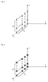
- Fig. 3 is a diagram of a massive planar single-polarized antenna array according to an embodiment of the present disclosure, and Fig.
- FIG. 3 shows a single-polarized antenna array with a dimension of N v ⁇ N h , wherein the product of the antenna element number N v in a vertical direction and the antenna element number N h in a horizontal direction is equal to the antenna number N of a sending side.
- Fig. 4 is a diagram of a massive planar dual-polarized antenna array according to an embodiment of the present disclosure, and Fig. 4 shows a dual-polarized antenna array with a dimension of N v ⁇ N h , wherein twice of the product of the antenna element number N v in a vertical direction and the antenna element number N h in a horizontal direction is equal to the antenna number N of a sending side.
- an antenna consists of at least one antenna array element with the same polarization direction, and the antenna may be equivalent to an antenna port in a Long Term Evolution (LTE) standard, wherein the antenna array element is a minimum component constituting the antenna.
- LTE Long Term Evolution
- channel information is a numerical indicator of a small-scale channel or a fast fading channel between a sending antenna and a receiving antenna.
- Fig. 5 is a diagram of antenna indexes of a planar single-polarized antenna array according to an embodiment of the present disclosure. As shown in Fig. 5 , antennae in the first row are indexed at first, sequentially being 1, 2, ..., n from right to left; then antennae in the second row are indexed, sequentially being n+1, n+2, ..., 2n from right to left, and so on, and the indexing is performed by row.
- Fig. 6 is a diagram of antenna indexes of a planar dual-polarized antenna array according to an embodiment of the present disclosure. As shown in Fig.
- antennae with a first polarization direction in the first row are indexed at first, sequentially being 1, 2, ..., n from right to left; then antennae with a second polarization direction in the first row are indexed, sequentially being n+1, n+2, ..., 2n from right to left; antennae with the first polarization direction in the second row are indexed next, sequentially being 2n+1, 2n+2, ..., 3n from right to left; antennae with the second polarization direction in the second row are indexed later on, sequentially being 3n+1, 3n+2, ..., 4n from right to left, and so on, and the indexing is performed by row by polarization.
- An embodiment of the present disclosure provides a method for acquiring channel information, which includes the following four steps.
- Step 1 indexes L of M antennae which send reference signals in N antennae are acquired, wherein N is the number of antennae of a sending side, and M is less than or equal to N.
- Step 2 channel information Y between the M antennae and a receiving antenna is acquired.
- Step 3 a unitary matrix W with a dimension of NxN is acquired.
- the information from the sending side is included in system or control information proprietary to a cell or a terminal, and includes, but not limited to, an antenna element number N v in a vertical direction, an antenna element number N h in a horizontal direction, a polarized antenna element indicator and related information about a polarized matrix W pol .
- W pol is a scalar "1"; and for a dual-polarized antenna element, W pol is a polarized matrix with a dimension of 2x2. Note: for a single-polarized antenna element, it is met that the product of N v and N h is N; and for a dual-polarized antenna element, it is met that twice of the product of N v and N h is N.
- Step 4 an estimate S' of channel information S between the N antennae and the receiving antenna is acquired according to the indexes L of the M antennae, the channel information Y between the M antennae and the receiving antenna and the unitary matrix W with the dimension of N ⁇ N.
- ⁇ represents the operation of calculating a norm of a vector
- s.t is a constraint condition mark
- H represents the operation of calculating the conjugate transpose of a matrix
- min(x) represents calculation of a variable value by which a value of X is minimized
- the sending side refers to a network side
- the receiving side refers to a terminal side.
- Fig. 8 is a diagram of antenna indexes of a single-polarized antenna array with a dimension of 8x8 according to an embodiment of the present disclosure. As shown in Fig. 8 , it is supposed that the number M of antennae which send reference signals is 10 ( ⁇ 64).
- a terminal side uses one receiving antenna.
- reference data of each antenna in the 10 antennae is a random sequence which is proprietary to the antenna and has an element modulus value of "1"
- the number of reference signal resource locations of each antenna is equal to the length of the reference data (or the random sequence)
- different antennae in the 10 antennae use the same or different reference signal resource locations, and for different antennae using the same reference signal resource locations, their reference data (random sequences) is orthogonal or approximately orthogonal, wherein the reference data is data which is sent at the reference signal resource locations and is known to a sender and a receiver, and the reference signal resource locations are time and/or frequency resource locations where the reference signals are sent.
- the terminal side acquires a random matrix P with a dimension of 10 ⁇ 64, wherein the 7th element in the 1th row of the random matrix P is "1", and other elements are 0"; the 15th element in the 2nd row is “1", and other elements are 0"; the 19th element in the 3rd row is “1", and other elements are 0"; the 28th element in the 4th row is "1", and other elements are 0", and so on, the 55th elements in the 10th row is "1", and other elements are 0".
- ⁇ represents operation of calculating a norm of a vector
- s.t is a constraint condition mark
- H represents operation of calculating the conjugate transpose of a matrix
- min(x) represents calculation of a variable value by which a value of X is minimized.
- Fig. 9 is a diagram of antenna indexes of a dual-polarized antenna array with a dimension of 8x8 according to an embodiment of the present disclosure. As shown in Fig. 9 , it is supposed that the number M of antennae which send reference signals is 20 ( ⁇ 128).
- a terminal side uses one receiving antenna.
- reference data of each antenna in the 20 antennae is a random sequence which is proprietary to the antenna and has an element modulus value of "1"
- the number of reference signal resource locations of each antenna is equal to the length of the reference data (or the random sequence)
- different antennae in the 20 antennae use the same or different reference signal resource locations, and for different antennae using the same reference signal resource locations, their reference data (random sequences) is orthogonal or approximately orthogonal, wherein the reference data is data which is sent at the reference signal resource locations and is known to a sender and a receiver, and the reference signal resource locations are time and/or frequency resource locations where the reference signals are sent.
- the terminal side acquires a random matrix P with a dimension of 20x128, wherein the 7th element in the 1st row of the random matrix P is "1", and other elements are 0"; the 17th element in the 2nd row is “1", and other elements are 0"; the 24th element in the 3rd row is “1", and other elements are 0"; the 32nd element in the 4th row is "1", and other elements are 0"; and following the same rule, the 126th elements in the 20th row is "1", and other elements are 0".
- ⁇ represents operation of calculating a norm of a vector
- s.t is a constraint condition mark
- H represents operation of calculating the conjugate transpose of a matrix
- min(x) represents calculation of a variable value by which a value of X is minimized.
- An embodiment of the present disclosure further provides a computer-readable storage medium, which includes a set of computer-executable instructions, the instructions being configured to execute the method for acquiring channel information of the embodiment of the present disclosure.
- the embodiments of the present disclosure may be provided as a method, a system or a computer program product. Therefore, the present disclosure may adopt a form of pure hardware embodiment, pure software embodiment and combined software and hardware embodiment. Moreover, the present disclosure may adopt a form of computer program product implemented on one or more computer-available storage media (including, but not limited to, a disk memory, a Compact Disc Read-Only Memory (CD-ROM) and an optical memory) including computer-available program codes.
- CD-ROM Compact Disc Read-Only Memory
- each flow and/or block in the flowcharts and/or the block diagrams and combinations of the flows and/or blocks in the flowcharts and/or the block diagrams may be implemented by computer program instructions.
- These computer program instructions may be provided for a universal computer, a dedicated computer, an embedded processor or a processor of other programmable data processing equipment to generate a machine, so that a device for realizing a function specified in one flow or more flows in the flowcharts and/or one block or more blocks in the block diagrams is generated by the instructions executed through the computer or the processor of the other programmable data processing equipment.
- These computer program instructions may also be stored in a computer-readable memory capable of guiding the computer or other programmable data processing equipment to work in a specific manner, so that a product including an instruction device may be generated by the instructions stored in the computer-readable memory, the instruction device realizing the function specified in one flow or many flows in the flowcharts and/or one block or many blocks in the block diagrams.
- These computer program instructions may further be loaded onto a computer or other programmable data processing equipment, so that a series of operating steps are executed on the computer or other programmable data processing equipment to generate processing implemented by the computer, and steps for realizing the function specified in one flow or many flows in the flowcharts and/or one block or many blocks in the block diagrams are provided by the instructions executed on the computer or the other programmable data processing equipment.
Landscapes
- Engineering & Computer Science (AREA)
- Signal Processing (AREA)
- Computer Networks & Wireless Communication (AREA)
- Power Engineering (AREA)
- Physics & Mathematics (AREA)
- Mathematical Physics (AREA)
- Radio Transmission System (AREA)
- Mobile Radio Communication Systems (AREA)
- Variable-Direction Aerials And Aerial Arrays (AREA)
Applications Claiming Priority (2)
| Application Number | Priority Date | Filing Date | Title |
|---|---|---|---|
| CN201310309285.2A CN104333407B (zh) | 2013-07-22 | 2013-07-22 | 一种信道信息的获取方法及装置 |
| PCT/CN2014/077937 WO2014166454A1 (fr) | 2013-07-22 | 2014-05-20 | Procédé et dispositif permettant l'acquisition d'informations de canal |
Publications (3)
| Publication Number | Publication Date |
|---|---|
| EP3026823A1 true EP3026823A1 (fr) | 2016-06-01 |
| EP3026823A4 EP3026823A4 (fr) | 2016-06-08 |
| EP3026823B1 EP3026823B1 (fr) | 2019-10-09 |
Family
ID=51688966
Family Applications (1)
| Application Number | Title | Priority Date | Filing Date |
|---|---|---|---|
| EP14783089.7A Active EP3026823B1 (fr) | 2013-07-22 | 2014-05-20 | Procédé et dispositif permettant l'acquisition d'informations de canal |
Country Status (4)
| Country | Link |
|---|---|
| US (1) | US9647739B2 (fr) |
| EP (1) | EP3026823B1 (fr) |
| CN (1) | CN104333407B (fr) |
| WO (1) | WO2014166454A1 (fr) |
Cited By (1)
| Publication number | Priority date | Publication date | Assignee | Title |
|---|---|---|---|---|
| EP3306881A4 (fr) * | 2015-06-07 | 2019-02-13 | LG Electronics Inc. | Procédé de mesure de canal dans un système de communication sans fil et appareil correspondant |
Families Citing this family (7)
| Publication number | Priority date | Publication date | Assignee | Title |
|---|---|---|---|---|
| KR102175707B1 (ko) * | 2014-01-20 | 2020-11-06 | 한국전자통신연구원 | 3차원 안테나 어레이 장치 및 빔포밍 방법 |
| US10135508B2 (en) * | 2014-10-13 | 2018-11-20 | Electronics And Telecommunications Research Institute | Method and apparatus for generating common signal in multiple input multiple output system |
| CN106549883A (zh) * | 2015-09-17 | 2017-03-29 | 清华大学 | 适于大规模多天线系统的下行训练方法及系统 |
| CN107294880B (zh) * | 2016-03-31 | 2020-07-31 | 上海诺基亚贝尔股份有限公司 | 用于确定信道信息的方法和设备 |
| CN109802801B (zh) | 2017-11-17 | 2021-12-14 | 华为技术有限公司 | 发送和接收信号的方法、装置和系统 |
| CN109842580B (zh) * | 2017-11-28 | 2021-02-12 | 华为技术有限公司 | 一种信道估计方法以及相关设备 |
| CN109412665B (zh) * | 2018-07-09 | 2022-03-22 | 展讯通信(上海)有限公司 | 信道状态的指示及获取方法、发送设备、接收设备、介质 |
Family Cites Families (9)
| Publication number | Priority date | Publication date | Assignee | Title |
|---|---|---|---|---|
| CN1917397B (zh) * | 2006-09-19 | 2012-09-05 | 北京邮电大学 | 一种mimo-ofdm系统信道估计的方法 |
| US8086242B2 (en) | 2007-03-21 | 2011-12-27 | Broadcom Corporation | Method and system for adaptive allocation of feedback resources for CQI and transmit pre-coding |
| CN101577968B (zh) * | 2008-05-05 | 2011-08-03 | 华为技术有限公司 | 一种获取下行信道信息的方法、系统和装置 |
| KR101755038B1 (ko) * | 2009-01-30 | 2017-07-06 | 엘지전자 주식회사 | 무선 통신 시스템에서 참조신호 전송 장치 및 방법 |
| CN101808064A (zh) * | 2009-02-13 | 2010-08-18 | 华为技术有限公司 | 一种无线接收系统以及信道估计处理方法、装置 |
| CN102412881B (zh) * | 2010-09-26 | 2015-06-17 | 日电(中国)有限公司 | 无线通信系统和用于无线通信系统的波束形成训练方法 |
| US8837621B2 (en) | 2011-05-09 | 2014-09-16 | Telefonaktiebolaget L M Ericsson (Publ) | Channel estimation for a very large-scale multiple-input multiple output (MIMO) system |
| US9178590B2 (en) * | 2011-12-27 | 2015-11-03 | Industrial Technology Research Institute | Channel information feedback method and wireless communication device using the same |
| KR20150035545A (ko) * | 2012-06-24 | 2015-04-06 | 엘지전자 주식회사 | 무선 통신 시스템에서 채널 상태 정보 보고 방법 및 장치 |
-
2013
- 2013-07-22 CN CN201310309285.2A patent/CN104333407B/zh not_active Expired - Fee Related
-
2014
- 2014-05-20 EP EP14783089.7A patent/EP3026823B1/fr active Active
- 2014-05-20 WO PCT/CN2014/077937 patent/WO2014166454A1/fr active Application Filing
- 2014-05-20 US US14/906,010 patent/US9647739B2/en active Active
Cited By (2)
| Publication number | Priority date | Publication date | Assignee | Title |
|---|---|---|---|---|
| EP3306881A4 (fr) * | 2015-06-07 | 2019-02-13 | LG Electronics Inc. | Procédé de mesure de canal dans un système de communication sans fil et appareil correspondant |
| US10574486B2 (en) | 2015-06-07 | 2020-02-25 | Lg Electronics Inc. | Channel measurement method in wireless communication system and apparatus therefor |
Also Published As
| Publication number | Publication date |
|---|---|
| CN104333407B (zh) | 2019-02-01 |
| EP3026823A4 (fr) | 2016-06-08 |
| EP3026823B1 (fr) | 2019-10-09 |
| WO2014166454A1 (fr) | 2014-10-16 |
| US9647739B2 (en) | 2017-05-09 |
| CN104333407A (zh) | 2015-02-04 |
| US20160156399A1 (en) | 2016-06-02 |
Similar Documents
| Publication | Publication Date | Title |
|---|---|---|
| EP3026823B1 (fr) | Procédé et dispositif permettant l'acquisition d'informations de canal | |
| EP3035556B1 (fr) | Procédé et appareil de transmission de signal commun dans une formation de faisceau hybride | |
| US9882615B2 (en) | Method, system, and device for transmitting coding instruction information and for determining pre-coding matrix | |
| US20150333884A1 (en) | Beam Forming Using a Two-Dimensional Antenna Arrangement | |
| EP2911330B1 (fr) | Procédé, système et dispositif pour transmettre des informations d'instruction de codage et pour déterminer une matrice de précodage | |
| EP2410663A1 (fr) | Procédé, appareil et système de distribution de puissance de liaison descendante | |
| CN105210405A (zh) | 报告信道状态信息的方法、用户设备和基站 | |
| US12089064B2 (en) | Beamforming method and apparatus, radio access network device, and readable storage medium | |
| US11082275B2 (en) | Electrical apparatus and wireless communication method for communication device with multiple antennas | |
| US9954695B2 (en) | Channel measurement method for large-scale antennas, and user terminal | |
| CN103858359B (zh) | 一种天线阵列、信号映射的方法及基站 | |
| CN104660311A (zh) | 一种波束赋形方法、确定初始波束索引集合的方法及装置 | |
| CN113922848A (zh) | 信号发送方法、信道估计方法、发送端设备及接收端设备 | |
| CN103795450A (zh) | 传输编码指示信息和确定预编码矩阵的方法、系统及设备 | |
| CN103795489A (zh) | 传输编码指示信息和确定预编码矩阵的方法、系统及设备 | |
| EP4178294A1 (fr) | Procédé et appareil d'apprentissage de faisceau | |
| WO2016201984A1 (fr) | Procédé de transmission de données, et station de base | |
| CN105337907B (zh) | 一种获取信道状态信息的方法和装置 | |
| CN102148779B (zh) | 一种信号检测的方法及装置 | |
| KR20200022307A (ko) | 단일 차원 최대 우도 심볼 검출을 위한 장치들, 컴퓨터로 독출 가능한 매체 및 방법들 | |
| CN104113496A (zh) | 一种利用序贯导频序列进行信道估计的方法 | |
| CN106161290B (zh) | 一种流间干扰计算方法、装置及通信系统 | |
| WO2015067031A1 (fr) | Procédé et dispositif d'acquisition d'informations de canal | |
| CN102723976B (zh) | 一种波束赋形方法及装置 | |
| CN103873127A (zh) | 一种自适应波束成形中快速生成阻塞矩阵的方法 |
Legal Events
| Date | Code | Title | Description |
|---|---|---|---|
| PUAI | Public reference made under article 153(3) epc to a published international application that has entered the european phase |
Free format text: ORIGINAL CODE: 0009012 |
|
| 17P | Request for examination filed |
Effective date: 20160127 |
|
| AK | Designated contracting states |
Kind code of ref document: A1 Designated state(s): AL AT BE BG CH CY CZ DE DK EE ES FI FR GB GR HR HU IE IS IT LI LT LU LV MC MK MT NL NO PL PT RO RS SE SI SK SM TR |
|
| AX | Request for extension of the european patent |
Extension state: BA ME |
|
| A4 | Supplementary search report drawn up and despatched |
Effective date: 20160511 |
|
| RIC1 | Information provided on ipc code assigned before grant |
Ipc: H04L 25/02 20060101ALI20160504BHEP Ipc: H04B 7/04 20060101ALI20160504BHEP Ipc: H04L 5/00 20060101ALI20160504BHEP Ipc: H04B 7/10 20060101AFI20160504BHEP Ipc: H04B 7/06 20060101ALI20160504BHEP |
|
| DAX | Request for extension of the european patent (deleted) | ||
| STAA | Information on the status of an ep patent application or granted ep patent |
Free format text: STATUS: EXAMINATION IS IN PROGRESS |
|
| 17Q | First examination report despatched |
Effective date: 20170710 |
|
| GRAP | Despatch of communication of intention to grant a patent |
Free format text: ORIGINAL CODE: EPIDOSNIGR1 |
|
| STAA | Information on the status of an ep patent application or granted ep patent |
Free format text: STATUS: GRANT OF PATENT IS INTENDED |
|
| INTG | Intention to grant announced |
Effective date: 20190424 |
|
| GRAS | Grant fee paid |
Free format text: ORIGINAL CODE: EPIDOSNIGR3 |
|
| GRAA | (expected) grant |
Free format text: ORIGINAL CODE: 0009210 |
|
| STAA | Information on the status of an ep patent application or granted ep patent |
Free format text: STATUS: THE PATENT HAS BEEN GRANTED |
|
| AK | Designated contracting states |
Kind code of ref document: B1 Designated state(s): AL AT BE BG CH CY CZ DE DK EE ES FI FR GB GR HR HU IE IS IT LI LT LU LV MC MK MT NL NO PL PT RO RS SE SI SK SM TR |
|
| REG | Reference to a national code |
Ref country code: GB Ref legal event code: FG4D |
|
| REG | Reference to a national code |
Ref country code: CH Ref legal event code: EP |
|
| REG | Reference to a national code |
Ref country code: IE Ref legal event code: FG4D |
|
| REG | Reference to a national code |
Ref country code: DE Ref legal event code: R096 Ref document number: 602014054957 Country of ref document: DE |
|
| REG | Reference to a national code |
Ref country code: AT Ref legal event code: REF Ref document number: 1190032 Country of ref document: AT Kind code of ref document: T Effective date: 20191115 |
|
| REG | Reference to a national code |
Ref country code: NL Ref legal event code: MP Effective date: 20191009 |
|
| REG | Reference to a national code |
Ref country code: LT Ref legal event code: MG4D |
|
| REG | Reference to a national code |
Ref country code: AT Ref legal event code: MK05 Ref document number: 1190032 Country of ref document: AT Kind code of ref document: T Effective date: 20191009 |
|
| PG25 | Lapsed in a contracting state [announced via postgrant information from national office to epo] |
Ref country code: PT Free format text: LAPSE BECAUSE OF FAILURE TO SUBMIT A TRANSLATION OF THE DESCRIPTION OR TO PAY THE FEE WITHIN THE PRESCRIBED TIME-LIMIT Effective date: 20200210 Ref country code: NL Free format text: LAPSE BECAUSE OF FAILURE TO SUBMIT A TRANSLATION OF THE DESCRIPTION OR TO PAY THE FEE WITHIN THE PRESCRIBED TIME-LIMIT Effective date: 20191009 Ref country code: ES Free format text: LAPSE BECAUSE OF FAILURE TO SUBMIT A TRANSLATION OF THE DESCRIPTION OR TO PAY THE FEE WITHIN THE PRESCRIBED TIME-LIMIT Effective date: 20191009 Ref country code: LT Free format text: LAPSE BECAUSE OF FAILURE TO SUBMIT A TRANSLATION OF THE DESCRIPTION OR TO PAY THE FEE WITHIN THE PRESCRIBED TIME-LIMIT Effective date: 20191009 Ref country code: PL Free format text: LAPSE BECAUSE OF FAILURE TO SUBMIT A TRANSLATION OF THE DESCRIPTION OR TO PAY THE FEE WITHIN THE PRESCRIBED TIME-LIMIT Effective date: 20191009 Ref country code: NO Free format text: LAPSE BECAUSE OF FAILURE TO SUBMIT A TRANSLATION OF THE DESCRIPTION OR TO PAY THE FEE WITHIN THE PRESCRIBED TIME-LIMIT Effective date: 20200109 Ref country code: SE Free format text: LAPSE BECAUSE OF FAILURE TO SUBMIT A TRANSLATION OF THE DESCRIPTION OR TO PAY THE FEE WITHIN THE PRESCRIBED TIME-LIMIT Effective date: 20191009 Ref country code: LV Free format text: LAPSE BECAUSE OF FAILURE TO SUBMIT A TRANSLATION OF THE DESCRIPTION OR TO PAY THE FEE WITHIN THE PRESCRIBED TIME-LIMIT Effective date: 20191009 Ref country code: AT Free format text: LAPSE BECAUSE OF FAILURE TO SUBMIT A TRANSLATION OF THE DESCRIPTION OR TO PAY THE FEE WITHIN THE PRESCRIBED TIME-LIMIT Effective date: 20191009 Ref country code: BG Free format text: LAPSE BECAUSE OF FAILURE TO SUBMIT A TRANSLATION OF THE DESCRIPTION OR TO PAY THE FEE WITHIN THE PRESCRIBED TIME-LIMIT Effective date: 20200109 Ref country code: FI Free format text: LAPSE BECAUSE OF FAILURE TO SUBMIT A TRANSLATION OF THE DESCRIPTION OR TO PAY THE FEE WITHIN THE PRESCRIBED TIME-LIMIT Effective date: 20191009 Ref country code: GR Free format text: LAPSE BECAUSE OF FAILURE TO SUBMIT A TRANSLATION OF THE DESCRIPTION OR TO PAY THE FEE WITHIN THE PRESCRIBED TIME-LIMIT Effective date: 20200110 |
|
| PG25 | Lapsed in a contracting state [announced via postgrant information from national office to epo] |
Ref country code: RS Free format text: LAPSE BECAUSE OF FAILURE TO SUBMIT A TRANSLATION OF THE DESCRIPTION OR TO PAY THE FEE WITHIN THE PRESCRIBED TIME-LIMIT Effective date: 20191009 Ref country code: IS Free format text: LAPSE BECAUSE OF FAILURE TO SUBMIT A TRANSLATION OF THE DESCRIPTION OR TO PAY THE FEE WITHIN THE PRESCRIBED TIME-LIMIT Effective date: 20200224 Ref country code: HR Free format text: LAPSE BECAUSE OF FAILURE TO SUBMIT A TRANSLATION OF THE DESCRIPTION OR TO PAY THE FEE WITHIN THE PRESCRIBED TIME-LIMIT Effective date: 20191009 |
|
| PG25 | Lapsed in a contracting state [announced via postgrant information from national office to epo] |
Ref country code: AL Free format text: LAPSE BECAUSE OF FAILURE TO SUBMIT A TRANSLATION OF THE DESCRIPTION OR TO PAY THE FEE WITHIN THE PRESCRIBED TIME-LIMIT Effective date: 20191009 |
|
| REG | Reference to a national code |
Ref country code: DE Ref legal event code: R097 Ref document number: 602014054957 Country of ref document: DE |
|
| PG2D | Information on lapse in contracting state deleted |
Ref country code: IS |
|
| PG25 | Lapsed in a contracting state [announced via postgrant information from national office to epo] |
Ref country code: EE Free format text: LAPSE BECAUSE OF FAILURE TO SUBMIT A TRANSLATION OF THE DESCRIPTION OR TO PAY THE FEE WITHIN THE PRESCRIBED TIME-LIMIT Effective date: 20191009 Ref country code: DK Free format text: LAPSE BECAUSE OF FAILURE TO SUBMIT A TRANSLATION OF THE DESCRIPTION OR TO PAY THE FEE WITHIN THE PRESCRIBED TIME-LIMIT Effective date: 20191009 Ref country code: RO Free format text: LAPSE BECAUSE OF FAILURE TO SUBMIT A TRANSLATION OF THE DESCRIPTION OR TO PAY THE FEE WITHIN THE PRESCRIBED TIME-LIMIT Effective date: 20191009 Ref country code: CZ Free format text: LAPSE BECAUSE OF FAILURE TO SUBMIT A TRANSLATION OF THE DESCRIPTION OR TO PAY THE FEE WITHIN THE PRESCRIBED TIME-LIMIT Effective date: 20191009 Ref country code: IS Free format text: LAPSE BECAUSE OF FAILURE TO SUBMIT A TRANSLATION OF THE DESCRIPTION OR TO PAY THE FEE WITHIN THE PRESCRIBED TIME-LIMIT Effective date: 20200209 |
|
| PLBE | No opposition filed within time limit |
Free format text: ORIGINAL CODE: 0009261 |
|
| STAA | Information on the status of an ep patent application or granted ep patent |
Free format text: STATUS: NO OPPOSITION FILED WITHIN TIME LIMIT |
|
| PG25 | Lapsed in a contracting state [announced via postgrant information from national office to epo] |
Ref country code: SM Free format text: LAPSE BECAUSE OF FAILURE TO SUBMIT A TRANSLATION OF THE DESCRIPTION OR TO PAY THE FEE WITHIN THE PRESCRIBED TIME-LIMIT Effective date: 20191009 Ref country code: IT Free format text: LAPSE BECAUSE OF FAILURE TO SUBMIT A TRANSLATION OF THE DESCRIPTION OR TO PAY THE FEE WITHIN THE PRESCRIBED TIME-LIMIT Effective date: 20191009 Ref country code: SK Free format text: LAPSE BECAUSE OF FAILURE TO SUBMIT A TRANSLATION OF THE DESCRIPTION OR TO PAY THE FEE WITHIN THE PRESCRIBED TIME-LIMIT Effective date: 20191009 |
|
| 26N | No opposition filed |
Effective date: 20200710 |
|
| PG25 | Lapsed in a contracting state [announced via postgrant information from national office to epo] |
Ref country code: SI Free format text: LAPSE BECAUSE OF FAILURE TO SUBMIT A TRANSLATION OF THE DESCRIPTION OR TO PAY THE FEE WITHIN THE PRESCRIBED TIME-LIMIT Effective date: 20191009 |
|
| REG | Reference to a national code |
Ref country code: DE Ref legal event code: R119 Ref document number: 602014054957 Country of ref document: DE |
|
| PG25 | Lapsed in a contracting state [announced via postgrant information from national office to epo] |
Ref country code: MC Free format text: LAPSE BECAUSE OF FAILURE TO SUBMIT A TRANSLATION OF THE DESCRIPTION OR TO PAY THE FEE WITHIN THE PRESCRIBED TIME-LIMIT Effective date: 20191009 Ref country code: CH Free format text: LAPSE BECAUSE OF NON-PAYMENT OF DUE FEES Effective date: 20200531 Ref country code: LI Free format text: LAPSE BECAUSE OF NON-PAYMENT OF DUE FEES Effective date: 20200531 |
|
| REG | Reference to a national code |
Ref country code: BE Ref legal event code: MM Effective date: 20200531 |
|
| PG25 | Lapsed in a contracting state [announced via postgrant information from national office to epo] |
Ref country code: LU Free format text: LAPSE BECAUSE OF NON-PAYMENT OF DUE FEES Effective date: 20200520 |
|
| PG25 | Lapsed in a contracting state [announced via postgrant information from national office to epo] |
Ref country code: IE Free format text: LAPSE BECAUSE OF NON-PAYMENT OF DUE FEES Effective date: 20200520 |
|
| PG25 | Lapsed in a contracting state [announced via postgrant information from national office to epo] |
Ref country code: BE Free format text: LAPSE BECAUSE OF NON-PAYMENT OF DUE FEES Effective date: 20200531 Ref country code: DE Free format text: LAPSE BECAUSE OF NON-PAYMENT OF DUE FEES Effective date: 20201201 |
|
| PG25 | Lapsed in a contracting state [announced via postgrant information from national office to epo] |
Ref country code: TR Free format text: LAPSE BECAUSE OF FAILURE TO SUBMIT A TRANSLATION OF THE DESCRIPTION OR TO PAY THE FEE WITHIN THE PRESCRIBED TIME-LIMIT Effective date: 20191009 Ref country code: MT Free format text: LAPSE BECAUSE OF FAILURE TO SUBMIT A TRANSLATION OF THE DESCRIPTION OR TO PAY THE FEE WITHIN THE PRESCRIBED TIME-LIMIT Effective date: 20191009 Ref country code: CY Free format text: LAPSE BECAUSE OF FAILURE TO SUBMIT A TRANSLATION OF THE DESCRIPTION OR TO PAY THE FEE WITHIN THE PRESCRIBED TIME-LIMIT Effective date: 20191009 |
|
| PG25 | Lapsed in a contracting state [announced via postgrant information from national office to epo] |
Ref country code: MK Free format text: LAPSE BECAUSE OF FAILURE TO SUBMIT A TRANSLATION OF THE DESCRIPTION OR TO PAY THE FEE WITHIN THE PRESCRIBED TIME-LIMIT Effective date: 20191009 |
|
| REG | Reference to a national code |
Ref country code: FR Ref legal event code: PLFP Year of fee payment: 10 |
|
| REG | Reference to a national code |
Ref country code: GB Ref legal event code: 732E Free format text: REGISTERED BETWEEN 20230622 AND 20230628 |
|
| PGFP | Annual fee paid to national office [announced via postgrant information from national office to epo] |
Ref country code: GB Payment date: 20240521 Year of fee payment: 11 |
|
| PGFP | Annual fee paid to national office [announced via postgrant information from national office to epo] |
Ref country code: FR Payment date: 20240523 Year of fee payment: 11 |