KR101755038B1 - Apparatus and method of transmitting reference signal in wireless communication system - Google Patents
Apparatus and method of transmitting reference signal in wireless communication system Download PDFInfo
- Publication number
- KR101755038B1 KR101755038B1 KR1020100008124A KR20100008124A KR101755038B1 KR 101755038 B1 KR101755038 B1 KR 101755038B1 KR 1020100008124 A KR1020100008124 A KR 1020100008124A KR 20100008124 A KR20100008124 A KR 20100008124A KR 101755038 B1 KR101755038 B1 KR 101755038B1
- Authority
- KR
- South Korea
- Prior art keywords
- reference signal
- antenna
- antennas
- virtual antenna
- signal sequence
- Prior art date
Links
Images


Classifications
-
- H—ELECTRICITY
- H04—ELECTRIC COMMUNICATION TECHNIQUE
- H04L—TRANSMISSION OF DIGITAL INFORMATION, e.g. TELEGRAPHIC COMMUNICATION
- H04L5/00—Arrangements affording multiple use of the transmission path
- H04L5/003—Arrangements for allocating sub-channels of the transmission path
- H04L5/0048—Allocation of pilot signals, i.e. of signals known to the receiver
-
- H—ELECTRICITY
- H04—ELECTRIC COMMUNICATION TECHNIQUE
- H04B—TRANSMISSION
- H04B7/00—Radio transmission systems, i.e. using radiation field
- H04B7/02—Diversity systems; Multi-antenna system, i.e. transmission or reception using multiple antennas
- H04B7/04—Diversity systems; Multi-antenna system, i.e. transmission or reception using multiple antennas using two or more spaced independent antennas
- H04B7/06—Diversity systems; Multi-antenna system, i.e. transmission or reception using multiple antennas using two or more spaced independent antennas at the transmitting station
- H04B7/0613—Diversity systems; Multi-antenna system, i.e. transmission or reception using multiple antennas using two or more spaced independent antennas at the transmitting station using simultaneous transmission
- H04B7/0615—Diversity systems; Multi-antenna system, i.e. transmission or reception using multiple antennas using two or more spaced independent antennas at the transmitting station using simultaneous transmission of weighted versions of same signal
- H04B7/0617—Diversity systems; Multi-antenna system, i.e. transmission or reception using multiple antennas using two or more spaced independent antennas at the transmitting station using simultaneous transmission of weighted versions of same signal for beam forming
-
- H—ELECTRICITY
- H04—ELECTRIC COMMUNICATION TECHNIQUE
- H04B—TRANSMISSION
- H04B7/00—Radio transmission systems, i.e. using radiation field
- H04B7/02—Diversity systems; Multi-antenna system, i.e. transmission or reception using multiple antennas
- H04B7/04—Diversity systems; Multi-antenna system, i.e. transmission or reception using multiple antennas using two or more spaced independent antennas
- H04B7/06—Diversity systems; Multi-antenna system, i.e. transmission or reception using multiple antennas using two or more spaced independent antennas at the transmitting station
- H04B7/0613—Diversity systems; Multi-antenna system, i.e. transmission or reception using multiple antennas using two or more spaced independent antennas at the transmitting station using simultaneous transmission
- H04B7/0684—Diversity systems; Multi-antenna system, i.e. transmission or reception using multiple antennas using two or more spaced independent antennas at the transmitting station using simultaneous transmission using different training sequences per antenna
Abstract
무선 통신 시스템에서 참조신호 전송 장치 및 방법을 제공한다. 상기 장치는 N개의 안테나 및 상기 N개의 안테나와 연결되어, 각각의 K개의 참조신호 시퀀스 및 각각의 K개의 가상 안테나 벡터를 기반으로 각각의 K개의 참조신호 시퀀스 벡터를 생성하고(K<N), 상기 각각의 K개의 참조신호 시퀀스 벡터를 상기 N개의 안테나를 통해 전송하도록 형성되는 프로세서를 포함한다. An apparatus and method for transmitting a reference signal in a wireless communication system are provided. The apparatus is coupled to the N antennas and the N antennas to generate K reference signal sequence vectors (K < N) based on each of the K reference signal sequences and each of the K virtual antenna vectors, And a processor configured to transmit the K reference signal sequence vectors through the N antennas.
Description
본 발명은 무선 통신에 관한 것으로, 더욱 상세하게는 무선 통신 시스템에서 참조신호 전송 장치 및 방법에 관한 것이다. BACKGROUND OF THE
무선 통신 시스템은 음성이나 데이터 등과 같은 다양한 종류의 통신 서비스를 제공하기 위해 광범위하게 전개되고 있다. 무선 통신 시스템의 목적은 다수의 사용자가 위치와 이동성에 관계없이 신뢰할 수 있는(reliable) 통신을 할 수 있도록 하는 것이다. 그런데 무선 채널(wireless channel)은 경로 손실(path loss), 잡음(noise), 다중 경로(multipath)에 의한 페이딩(fading) 현상, 심벌간 간섭(ISI, intersymbol interference) 또는 단말의 이동성으로 인한 도플러 효과(Doppler effect) 등의 비이상적인 특성이 있다. 따라서 무선 채널의 비이상적 특성을 극복하고, 무선 통신의 신뢰도(reliability)를 높이기 위해 다양한 기술이 개발되고 있다. Background of the Invention [0002] Wireless communication systems are widely deployed to provide various types of communication services such as voice and data. The purpose of a wireless communication system is to allow multiple users to communicate reliably regardless of location and mobility. However, a wireless channel is a wireless channel that is affected by path loss, noise, fading due to multipath, intersymbol interference (ISI) (Doppler effect). Accordingly, various technologies have been developed to overcome the non-ideal characteristics of the wireless channel and to increase the reliability of the wireless communication.
신뢰할 수 있는 고속의 데이터 서비스를 지원하기 위한 기술로 MIMO(multiple input multiple output)가 있다. MIMO 기법은 다중 전송 안테나와 다중 수신 안테나를 사용하여 데이터의 송수신 효율을 향상시킨다. MIMO 기법에는 공간 다중화(spatial multiplexing), 전송 다이버시티(transmit diversity), 빔포밍(beamforming) 등이 있다. There is multiple input multiple output (MIMO) as a technique to support reliable high-speed data service. The MIMO scheme improves the transmission and reception efficiency of data by using multiple transmit antennas and multiple receive antennas. MIMO schemes include spatial multiplexing, transmit diversity, and beamforming.
다중 수신 안테나 및 다중 전송 안테나에 의해 MIMO 채널 행렬이 형성된다. MIMO 채널 행렬로부터 랭크(rank)를 구할 수 있다. 랭크는 공간 레이어(spatial layer)의 개수이다. 랭크는 전송기가 동시에 전송할 수 있는 공간 스트림(spatial stream)의 개수라고 정의될 수도 있다. 랭크는 공간 다중화율이라고도 한다. 전송 안테나 개수를 Nt, 수신 안테나의 개수를 Nr이라 할 때, 랭크 R은 R ≤ min{Nt, Nr}이 된다. A MIMO channel matrix is formed by multiple receive antennas and multiple transmit antennas. A rank can be obtained from the MIMO channel matrix. The rank is the number of spatial layers. The rank may be defined as the number of spatial streams that a transmitter can simultaneously transmit. The rank is also called the spatial multiplexing rate. When the number of transmission antennas is Nt and the number of reception antennas is Nr, the rank R becomes R? Min {Nt, Nr}.
무선 통신 시스템에서는 채널 측정(channel measurement), 정보 복조(demodulation) 등을 위하여 전송기와 수신기가 모두 알고 있는 신호가 필요하다. 전송기와 수신기가 모두 알고 있는 신호를 참조신호(reference signal, RS)라 한다. 참조신호는 파일럿(pilot)으로도 불릴 수 있다. In a wireless communication system, a signal known to both a transmitter and a receiver is required for channel measurement, information demodulation, and the like. A signal known to both the transmitter and the receiver is referred to as a reference signal (RS). The reference signal may also be referred to as a pilot.
수신기는 참조신호를 통해 전송기와 수신기 사이의 채널을 추정하고, 추정된 채널을 이용하여 정보를 복조할 수 있다. 단말이 기지국으로부터 전송된 참조신호를 수신한 경우, 단말은 참조신호를 통해 채널을 측정하고, 기지국으로 채널 상태 정보를 피드백할 수 있다. 전송기로부터 전송된 신호는 전송 안테나마다 또는 공간 레이어마다 대응되는 채널을 겪기 때문에, 참조신호는 각 전송 안테나별 또는 공간 레이어별로 전송될 수 있다. The receiver can estimate the channel between the transmitter and the receiver through the reference signal and demodulate the information using the estimated channel. When a terminal receives a reference signal transmitted from a base station, the terminal measures a channel through a reference signal and can feedback channel state information to the base station. Since a signal transmitted from a transmitter undergoes a channel corresponding to each transmit antenna or each spatial layer, a reference signal can be transmitted for each transmit antenna or for each spatial layer.
한편, ITU(International Telecommunication Union)에서는 3세대 이후의 차세대 이동 통신 시스템으로 IMT-A(International Mobile Telecommunication-Advanced) 시스템의 표준화를 진행하고 있다. IMT-A 시스템의 목표는 하향링크 1Gbps(gigabits per second) 및 상향링크 500Mbps(megabits per second)인 고속의 전송률(transmission rate)을 제공하고, IP(internet protocol) 기반의 멀티미디어 심리스(seamless) 서비스를 지원하는 것이다. 3GPP(3rd Generation Partnership Project)에서는 IMT-A 시스템을 위한 후보 기술로 LTE-A(Long Term Evolution-Advanced) 시스템을 고려하고 있다. Meanwhile, the International Telecommunication Union (ITU) is proceeding with the standardization of the International Mobile Telecommunication-Advanced (IMT-A) system as a next generation mobile communication system after the third generation. The goal of the IMT-A system is to provide a high-speed transmission rate of 1 Gbps (downlink) gigabits per second (Gbps) and 500 Mbps (uplink) and provide seamless multimedia services based on IP (Internet Protocol) Support. The 3rd Generation Partnership Project (3GPP) considers Long Term Evolution-Advanced (LTE-A) system as a candidate technology for the IMT-A system.
LTE 시스템은 하향링크 전송은 최대 4개의 전송 안테나까지 지원되고, LTE-A 시스템은 하향링크 전송은 최대 8개의 전송 안테나까지 지원된다. 그런데 셀 내에는 LTE 시스템이 적용되는 단말(이하, LTE 단말)과 LTE-A 시스템이 적용되는 단말(이하, LTE-A 단말)이 공존(coexising)할 수 있다. 따라서 LTE-A 시스템은 LTE 단말 및 LTE-A 단말을 함께 지원할 수 있도록 설계되어야 한다. 그런데 서로 다른 개수의 안테나 전송이 지원되는 경우, 참조신호 전송 장치 및 방법이 문제된다. 따라서 무선 통신 시스템에서 효율적인 참조신호 전송 장치 및 방법을 제공할 필요가 있다.The LTE system supports up to 4 transmit antennas for downlink transmissions and up to 8 transmit antennas for downlink transmissions in the LTE-A system. However, a terminal (hereinafter referred to as an LTE terminal) to which an LTE system is applied and a terminal to which an LTE-A system is applied (hereinafter referred to as an LTE-A terminal) may coexist within the cell. Therefore, LTE-A system should be designed to support LTE terminal and LTE-A terminal together. However, when different numbers of antenna transmissions are supported, reference signal transmission apparatuses and methods are problematic. Therefore, there is a need to provide an efficient reference signal transmission apparatus and method in a wireless communication system.
본 발명이 이루고자 하는 기술적 과제는 무선 통신 시스템에서 참조신호 전송 장치 및 방법을 제공하는 데 있다.SUMMARY OF THE INVENTION It is an object of the present invention to provide an apparatus and method for transmitting a reference signal in a wireless communication system.
일 양태에서, 무선 통신 시스템에서 참조신호 전송 장치를 제공한다. 상기 장치는 N개의 안테나 및 상기 N개의 안테나와 연결되어, 각각의 K개의 참조신호 시퀀스 및 각각의 K개의 가상 안테나 벡터를 기반으로 각각의 K개의 참조신호 시퀀스 벡터를 생성하고(K<N), 상기 각각의 K개의 참조신호 시퀀스 벡터를 상기 N개의 안테나를 통해 전송하도록 형성되는 프로세서를 포함한다. In one aspect, a reference signal transmission apparatus is provided in a wireless communication system. The apparatus is coupled to the N antennas and the N antennas to generate K reference signal sequence vectors (K < N) based on each of the K reference signal sequences and each of the K virtual antenna vectors, And a processor configured to transmit the K reference signal sequence vectors through the N antennas.
다른 양태에서, 무선 통신 시스템에서 참조신호 전송 방법을 제공한다. 상기 방법은 각각의 K개의 참조신호 시퀀스 및 각각의 K개의 가상 안테나 벡터를 기반으로 각각의 K개의 참조신호 시퀀스 벡터를 생성하는 단계(K<N) 및 상기 각각의 K개의 참조신호 시퀀스 벡터를 N개의 안테나를 통해 전송하는 단계를 포함한다. In another aspect, a method of transmitting a reference signal in a wireless communication system is provided. The method includes generating (K < N) K reference signal sequence vectors for each K reference signal sequence and each K virtual antenna vector, and generating each of the K reference signal sequence vectors as N ≪ / RTI > antennas.
무선 통신 시스템에서 효율적인 참조신호 전송 장치 및 방법을 제공할 수 있다. 따라서 전체 시스템 성능이 향상될 수 있다. An efficient reference signal transmitting apparatus and method in a wireless communication system can be provided. Thus, overall system performance can be improved.
도 1은 무선 통신 시스템을 나타낸 블록도이다.
도 2는 무선 프레임(radio frame) 구조의 예를 나타낸다.
도 3은 하나의 하향링크 슬롯에 대한 자원 그리드(resource grid)를 나타낸 예시도이다.
도 4는 하향링크 서브프레임의 구조의 예를 나타낸다.
도 5는 노멀 CP의 경우, 하나의 안테나에 대한 공용 참조신호의 맵핑 예를 나타낸다.
도 6은 노멀 CP의 경우, 2개의 안테나에 대한 공용 참조신호들의 맵핑 예를 나타낸다.
도 7은 노멀 CP의 경우, 4개의 안테나에 대한 공용 참조신호들의 맵핑 예를 나타낸다.
도 8은 확장된 CP의 경우, 하나의 안테나에 대한 공용 참조신호의 맵핑 예를 나타낸다.
도 9는 확장된 CP의 경우, 2개의 안테나에 대한 공용 참조신호들의 맵핑 예를 나타낸다.
도 10은 확장된 CP의 경우, 4개의 안테나에 대한 공용 참조신호들의 맵핑 예를 나타낸다.
도 11은 LTE에서 노멀 CP의 경우, 전용 참조신호의 맵핑 예를 나타낸다.
도 12는 LTE에서 확장된 CP의 경우, 전용 참조신호의 맵핑 예를 나타낸다.
도 13은 안테나 가상화 기법을 사용하는 전송기 구조의 예를 나타낸 블록도이다.
도 14는 하나의 가상 안테나를 통해 참조신호가 전송되는 무선 통신 시스템의 예를 나타낸 블록도이다.
도 15는 본 발명의 실시예가 구현되는 무선 통신을 위한 장치를 나타낸 블록도이다. 1 is a block diagram illustrating a wireless communication system.
2 shows an example of a radio frame structure.
3 is an exemplary diagram illustrating a resource grid for one downlink slot.
4 shows an example of the structure of the downlink subframe.
5 shows an example of mapping of a common reference signal to one antenna in the case of a normal CP.
6 shows an example of mapping common reference signals for two antennas in case of a normal CP.
7 shows an example of mapping of common reference signals for four antennas in case of a normal CP.
8 shows an example of a mapping of a common reference signal to one antenna in the case of an extended CP.
9 shows an example of mapping of common reference signals for two antennas in the case of an extended CP.
10 shows an example of a mapping of common reference signals for four antennas in case of an extended CP.
11 shows an example of mapping of a dedicated reference signal in case of a normal CP in LTE.
12 shows an example of mapping of dedicated reference signals in case of CP extended in LTE.
13 is a block diagram illustrating an example of a transmitter structure using an antenna virtualization technique.
14 is a block diagram illustrating an example of a wireless communication system in which a reference signal is transmitted through one virtual antenna.
15 is a block diagram illustrating an apparatus for wireless communication in which an embodiment of the present invention is implemented.
이하의 기술은 CDMA(code division multiple access), FDMA(frequency division multiple access), TDMA(time division multiple access), OFDMA(orthogonal frequency division multiple access), SC-FDMA(single carrier-frequency division multiple access) 등과 같은 다양한 다중 접속 방식(multiple access scheme)에 사용될 수 있다. CDMA는 UTRA(Universal Terrestrial Radio Access)나 CDMA2000과 같은 무선 기술(radio technology)로 구현될 수 있다. TDMA는 GSM(Global System for Mobile communications)/GPRS(General Packet Radio Service)/EDGE(Enhanced Data Rates for GSM Evolution)와 같은 무선 기술로 구현될 수 있다. OFDMA는 IEEE(Institute of Electrical and Electronics Engineers) 802.11 (Wi-Fi), IEEE 802.16 (WiMAX), IEEE 802.20, E-UTRA(Evolved UTRA) 등과 같은 무선 기술로 구현될 수 있다. UTRA는 UMTS(Universal Mobile Telecommunications System)의 일부이다. 3GPP(3rd Generation Partnership Project) LTE(Long Term Evolution)는 E-UTRA를 사용하는 E-UMTS(Evolved UMTS)의 일부로써, 하향링크에서 OFDMA를 채용하고 상향링크에서 SC-FDMA를 채용한다. LTE-A(Advanced)는 LTE의 진화이다. The following description is to be understood as illustrative and not restrictive, with reference to the accompanying drawings, in which: FIG. 1 is a block diagram of a mobile communication system according to an embodiment of the present invention; And may be used in a variety of multiple access schemes as well. CDMA may be implemented in radio technology such as Universal Terrestrial Radio Access (UTRA) or CDMA2000. The TDMA may be implemented in a wireless technology such as Global System for Mobile communications (GSM) / General Packet Radio Service (GPRS) / Enhanced Data Rates for GSM Evolution (EDGE). OFDMA may be implemented in wireless technologies such as IEEE (Institute of Electrical and Electronics Engineers) 802.11 (Wi-Fi), IEEE 802.16 (WiMAX), IEEE 802.20, and Evolved UTRA (E-UTRA). UTRA is part of the Universal Mobile Telecommunications System (UMTS). 3GPP (3rd Generation Partnership Project) LTE (Long Term Evolution) is a part of E-UMTS (Evolved UMTS) using E-UTRA, adopting OFDMA in downlink and SC-FDMA in uplink. LTE-A (Advanced) is the evolution of LTE.
설명을 명확하게 하기 위해, LTE(Release 8)/LTE-A(Release 10)를 위주로 기술하지만 본 발명의 기술적 사상이 이에 제한되는 것은 아니다. In order to clarify the description, LTE (Release 8) / LTE-A (Release 10) is mainly described, but the technical idea of the present invention is not limited thereto.
도 1은 무선 통신 시스템을 나타낸 블록도이다. 1 is a block diagram illustrating a wireless communication system.
도 1을 참조하면, 무선 통신 시스템(10)은 적어도 하나의 기지국(11; base station, BS)을 포함한다. 각 기지국(11)은 특정한 지리적 영역(일반적으로 셀이라고 함)(15a, 15b, 15c)에 대해 통신 서비스를 제공한다. 셀은 다시 다수의 영역(섹터라고 함)으로 나누어질 수 있다. 단말(12; user equipment, UE)은 고정되거나 이동성을 가질 수 있으며, MS(mobile station), UT(user terminal), SS(subscriber station), 무선기기(wireless device), PDA(personal digital assistant), 무선 모뎀(wireless modem), 휴대기기(handheld device) 등 다른 용어로 불릴 수 있다. 기지국(11)은 일반적으로 단말(12)과 통신하는 고정된 지점(fixed station)을 말하며, eNB(evolved-NodeB), BTS(base transceiver system), 액세스 포인트(access point) 등 다른 용어로 불릴 수 있다.Referring to FIG. 1, a
이하에서 하향링크(downlink, DL)는 기지국에서 단말로의 통신을 의미하며, 상향링크(uplink, UL)는 단말에서 기지국으로의 통신을 의미한다. 하향링크에서 전송기는 기지국의 일부분일 수 있고, 수신기는 단말의 일부분일 수 있다. 상향링크에서 전송기는 단말의 일부분일 수 있고, 수신기는 기지국의 일부분일 수 있다.Hereinafter, downlink (DL) means communication from a base station to a terminal, and uplink (UL) means communication from a terminal to a base station. In the downlink, the transmitter may be part of the base station, and the receiver may be part of the terminal. In the uplink, the transmitter may be part of the terminal, and the receiver may be part of the base station.
무선 통신 시스템은 다중 안테나를 지원할 수 있다. 전송기는 다수의 전송 안테나(transmit antenna)를 사용하고, 수신기는 다수의 수신 안테나(receive antenna)를 사용할 수 있다. 전송 안테나는 하나의 신호 또는 스트림(stream)을 전송하는 데 사용되는 물리적 또는 논리적 안테나를 의미하고, 수신 안테나는 하나의 신호 또는 스트림을 수신하는 데 사용되는 물리적 또는 논리적 안테나를 의미한다. 전송기 및 수신기가 다수의 안테나를 사용하면, 무선 통신 시스템은 MIMO(multiple input multiple output) 시스템으로 불릴 수 있다. A wireless communication system may support multiple antennas. The transmitter may use multiple transmit antennas, and the receiver may use multiple receive antennas. A transmit antenna means a physical or logical antenna used to transmit a signal or a stream and a receive antenna means a physical or logical antenna used to receive a signal or a stream. If the transmitter and receiver use multiple antennas, the wireless communication system may be referred to as a multiple input multiple output (MIMO) system.
무선 통신의 과정은 하나의 단일 계층으로 구현되는 것보다 수직적인 복수의 독립적은 계층으로 구현되는 것이 바람직하다. 수직적인 복수의 계층 구조를 프로토콜 스택(protocol stack)이라 한다. 프로토콜 스택은 통신 시스템에서 널리 알려진 프로토콜 구조를 위한 모델인 OSI(open system interconnection) 모델을 참조할 수 있다.The process of wireless communication is preferably implemented as a plurality of independent layers of hierarchy rather than being implemented as a single layer. A plurality of vertical hierarchical structures is called a protocol stack. The protocol stack can refer to an open system interconnection (OSI) model, which is a model for a protocol structure well known in communication systems.
도 2는 무선 프레임(radio frame) 구조의 예를 나타낸다. 2 shows an example of a radio frame structure.
도 2를 참조하면, 무선 프레임은 10개의 서브프레임(subframe)으로 구성되고, 하나의 서브프레임은 2개의 슬롯(slot)으로 구성된다. 무선 프레임 내 슬롯은 #0부터 #19까지 슬롯 번호가 매겨진다. 하나의 서브프레임이 전송되는 데 걸리는 시간을 TTI(transmission time interval)라 한다. TTI는 정보 전송을 위한 스케줄링 단위라 할 수 있다. 예를 들어, 하나의 무선 프레임의 길이는 10ms이고, 하나의 서브프레임의 길이는 1ms이고, 하나의 슬롯의 길이는 0.5ms일 수 있다. 무선 프레임의 구조는 예시에 불과하고, 무선 프레임에 포함되는 서브프레임의 수 또는 서브프레임에 포함되는 슬롯의 수는 다양하게 변경될 수 있다. Referring to FIG. 2, a radio frame is composed of 10 subframes, and one subframe is composed of two slots. Slots in radio frames are numbered from # 0 to # 19. The time taken for one subframe to be transmitted is called a transmission time interval (TTI). TTI is a scheduling unit for information transmission. For example, the length of one radio frame is 10 ms, the length of one subframe is 1 ms, and the length of one slot may be 0.5 ms. The structure of the radio frame is merely an example, and the number of subframes included in a radio frame or the number of slots included in a subframe can be variously changed.
도 3은 하나의 하향링크 슬롯에 대한 자원 그리드(resource grid)를 나타낸 예시도이다. 3 is an exemplary diagram illustrating a resource grid for one downlink slot.
도 3을 참조하면, 하향링크 슬롯은 시간 영역(time domain)에서 복수의 OFDM(orthogonal frequency division multiplexing) 심벌을 포함하고, 주파수 영역(frequency domain)에서 N_DL 자원블록(resource block, RB)을 포함한다. OFDM 심벌은 하나의 심벌 구간(symbol period)을 표현하기 위한 것으로, 다중 접속 방식에 따라 OFDMA 심벌, SC-FDMA 심벌 등 다른 명칭으로 불릴 수 있다. 하향링크 슬롯에 포함되는 자원블록의 수 N_DL은 셀에서 설정되는 하향링크 전송 대역폭(transmission bandwidth)에 종속한다. LTE에서 N_DL은 60 내지 110 중 어느 하나일 수 있다. 하나의 자원블록은 주파수 영역에서 복수의 부반송파를 포함한다. 3, a downlink slot includes a plurality of orthogonal frequency division multiplexing (OFDM) symbols in a time domain and an N_DL resource block (RB) in a frequency domain . An OFDM symbol is used to represent one symbol period and may be called another name such as an OFDMA symbol and an SC-FDMA symbol according to a multiple access scheme. The number N_DL of resource blocks included in the downlink slot is dependent on the downlink transmission bandwidth set in the cell. In LTE, N_DL may be any one of 60 to 110. One resource block includes a plurality of subcarriers in the frequency domain.
자원 그리드 상의 각 요소(element)를 자원요소(resource element)라 한다. 자원 그리드 상의 자원요소는 슬롯 내 인덱스 쌍(index pair) (k, ℓ)에 의해 식별될 수 있다. 여기서, k(k=0,...,N_DL×12-1)는 주파수 영역 내 부반송파 인덱스이고, ℓ(ℓ=0,...,6)은 시간 영역 내 OFDM 심벌 인덱스이다. Each element on the resource grid is called a resource element. The resource element on the resource grid can be identified by an index pair (k, l) in the slot. Here, k (k = 0, ..., N_DL x 12-1) is a frequency-domain subcarrier index, and l (l = 0, ..., 6) is a time domain OFDM symbol index.
여기서, 하나의 자원블록은 시간 영역에서 7 OFDM 심벌, 주파수 영역에서 12 부반송파로 구성되는 7×12 자원요소를 포함하는 것을 예시적으로 기술하나, 자원블록 내 OFDM 심벌의 수와 부반송파의 수는 이에 제한되는 것은 아니다. OFDM 심벌의 수는 CP(cyclic prefix)의 길이, 부반송파 간격(subcarrier spacing)에 따라 다양하게 변경될 수 있다. 예를 들어, 노멀(normal) CP의 경우 OFDM 심벌의 수는 7이고, 확장된(extended) CP의 경우 OFDM 심벌의 수는 6이다. Here, one resource block exemplarily includes 7 × 12 resource elements including 7 OFDM symbols in the time domain and 12 subcarriers in the frequency domain, but the number of OFDM symbols and the number of subcarriers in the resource block are But is not limited to. The number of OFDM symbols can be variously changed according to the length of a CP (cyclic prefix) and the subcarrier spacing. For example, the number of OFDM symbols in a normal CP is 7, and the number of OFDM symbols is 6 in an extended CP.
도 3의 하나의 하향링크 슬롯에 대한 자원 그리드는 상향링크 슬롯에 대한 자원 그리드에도 적용될 수 있다. The resource grid for one downlink slot of FIG. 3 may also be applied to a resource grid for an uplink slot.
도 4는 하향링크 서브프레임의 구조의 예를 나타낸다. 4 shows an example of the structure of the downlink subframe.
도 4를 참조하면, 하향링크 서브프레임은 2개의 연속적인(consecutive) 슬롯을 포함한다. 하향링크 서브프레임 내의 제1 슬롯(1st slot)의 앞선 3 OFDM 심벌들은 제어영역(control region)이고, 나머지 OFDM 심벌들은 데이터 영역(data region)이 된다. 여기서, 제어영역이 3 OFDM 심벌을 포함하는 것은 예시에 불과하다. Referring to FIG. 4, the downlink subframe includes two consecutive slots. The 3 OFDM symbols preceding the 1st slot in the DL subframe are control regions and the remaining OFDM symbols are data regions. Here, it is only an example that the control region includes 3 OFDM symbols.
데이터 영역에는 PDSCH(physical downlink shared channel)가 할당될 수 있다. PDSCH 상으로는 하향링크 데이터가 전송된다. A data downlink shared channel (PDSCH) may be allocated to the data area. Downlink data is transmitted on the PDSCH.
제어영역에는 PCFICH(physical control format indicator channel), PHICH(physical HARQ(hybrid automatic repeat request) indicator channel), PDCCH(physical downlink control channel) 등의 제어채널이 할당될 수 있다. A control channel such as a physical control format indicator channel (PCFICH), a physical hybrid automatic repeat request (PHICH) indicator channel, or a physical downlink control channel (PDCCH) may be allocated to the control region.
PCFICH는 단말에게 서브프레임 내에서 PDCCH들의 전송에 사용되는 OFDM 심벌의 개수에 관한 정보를 나른다(carry). PDCCH 전송에 사용되는 OFDM 심벌의 수는 매 서브프레임마다 변경될 수 있다. PHICH는 상향링크 데이터에 대한 HARQ ACK(acknowledgement)/NACK(negative acknowledgement)을 나른다. The PCFICH carries information on the number of OFDM symbols used for transmission of the PDCCHs in the subframe to the UE. The number of OFDM symbols used for PDCCH transmission can be changed every subframe. The PHICH carries HARQ ACK (acknowledgment) / NACK (negative acknowledgment) for the uplink data.
PDCCH는 하향링크 제어정보를 나른다. 하향링크 제어정보에는 하향링크 스케줄링 정보, 상향링크 스케줄링 정보 또는 상향링크 파워 제어 명령 등이 있다. 하향링크 스케줄링 정보는 하향링크 그랜트(grant)라고도 하고, 상향링크 스케줄링 정보는 상향링크 그랜트라고도 한다. The PDCCH carries downlink control information. The downlink control information includes downlink scheduling information, uplink scheduling information, or uplink power control commands. The downlink scheduling information is also referred to as a downlink grant, and the uplink scheduling information is also referred to as an uplink grant.
하향링크 그랜트는 하향링크 데이터가 전송되는 시간-주파수 자원을 지시하는 자원 할당 필드, 하향링크 데이터의 MCS(modulation coding scheme) 레벨을 지시하는 MCS 필드 등을 포함할 수 있다.The downlink grant may include a resource allocation field indicating a time-frequency resource to which downlink data is transmitted, an MCS field indicating a modulation coding scheme (MCS) level of downlink data, and the like.
무선 통신 시스템에서는 채널 측정(channel measurement), 정보 복조(demodulation) 등을 위하여 전송기와 수신기가 모두 알고 있는 신호가 필요하다. 전송기와 수신기가 모두 알고 있는 신호를 참조신호(reference signal, RS)라 한다. 참조신호는 파일럿(pilot)으로도 불릴 수 있다. 참조신호는 상위계층으로부터 유래된 정보를 나르지 않고, 물리계층(physical layer)에서 생성될 수 있다. In a wireless communication system, a signal known to both a transmitter and a receiver is required for channel measurement, information demodulation, and the like. A signal known to both the transmitter and the receiver is referred to as a reference signal (RS). The reference signal may also be referred to as a pilot. The reference signal can be generated in the physical layer without carrying information derived from the upper layer.
참조신호는 미리 정의된 참조신호 시퀀스가 곱해져 전송될 수 있다. 참조신호 시퀀스는 이진 시퀀스(binary sequence) 또는 복소 시퀀스(complex sequence)일 수 있다. 예를 들어, 참조신호 시퀀스는 PN(pseudo-random) 시퀀스, m-시퀀스 등을 이용할 수 있다. 다만 이는 예시일 뿐, 참조신호 시퀀스에 특별한 제한은 없다. 기지국이 참조신호에 참조신호 시퀀스를 곱해서 전송할 경우, 단말은 인접 셀의 신호가 참조신호에 미치는 간섭을 감소시킬 수 있다. 이를 통해 채널추정 성능이 향상될 수 있다. The reference signal can be transmitted multiplied by a predefined reference signal sequence. The reference signal sequence may be a binary sequence or a complex sequence. For example, the reference signal sequence may use a pseudo-random (PN) sequence, an m-sequence, or the like. However, this is only an example, and the reference signal sequence is not particularly limited. When the base station multiplies the reference signal by the reference signal sequence and transmits the resultant signal, the terminal can reduce the interference of the signal of the adjacent cell on the reference signal. This can improve channel estimation performance.
참조신호는 공용 참조신호(common RS)와 전용 참조신호(dedicated RS)로 구분될 수 있다. The reference signal may be divided into a common RS and a dedicated RS.
공용 참조신호는 셀 내 모든 단말에게 전송되는 참조신호이다. 셀 내 모든 단말들은 공용 참조신호를 수신할 수 있다. 셀 간 간섭을 피하기 위해, 공용 참조신호는 셀에 따라 정해질 수 있다. 이 경우, 공용 참조신호는 셀 특정 참조신호(cell-specific RS)라고도 한다. 공용 참조신호는 채널 측정과 정보 복조에 사용될 수 있다. 채널 측정만을 위한 참조신호의 예로 CSI-RS(channel state information-RS)가 있다. The common reference signal is a reference signal transmitted to all UEs in the cell. All terminals in the cell can receive a common reference signal. To avoid inter-cell interference, the common reference signal may be cell-specific. In this case, the common reference signal is also referred to as a cell-specific RS. The common reference signal can be used for channel measurement and information demodulation. An example of a reference signal for channel measurement only is CSI-RS (channel state information-RS).
전용 참조신호는 셀 내 특정 단말 또는 특정 단말 그룹이 수신하는 참조신호이다. 다른 단말은 전용 참조신호를 이용할 수 없다. 전용 참조신호는 단말 특정 참조신호(UE-specific RS)라고도 한다. 전용 참조신호는 특정 단말의 하향링크 데이터 전송을 위해 할당된 자원블록을 통해서 전송될 수 있다. 전용 참조신호는 정보 복조에 사용될 수 있다. The dedicated reference signal is a reference signal received by a specific terminal or a specific terminal group in the cell. The other terminal can not use the dedicated reference signal. The dedicated reference signal is also referred to as a UE-specific RS. The dedicated reference signal may be transmitted through a resource block allocated for downlink data transmission of a specific UE. A dedicated reference signal can be used for information demodulation.
도 5는 노멀 CP의 경우, 하나의 안테나에 대한 공용 참조신호의 맵핑 예를 나타낸다. 도 6은 노멀 CP의 경우, 2개의 안테나에 대한 공용 참조신호들의 맵핑 예를 나타낸다. 도 7은 노멀 CP의 경우, 4개의 안테나에 대한 공용 참조신호들의 맵핑 예를 나타낸다. 도 8은 확장된 CP의 경우, 하나의 안테나에 대한 공용 참조신호의 맵핑 예를 나타낸다. 도 9는 확장된 CP의 경우, 2개의 안테나에 대한 공용 참조신호들의 맵핑 예를 나타낸다. 도 10은 확장된 CP의 경우, 4개의 안테나에 대한 공용 참조신호들의 맵핑 예를 나타낸다. 5 shows an example of mapping of a common reference signal to one antenna in the case of a normal CP. 6 shows an example of mapping common reference signals for two antennas in case of a normal CP. 7 shows an example of mapping of common reference signals for four antennas in case of a normal CP. 8 shows an example of a mapping of a common reference signal to one antenna in the case of an extended CP. 9 shows an example of mapping of common reference signals for two antennas in the case of an extended CP. 10 shows an example of a mapping of common reference signals for four antennas in case of an extended CP.
도 5 내지 10를 참조하면, Rp는 안테나 #p를 통한 참조신호 전송에 사용되는 자원요소를 나타낸다(p=0,1,2,3). 이하, 참조신호 전송에 사용되는 자원요소를 참조 자원요소라 한다. Rp는 안테나 #p에 대한 참조 자원요소이다. Rp는 안테나 #p를 제외한 다른 모든 안테나를 통해서는 어떤 전송에도 사용되지 않는다. 다시 말해, 서브프레임 내 어떤 안테나를 통해 참조신호 전송을 위해 사용되는 자원요소는 동일 서브프레임 내 다른 안테나를 통해서는 어떤 전송에도 사용되지 않고, 0으로 설정될 수 있다. 이는 안테나 간 간섭을 주지 않기 위해서이다. Referring to Figs. 5 to 10, Rp denotes a resource element used for transmitting a reference signal through an antenna #p (p = 0, 1, 2, 3). Hereinafter, a resource element used for reference signal transmission is referred to as a reference resource element. Rp is a reference resource element for antenna #p. Rp is not used for any transmission through all other antennas except antenna #p. In other words, a resource element used for transmission of a reference signal via an antenna in a subframe can be set to 0, not used for any transmission through another antenna in the same subframe. This is to avoid interference between the antennas.
이하, 설명의 편의를 위해 시간-주파수 자원 내 참조신호 패턴(RS pattern)의 최소 단위를 기본 단위(basic unit)라 한다. 참조신호 패턴이란 시간-주파수 자원 내에서 참조 자원요소의 위치가 결정되는 방식이다. 기본 단위가 시간 영역 및/또는 주파수 영역으로 확장되면, 참조신호 패턴이 반복된다. 여기서, 기본 단위는 시간 영역에서 하나의 서브프레임 및 주파수 영역에서 하나의 자원블록이다. Hereinafter, for convenience of description, the minimum unit of the reference signal pattern (RS pattern) in the time-frequency resource is referred to as a basic unit. The reference signal pattern is a method in which the position of a reference resource element is determined in a time-frequency resource. When the basic unit is extended to the time domain and / or the frequency domain, the reference signal pattern is repeated. Here, the basic unit is one resource block in the frequency domain and one subframe in the time domain.
공용 참조신호는 하향링크 서브프레임마다 전송될 수 있다. 안테나마다 하나의 공용 참조신호가 전송된다. 공용 참조신호는 서브프레임 내 참조 자원요소들의 집합에 대응된다. 기지국은 공용 참조신호에 미리 정의된 공용 참조신호 시퀀스를 곱하여 전송할 수 있다.The common reference signal may be transmitted for each downlink subframe. One common reference signal is transmitted for each antenna. The common reference signal corresponds to a set of reference resource elements in a subframe. The base station may multiply the common reference signal by a predefined sequence of common reference signals and transmit.
공용 참조신호의 참조신호 패턴을 공용 참조신호 패턴이라 한다. 안테나들 각각을 위한 공용 참조신호 패턴들은 시간-주파수 영역에서 서로 직교(orthogonal)한다. 공용 참조신호 패턴은 셀 내 모든 단말에 공통된다. 공용 참조신호 시퀀스 역시 셀 내 모든 단말에게 공통된다. 다만 셀 간 간섭을 최소화시키기 위해, 공용 참조신호 패턴 및 공용 참조신호 시퀀스 각각은 셀에 따라 정해질 수 있다. The reference signal pattern of the common reference signal is referred to as a common reference signal pattern. The common reference signal patterns for each of the antennas are orthogonal to each other in the time-frequency domain. The common reference signal pattern is common to all terminals in the cell. The common reference signal sequence is also common to all UEs in the cell. However, in order to minimize inter-cell interference, each of the common reference signal pattern and the common reference signal sequence may be determined according to the cell.
공용 참조신호 시퀀스는 하나의 서브프레임 내 OFDM 심벌 단위로 생성될 수 있다. 공용 참조신호 시퀀스는 셀 ID(identifier), 하나의 무선 프레임 내 슬롯 번호, 슬롯 내 OFDM 심벌 인덱스, CP의 길이 등에 따라 달라질 수 있다. The common reference signal sequence can be generated in OFDM symbol units in one subframe. The common reference signal sequence may vary depending on a cell ID, a slot number in one radio frame, an OFDM symbol index in a slot, a length of a CP, and the like.
기본 단위 내 참조 자원요소를 포함하는 OFDM 심벌에서, 하나의 안테나에 대한 참조 자원요소의 개수는 2이다. 즉, 기본 단위 내 Rp를 포함하는 OFDM 심벌에서, Rp의 개수는 2이다. 서브프레임은 주파수 영역에서 N_DL 자원블록을 포함한다. 따라서 서브프레임 내 Rp를 포함하는 OFDM 심벌에서 Rp의 개수는 2×N_DL이다. 그리고 서브프레임 내 Rp를 포함하는 OFDM 심벌에서 안테나 #p에 대한 공용 참조신호 시퀀스의 길이는 2×N_DL이다. In an OFDM symbol including a reference resource element in a basic unit, the number of reference resource elements for one antenna is two. That is, in the OFDM symbol including Rp in the basic unit, the number of Rp is 2. The subframe includes an N_DL resource block in the frequency domain. Therefore, the number of Rp in the OFDM symbol including Rp in the subframe is 2 x N_DL. The length of the common reference signal sequence for the antenna #p in the OFDM symbol including Rp in the subframe is 2 x N_DL.
다음 수학식은 하나의 OFDM 심벌에서 공용 참조신호 시퀀스를 위해 생성되는 복소 시퀀스 r(m)의 예를 나타낸다. The following equation shows an example of a complex sequence r (m) generated for a common reference signal sequence in one OFDM symbol.
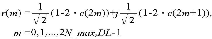
여기서, N_max,DL은 무선 통신 시스템에서 지원되는 최대 하향링크 전송 대역폭에 해당하는 자원블록의 개수이다. LTE에서 N_max,DL은 110이다. N_DL이 N_max,DL보다 작은 경우, 2×N_max,DL 길이로 생성된 복소 시퀀스 중 2×N_DL 길이의 일정 부분을 선택해서 공용 참조신호 시퀀스로 사용할 수 있다. c(i)는 PN 시퀀스이다. PN 시퀀스는 길이-31의 골드(Gold) 시퀀스에 의해 정의될 수 있다. 다음 수학식은 c(i)의 예를 나타낸다.Here, N_max and DL are the number of resource blocks corresponding to the maximum downlink transmission bandwidth supported in the wireless communication system. In LTE, N_max and DL are 110. If N_DL is smaller than N_max, DL, a certain portion of the 2 × N_DL length of the complex sequence generated with 2 × N_max, DL length can be selected and used as a common reference signal sequence. c (i) is the PN sequence. The PN sequence may be defined by a Gold sequence of length-31. The following equation shows an example of c (i).

여기서, Nc=1600이고, x(i)은 제1 m-시퀀스이고, y(i)는 제2 m-시퀀스이다. 예를 들어, 제1 m-시퀀스는 각 OFDM 심벌의 처음에서 x(0)=1, x(i)=0(i=1,2,...,30)으로 초기화(initialization)될 수 있다. 제2 m-시퀀스는 각 OFDM 심벌의 처음에서 셀 ID, 무선 프레임 내 슬롯 번호, 슬롯 내 OFDM 심벌 인덱스, CP의 길이 등에 따라 초기화될 수 있다. Where Nc = 1600, x (i) is the first m-sequence, and y (i) is the second m-sequence. For example, the first m-sequence may be initialized to x (0) = 1, x (i) = 0 (i = 1, 2, ..., 30) at the beginning of each OFDM symbol . The second m-sequence may be initialized according to the cell ID at the beginning of each OFDM symbol, the slot number in the radio frame, the OFDM symbol index in the slot, the length of the CP, and the like.
다음 수학식은 제2 m-시퀀스의 초기화의 예이다.The following equation is an example of initialization of the second m-sequence.

여기서, n_s는 무선 프레임 내 슬롯 번호이고, ℓ은 슬롯 내 OFDM 심벌 인덱스이고, N_cell_ID는 셀 ID이다. 노멀 CP인 경우, N_CP는 1이고, 확장된 CP인 경우, N_CP는 0이다. Here, n_s is a slot number in a radio frame, l is an OFDM symbol index in a slot, and N_cell_ID is a cell ID. N_CP is 1 when it is a normal CP, and N_CP is 0 when it is an extended CP.
상기 식으로 공용 참조신호 시퀀스를 생성하는 경우, 공용 참조신호 시퀀스는 안테나와는 무관하다. 따라서 동일한 OFDM 심벌에서 복수의 안테나 각각마다 공용 참조신호가 전송되는 경우, 상기 복수의 안테나 각각의 공용 참조신호 시퀀스는 동일하다. When generating the common reference signal sequence in this manner, the common reference signal sequence is independent of the antenna. Therefore, when a common reference signal is transmitted for each of a plurality of antennas in the same OFDM symbol, the common reference signal sequence of each of the plurality of antennas is the same.
참조 자원요소를 포함하는 OFDM 심벌마다 생성된 공용 참조신호 시퀀스는 공용 참조신호 패턴에 따라 참조 자원요소에 맵핑된다. 이때 공용 참조신호 시퀀스는 순서대로 부반송파 인덱스의 오름차순으로 참조 자원요소에 맵핑될 수 있다. 이때, 각 안테나마다 공용 참조신호 시퀀스가 생성되고, 각 안테나마다 공용 참조신호 시퀀스가 참조 자원요소에 맵핑된다. The common reference signal sequence generated for each OFDM symbol including the reference resource element is mapped to the reference resource element according to the common reference signal pattern. In this case, the common reference signal sequence can be mapped to the reference resource element in ascending order of the subcarrier index in order. At this time, a common reference signal sequence is generated for each antenna, and a common reference signal sequence is mapped to each reference resource element for each antenna.
도 11은 LTE에서 노멀 CP의 경우, 전용 참조신호의 맵핑 예를 나타낸다. 도 12는 LTE에서 확장된 CP의 경우, 전용 참조신호의 맵핑 예를 나타낸다. 11 shows an example of mapping of a dedicated reference signal in case of a normal CP in LTE. 12 shows an example of mapping of dedicated reference signals in case of CP extended in LTE.
도 11 및 12를 참조하면, R5는 안테나 #5를 통한 전용 참조신호 전송에 사용되는 자원요소를 나타낸다. LTE에서 전용 참조신호는 단일 안테나 전송을 위해 지원된다. 상위계층에 의해 PDSCH 상의 하향링크 데이터 전송 기법(transmission scheme)이 안테나 #5를 통한 단일 안테나 전송으로 설정된 경우에만, 전용 참조신호가 존재할 수 있고, PDSCH 복조를 위해 유효할 수 있다. 전용 참조신호는 PDSCH가 맵핑되는 자원블록 상에서만 전송될 수 있다. 전용 참조신호는 PDSCH가 맵핑되는 자원블록 내 참조 자원요소들의 집합에 대응된다. 기지국은 전용 참조신호에 미리 정의된 전용 참조신호 시퀀스를 곱하여 전송할 수 있다. 여기서, 기본 단위는 시간 영역에서 하나의 서브프레임 및 주파수 영역에서 하나의 자원블록이다. Referring to Figures 11 and 12, R5 represents a resource element used for dedicated reference signal transmission through
전용 참조신호는 공용 참조신호와 동시에 전송될 수 있다. 따라서 참조신호 오버헤드가 공용 참조신호만이 전송되는 경우의 참조신호 오버헤드와 비교하여 대단히 높아지게 된다. 단말은 공용 참조신호와 전용 참조신호를 같이 사용할 수 있다. 서브프레임 내 제어정보가 전송되는 제어영역에서 단말은 공용 참조신호를 사용하고, 서브프레임 내 나머지 데이터 영역에서 단말은 전용 참조신호를 사용할 수 있다. 예를 들어, 제어영역은 서브프레임의 제1 슬롯 내 OFDM 심벌 인덱스 ℓ이 0 내지 2인 OFDM 심벌들이다(도 4 참조).The dedicated reference signal can be transmitted simultaneously with the common reference signal. Therefore, the reference signal overhead becomes much higher than the reference signal overhead when only the common reference signal is transmitted. A terminal can use a common reference signal and a dedicated reference signal together. A terminal uses a common reference signal in a control region in which control information in a subframe is transmitted and a terminal can use a dedicated reference signal in a remaining data region in a subframe. For example, the control region is an OFDM symbol in which the OFDM symbol index l in the first slot of the subframe is 0 to 2 (see FIG. 4).
전용 참조신호의 참조신호 패턴인 전용 참조신호 패턴은 셀 내 모든 단말에게 공통될 수 있다. 다만 셀 간 간섭을 최소화시키기 위해, 전용 참조신호 패턴은 셀에 따라 정해질 수 있다. 전용 참조신호 시퀀스는 단말에 따라 정해질 수 있다. 따라서 셀 내 특정 단말만이 전용 참조신호를 수신할 수 있다. The dedicated reference signal pattern, which is a reference signal pattern of the dedicated reference signal, can be common to all terminals in the cell. However, in order to minimize the inter-cell interference, the dedicated reference signal pattern can be determined according to the cell. The dedicated reference signal sequence may be determined according to the UE. Therefore, only the specific terminal in the cell can receive the dedicated reference signal.
전용 참조신호 시퀀스는 서브프레임 단위로 생성될 수 있다. 전용 참조신호 시퀀스는 셀 ID, 하나의 무선 프레임 내 서브프레임의 위치, 단말 ID 등에 따라 달라질 수 있다. A dedicated reference signal sequence may be generated in units of subframes. The dedicated reference signal sequence may vary depending on the cell ID, the position of the subframe in one radio frame, the terminal ID, and the like.
기본 단위 내 전용 참조신호를 위한 참조 자원요소의 개수는 12이다. 즉, 기본 단위 내 R5의 개수는 12이다. PDSCH가 맵핑되는 자원블록의 개수를 N_PDSCH라 할 경우, 전용 참조신호를 위한 전체 R5의 개수는 12×N_PDSCH이다. 따라서 전용 참조신호 시퀀스의 길이는 12×N_PDSCH이다. 전용 참조신호 시퀀스의 길이는 단말이 PDSCH 전송을 위해 할당받는 자원블록의 개수에 따라 달라질 수 있다. The number of reference resource elements for a dedicated reference signal within a basic unit is 12. That is, the number of R5 in the basic unit is 12. When the number of resource blocks to which PDSCHs are mapped is N_PDSCH, the total number of R5s for dedicated RSs is 12 x N_PDSCH. Therefore, the length of the dedicated reference signal sequence is 12 x N_PDSCH. The length of the dedicated RS sequence may vary depending on the number of resource blocks allocated to the UE for PDSCH transmission.
다음 수학식은 전용 참조신호 시퀀스 r(m)의 예를 나타낸다. The following equation shows an example of the dedicated reference signal sequence r (m).

여기서, c(i)는 PN 시퀀스이다. c(i)는 수학식 2가 이용될 수 있다. 이때, 제2 m-시퀀스는 각 서브프레임의 처음에서 셀 ID, 하나의 무선 프레임 내 서브프레임의 위치, 단말 ID 등에 따라 초기화될 수 있다. Here, c (i) is a PN sequence. (2) can be used for c (i). At this time, the second m-sequence may be initialized according to the cell ID at the beginning of each sub-frame, the position of the sub-frame in one radio frame, the terminal ID, and the like.
다음 수학식은 제2 m-시퀀스의 초기화의 예이다.The following equation is an example of initialization of the second m-sequence.

여기서, n_s는 무선 프레임 내 슬롯 번호이고, N_cell_ID는 셀 ID이고, UE_ID는 단말 ID이다. Here, n_s is a slot number in a radio frame, N_cell_ID is a cell ID, and UE_ID is a terminal ID.
전용 참조신호 시퀀스는 PDSCH가 맵핑되는 자원블록 내에서 참조신호 패턴에 따라 참조 자원요소에 맵핑된다. 이때 전용 참조신호 시퀀스는 순서대로 상기 자원블록 내에서 우선 부반송파 인덱스의 오름차순, 다음에는 OFDM 심벌 인덱스의 오름차순으로 참조 자원요소에 맵핑된다. The dedicated reference signal sequence is mapped to the reference resource element according to the reference signal pattern in the resource block to which the PDSCH is mapped. At this time, dedicated reference signal sequences are sequentially mapped to the reference resource elements in ascending order of the priority subcarrier index in the resource block, and then in ascending order of the OFDM symbol index.
지금까지 LTE 시스템에서의 공용 참조신호 구조 및 전용 참조신호 구조에 대해 설명하였다. 하향링크에서 LTE 시스템은 1, 2 또는 4개의 안테나 전송이 지원된다. 즉, LTE 시스템이 적용되는 단말(이하, LTE 단말)은 최대 4개의 전송 안테나를 통해 전송되는 신호를 수신할 수 있다. LTE 시스템의 공용 참조신호 구조는 최대 4개 전송 안테나의 채널 추정이 가능하도록 설계되어 있다. The common reference signal structure and the dedicated reference signal structure in the LTE system have been described so far. In the downlink, LTE system supports 1, 2 or 4 antenna transmission. That is, a terminal to which an LTE system is applied (hereinafter referred to as an LTE terminal) can receive signals transmitted through up to four transmit antennas. The common reference signal structure of the LTE system is designed to allow channel estimation of up to 4 transmit antennas.
LTE-A 시스템은 8개의 전송 안테나까지 지원된다. 즉, LTE-A 시스템이 적용되는 단말(이하, LTE-A 단말)은 최대 8개의 전송 안테나를 통해 전송되는 신호를 수신할 수 있다. 따라서 LTE-A 시스템은 최대 8개 전송 안테나의 채널 추정이 가능하도록 참조신호가 전송되어야 한다.The LTE-A system supports up to eight transmit antennas. That is, a terminal to which an LTE-A system is applied (hereinafter referred to as an LTE-A terminal) can receive signals transmitted through up to eight transmit antennas. Therefore, the LTE-A system should transmit a reference signal to enable channel estimation of up to 8 transmit antennas.
그런데 셀 내에는 LTE 단말과 LTE-A 단말이 공존(coexising)할 수 있다. 따라서 LTE-A 시스템은 LTE 단말 및 LTE-A 단말을 함께 지원할 수 있도록 설계되어야 한다. 이를 위해, LTE-A 시스템은 LTE 시스템과 역호환성을 유지하도록 설계될 수 있다. However, LTE terminals and LTE-A terminals can coexist within the cell. Therefore, LTE-A system should be designed to support LTE terminal and LTE-A terminal together. To this end, the LTE-A system can be designed to maintain backward compatibility with LTE systems.
LTE-A 시스템에서 최대 8개의 안테나 전송이 지원되기 위해, LTE-A 시스템은 LTE-A 단말에게 최대 8개의 전송 안테나에 대한 참조신호를 모두 제공해야 한다. 그리고 LTE-A 시스템은 LTE 단말에게는 하향링크에서 1, 2 또는 4 전송 안테나 시스템으로 보이도록 구성되어야 한다. 이를 통해 LTE-A 시스템은 LTE 단말과 LTE-A 단말을 모두 지원할 수 있다. 이때, LTE-A 시스템에서 LTE 시스템의 공용 참조신호 구조가 최대한 유지될 수 있다. In order to support up to 8 antenna transmissions in the LTE-A system, the LTE-A system must provide all of the reference signals for up to 8 transmit antennas to the LTE-A terminal. And the LTE-A system should be configured to appear as a 1, 2, or 4 transmit antenna system in the downlink for the LTE terminal. Thus, LTE-A system can support both LTE terminal and LTE-A terminal. At this time, the common reference signal structure of the LTE system in the LTE-A system can be maintained as much as possible.
LTE 단말과 LTE-A 단말을 동시에 지원하는 시스템을 구성하기 위해, 적절한 참조신호 전송 장치 및 방법을 제공할 필요가 있다. LTE 단말이 LTE-A 시스템에서 동작하기 위한 참조신호 구조가 적절히 설계되어야 한다. It is necessary to provide an appropriate reference signal transmitting apparatus and method for configuring a system supporting both LTE terminals and LTE-A terminals at the same time. The reference signal structure for the LTE terminal to operate in the LTE-A system should be appropriately designed.
4 전송 안테나를 통한 MIMO 기법과 8 전송 안테나를 통한 MIMO 기법이 동일한 서브프레임 또는 동일한 무선 프레임에서 지원되기 위해, LTE 단말에 사용되는 제어채널은 4 전송 안테나를 통한 MIMO 기법으로 유지되어야 한다. 따라서 하향링크 서브프레임 내 제어영역(도 4 참조)은 LTE 시스템에서 지원되는 2 전송 안테나 또는 4 전송 안테나로 동작하도록 구성하는 것이 바람직하다. 4 transmission antenna and MIMO scheme using 8 transmission antennas are supported in the same subframe or the same radio frame, the control channel used for the LTE terminal should be maintained as a MIMO scheme through 4 transmission antennas. Accordingly, it is preferable that the control region in the DL subframe (see FIG. 4) is configured to operate with 2 transmit antennas or 4 transmit antennas supported by the LTE system.
8 전송 안테나 시스템에서 LTE를 위한 1, 2 또는 4 안테나 전송을 구현하는 방법으로 다음의 방법들이 사용될 수 있다. The following methods can be used as a method for implementing 1, 2, or 4 antenna transmission for LTE in the 8 transmit antenna system.
첫째, 8 전송 안테나 시스템에서 LTE를 위한 1, 2 또는 4 안테나 전송은 전송 안테나를 온/오프(on/off) 기법으로 구현될 수 있다. 8개의 전송 안테나 중 7, 6 또는 4개의 전송 안테나의 전력을 사용하지 않도록 온/오프함으로써 1, 2 또는 4 안테나 전송이 구현될 수 있다. 그런데 전송 안테나를 온/오프하는 기법은 전송 전력의 손실이 발생한다. First, the 1, 2 or 4 antenna transmission for LTE in the 8 Tx antenna system can be implemented by on / off technique of the Tx antenna. One, two, or four antenna transmissions may be implemented by turning on / off the power of seven, six, or four transmit antennas among eight transmit antennas. However, in the technique of turning on / off the transmission antenna, transmission power is lost.
둘째, 8 전송 안테나 시스템에서 LTE를 위한 1, 2 또는 4 안테나 전송은 가상 안테나(virtual antenna) 기법으로 구현될 수 있다. 전송 안테나를 온/오프하는 기법은 전송 전력의 손실이 발생하므로 가상 안테나 기법이 적용되는 것이 바람직하다. Second, one, two, or four antenna transmission for LTE in the 8 transmit antenna system can be implemented by a virtual antenna technique. It is preferable that the virtual antenna technique is applied because the transmission power is lost due to the technique of turning on / off the transmission antenna.
이하, 가상 안테나를 통한 참조신호 전송 방법 및 그 장치에 대해 상술한다. 이하에서 설명되는 내용은 LTE-A 시스템뿐 아니라, 일반적인 OFDM-MIMO 시스템에서 적용 가능하다. Hereinafter, a method of transmitting a reference signal through a virtual antenna and an apparatus thereof will be described in detail. The following description is applicable not only to the LTE-A system but also to a general OFDM-MIMO system.
셀 내에는 제1 시스템이 적용되는 단말과 제2 시스템이 적용되는 단말이 공존할 수 있다. 제2 시스템은 제1 시스템의 진화된 시스템이다. 일 예로, 제1 시스템은 LTE 시스템이고, 제2 시스템은 LTE-A 시스템일 수 있다. 다른 예로, 제1 시스템은 IEEE 802.16e 시스템이고, 제2 시스템은 IEEE 802.16m 시스템일 수 있다. In the cell, the terminal to which the first system is applied and the terminal to which the second system is applied can coexist. The second system is an evolved system of the first system. In one example, the first system may be an LTE system and the second system may be an LTE-A system. As another example, the first system may be an IEEE 802.16e system and the second system may be an IEEE 802.16m system.
제2 시스템은 제1 시스템에 비해 하향링크에서 지원되는 전송 안테나의 개수가 확장된 시스템이다. 제1 시스템은 하향링크에서 K개의 전송 안테나까지 지원되고, 제2 시스템은 하향링크에서 N개의 전송 안테나까지 지원된다(N>K). 예를 들어, 제1 시스템은 LTE 시스템(K=4)이고, 제2 시스템은 LTE-A 시스템(N=8)일 수 있다. The second system is a system in which the number of transmission antennas supported in the downlink is extended as compared with the first system. The first system supports up to K transmit antennas in the downlink and the second system supports up to N transmit antennas in the downlink (N> K). For example, the first system may be an LTE system (K = 4) and the second system may be an LTE-A system (N = 8).
도 13은 안테나 가상화 기법을 사용하는 전송기 구조의 예를 나타낸 블록도이다. 여기서, 전송기는 기지국 또는 단말의 일부분일 수 있다. 13 is a block diagram illustrating an example of a transmitter structure using an antenna virtualization technique. Here, the transmitter may be a base station or a part of a terminal.
도 13을 참조하면, 전송기(100)는 참조신호 생성기(110), 가상화부(virtualization unit, 120) 및 Nt개의 전송 안테나(190-1,...,190-Nt)를 포함한다. Nt개의 전송 안테나(190-1,...,190-Nt)는 물리적 안테나이다. 참조신호 생성기(110)는 가상화부(120)에 연결되고, 가상화부(120)는 Nt개의 전송 안테나(190-1,...,190-Nt)에 연결된다. Referring to FIG. 13, a
참조신호 생성기(110)는 K개의 참조신호 시퀀스를 생성하도록 형성된다(K<Nt). The
가상화부(120)는 각각의 K개의 참조신호 시퀀스를 각각의 K개의 가상 안테나 맵핑하여 각각의 K개의 참조신호 시퀀스 벡터를 생성하도록 형성된다. 하나의 참조신호 시퀀스를 하나의 가상 안테나에 맵핑하여 하나의 참조신호 시퀀스 벡터가 생성될 수 있다. 각각의 K개의 참조신호 시퀀스 벡터는 Nt개의 전송 안테나(190-1,...,190-Nt)를 통해 전송된다. The
이와 같이, Nt개의 전송 안테나를 포함하는 전송기(100)는 안테나 가상화를 통해 K개의 가상 안테나를 통해 참조신호를 전송할 수 있다. 단말 입장에서는 K개의 안테나를 통해 참조신호가 전송되는 것으로 보인다. 예를 들어, LTE-A 시스템에서, 8개의 전송 안테나를 포함하는 기지국은 안테나 가상화를 통해 1, 2 또는 4 가상 안테나를 통해 참조신호를 전송할 수 있다. Thus, the
K개 이하의 안테나 전송이 지원되는 경우, 참조신호는 가상 안테나 맵핑 방식으로 전송될 수 있다. 그런데 K개보다 많은 개수의 안테나 전송이 지원되는 경우, 참조신호 전송 방법이 문제된다. 즉, 4개 이하의 안테나 전송이 지원되는 LTE 단말은 가상 안테나 맵핑 방식으로 참조신호가 전송될 수 있으나, 4개보다 많은 개수의 안테나 전송이 지원되는 LTE-A 단말을 위한 참조신호 전송 방법이 문제된다. If less than K antenna transmissions are supported, the reference signal may be transmitted in a virtual antenna mapping scheme. However, when more than K antennas are supported, the reference signal transmission method is problematic. That is, although a reference signal can be transmitted using a virtual antenna mapping scheme for an LTE terminal supporting four or less antenna transmissions, a reference signal transmission method for an LTE-A terminal supporting more than four antenna transmissions is problematic do.
첫째, LTE-A 단말을 위한 참조신호는 물리적 안테나 맵핑 방식으로 전송될 수 있다. 둘째, LTE-A 단말을 위한 참조신호 역시 가상 안테나 맵핑 방식으로 전송될 수 있다. First, a reference signal for the LTE-A terminal can be transmitted in a physical antenna mapping manner. Second, a reference signal for an LTE-A terminal may also be transmitted using a virtual antenna mapping scheme.
먼저, LTE-A 단말을 위한 참조신호는 물리적 안테나 맵핑 방식으로 전송되는 경우를 설명한다. 이 경우, LTE 단말을 위한 참조신호만을 가상 안테나 맵핑 방식으로 전송하고, LTE-A 단말을 위한 참조신호는 물리적 안테나 맵핑 방식으로 전송한다. 또는 단말의 종류와는 상관없이 K개의 안테나 전송의 경우에는 가상 안테나 맵핑 방식이 적용되고, K개보다 많은 개수의 안테나 전송의 경우에는 물리적 안테나 맵핑 방식이 적용될 수 있다. 예를 들어, 4 전송 안테나 MIMO 기법을 위해서는 가상 안테나 맵핑을 적용하도록 구성되고, 8 전송 안테나 MIMO 기법을 위해서는 물리적 안테나 맵핑을 적용하도록 구성될 수 있다. 이 경우, 4 전송 안테나 MIMO 기법을 위해 사용된 참조신호는 8 전송 안테나 MIMO 기법을 위하여는 사용될 수 없다. 따라서 LTE-A 단말에게 8 전송 안테나 MIMO 기법을 위한 측정용 참조신호는 4 전송 안테나 MIMO 기법의 참조신호와는 별도로 전송되어야 한다. 이 경우 8 전송 안테나 MIMO 기법의 프리코딩이 좀 더 정확하게 사용될 수 있다. First, a case where a reference signal for an LTE-A terminal is transmitted in a physical antenna mapping scheme will be described. In this case, only the reference signal for the LTE terminal is transmitted using the virtual antenna mapping method, and the reference signal for the LTE-A terminal is transmitted using the physical antenna mapping method. A virtual antenna mapping method is applied to K antenna transmissions regardless of the type of terminal, and a physical antenna mapping method can be applied to a case where there are more than K antenna transmissions. For example, it may be configured to apply virtual antenna mapping for a 4-transmit antenna MIMO scheme, and may be configured to apply a physical antenna mapping for an 8-transmit antenna MIMO scheme. In this case, the reference signal used for the 4 transmit antenna MIMO scheme can not be used for the 8 transmit antenna MIMO scheme. Therefore, the measurement reference signal for the 8-transmit antenna MIMO scheme is transmitted separately from the reference signal of the 4-transmit antenna MIMO scheme to the LTE-A UE. In this case, precoding of the 8 transmit antenna MIMO scheme can be used more accurately.
다음, LTE-A 단말을 위한 참조신호 역시 가상 안테나 맵핑 방식으로 전송되는 경우를 설명한다. 이 경우 LTE-A 단말을 위해 8개의 가상 안테나가 구성된다. LTE 단말을 위해서는 구성된 8개의 가상 안테나 중 1, 2 또는 4개의 가상 안테나가 선택된다. Next, a case where a reference signal for an LTE-A terminal is also transmitted through a virtual antenna mapping method will be described. In this case, eight virtual antennas are configured for the LTE-A terminal. For the LTE terminal, one, two, or four virtual antennas out of the eight virtual antennas configured are selected.
도 14는 하나의 가상 안테나를 통해 참조신호가 전송되는 무선 통신 시스템의 예를 나타낸 블록도이다. 14 is a block diagram illustrating an example of a wireless communication system in which a reference signal is transmitted through one virtual antenna.
도 14를 참조하면, 전송기(200)는 참조신호 생성기(210), 가상화부(220) 및 Nt개의 전송 안테나(290-1,...,290-Nt)를 포함한다(Nt는 자연수). Nt개의 전송 안테나(290-1,...,290-Nt)는 물리적 안테나이다. 참조신호 생성기(210)는 가상화부(220)에 연결되고, 가상화부(220)는 Nt개의 전송 안테나(290-1,...,290-Nt)에 연결된다. 수신기(300)는 채널 추정부(310) 및 Nr개의 수신 안테나(390-1,...,390-Nr)를 포함한다. 전송기(200)는 기지국의 일부분이고, 수신기(300)는 단말의 일부분일 수 있다. Referring to FIG. 14, the
Nt개의 전송 안테나(290-1,...,290-Nt) 및 Nr개의 수신 안테나(390-1,...,390-Nr) 사이에는 MIMO 채널 행렬 H가 형성된다. MIMO 채널 행렬 H의 크기는 Nr×Nt이다. 수신 안테나의 개수가 1인 경우, MIMO 채널 행렬은 행 벡터(row vector)가 된다. 일반적으로 행렬은 행 벡터 및 열 벡터(column vector)까지 포함하는 개념이다. A MIMO channel matrix H is formed between Nt transmission antennas 290-1 through 290-Nt and Nr reception antennas 390-1 through 390-Nr. The size of the MIMO channel matrix H is Nr x Nt. If the number of receive antennas is 1, the MIMO channel matrix becomes a row vector. In general, a matrix includes a row vector and a column vector.
참조신호 생성기(210)는 참조신호 시퀀스 #i(ri(m))을 생성하도록 형성된다. 참조신호 시퀀스 #i(ri(m))는 참조신호 패턴 #i에 따라 맵핑된 참조신호 시퀀스이다. 여기서, i는 참조신호 패턴을 지시하는 패턴 인덱스이다. m은 시간-주파수 자원 인덱스에 대응될 수 있다. 참조신호 패턴이란 참조신호 시퀀스 전송에 사용되는 시간-주파수 자원 패턴이다. 예를 들어, 참조신호 패턴 #0 내지 참조신호 패턴 #3에는 도 7의 참조신호 구조가 이용할 수 있다. The
또는 참조신호 시퀀스 #i(ri(m))은 전송 안테나 #i에 대한 참조신호 패턴에 따라 맵핑된 참조신호 시퀀스일 수 있다(i=0,1,...,Nt-1). 이 경우, Nt개의 전송 안테나 각각마다 서로 다른 참조신호 패턴이 사용될 수 있다. Or the reference signal sequence #i (r i (m)) may be a reference signal sequence mapped according to the reference signal pattern for the transmission antenna #i (i = 0, 1, ..., Nt-1). In this case, different reference signal patterns may be used for each of Nt transmission antennas.
가상화부(220)는 참조신호 시퀀스 #i(ri(m))를 가상 안테나 #i로 맵핑되도록 형성된다. 참조신호 시퀀스 #i(ri(m))를 가상 안테나 #i로 맵핑하기 위해 가상 안테나 행렬(virtual antenna matrix, V)을 사용한다. The
가상 안테나 행렬의 행의 개수는 물리적 전송 안테나의 개수와 같고, 가상 안테나 행렬의 열의 개수는 가상 안테나의 개수와 같도록 구성될 수 있다. LTE-A 단말을 위한 참조신호 역시 가상 안테나 맵핑 방식으로 전송되는 경우, Nt개의 가상 안테나가 구성될 수 있다. 이 경우, 가상 안테나 행렬의 크기는 Nt×Nt이다. The number of rows of the virtual antenna matrix is equal to the number of physical transmission antennas and the number of columns of the virtual antenna matrix is equal to the number of virtual antennas. When a reference signal for an LTE-A terminal is also transmitted through a virtual antenna mapping scheme, Nt virtual antennas can be configured. In this case, the size of the virtual antenna matrix is Nt x Nt.
다음 수학식은 Nt가 8인 경우, 가상 안테나 행렬의 예를 나타낸다. The following equation shows an example of a virtual antenna matrix when Nt = 8.

여기서, v i는 가상 안테나 행렬의 i번째 열 벡터로 참조신호를 가상 안테나 #i로 맵핑하기 위한 가상 안테나 벡터 #i이다. vij는 가상 안테나 행렬의 복소수 계수(complex coefficient)이다(i∈{0,1,...,7}, j∈{0,1,...,7}). 복소수 계수는 상황에 따라 여러 가지 형태로 구성 가능하다. Here, v i is an i-th column vector of a virtual antenna matrix, and is a virtual antenna vector #i for mapping a reference signal to a virtual antenna #i. v ij is a complex coefficient of a virtual antenna matrix (i? {0,1, ..., 7}, j? {0,1, ..., 7}). The complex coefficient can be configured in various forms depending on the situation.
가상 안테나 행렬은 유니터리 행렬(unitary matrix) 형태로 구성할 수 있다. 가상 안테나 행렬이 유니터리 행렬인 경우, 모든 전송 안테나에 균등하게 전력이 분배될 수 있다. The virtual antenna matrix can be configured as a unitary matrix. If the virtual antenna matrix is a unitary matrix, power can be evenly distributed to all transmit antennas.
참조신호 시퀀스 #i이 가상 안테나 #i로 맵핑된 참조신호 시퀀스 벡터 #i를 다음 수학식과 같이 나타낼 수 있다. The reference signal sequence vector #i mapped to the virtual antenna #i by the reference signal sequence #i can be expressed by the following equation.
![]()
![]()
여기서, ri(m)은 참조신호 시퀀스 #i이고, v i는 가상 안테나 행렬의 i번째 열 벡터로 가상 안테나 벡터 #i이고, R i(m)는 참조신호 시퀀스 벡터 #i이다. Here, r i (m) is a reference signal sequence #i, v i is a virtual antenna vector #i as an i-th column vector of a virtual antenna matrix, and R i (m) is a reference signal sequence vector #i.
전송기(200)는 Nt개의 전송 안테나(290-1,...,290-Nt)를 통해서 참조신호 시퀀스 벡터 #i(R i(m))를 전송한다.The
수신기(300)는 Nr개의 수신 안테나(390-1,...,390-Nr)를 통해 수신 신호 벡터 y=[y1 y2 ... yNr]T를 수신한다. 수신 신호 벡터 y는 다음 수학식과 같이 나타낼 수 있다. The

여기서, n=[n1 n2 ... nNr]T은 잡음 벡터이다.Where n = [n 1 n 2 ... n Nr ] T is the noise vector.
채널 추정부(310)는 수신 신호 벡터로부터 가상 안테나 #i의 가상 안테나 채널인 가상 안테나 채널 #i(h i)를 추정하도록 형성된다. 채널 추정부(310)는 참조신호 시퀀스 #i(ri(m))을 알고 있으므로, 가상 안테나 채널 #i(h i)를 추정할 수 있다. The
여기서는 하나의 가상 안테나를 통해 하나의 참조신호 시퀀스를 전송하는 경우를 도시하였으나, K개의 가상 안테나를 통해 K개의 참조신호 시퀀스가 전송될 수 도 있다. LTE 단말에 K개의 안테나 전송이 적용되는 경우, 기지국은 Nt개의 가상 안테나를 구성하여 K개의 가상 안테나를 선택하여 참조신호를 전송할 수 있다. Here, a case in which one reference signal sequence is transmitted through one virtual antenna is shown, but K reference signal sequences may be transmitted through K virtual antennas. When K antenna transmission is applied to the LTE terminal, the base station can configure Nt virtual antennas to select K virtual antennas and transmit reference signals.
각각의 K개의 참조신호 시퀀스 및 각각의 K개의 가상 안테나 벡터를 기반으로 각각의 K개의 참조신호 시퀀스 벡터가 생성되고, 각각의 K개의 참조신호 시퀀스 벡터는 Nt개의 전송 안테나를 통해 전송될 수 있다. 여기서, 각각의 K개의 가상 안테나 벡터는 가상 안테나 행렬로부터 선택되는 서로 다른 열 벡터일 수 있다. Each K reference signal sequence vector is generated based on each K reference signal sequence and each K virtual antenna vector, and each K reference signal sequence vector can be transmitted through Nt transmission antennas. Here, each of the K virtual antenna vectors may be a different column vector selected from the virtual antenna matrix.
가상 안테나 행렬은 K에 상관없이 동일한 가상 안테나 행렬을 사용할 수 있다. 또는 K에 따라 가상 안테나 행렬을 다르게 사용할 수 있다. 예를 들어, 기지국은 LTE 단말을 위해 1, 2 또는 4 안테나 전송에 따라 동일한 가상 안테나 행렬을 사용하거나, 다른 가상 안테나 행렬을 사용할 수도 있다. The virtual antenna matrix can use the same virtual antenna matrix regardless of K. [ Alternatively, the virtual antenna matrix can be used differently according to K. For example, the base station may use the same virtual antenna matrix for one, two, or four antenna transmissions for an LTE terminal, or use another virtual antenna matrix.
이하, 가상 안테나 행렬의 구체적인 예를 설명한다. Hereinafter, a specific example of the virtual antenna matrix will be described.
1. 8개의 가상 안테나를 구성하여 4개의 가상 안테나가 선택되는 경우1. When four virtual antennas are selected by configuring eight virtual antennas
LTE 단말에 4 안테나 전송이 적용되는 경우, 기지국은 8개의 가상 안테나를 구성하여 4개의 가상 안테나를 선택하여 참조신호를 전송할 수 있다. 이 경우, 다음과 같은 가상 안테나 행렬을 구성할 수 있다. When 4-antenna transmission is applied to an LTE terminal, the base station may configure eight virtual antennas to select four virtual antennas and transmit reference signals. In this case, the following virtual antenna matrix can be constructed.
다음 수학식은 가상 안테나 행렬의 일 예이다.The following equation is an example of a virtual antenna matrix.

이 경우, 가상 안테나 벡터가 시간-주파수 자원의 위치에 상관없이 고정된다. 시간-주파수 자원에 상관없이 특정 빔(beam)이 형성된다. 여기서, 시간-주파수 자원이란 부반송파, 자원요소 또는 특정 자원일 수 있다. In this case, the virtual antenna vector is fixed regardless of the position of the time-frequency resource. A specific beam is formed regardless of the time-frequency resource. Here, the time-frequency resource may be a subcarrier, a resource element, or a specific resource.
다음 수학식은 가상 안테나 행렬의 다른 예이다. The following equation is another example of a virtual antenna matrix.

여기서, k는 시간-주파수 자원을 지시하는 시간-주파수 자원 인덱스이고, di는 위상(phase)이다(0≤di<2π, i=1,2,3,4). 예를 들어, k는 부반송파 인덱스, 자원요소 인덱스 또는 특정 자원 인덱스일 수 있다. 시간-주파수 자원에 따라 빔이 형성될 수 있다. Here, k is a time-frequency resource index indicating a time-frequency resource, and d i is a phase (0? D i <2 ?, i = 1, 2, 3, 4). For example, k may be a subcarrier index, a resource element index, or a specific resource index. A beam can be formed according to time-frequency resources.
이외의 다른 형태의 임의의 행렬이 가상 안테나 행렬로 사용될 수 있다. 예를 들어, 가상 안테나 행렬은 위상 대각 행렬(phase diagonal matrix) 및 상수 모듈러스 행렬(constant modulus matrix)의 결합으로 구성될 수 있다. 상수 모듈러스 행렬은 행렬의 각 요소가 '0'이 아닌 같은 크기를 갖는 행렬이다. 예를 들어, 상수 모듈러스 행렬 U는 DFT(discrete Fourier transform) 행렬 또는 월시(Walsh) 행렬일 수 있다. 예를 들어, 가상 안테나 행렬은 다음 수학식과 같이 나타낼 수 있다. Any other type of matrix may be used as the virtual antenna matrix. For example, the virtual antenna matrix may be composed of a combination of a phase diagonal matrix and a constant modulus matrix. The constant modulus matrix is a matrix whose elements are not equal to '0' but have the same size. For example, the constant modulus matrix U may be a discrete Fourier transform (DFT) matrix or a Walsh matrix. For example, the virtual antenna matrix can be expressed by the following equation.

여기서, 행렬 U는 상수 모듈러스 행렬이고, k는 시간-주파수 자원을 지시하는 시간-주파수 자원 인덱스이고, di는 위상이다(0≤di<2π, i=0,1,...,7). 상수 모듈러스 행렬 U는 행렬의 각 요소의 크기가 같은 유니터리 행렬일 수 있다. k는 부반송파 인덱스, 자원요소 인덱스 또는 특정 자원 인덱스일 수 있다. Where matrix U is a constant modulus matrix, k is a time-frequency resource index indicating a time-frequency resource, and d i is a phase (0? D i <2 ?, i = 0,1, ..., 7 ). The constant modulus matrix U may be a unitary matrix having the same size of each element of the matrix. k may be a subcarrier index, a resource element index, or a specific resource index.
위상 di가 '0'인 경우(i=0,1,...,7), 가상 안테나 행렬 V는 U가 된다. 위상 di는 고정된 값을 사용하거나, 기지국에 의해 결정될 수 있다(i=0,1,...,7). When the phase d i is '0' (i = 0, 1, ..., 7), the virtual antenna matrix V becomes U. The phase d i can use a fixed value or be determined by the base station (i = 0, 1, ..., 7).
B. 8개의 가상 안테나를 구성하여 2개의 가상 안테나가 선택되는 경우B. When two virtual antennas are selected by configuring eight virtual antennas
LTE 단말에 2 안테나 전송이 적용되는 경우, 기지국은 8개의 가상 안테나를 구성하여 2개의 가상 안테나를 선택하여 참조신호를 전송할 수 있다. 이 경우, 다음과 같은 가상 안테나 행렬을 구성할 수 있다. When two-antenna transmission is applied to an LTE terminal, the base station can configure eight virtual antennas, select two virtual antennas, and transmit reference signals. In this case, the following virtual antenna matrix can be constructed.
다음 수학식은 가상 안테나 행렬의 일 예이다.The following equation is an example of a virtual antenna matrix.

가상 안테나 행렬은 DFT 행렬 또는 월시 행렬을 확장하여 구성될 수 있다. 예를 들어, 가상 안테나 행렬은 다음 수학식과 같이 나타낼 수 있다. The virtual antenna matrix may be constructed by extending a DFT matrix or a Walsh matrix. For example, the virtual antenna matrix can be expressed by the following equation.

여기서, D 4 ×4는 4×4 크기의 DFT 행렬이고, W 4 ×4는 4×4 크기의 월시 행렬이다. 이와 같이, 가상 안테나 행렬은 DFT 행렬 또는 월시 행렬을 블록 대각(block diagonal) 형태로 확장하여 구성될 수 있다. Here, D 4 × 4 is a 4 × 4 DFT matrix, and W 4 × 4 is a 4 × 4 Walsh matrix. In this manner, the virtual antenna matrix can be constructed by extending a DFT matrix or a Walsh matrix into a block diagonal form.
가상 안테나 행렬은 수학식 13의 행렬의 열 치환(row permutation) 형태로 구성될 수 있다. 이를 다음 수학식과 같이 나타낼 수 있다. The virtual antenna matrix may be configured in the form of a row permutation of the matrix of Equation (13). This can be expressed as the following equation.

여기서, P 8 ×8은 8×8 크기의 순열 행렬(permutation matrix)이다. 순열 행렬은 정사각 행렬의 모든 원소가 0 또는 1이고, 각 행이나 열은 오직 하나의 1만 포함하고 있는 행렬이다. Here, P 8 × 8 is an 8 × 8 permutation matrix. A permutation matrix is a matrix in which all elements of a square matrix are 0 or 1, and each row or column contains only one.
수학식 12 내지 14 각각의 행렬에 위상 대각 행렬이 결합된 행렬이 가상 안테나 행렬로 구성될 수도 있다.A matrix in which the phase diagonal matrix is combined with each matrix of Equations (12) to (14) may be configured as a virtual antenna matrix.
이와 같이, 가상 안테나 행렬은 LTE 단말을 지원하는 전송 안테나의 개수에 따라 다르게 구성될 수 있다. 또한 특정 개수(예를 들어, 1, 2 또는 4개)의 전송 안테나를 위한 가상 안테나 행렬은 하나 이상으로 구성해 놓을 수도 있다. 이 경우, 전송 기법, 서브프레임, 무선 프레임, 중계 노드(relay node) 등의 상황에 따라 다른 가상 안테나 행렬이 사용될 수 있다. As described above, the virtual antenna matrix can be configured differently according to the number of transmission antennas supporting the LTE terminal. In addition, one or more virtual antenna matrices for a certain number of transmit antennas (e.g., 1, 2, or 4) may be configured. In this case, different virtual antenna matrices may be used depending on a transmission technique, a subframe, a radio frame, a relay node, and the like.
전송 기법은 기지국이 단말에게 하향링크 데이터를 전송하는 기법일 수 있다. 전송 기법에는 단일 안테나 기법, MIMO 기법 등이 있다. MIMO 기법에는 전송 다이버시티 기법, 개루프(open-loop) 공간 다중화 기법, 폐루프(closed-loop) 공간 다중화 기법, MU-MIMO(multiple user-MIMO) 기법 등이 있다. 전송 기법은 RRC(radio resource control)와 같은 상위계층(higher layer) 시그널링에 의해 반정적으로(semi-statically) 설정될 수 있다. The transmission scheme may be a scheme in which the BS transmits downlink data to the MS. The transmission scheme includes a single antenna scheme and a MIMO scheme. The MIMO scheme includes a transmit diversity scheme, an open-loop spatial multiplexing scheme, a closed-loop spatial multiplexing scheme, and a multiple user-MIMO (MIMO) scheme. The transmission scheme can be set semi-statically by higher layer signaling, such as radio resource control (RRC).
이와 같이, Nt개의 전송 안테나를 포함하는 전송기는 안테나 가상화를 통해 K개의 가상 안테나를 통해 참조신호를 전송할 수 있다. 이를 통해 K개의 안테나 전송이 지원되는 LTE 단말에게 참조신호가 전송될 수 있다. Thus, a transmitter including Nt transmit antennas can transmit a reference signal via K virtual antennas through antenna virtualization. Accordingly, a reference signal can be transmitted to an LTE terminal supporting K antenna transmissions.
그런데 Nt개의 안테나 전송이 지원되는 LTE-A 단말을 위한 참조신호 역시 가상 안테나 맵핑 방식으로 전송되는 경우, 나머지 Nt-K개의 가상 안테나를 통한 참조신호 역시 전송되어야 한다. 다음과 같은 방법이 사용될 수 있다. However, when a reference signal for an LTE-A terminal supporting Nt antenna transmission is also transmitted in a virtual antenna mapping scheme, a reference signal through the remaining Nt-K virtual antennas must also be transmitted. The following method can be used.
1. 가상 안테나 재설정(virtual antenna reconfiguration)1. Virtual antenna reconfiguration
가상 안테나의 구성은 가상 안테나 벡터 #i(v i)에 의해 채널특성이 결정된다. 따라서 가상 안테나 벡터 #i(v i)를 다르게 구성하면 다른 가상 안테나를 통해 참조신호가 전송되는 효과를 얻을 수 있다. The configuration of the virtual antenna is determined by the virtual antenna vector #i ( v i ). Therefore, if the virtual antenna vector #i ( v i ) is configured differently, a reference signal is transmitted through another virtual antenna.
참조신호 시퀀스 벡터 #j는 다음 수학식과 같이 구성될 수 있다. The reference signal sequence vector #j can be constructed as shown in the following equation.
![]()
![]()
여기서, rj(m)은 참조신호 시퀀스 #j이고, v i는 가상 안테나 행렬의 i번째 열 벡터로 가상 안테나 벡터 #i이고, R j(m)는 참조신호 시퀀스 벡터 #j이다. 즉, 참조신호 시퀀스 벡터 #j는 참조신호 시퀀스 #j가 가상 안테나 #i로 맵핑된 것이다. i는 가상 안테나 인덱스이고, j는 참조신호 패턴을 지시하는 패턴 인덱스이다. 가상 안테나 인덱스 i와 패턴 인덱스 j의 값을 일정 시간 구간 동안 다르게 적용하고, 이를 LTE-A 단말에게 알려줄 수 있다. 이를 통해, LTE-A 단말이 8개의 가상 안테나 채널 정보를 모두 얻을 수 있도록 구성될 수 있다. Here, r j (m) is a reference signal sequence #j, v i is a virtual antenna vector #i as an i-th column vector of a virtual antenna matrix, and R j (m) is a reference signal sequence vector #j. That is, the reference signal sequence vector #j is the reference signal sequence #j mapped to the virtual antenna #i. i is a virtual antenna index, and j is a pattern index indicating a reference signal pattern. It is possible to apply the values of the virtual antenna index i and the pattern index j differently for a predetermined time interval and notify the LTE-A UE of the value. Thus, the LTE-A terminal can be configured to obtain all eight virtual antenna channel information.
예를 들어, LTE 단말이 8개의 가상 안테나 중 4개의 가상 안테나를 선택하여 사용하는 경우를 가정한다. LTE 단말은 항상 동일한 4개의 가상 안테나를 사용하는 것이 아니라 시간에 따라 다른 가상 안테나를 사용할 수도 있다. 이때, LTE 단말은 채널의 변화만을 감지할 뿐 다른 가상 안테나로부터 신호가 전송됐는지 여부를 구분할 수 없다. 하지만 LTE-A 단말은 4개의 가상 안테나의 변화를 알 수 있고 이를 통하여 나머지 4개의 가상 안테나에 대한 정보를 추가적으로 얻을 수 있다. 모든 가상 안테나 벡터는 모든 LTE-A 단말에 명백(transparent)하게 구현될 수 있다. For example, it is assumed that an LTE terminal selects and uses four virtual antennas out of eight virtual antennas. The LTE terminal does not always use the same four virtual antennas but may use another virtual antenna depending on the time. At this time, the LTE terminal only detects a change of a channel, and can not distinguish whether or not a signal is transmitted from another virtual antenna. However, the LTE-A terminal can know the change of the four virtual antennas and can additionally obtain information about the remaining four virtual antennas. All virtual antenna vectors may be implemented transparently to all LTE-A terminals.
예를 들어, 제1 구간에는 참조신호 시퀀스 #0가 가상 안테나 #0를 통해 전송된다고 가정한다(R 0(m)=v 0r0(m)). 이 경우, LTE-A 단말은 가상 안테나 채널 #0(h 0=Hv 0)에 대한 정보를 얻을 수 있다. 제2 구간에는 참조신호 시퀀스 #0가 가상 안테나 #3를 통해 전송된다고 가정한다(R 0(m)=v 3r0(m)). 이 경우, LTE-A 단말은 가상 안테나 채널 #3(h 3=Hv 3)에 대한 정보를 얻을 수 있다. 예를 들어, 제1 구간 및 제2 구간은 각각 서로 다른 서브프레임 또는 서로 다른 무선 프레임일 수 있다. 이를 통해, LTE-A 단말은 제1 구간 및 제2 구간에서 모두 동일한 시간-주파수 위치에서 전송되는 참조신호 시퀀스를 통해 서로 다른 가상 안테나 채널에 대한 정보를 얻을 수 있다. 동일한 시간-주파수 위치에서 전송되는 참조신호 시퀀스는 동일한 참조신호 패턴을 사용하는 참조신호 시퀀스라 할 수 있다. For example, it is assumed that the reference
2. 가상 안테나 그룹 교환(virtual antenna group swapping)2. Virtual antenna group swapping
Nt개의 가상 안테나는 K개의 가상 안테나를 포함하는 제1 가상 안테나 그룹과 Nt-K개의 가상 안테나를 포함하는 제2 가상 안테나 그룹과 같이 두 개의 가상 안테나 그룹으로 정할 수 있다. 예를 들어, Nt는 8이고, K는 4일 수 있다. 제1 가상 안테나 그룹(G1)과 제2 가상 안테나 그룹(G2)이 제1 구간(t1)과 제2 구간(t2)에서 서로 가상 안테나 벡터가 교환되도록 할 수 있다. 이 경우, 모든 가상 안테나 벡터에 의해 생성되는 Nt개의 가상 안테나 채널이 고정된 참조신호 시퀀스 위치에서 얻을 수 있도록 구성될 수 있다. The Nt virtual antennas can be defined as two virtual antenna groups, such as a first virtual antenna group including K virtual antennas and a second virtual antenna group including Nt-K virtual antennas. For example, Nt may be 8, and K may be 4. It is possible to exchange virtual antenna vectors between the first virtual antenna group G1 and the second virtual antenna group G2 in the first section t1 and the second section t2. In this case, Nt virtual antenna channels generated by all the virtual antenna vectors can be configured to be obtained at a fixed reference signal sequence position.
일 예로, 제1 구간(t1)에서 제1 가상 안테나 그룹(G1)과 제2 가상 안테나 그룹(G2)은 다음 수학식과 같다. For example, the first virtual antenna group G1 and the second virtual antenna group G2 in the first section t1 are expressed by the following equations.

제2 구간(t2)에서 제1 가상 안테나 그룹(G1)과 제2 가상 안테나 그룹(G2)은 다음 수학식과 같이 교환될 수 있다. In the second section t2, the first virtual antenna group G1 and the second virtual antenna group G2 may be exchanged as shown in the following equation.
가상 안테나 그룹 교환은 측정 공용 참조신호(measurement common RS) 전송주기에만 발생할 수도 있다. 제1 가상 안테나 그룹(G1)의 가상 안테나 벡터와 제2 가상 안테나 그룹(G2)의 가상 안테나 벡터가 측정을 위한 참조신호가 전송되어야 하는 서브프레임에서만 순간적으로 교환되어 전송될 수 있다. The virtual antenna group exchange may occur only in the measurement common RS transmission period. The virtual antenna vector of the first virtual antenna group G1 and the virtual antenna vector of the second virtual antenna group G2 can be instantaneously exchanged only in the subframe in which the reference signal for measurement is to be transmitted.
모든 가상 안테나 벡터는 LTE-A 단말에게 명백하게 구현될 수 있다. 예를 들어, LTE-A 단말은 참조신호 시퀀스 #0 내지 #3을 통하여 가상 안테나 #0 내지 #3 또는 가상 안테나 #4 내지 #7의 채널 정보를 수신한다. 가상 안테나 그룹이 교환되는 구간에서 LTE-A 단말은 나머지 가상 안테나의 채널 정보를 수신할 수 있게 된다. 가상 안테나 그룹이 교환되는 구간은 서브프레임일 수 있다. All virtual antenna vectors can be explicitly implemented in an LTE-A terminal. For example, the LTE-A terminal receives channel information of
3. 가상 안테나 선택(virtual antenna selection)3. Virtual antenna selection
기지국은 Nt개의 가상 안테나 중 K개의 가상 안테나를 임의로 선택하여 K개의 가상 안테나에 대한 정보인 가상 안테나 정보를 LTE-A 단말에게 알려줄 수 있다. 이때, K개의 가상 안테나는 시간에 따라 변할 수 있다. 선택된 K개의 가상 안테나에 대한 가상 안테나 정보는 일정 주기마다 전송될 수 있다. 또는 Nt개의 가상 안테나 중 K개의 가상 안테나가 선택되는 패턴을 미리 정해놓을 수도 있다. A base station can arbitrarily select K virtual antennas out of Nt virtual antennas and inform virtual terminal information of K virtual antennas to the LTE-A terminal. At this time, the K virtual antennas may change with time. The virtual antenna information for the selected K virtual antennas may be transmitted at regular intervals. Alternatively, a pattern in which K virtual antennas among Nt virtual antennas are selected may be predetermined.
4. 측정용 참조신호 전송 방법(measurement RS transmission method)4. Measurement RS transmission method (Measurement RS transmission method)
상기 설명된 가상 안테나 재설정, 가상 안테나 교환, 가상 안테나 선택 등의 방법을 이용하여 Nt개의 전송 안테나 MIMO 기법을 위한 측정용 참조신호가 전송될 수 있다. A measurement reference signal for the Nt transmit antenna MIMO techniques may be transmitted using the above-described virtual antenna reset, virtual antenna exchange, virtual antenna selection, and the like.
예를 들어, LTE-A 시스템에서 측정용 참조신호의 참조신호 패턴은 {r0(m), r1(m), r2(m), r3(m)}만이 전송된다고 가정한다. 이 경우, 도 7의 참조신호 패턴만으로 8개의 전송 안테나 MIMO 기법을 위한 측정용 참조신호가 전송될 수 있다. 8개의 전송 안테나 MIMO 기법을 위해 LTE-A 단말은 8개의 가상 안테나 채널을 모두 알아야 한다. For example, in the LTE-A system, it is assumed that the reference signal pattern of the reference signal for measurement is transmitted only in {r 0 (m), r 1 (m), r 2 (m), r 3 (m). In this case, a reference signal for measurement for eight transmit antenna MIMO schemes can be transmitted using only the reference signal pattern of FIG. For eight transmit antenna MIMO schemes, the LTE-A terminal needs to know all eight virtual antenna channels.
상기 설명된 3가지 방법 등으로 시간에 따라 다른 가상 안테나 벡터를 곱하여 전송함으로써, 일정 시간이 지난 후 LTE-A 단말이 모든 가상 안테나 채널 정보를 얻을 수 있도록 구성할 수 있다. By multiplying different virtual antenna vectors over time by the above-described three methods or the like, the LTE-A terminal can obtain all the virtual antenna channel information after a predetermined time elapses.
가상 안테나 벡터가 변하는 주기는 CQI(channel quality indicator), PMI(precoding matrix index) 및/또는 RI(rank indicator) 피드백 주기에 따라 변하도록 구성할 수 있다. CQI는 채널에 적합한 MCS 레벨을 지시할 수 있다. 또는 CQI는 채널의 양자화(quantization) 정보이거나 유효한(effective) 채널의 양자화 정보일 수 있다. PMI는 채널에 적합한 코드북 인덱스를 지시한다. RI는 채널의 랭크를 지시한다. 예를 들어, CQI, PMI 및 RI의 피드백 주기 중 피드백 주기가 가장 빠른 정보에 따라 가상 안테나 벡터가 변하도록 할 수 있다. The period in which the virtual antenna vector changes may be configured to vary according to a channel quality indicator (CQI), a precoding matrix index (PMI), and / or a rank indicator feedback period. The CQI may indicate an appropriate MCS level for the channel. Or the CQI may be the quantization information of the channel or the quantization information of the effective channel. The PMI indicates a codebook index suitable for the channel. The RI indicates the rank of the channel. For example, the feedback period of CQI, PMI, and RI may be changed so that the virtual antenna vector changes according to the information with the fastest feedback period.
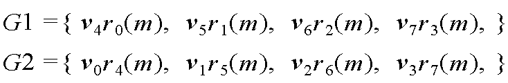
예를 들어, 피드백 주기가 가장 빠른 정보는 CQI이고, CQI의 피드백 주기는 5ms라고 가정한다. 5ms 주기마다 가상 안테나를 변화시킬 수 있다. 예를 들어, 5ms 주기마다 G1_v(1)={v 0r0(m), v 1r1(m), v 2r2(m), v 3r3(m)}과 G2_v(2)={v 4r0(m), v 5r1(m), v 6r2(m), v 7r3(m)}이 번갈아 전송되도록 구성될 수 있다. LTE-A 단말은 주기 안에 8개의 가상 안테나 채널을 모두 수신할 수 있다. LTE 단말은 시간 채널의 변화만 감지할 뿐 동작하는데 아무런 문제를 일으키지 않는다. For example, it is assumed that the information with the fastest feedback period is the CQI and the feedback period with the CQI is 5 ms. The virtual antenna can be changed every 5ms period. For example, 5ms period for each G1_v (1) = {v 0 r 0 (m), v 1 r 1 (m), v 2 r 2 (m), v 3 r 3 (m)} and G2_v (2) = { v 4 r 0 (m), v 5 r 1 (m), v 6 r 2 (m), v 7 r 3 (m)}. An LTE-A terminal can receive all eight virtual antenna channels within a period. The LTE terminal only detects a change in the time channel and does not cause any problem in operation.
또는 G1_v(1)이 계속 전송되다가 피드백 주기에 해당되는 서브프레임에서만 G2_v(2)가 일시적으로 전송되도록 구성될 수 있다. 또는 G1_v(1)이 계속 전송되다가 특정 서브프레임에서만 G2_v(2)가 일시적으로 전송되도록 구성될 수 있다. 또는 G1_v(1)이 계속 전송되다가 특정 주파수 영역에서만 G2_v(2)가 일시적으로 전송되도록 구성될 수 있다. Or G1_v (1) is continuously transmitted, and G2_v (2) is temporarily transmitted only in the subframe corresponding to the feedback period. Or G1_v (1) is continuously transmitted and G2_v (2) is temporarily transmitted only in a specific subframe. Or G1_v (1) is continuously transmitted and G2_v (2) is temporarily transmitted only in a specific frequency region.
상기 설명된 가상 안테나 재설정 또는 가상 안테나 교환 방법이 사용되는 경우, 2개 이상의 G1_v(t)를 설정하고 이를 변경하면서 사용할 수도 있다. When the above-described virtual antenna resetting or virtual antenna switching method is used, two or more G1_v (t) may be set and used while changing it.
모든 가상 안테나 벡터는 LTE-A 단말에게 명백하게 구현될 수 있다. 따라서 참조신호 시퀀스 벡터 #i(R i(m))이 LTE-A 단말에서는 전송 안테나 #i의 참조신호로 보이도록 구성될 수 있다(i=0,1,...,7). All virtual antenna vectors can be explicitly implemented in an LTE-A terminal. Therefore, the RS sequence vector #i (R i (m)) is the LTE-A terminal can be configured to appear as a reference signal transmit antenna #i (i = 0,1, ..., 7).
5. 채널 상태 정보 피드백(channel state information feedback)5. Channel state information feedback (channel state information feedback)
Nt개의 가상 안테나를 사용하는 LTE-A 단말은 참조신호를 이용하여 채널을 추정하는 경우, 가상 안테나 채널 정보를 얻게 된다. An LTE-A terminal using Nt virtual antennas obtains virtual antenna channel information when a channel is estimated using a reference signal.
가상 안테나를 사용할 경우, LTE-A 단말의 채널 상태 정보 피드백이 문제된다. 가상 안테나 채널 정보를 보고할 경우, 특정 MIMO 기법의 성능이 악화될 수 있다. 따라서 상황에 따라서 물리적 안테나 채널 정보를 이용해야 하는 경우가 있을 수 있다. 이 경우, 가상 안테나 행렬(V)을 이용하여 물리적 안테나 채널 정보를 구할 수 있다. V H를 추정된 채널 행렬에 역으로 곱하면 물리적 안테나의 채널 상태 정보를 추정할 수 있다. When a virtual antenna is used, channel state information feedback of the LTE-A terminal is a problem. When reporting virtual antenna channel information, the performance of a particular MIMO technique may deteriorate. Therefore, it may be necessary to use the physical antenna channel information according to the situation. In this case, the physical antenna channel information can be obtained using the virtual antenna matrix V. The channel state information of the physical antenna can be estimated by multiplying V H by the inverse of the estimated channel matrix.
LTE-A 단말은 (1) 가상 안테나 채널 상태 정보를 추정하여 피드백하거나, (2) 물리적 안테나의 채널 상태 정보를 추정하여 피드백할 수 있다. The LTE-A terminal can estimate (1) the virtual antenna channel state information and feed back, or (2) estimate and feed back the channel state information of the physical antenna.
피드백 방법은 두 가지 방법 중 한 가지 방법으로 구성될 수도 있고, 다중 안테나 전송 기법에 따라서 두 가지 방법을 각각 적용할 수도 있다.The feedback method may be configured in one of two methods, or two methods may be applied in accordance with the multi-antenna transmission method.
전송 기법에 따라서 물리적 안테나 채널 정보 또는 가상 안테나 채널 정보가 피드백될 수 있다. 채널 정보는 CQI, PMI 등이 될 수 있다.Physical antenna channel information or virtual antenna channel information may be fed back in accordance with the transmission scheme. The channel information may be CQI, PMI, and the like.
도 15는 본 발명의 실시예가 구현되는 무선 통신을 위한 장치를 나타낸 블록도이다. 기지국(50)은 프로세서(processor, 51) 및 안테나(59)를 포함한다. 15 is a block diagram illustrating an apparatus for wireless communication in which an embodiment of the present invention is implemented. The
프로세서(51)는 안테나(59)와 연결되어, 제안된 기능, 과정 및/또는 방법을 구현한다. 프로토콜 스택의 계층들은 프로세서(51)에 의해 구현될 수 있다. 안테나(59)는 신호를 전송하거나, 수신한다. 안테나(59)는 하나 또는 복수일 수 있다. 기지국(50)은 메모리(미도시)를 더 포함할 수 있다. 메모리(미도시)는 프로세서(51)와 연결되어, 프로세서(51)를 구동하기 위한 다양한 정보를 저장한다.
단말(60)은 프로세서(61) 및 안테나(69)를 포함한다. 프로세서(61)는 안테나(69)와 연결되어, 제안된 기능, 과정 및/또는 방법을 구현한다. 무선 인터페이스 프로토콜의 계층들은 프로세서(61)에 의해 구현될 수 있다. 안테나(69)는 전송 신호를 전송하거나, 수신 신호를 수신한다. 안테나(69)는 하나 또는 복수일 수 있다. 단말(60)은 메모리(미도시)를 더 포함할 수 있다. 메모리(미도시)는 프로세서(61)와 연결되어, 프로세서(61)를 구동하기 위한 다양한 정보를 저장한다. The terminal 60 includes a
프로세서(51,61)는 ASIC(application-specific integrated circuit), 다른 칩셋, 논리 회로, 데이터 처리 장치 및/또는 베이스밴드 신호 및 무선 신호를 상호 변환하는 RF부(RF(radio frequency) unit)를 포함할 수 있다. 제안된 전송기는 프로세서(51,61) 내에 구현될 수 있다. 메모리(미도시)는 ROM(read-only memory), RAM(random access memory), 플래쉬 메모리, 메모리 카드, 저장 매체 및/또는 다른 저장 장치를 포함할 수 있다. 실시예가 소프트웨어로 구현될 때, 상술한 기법은 상술한 기능을 수행하는 모듈(과정, 기능 등)로 구현될 수 있다. 모듈은 메모리(미도시)에 저장되고, 프로세서(51,61)에 의해 실행될 수 있다. 메모리(미도시)는 프로세서(51,61) 내부 또는 외부에 있을 수 있고, 잘 알려진 다양한 수단으로 프로세서(51,61)와 연결될 수 있다. The
이와 같이, 무선 통신 시스템에서 효율적인 참조신호 전송 장치 및 방법을 제공할 수 있다. 가상 안테나 맵핑 방식으로 참조신호가 전송되는 경우, 참조신호 오버헤드를 최소화할 수 있다. 또한 최대 K개의 안테나 전송이 지원되는 제1 단말과 최대 Nt개의 안테나 전송이 지원되는 제2 단말이 동시에 지원될 수 있다(Nt>K). 예를 들어, 4 전송 안테나 MIMO 기법과 8 전송 안테나 MIMO 기법이 동시에 지원될 수 있다. 이를 통해, LTE-A 시스템은 LTE 시스템과 역호환성이 유지되므로, LTE-A 시스템은 LTE-A 단말을 사용하는 사용자뿐 아니라 LTE 단말을 사용하는 사용자에게도 원활한 통신 서비스를 제공할 수 있다. 따라서 전체 시스템 성능이 향상될 수 있다. Thus, an efficient reference signal transmission apparatus and method in a wireless communication system can be provided. When a reference signal is transmitted in a virtual antenna mapping scheme, reference signal overhead can be minimized. Also, a first terminal supporting a maximum of K antenna transmissions and a second terminal supporting a maximum of Nt antenna transmissions can be simultaneously supported (Nt > K). For example, a 4-transmit antenna MIMO scheme and an 8-transmit antenna MIMO scheme can be simultaneously supported. As a result, the LTE-A system maintains backward compatibility with the LTE system, so that the LTE-A system can provide a smooth communication service not only to users using LTE-A terminals but also users using LTE terminals. Thus, overall system performance can be improved.
당업자는 상술한 설명을 통해 또는 상술한 설명에 기반하여 본 발명을 실시함에 따라 본 발명의 부가적인 장점, 목적, 특징들을 용이하게 알 수 있다. 또한, 본 발명은 당업자가 상술한 설명에 기반하여 본 발명을 실시함에 따라 예측치 않은 장점을 가질 수도 있다.Those skilled in the art can readily appreciate the additional advantages, objects and features of the present invention through the foregoing description or by implementing the present invention based on the above description. Further, the present invention may have unexpected advantages as a person skilled in the art realizes the present invention based on the above description.
상술한 예시적인 시스템에서, 방법들은 일련의 단계 또는 블록으로써 순서도를 기초로 설명되고 있지만, 본 발명은 단계들의 순서에 한정되는 것은 아니며, 어떤 단계는 상술한 바와 다른 단계와 다른 순서로 또는 동시에 발생할 수 있다. 또한, 당업자라면 순서도에 나타낸 단계들이 배타적이지 않고, 다른 단계가 포함되거나 순서도의 하나 또는 그 이상의 단계가 본 발명의 범위에 영향을 미치지 않고 삭제될 수 있음을 이해할 수 있을 것이다. In the above-described exemplary system, the methods are described on the basis of a flowchart as a series of steps or blocks, but the present invention is not limited to the order of the steps, and some steps may occur in different orders . It will also be understood by those skilled in the art that the steps shown in the flowchart are not exclusive and that other steps may be included or that one or more steps in the flowchart may be deleted without affecting the scope of the invention.
상술한 실시예들은 다양한 양태의 예시들을 포함한다. 다양한 양태들을 나타내기 위한 모든 가능한 조합을 기술할 수는 없지만, 해당 기술 분야의 통상의 지식을 가진 자는 다른 조합이 가능함을 인식할 수 있을 것이다. 예를 들어, 당업자는 상술한 실시예들에 기재된 각 구성을 서로 조합하는 방식으로 이용할 수 있다. 따라서 본 발명은 여기에 나타난 실시형태들에 제한되려는 것이 아니라, 여기서 개시된 원리들 및 신규한 특징들과 일치하는 최광의 범위를 부여하려는 것이다.The above-described embodiments include examples of various aspects. While it is not possible to describe every possible combination for expressing various aspects, one of ordinary skill in the art will recognize that other combinations are possible. For example, those skilled in the art can utilize each of the configurations described in the above-described embodiments in a manner of mutually combining them. Accordingly, the present invention is not intended to be limited to the embodiments shown herein but is to be accorded the widest scope consistent with the principles and novel features disclosed herein.
Claims (10)
상기 N개의 안테나와 연결되어,
각각의 K개의 참조신호 시퀀스 및 각각의 K개의 가상 안테나 벡터를 기반으로 각각의 K개의 참조신호 시퀀스 벡터를 생성하는데(K<N) 있어서,
상기 N 및 K 는 자연수이고, 상기 N은 2보다 크고,
상기 각각의 K개의 참조신호 시퀀스 벡터를 상기 N개의 안테나를 통해 전송하는데 있어서,
상기 각각의 K개의 참조신호 시퀀스 벡터를 제1 구간 동안 전송하고,
각각의 N-K개의 참조신호 시퀀스 및 각각의 N-K개의 가상 안테나 벡터를 기반으로 각각의 N-K개의 참조신호 시퀀스 벡터를 생성하고,
상기 각각의 N-K개의 참조신호 시퀀스 벡터를 제2 구간 동안 상기 N개의 안테나를 통해 전송하도록 형성되는 프로세서를 포함하는 것을 특징으로 하는 참조신호 전송 장치. N antennas; And
Connected to the N antennas,
Each K reference signal sequence vector (K < N) is generated based on each K reference signal sequence and each K virtual antenna vector,
Wherein N and K are natural numbers, N is greater than 2,
Wherein each of the K reference signal sequence vectors is transmitted through the N antennas,
Each of the K reference signal sequence vectors is transmitted during a first interval,
Each NK reference signal sequence vector is generated based on each NK reference signal sequence and each NK virtual antenna vector,
And a processor configured to transmit the NK reference signal sequence vectors through the N antennas during a second interval.
상기 각각의 K개의 가상 안테나 벡터 및 상기 각각의 N-K개의 가상 안테나 벡터는 N×N 크기의 가상 안테나 행렬로부터 선택되는 서로 다른 열 벡터(column vector)인 것을 특징으로 하는 참조신호 전송 장치. The method according to claim 1,
Wherein each of the K virtual antenna vectors and each of the N K virtual antenna vectors is a different column vector selected from N × N virtual antenna matrices.
상기 각각의 K개의 참조신호 시퀀스 중 적어도 하나 이상의 참조신호 시퀀스의 참조신호 패턴은 상기 각각의 N-K개의 참조신호 시퀀스 중 적어도 하나 이상의 참조신호 시퀀스의 참조신호 패턴과 동일하되,
참조신호 패턴은 참조신호 시퀀스 전송에 사용되는 시간-주파수 자원 패턴인 것을 특징으로 하는 참조신호 전송 장치. The method of claim 3,
Wherein a reference signal pattern of at least one reference signal sequence among the K reference signal sequences is the same as a reference signal pattern of at least one reference signal sequence among the NK reference signal sequences,
Wherein the reference signal pattern is a time-frequency resource pattern used for transmission of a reference signal sequence.
상기 가상 안테나 행렬은 유니터리 행렬인 것을 특징으로 하는 참조신호 전송 장치.The method of claim 3,
Wherein the virtual antenna matrix is a unitary matrix.
상기 프로세서는
단말로부터 가상 안테나 채널 정보를 피드백 받는 것을 특징으로 하는 참조신호 전송 장치. The method according to claim 1,
The processor
Wherein the virtual antenna channel information is fed back from the terminal.
상기 프로세서는
단말로부터 물리적 안테나 채널 정보를 피드백 받되,
상기 물리적 안테나 채널 정보는 가상 안테나 채널 및 상기 가상 안테나 채널 행렬을 기반으로 추정되는 것을 특징으로 하는 참조신호 전송 장치. The method of claim 3,
The processor
The physical antenna channel information is fed back from the terminal,
Wherein the physical antenna channel information is estimated based on a virtual antenna channel and the virtual antenna channel matrix.
각각의 K개의 참조신호 시퀀스 및 각각의 K개의 가상 안테나 벡터를 기반으로 각각의 K개의 참조신호 시퀀스 벡터를 생성하는 단계(K<N)에 있어서,
상기 N 및 K 는 자연수이고, 상기 N은 2보다 크고; 및
상기 각각의 K개의 참조신호 시퀀스 벡터를 N개의 안테나를 통해 전송하는 단계에 있어서,
상기 각각의 K개의 참조신호 시퀀스 벡터는 제1 구간 동안 전송되고;
각각의 N-K개의 참조신호 시퀀스 및 각각의 N-K개의 가상 안테나 벡터를 기반으로 각각의 N-K개의 참조신호 시퀀스 벡터를 생성하는 단계; 및
상기 각각의 N-K개의 참조신호 시퀀스 벡터를 제2 구간 동안 상기 N개의 안테나를 통해 전송하는 단계를 포함하는 것을 특징으로 하는 방법.A method for transmitting a reference signal in a wireless communication system,
In a step (K < N) of generating K reference signal sequence vectors based on each K reference signal sequence and each K virtual antenna vector,
N and K are natural numbers, N is greater than 2; And
And transmitting each of the K reference signal sequence vectors through N antennas,
Each of the K reference signal sequence vectors being transmitted during a first interval;
Generating each NK reference signal sequence vector based on each NK reference signal sequence and each NK virtual antenna vector; And
And transmitting the NK reference signal sequence vectors through the N antennas during a second interval.
Priority Applications (5)
| Application Number | Priority Date | Filing Date | Title |
|---|---|---|---|
| US13/146,906 US8463210B2 (en) | 2009-01-30 | 2010-01-29 | Apparatus and method for transmitting a reference signal in a radio communication system |
| EP10736035.6A EP2385635B1 (en) | 2009-01-30 | 2010-01-29 | Apparatus and method for transmitting a reference signal in a radio communication system |
| JP2011547799A JP5438130B2 (en) | 2009-01-30 | 2010-01-29 | Reference signal transmitting apparatus and method in wireless communication system |
| PCT/KR2010/000549 WO2010087644A2 (en) | 2009-01-30 | 2010-01-29 | Apparatus and method for transmitting a reference signal in a radio communication system |
| CN201080009584.9A CN102334300B (en) | 2009-01-30 | 2010-01-29 | Apparatus and method for transmitting reference signal in radio communication system |
Applications Claiming Priority (6)
| Application Number | Priority Date | Filing Date | Title |
|---|---|---|---|
| US14839909P | 2009-01-30 | 2009-01-30 | |
| US61/148,399 | 2009-01-30 | ||
| US16303309P | 2009-03-24 | 2009-03-24 | |
| US61/163,033 | 2009-03-24 | ||
| US16971209P | 2009-04-15 | 2009-04-15 | |
| US61/169,712 | 2009-04-15 |
Publications (2)
| Publication Number | Publication Date |
|---|---|
| KR20100088555A KR20100088555A (en) | 2010-08-09 |
| KR101755038B1 true KR101755038B1 (en) | 2017-07-06 |
Family
ID=42754735
Family Applications (1)
| Application Number | Title | Priority Date | Filing Date |
|---|---|---|---|
| KR1020100008124A KR101755038B1 (en) | 2009-01-30 | 2010-01-28 | Apparatus and method of transmitting reference signal in wireless communication system |
Country Status (6)
| Country | Link |
|---|---|
| US (1) | US8463210B2 (en) |
| EP (1) | EP2385635B1 (en) |
| JP (1) | JP5438130B2 (en) |
| KR (1) | KR101755038B1 (en) |
| CN (1) | CN102334300B (en) |
| WO (1) | WO2010087644A2 (en) |
Families Citing this family (96)
| Publication number | Priority date | Publication date | Assignee | Title |
|---|---|---|---|---|
| US8873585B2 (en) | 2006-12-19 | 2014-10-28 | Corning Optical Communications Wireless Ltd | Distributed antenna system for MIMO technologies |
| WO2008103375A2 (en) | 2007-02-19 | 2008-08-28 | Mobileaccess Networks Ltd. | Method and system for improving uplink performance |
| US20100054746A1 (en) | 2007-07-24 | 2010-03-04 | Eric Raymond Logan | Multi-port accumulator for radio-over-fiber (RoF) wireless picocellular systems |
| US8175459B2 (en) | 2007-10-12 | 2012-05-08 | Corning Cable Systems Llc | Hybrid wireless/wired RoF transponder and hybrid RoF communication system using same |
| US8594133B2 (en) | 2007-10-22 | 2013-11-26 | Corning Mobileaccess Ltd. | Communication system using low bandwidth wires |
| US8175649B2 (en) | 2008-06-20 | 2012-05-08 | Corning Mobileaccess Ltd | Method and system for real time control of an active antenna over a distributed antenna system |
| US8644844B2 (en) | 2007-12-20 | 2014-02-04 | Corning Mobileaccess Ltd. | Extending outdoor location based services and applications into enclosed areas |
| WO2010090999A1 (en) | 2009-02-03 | 2010-08-12 | Corning Cable Systems Llc | Optical fiber-based distributed antenna systems, components, and related methods for monitoring and configuring thereof |
| US9673904B2 (en) | 2009-02-03 | 2017-06-06 | Corning Optical Communications LLC | Optical fiber-based distributed antenna systems, components, and related methods for calibration thereof |
| JP5480916B2 (en) | 2009-02-03 | 2014-04-23 | コーニング ケーブル システムズ リミテッド ライアビリティ カンパニー | Fiber optic based distributed antenna system, components, and related methods for calibration thereof |
| WO2010089719A1 (en) | 2009-02-08 | 2010-08-12 | Mobileaccess Networks Ltd. | Communication system using cables carrying ethernet signals |
| US8693429B2 (en) * | 2009-03-31 | 2014-04-08 | Qualcomm Incorporated | Methods and apparatus for generation and use of reference signals in a communications system |
| US9590733B2 (en) | 2009-07-24 | 2017-03-07 | Corning Optical Communications LLC | Location tracking using fiber optic array cables and related systems and methods |
| US8548330B2 (en) | 2009-07-31 | 2013-10-01 | Corning Cable Systems Llc | Sectorization in distributed antenna systems, and related components and methods |
| CN102035777B (en) * | 2009-09-24 | 2014-03-12 | 中兴通讯股份有限公司 | Processing method and system and configuration method for demodulation pilot frequency, base station and user equipment |
| US8280259B2 (en) | 2009-11-13 | 2012-10-02 | Corning Cable Systems Llc | Radio-over-fiber (RoF) system for protocol-independent wired and/or wireless communication |
| US8275265B2 (en) | 2010-02-15 | 2012-09-25 | Corning Cable Systems Llc | Dynamic cell bonding (DCB) for radio-over-fiber (RoF)-based networks and communication systems and related methods |
| KR101754668B1 (en) * | 2010-02-16 | 2017-07-19 | 엘지전자 주식회사 | Relay node apparatus for transmitting and receiving signal according to link operation mode in wireless communication system and method thereof |
| AU2011232897B2 (en) | 2010-03-31 | 2015-11-05 | Corning Optical Communications LLC | Localization services in optical fiber-based distributed communications components and systems, and related methods |
| US9525488B2 (en) | 2010-05-02 | 2016-12-20 | Corning Optical Communications LLC | Digital data services and/or power distribution in optical fiber-based distributed communications systems providing digital data and radio frequency (RF) communications services, and related components and methods |
| US20110268446A1 (en) | 2010-05-02 | 2011-11-03 | Cune William P | Providing digital data services in optical fiber-based distributed radio frequency (rf) communications systems, and related components and methods |
| EP2584724A4 (en) * | 2010-06-15 | 2016-06-01 | Lg Electronics Inc | Method and apparatus for transmitting data in a wireless communication system |
| US8570914B2 (en) | 2010-08-09 | 2013-10-29 | Corning Cable Systems Llc | Apparatuses, systems, and methods for determining location of a mobile device(s) in a distributed antenna system(s) |
| EP2606707A1 (en) | 2010-08-16 | 2013-06-26 | Corning Cable Systems LLC | Remote antenna clusters and related systems, components, and methods supporting digital data signal propagation between remote antenna units |
| CN102437987B (en) * | 2010-09-29 | 2015-09-16 | 中兴通讯股份有限公司 | The generation of channel state information reference signals sequence and mapping method and device |
| US9252874B2 (en) | 2010-10-13 | 2016-02-02 | Ccs Technology, Inc | Power management for remote antenna units in distributed antenna systems |
| US9160449B2 (en) | 2010-10-13 | 2015-10-13 | Ccs Technology, Inc. | Local power management for remote antenna units in distributed antenna systems |
| US11296504B2 (en) | 2010-11-24 | 2022-04-05 | Corning Optical Communications LLC | Power distribution module(s) capable of hot connection and/or disconnection for wireless communication systems, and related power units, components, and methods |
| EP2643947B1 (en) | 2010-11-24 | 2018-09-19 | Corning Optical Communications LLC | Power distribution module(s) capable of hot connection and/or disconnection for distributed antenna systems, and related power units, components, and methods |
| EP2678972B1 (en) | 2011-02-21 | 2018-09-05 | Corning Optical Communications LLC | Providing digital data services as electrical signals and radio-frequency (rf) communications over optical fiber in distributed communications systems, and related components and methods |
| EP2702780A4 (en) | 2011-04-29 | 2014-11-12 | Corning Cable Sys Llc | Systems, methods, and devices for increasing radio frequency (rf) power in distributed antenna systems |
| CN103548290B (en) | 2011-04-29 | 2016-08-31 | 康宁光缆系统有限责任公司 | Judge the communication propagation delays in distributing antenna system and associated component, System and method for |
| CN106850018B (en) * | 2011-08-12 | 2021-04-09 | 交互数字专利控股公司 | Method and apparatus for multiple-input multiple-output operation |
| WO2013142662A2 (en) * | 2012-03-23 | 2013-09-26 | Corning Mobile Access Ltd. | Radio-frequency integrated circuit (rfic) chip(s) for providing distributed antenna system functionalities, and related components, systems, and methods |
| WO2013148986A1 (en) | 2012-03-30 | 2013-10-03 | Corning Cable Systems Llc | Reducing location-dependent interference in distributed antenna systems operating in multiple-input, multiple-output (mimo) configuration, and related components, systems, and methods |
| US9781553B2 (en) | 2012-04-24 | 2017-10-03 | Corning Optical Communications LLC | Location based services in a distributed communication system, and related components and methods |
| WO2013162988A1 (en) | 2012-04-25 | 2013-10-31 | Corning Cable Systems Llc | Distributed antenna system architectures |
| WO2013166705A1 (en) * | 2012-05-11 | 2013-11-14 | 华为技术有限公司 | Reference signal processing method, user equipment, and base station |
| WO2013181247A1 (en) | 2012-05-29 | 2013-12-05 | Corning Cable Systems Llc | Ultrasound-based localization of client devices with inertial navigation supplement in distributed communication systems and related devices and methods |
| JP5913740B2 (en) | 2012-06-08 | 2016-04-27 | エヌイーシー(チャイナ)カンパニー, リミテッドNEC(China)Co.,Ltd. | Method and apparatus for three-dimensional beam forming |
| US9154222B2 (en) | 2012-07-31 | 2015-10-06 | Corning Optical Communications LLC | Cooling system control in distributed antenna systems |
| EP2883416A1 (en) | 2012-08-07 | 2015-06-17 | Corning Optical Communications Wireless Ltd. | Distribution of time-division multiplexed (tdm) management services in a distributed antenna system, and related components, systems, and methods |
| US9455784B2 (en) | 2012-10-31 | 2016-09-27 | Corning Optical Communications Wireless Ltd | Deployable wireless infrastructures and methods of deploying wireless infrastructures |
| US10257056B2 (en) | 2012-11-28 | 2019-04-09 | Corning Optical Communications LLC | Power management for distributed communication systems, and related components, systems, and methods |
| CN105308876B (en) | 2012-11-29 | 2018-06-22 | 康宁光电通信有限责任公司 | Remote unit antennas in distributing antenna system combines |
| US9647758B2 (en) | 2012-11-30 | 2017-05-09 | Corning Optical Communications Wireless Ltd | Cabling connectivity monitoring and verification |
| US20140169409A1 (en) * | 2012-12-14 | 2014-06-19 | Futurewei Technologies, Inc. | Systems and Methods for Open-loop Spatial Multiplexing Schemes for Radio Access Virtualization |
| US9158864B2 (en) | 2012-12-21 | 2015-10-13 | Corning Optical Communications Wireless Ltd | Systems, methods, and devices for documenting a location of installed equipment |
| US9497706B2 (en) | 2013-02-20 | 2016-11-15 | Corning Optical Communications Wireless Ltd | Power management in distributed antenna systems (DASs), and related components, systems, and methods |
| US9900068B2 (en) | 2013-02-24 | 2018-02-20 | Lg Electronics Inc. | Method for reporting channel state information for 3-dimensional beam forming in wireless communications system |
| JP6441243B2 (en) * | 2013-03-11 | 2018-12-19 | エルジー エレクトロニクス インコーポレイティド | Method and apparatus for reporting channel state information in a wireless communication system |
| WO2014199384A1 (en) | 2013-06-12 | 2014-12-18 | Corning Optical Communications Wireless, Ltd. | Voltage controlled optical directional coupler |
| WO2014199380A1 (en) | 2013-06-12 | 2014-12-18 | Corning Optical Communications Wireless, Ltd. | Time-division duplexing (tdd) in distributed communications systems, including distributed antenna systems (dass) |
| CN104333407B (en) * | 2013-07-22 | 2019-02-01 | 中兴通讯股份有限公司 | A kind of acquisition methods and device of channel information |
| US9247543B2 (en) | 2013-07-23 | 2016-01-26 | Corning Optical Communications Wireless Ltd | Monitoring non-supported wireless spectrum within coverage areas of distributed antenna systems (DASs) |
| KR20160039570A (en) * | 2013-07-31 | 2016-04-11 | 엘지전자 주식회사 | Method for removing coupling between antennas in multi-antenna-based wireless communication system, and device for same |
| US9661781B2 (en) | 2013-07-31 | 2017-05-23 | Corning Optical Communications Wireless Ltd | Remote units for distributed communication systems and related installation methods and apparatuses |
| EP3039814B1 (en) | 2013-08-28 | 2018-02-21 | Corning Optical Communications Wireless Ltd. | Power management for distributed communication systems, and related components, systems, and methods |
| US9385810B2 (en) | 2013-09-30 | 2016-07-05 | Corning Optical Communications Wireless Ltd | Connection mapping in distributed communication systems |
| WO2015060680A2 (en) * | 2013-10-24 | 2015-04-30 | 엘지전자 주식회사 | Method for reporting channel state information in wireless communication system and apparatus therefor |
| WO2015063758A1 (en) | 2013-10-28 | 2015-05-07 | Corning Optical Communications Wireless Ltd. | Unified optical fiber-based distributed antenna systems (dass) for supporting small cell communications deployment from multiple small cell service providers, and related devices and methods |
| WO2015079435A1 (en) | 2013-11-26 | 2015-06-04 | Corning Optical Communications Wireless Ltd. | Selective activation of communications services on power-up of a remote unit(s) in a distributed antenna system (das) based on power consumption |
| CN104716998A (en) * | 2013-12-16 | 2015-06-17 | 中兴通讯股份有限公司 | Reference signal transmitting method and device |
| US9178635B2 (en) | 2014-01-03 | 2015-11-03 | Corning Optical Communications Wireless Ltd | Separation of communication signal sub-bands in distributed antenna systems (DASs) to reduce interference |
| KR102213362B1 (en) * | 2014-03-03 | 2021-02-08 | 삼성전자 주식회사 | Virtual antenna mapping method and Virtual antenna mapping apparatus for feedback of virtual antenna mapping pattern in MIMO system |
| CN104202073A (en) * | 2014-03-04 | 2014-12-10 | 中兴通讯股份有限公司 | Channel information feedback method, pilot frequency and wave beam transmitting methods, systems and devices |
| US9775123B2 (en) | 2014-03-28 | 2017-09-26 | Corning Optical Communications Wireless Ltd. | Individualized gain control of uplink paths in remote units in a distributed antenna system (DAS) based on individual remote unit contribution to combined uplink power |
| US9608707B2 (en) * | 2014-05-07 | 2017-03-28 | Qualcomm Incorporated | Hybrid virtual antenna mapping for multiple-input multiple-output system |
| US9357551B2 (en) | 2014-05-30 | 2016-05-31 | Corning Optical Communications Wireless Ltd | Systems and methods for simultaneous sampling of serial digital data streams from multiple analog-to-digital converters (ADCS), including in distributed antenna systems |
| US9509133B2 (en) | 2014-06-27 | 2016-11-29 | Corning Optical Communications Wireless Ltd | Protection of distributed antenna systems |
| US9525472B2 (en) | 2014-07-30 | 2016-12-20 | Corning Incorporated | Reducing location-dependent destructive interference in distributed antenna systems (DASS) operating in multiple-input, multiple-output (MIMO) configuration, and related components, systems, and methods |
| US9730228B2 (en) | 2014-08-29 | 2017-08-08 | Corning Optical Communications Wireless Ltd | Individualized gain control of remote uplink band paths in a remote unit in a distributed antenna system (DAS), based on combined uplink power level in the remote unit |
| US9653861B2 (en) | 2014-09-17 | 2017-05-16 | Corning Optical Communications Wireless Ltd | Interconnection of hardware components |
| US9602210B2 (en) | 2014-09-24 | 2017-03-21 | Corning Optical Communications Wireless Ltd | Flexible head-end chassis supporting automatic identification and interconnection of radio interface modules and optical interface modules in an optical fiber-based distributed antenna system (DAS) |
| US9184960B1 (en) | 2014-09-25 | 2015-11-10 | Corning Optical Communications Wireless Ltd | Frequency shifting a communications signal(s) in a multi-frequency distributed antenna system (DAS) to avoid or reduce frequency interference |
| US9420542B2 (en) | 2014-09-25 | 2016-08-16 | Corning Optical Communications Wireless Ltd | System-wide uplink band gain control in a distributed antenna system (DAS), based on per band gain control of remote uplink paths in remote units |
| US10659163B2 (en) | 2014-09-25 | 2020-05-19 | Corning Optical Communications LLC | Supporting analog remote antenna units (RAUs) in digital distributed antenna systems (DASs) using analog RAU digital adaptors |
| WO2016071902A1 (en) | 2014-11-03 | 2016-05-12 | Corning Optical Communications Wireless Ltd. | Multi-band monopole planar antennas configured to facilitate improved radio frequency (rf) isolation in multiple-input multiple-output (mimo) antenna arrangement |
| US9806778B2 (en) | 2014-11-11 | 2017-10-31 | Electronics And Telecommunications Research Institute | Method and apparatus for mapping virtual antenna to physical antenna |
| WO2016075696A1 (en) | 2014-11-13 | 2016-05-19 | Corning Optical Communications Wireless Ltd. | Analog distributed antenna systems (dass) supporting distribution of digital communications signals interfaced from a digital signal source and analog radio frequency (rf) communications signals |
| US9729267B2 (en) | 2014-12-11 | 2017-08-08 | Corning Optical Communications Wireless Ltd | Multiplexing two separate optical links with the same wavelength using asymmetric combining and splitting |
| WO2016098109A1 (en) | 2014-12-18 | 2016-06-23 | Corning Optical Communications Wireless Ltd. | Digital interface modules (dims) for flexibly distributing digital and/or analog communications signals in wide-area analog distributed antenna systems (dass) |
| WO2016098111A1 (en) | 2014-12-18 | 2016-06-23 | Corning Optical Communications Wireless Ltd. | Digital- analog interface modules (da!ms) for flexibly.distributing digital and/or analog communications signals in wide-area analog distributed antenna systems (dass) |
| US20160249365A1 (en) | 2015-02-19 | 2016-08-25 | Corning Optical Communications Wireless Ltd. | Offsetting unwanted downlink interference signals in an uplink path in a distributed antenna system (das) |
| US9785175B2 (en) | 2015-03-27 | 2017-10-10 | Corning Optical Communications Wireless, Ltd. | Combining power from electrically isolated power paths for powering remote units in a distributed antenna system(s) (DASs) |
| US9681313B2 (en) | 2015-04-15 | 2017-06-13 | Corning Optical Communications Wireless Ltd | Optimizing remote antenna unit performance using an alternative data channel |
| US9948349B2 (en) | 2015-07-17 | 2018-04-17 | Corning Optical Communications Wireless Ltd | IOT automation and data collection system |
| US10560214B2 (en) | 2015-09-28 | 2020-02-11 | Corning Optical Communications LLC | Downlink and uplink communication path switching in a time-division duplex (TDD) distributed antenna system (DAS) |
| US11102775B2 (en) * | 2015-11-26 | 2021-08-24 | Huawei Technologies Co., Ltd. | Resource block channelization for OFDM-based numerologies |
| JP6625747B2 (en) | 2015-12-03 | 2019-12-25 | 華為技術有限公司Huawei Technologies Co.,Ltd. | Multi-antenna transmission method in common cell network and base station |
| US9648580B1 (en) | 2016-03-23 | 2017-05-09 | Corning Optical Communications Wireless Ltd | Identifying remote units in a wireless distribution system (WDS) based on assigned unique temporal delay patterns |
| US10236924B2 (en) | 2016-03-31 | 2019-03-19 | Corning Optical Communications Wireless Ltd | Reducing out-of-channel noise in a wireless distribution system (WDS) |
| WO2017196007A1 (en) | 2016-05-13 | 2017-11-16 | 엘지전자 주식회사 | Method for estimating self-interference channel and device for same |
| CN110169166B (en) * | 2017-01-05 | 2023-04-11 | 日本电气株式会社 | Method and apparatus for reference signal transmission and reception |
| CN116436585A (en) | 2017-06-13 | 2023-07-14 | 日本电气株式会社 | Method and apparatus for reference signal configuration |
| CN113746612B (en) | 2017-06-15 | 2023-03-24 | 中兴通讯股份有限公司 | Method for generating reference signal, wireless communication device, and storage medium |
Family Cites Families (13)
| Publication number | Priority date | Publication date | Assignee | Title |
|---|---|---|---|---|
| JP3920794B2 (en) * | 2003-03-04 | 2007-05-30 | 三洋電機株式会社 | Transmission method and wireless device using the same |
| KR100630380B1 (en) * | 2004-07-08 | 2006-10-02 | 학교법인연세대학교 | Apparatus for providing multiple input and multiple output in digital multimedia broadcasting system and method of the same |
| US7864659B2 (en) | 2004-08-02 | 2011-01-04 | Interdigital Technology Corporation | Quality control scheme for multiple-input multiple-output (MIMO) orthogonal frequency division multiplexing (OFDM) systems |
| KR100877172B1 (en) * | 2004-08-02 | 2009-01-07 | 인터디지탈 테크날러지 코포레이션 | Quality control scheme for multiple-input multiple-outputmimo orthogonal frequency division multiplexingofdm systems |
| US20070041457A1 (en) * | 2005-08-22 | 2007-02-22 | Tamer Kadous | Method and apparatus for providing antenna diversity in a wireless communication system |
| US8073068B2 (en) * | 2005-08-22 | 2011-12-06 | Qualcomm Incorporated | Selective virtual antenna transmission |
| US8243850B2 (en) * | 2006-10-24 | 2012-08-14 | Samsung Electronics Co., Ltd. | Method and system for generating reference signals in a wireless communication system |
| CA2667161C (en) | 2006-11-06 | 2013-10-22 | Qualcomm Incorporated | Mimo transmission with layer permutation in a wireless communication system |
| KR101356508B1 (en) * | 2006-11-06 | 2014-01-29 | 엘지전자 주식회사 | A method of data transmission in wireless communication system |
| US8885744B2 (en) * | 2006-11-10 | 2014-11-11 | Qualcomm Incorporated | Providing antenna diversity in a wireless communication system |
| EP2899897B1 (en) * | 2007-02-13 | 2017-07-26 | Telefonaktiebolaget LM Ericsson (publ) | Methods and systems for combined precoding and cyclic delay diversity |
| JP5026122B2 (en) * | 2007-03-20 | 2012-09-12 | 株式会社エヌ・ティ・ティ・ドコモ | Base station apparatus and method in mobile communication system |
| US8594219B2 (en) * | 2007-04-25 | 2013-11-26 | Qualcomm Incorporated | Transposed structure for cyclic delay diversity (CDD) based precoding |
-
2010
- 2010-01-28 KR KR1020100008124A patent/KR101755038B1/en active IP Right Grant
- 2010-01-29 WO PCT/KR2010/000549 patent/WO2010087644A2/en active Application Filing
- 2010-01-29 JP JP2011547799A patent/JP5438130B2/en not_active Expired - Fee Related
- 2010-01-29 US US13/146,906 patent/US8463210B2/en not_active Expired - Fee Related
- 2010-01-29 CN CN201080009584.9A patent/CN102334300B/en not_active Expired - Fee Related
- 2010-01-29 EP EP10736035.6A patent/EP2385635B1/en not_active Not-in-force
Non-Patent Citations (1)
| Title |
|---|
| 3GPP TS 36.300 V8.7.0 (2008-12) |
Also Published As
| Publication number | Publication date |
|---|---|
| CN102334300A (en) | 2012-01-25 |
| WO2010087644A2 (en) | 2010-08-05 |
| EP2385635A4 (en) | 2014-12-03 |
| KR20100088555A (en) | 2010-08-09 |
| CN102334300B (en) | 2014-02-12 |
| EP2385635A2 (en) | 2011-11-09 |
| US8463210B2 (en) | 2013-06-11 |
| JP2012516612A (en) | 2012-07-19 |
| EP2385635B1 (en) | 2018-11-14 |
| WO2010087644A3 (en) | 2010-10-28 |
| JP5438130B2 (en) | 2014-03-12 |
| US20110281536A1 (en) | 2011-11-17 |
Similar Documents
| Publication | Publication Date | Title |
|---|---|---|
| KR101755038B1 (en) | Apparatus and method of transmitting reference signal in wireless communication system | |
| US11005627B2 (en) | Apparatus and method for transmitting a reference signal in a wireless communication system | |
| KR101715397B1 (en) | Apparatus and method for transmitting reference signal in wireless communication system | |
| CN109565311B (en) | Method of uplink transmission/reception in wireless communication system and apparatus therefor | |
| US9729218B2 (en) | Method and apparatus for transmitting signal in wireless communication system | |
| US9345034B2 (en) | Method and apparatus for transmitting downlink reference signal in wireless communication system supporting multiple antennas | |
| EP3203655B1 (en) | Method and apparatus for transmitting reference signal in wireless communication system including relay station | |
| US8588161B2 (en) | Apparatus and method for transmitting signal in wireless communication system | |
| KR20100136418A (en) | Method and apparatus for channel state information feedback | |
| WO2013048192A1 (en) | Method and apparatus for setting plurality of reference signal configurations in wireless communication system | |
| KR20110000536A (en) | A method for transmitting reference signal in a uplink mimo transmission | |
| KR101605278B1 (en) | Method and device for measuring interference in a wireless communication system | |
| KR101571639B1 (en) | Method and apparatus for transmitting feedback in a wireless communication system |
Legal Events
| Date | Code | Title | Description |
|---|---|---|---|
| A201 | Request for examination | ||
| E902 | Notification of reason for refusal | ||
| E701 | Decision to grant or registration of patent right |