EP3026388A1 - Verdampfer - Google Patents
Verdampfer Download PDFInfo
- Publication number
- EP3026388A1 EP3026388A1 EP15192792.8A EP15192792A EP3026388A1 EP 3026388 A1 EP3026388 A1 EP 3026388A1 EP 15192792 A EP15192792 A EP 15192792A EP 3026388 A1 EP3026388 A1 EP 3026388A1
- Authority
- EP
- European Patent Office
- Prior art keywords
- heat exchanger
- line
- shaped heat
- fluid
- powder coating
- Prior art date
- Legal status (The legal status is an assumption and is not a legal conclusion. Google has not performed a legal analysis and makes no representation as to the accuracy of the status listed.)
- Withdrawn
Links
- 239000011248 coating agent Substances 0.000 claims abstract description 20
- 238000000576 coating method Methods 0.000 claims abstract description 20
- 239000000843 powder Substances 0.000 claims abstract description 19
- 239000012530 fluid Substances 0.000 claims abstract description 13
- 238000001704 evaporation Methods 0.000 claims abstract description 6
- 229910001220 stainless steel Inorganic materials 0.000 claims description 12
- 239000010935 stainless steel Substances 0.000 claims description 12
- HBMJWWWQQXIZIP-UHFFFAOYSA-N silicon carbide Chemical compound [Si+]#[C-] HBMJWWWQQXIZIP-UHFFFAOYSA-N 0.000 claims description 3
- 239000003507 refrigerant Substances 0.000 description 15
- 239000007788 liquid Substances 0.000 description 5
- 238000000034 method Methods 0.000 description 5
- 230000008020 evaporation Effects 0.000 description 4
- 238000001179 sorption measurement Methods 0.000 description 4
- 239000000758 substrate Substances 0.000 description 3
- 238000001816 cooling Methods 0.000 description 2
- 230000001419 dependent effect Effects 0.000 description 2
- 230000000694 effects Effects 0.000 description 2
- 239000007789 gas Substances 0.000 description 2
- 238000007750 plasma spraying Methods 0.000 description 2
- 241000446313 Lamella Species 0.000 description 1
- 238000005524 ceramic coating Methods 0.000 description 1
- 238000005260 corrosion Methods 0.000 description 1
- 230000007797 corrosion Effects 0.000 description 1
- 238000003795 desorption Methods 0.000 description 1
- 239000011148 porous material Substances 0.000 description 1
- 229910010271 silicon carbide Inorganic materials 0.000 description 1
- 239000000126 substance Substances 0.000 description 1
Images
Classifications
-
- F—MECHANICAL ENGINEERING; LIGHTING; HEATING; WEAPONS; BLASTING
- F28—HEAT EXCHANGE IN GENERAL
- F28F—DETAILS OF HEAT-EXCHANGE AND HEAT-TRANSFER APPARATUS, OF GENERAL APPLICATION
- F28F13/00—Arrangements for modifying heat-transfer, e.g. increasing, decreasing
- F28F13/003—Arrangements for modifying heat-transfer, e.g. increasing, decreasing by using permeable mass, perforated or porous materials
-
- F—MECHANICAL ENGINEERING; LIGHTING; HEATING; WEAPONS; BLASTING
- F25—REFRIGERATION OR COOLING; COMBINED HEATING AND REFRIGERATION SYSTEMS; HEAT PUMP SYSTEMS; MANUFACTURE OR STORAGE OF ICE; LIQUEFACTION SOLIDIFICATION OF GASES
- F25B—REFRIGERATION MACHINES, PLANTS OR SYSTEMS; COMBINED HEATING AND REFRIGERATION SYSTEMS; HEAT PUMP SYSTEMS
- F25B35/00—Boiler-absorbers, i.e. boilers usable for absorption or adsorption
- F25B35/04—Boiler-absorbers, i.e. boilers usable for absorption or adsorption using a solid as sorbent
-
- F—MECHANICAL ENGINEERING; LIGHTING; HEATING; WEAPONS; BLASTING
- F28—HEAT EXCHANGE IN GENERAL
- F28F—DETAILS OF HEAT-EXCHANGE AND HEAT-TRANSFER APPARATUS, OF GENERAL APPLICATION
- F28F2255/00—Heat exchanger elements made of materials having special features or resulting from particular manufacturing processes
- F28F2255/18—Heat exchanger elements made of materials having special features or resulting from particular manufacturing processes sintered
-
- Y—GENERAL TAGGING OF NEW TECHNOLOGICAL DEVELOPMENTS; GENERAL TAGGING OF CROSS-SECTIONAL TECHNOLOGIES SPANNING OVER SEVERAL SECTIONS OF THE IPC; TECHNICAL SUBJECTS COVERED BY FORMER USPC CROSS-REFERENCE ART COLLECTIONS [XRACs] AND DIGESTS
- Y02—TECHNOLOGIES OR APPLICATIONS FOR MITIGATION OR ADAPTATION AGAINST CLIMATE CHANGE
- Y02A—TECHNOLOGIES FOR ADAPTATION TO CLIMATE CHANGE
- Y02A30/00—Adapting or protecting infrastructure or their operation
- Y02A30/27—Relating to heating, ventilation or air conditioning [HVAC] technologies
-
- Y—GENERAL TAGGING OF NEW TECHNOLOGICAL DEVELOPMENTS; GENERAL TAGGING OF CROSS-SECTIONAL TECHNOLOGIES SPANNING OVER SEVERAL SECTIONS OF THE IPC; TECHNICAL SUBJECTS COVERED BY FORMER USPC CROSS-REFERENCE ART COLLECTIONS [XRACs] AND DIGESTS
- Y02—TECHNOLOGIES OR APPLICATIONS FOR MITIGATION OR ADAPTATION AGAINST CLIMATE CHANGE
- Y02B—CLIMATE CHANGE MITIGATION TECHNOLOGIES RELATED TO BUILDINGS, e.g. HOUSING, HOUSE APPLIANCES OR RELATED END-USER APPLICATIONS
- Y02B30/00—Energy efficient heating, ventilation or air conditioning [HVAC]
Definitions
- the invention relates to a heat exchanger, in particular evaporator of a Adsorptions Scripumpe or thermal cooling.
- Adsorption heat pumps include an adsorber / desorber and an evaporator-condenser heat exchanger in a sealed container.
- a refrigerant is vaporized in the adsorption process at the bottom of the container by means of the evaporator heat exchanger and absorbed by the adsorber.
- the adsorber acts as a desorber.
- the refrigerant is desorbed in the desorber and condenses on the condenser heat exchanger, collecting it at the bottom of the tank.
- the evaporator heat exchanger must come in contact with the refrigerant.
- the disadvantage is that the upper half of the evaporator usually does not come into contact with the refrigerant and thus is involved only via heat conduction to the bottom of the evaporation.
- the evaporator has a level-dependent performance characteristics.
- the aim of the invention is to avoid the disadvantages of the prior art and to propose a heat exchanger of the type mentioned, in which for the evaporation of a large area can transfer heat to the refrigerant.
- this is achieved in that a line-shaped heat exchanger is surrounded by a powder coating. This increases the surface on the one hand. On the other hand, the entire coated heat exchanger is thus wetted with fluid to be evaporated, even at low level, so that increases the active evaporator area.
- a ceramic coating with silicon carbide powder has proven to be particularly advantageous.
- the coating can be applied not only to smooth tubes, but also to lamella tubes and corrugated tubes.
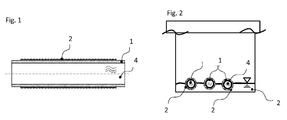
- FIG. 1 shows a line-shaped heat exchanger 1 with a cohesively surrounded this stainless steel powder coating.
- FIG. 2 shows in section this line-shaped heat exchanger 1 with a cohesively surrounded stainless steel powder coating 2 in the form of a semicircle in a container 5; this may be a module of an adsorption heat pump or a solar cooling system, in which there are no other gases or liquids apart from the refrigerant.
- a module of an adsorption heat pump with the line-shaped heat exchanger 1 according to the invention will be described. However, the invention is not limited to this application.
- the pipe-shaped heat exchanger 1 with the stainless steel powder coating 2 is disposed on the bottom of the container 5. On the bottom of the container 5 is also refrigerant 3 as the first fluid. A part of the line-shaped heat exchanger 1 is located in the liquid level of the refrigerant 3. Within the line-shaped heat exchanger 1, a second fluid 4 flows.
- the second fluid 4 flows through the line-shaped heat exchanger 1.
- the refrigerant 3 below the liquid level is pulled over the capillary action of the stainless steel powder coating 2 in the entire stainless steel powder coating 2 and heated there by the heat of the second fluid 4 and evaporated.
- the entire surface of the stainless steel powder coating 2 serves as Heat transfer surface. If refrigerant 3, which is located above the liquid level in the stainless steel powder coating 2, is evaporated, the stainless steel powder coating 2 dries therethrough; by the capillary effect refrigerant 3 flows from below into the stainless steel powder coating 2, so that the process can take place continuously.
- the stainless steel powder coating 2 is a powder with silicon carbide content.
- the line-shaped heat exchanger 1 is coated in this case by the thermal plasma spraying process.
- powder is supersonically injected into a high-temperature gas flame and melted or fused to the substrate during the flight phase.
- the powder drops burst into pancake-like structures.
- the coating has a surface enlarging effect.
- the porous structure allows a capillary effectiveness, so that in the present application, refrigerant 3 are pulled below the liquid level through the pores up and wet the entire line-shaped heat exchanger 1.
- the coating has increased chemical resistance, in particular corrosion resistance and an increase in the thermal conductivity result.
- lamellar tubes and corrugated tubes can also be easily coated in the thermal plasma spraying process.
- the tube may be round, oval, cross-sectioned, two parallel walls, or otherwise designed.
Landscapes
- Engineering & Computer Science (AREA)
- Physics & Mathematics (AREA)
- Thermal Sciences (AREA)
- Mechanical Engineering (AREA)
- General Engineering & Computer Science (AREA)
- Chemical & Material Sciences (AREA)
- Dispersion Chemistry (AREA)
- Heat-Exchange Devices With Radiators And Conduit Assemblies (AREA)
Abstract
Bei einem Leitungsförmiger Wärmetauscher (1), insbesondere Verdampfer-Wärmetauscher zum Verdampfen eines außerhalb des leitungsförmigen Wärmetauschers (1) befindlichen ersten Fluids (3) mittels eines in dem leitungsförmigen Wärmetauscher (1) strömenden zweiten Fluid (4), ist der leitungsförmige Wärmetauscher (1) von einer Pulverbeschichtung (2) umgeben.
Description
- Die Erfindung bezieht sich auf einen Wärmetauscher, insbesondere Verdampfer einer Adsorptionswärmepumpe oder thermischen Kühlung.
- Bei Adsorptionswärmepumpen befinden sich ein Adsorber/Desorber und ein Verdampfer-Kondensator-Wärmetauscher in einem abgeschlossenen Behälter. Ein Kältemittel wird im Adsorptionsprozess am Boden des Behälters mittels des Verdampfer-Wärmetauschers verdampft und vom Adsorber aufgenommen. In der Desorptionsphase agiert der Adsorber als Desorber. Das Kältemittel wird im Desorber desorbiert und kondensiert am Kondensator-Wärmetauscher, wodurch es sich unten im Behälter sammelt. Während des Verdampfungsprozesses muss der Verdampfer-Wärmetauscher in Kontakt mit dem Kältemittel treten.
- Bei bekannten derartigen Wärmetauschern liegt eine Rohrschlange auf deren Rippen auf dem Boden eines Vakuumbehälters auf. Dadurch ergibt sich jedoch der Nachteil nur sehr kleiner Auflageflächen der Rippen und damit bei gefluteter Komponente eine kleine Wärmetauschfläche für den Verdampfer und Kondensator, besonders bei geringer Kältemittelmenge.
- Aus
DE 10033972 B4 ist eine Variante bekannt, bei welcher die Rippen des Rippenrohres entlang einer Sehne abgeflacht sind und das Rippenrohr auf dieser Abflachung der Rippen auf der Platte aufliegt. Hierdurch kommt eine größere Rippenfläche bei geringem Füllstand in Berührung mit dem Kältemittel. - Nachteilig ist, dass die obere Hälfte des Verdampfers in der Regel nicht in Kontakt mit dem Kältemittel tritt und somit nur über Wärmeleitung zur Unterseite an der Verdampfung beteiligt ist. Der Verdampfer weist eine füllstandsabhängige Leistungscharakteristik auf.
- Ziel der Erfindung ist es, die Nachteile des Standes der Technik zu vermeiden und einen Wärmetauscher der eingangs erwähnten Art vorzuschlagen, bei dem für die Verdampfung eine große Fläche Wärme auf das Kältemittel übertragen kann.
- Erfindungsgemäß wird dies dadurch gelöst, dass ein leitungsförmiger Wärmetauscher von einer Pulverbeschichtung umgeben ist. Hierdurch vergrößert sich einerseits die Oberfläche. Andererseits wird hierdurch auch bei geringem Füllstand der gesamte überzogene Wärmetauscher mit zu verdampfendem Fluid benetzt, so dass sich die aktive Verdampferfläche erhöht.
- Vorteilhafte Ausgestaltungen ergeben sich durch die Merkmale der abhängigen Ansprüche.
- So hat sich neben einer Edelstahl-Beschichtung eine keramische Beschichtung mit Silizium-Carbid-Pulver als besonders vorteilhaft herausgestellt.
- Die Beschichtung kann nicht nur auf Glattrohren, sondern auch auf Lamellenrohre sowie Wellrohren angewendet werden.
- Die Erfindung wird nun anhand der Zeichnung näher erläutert. Dabei zeigen:
-
Fig. 1 einen erfindungsgemäßen Wärmetauscher sowie -
Fig. 2 einen erfindungsgemäßen Wärmetauscher in einem Behälter mit einem zu verdampfendem Fluid. -
Figur 1 zeigt einen leitungsförmigen Wärmetauscher 1 mit einer dieser stoffschlüssig umgebenen Edelstahl-Pulverbeschichtung 2.Figur 2 zeigt im Schnitt diesen leitungsförmigen Wärmetauscher 1 mit einer diesen stoffschlüssig umgebenen Edelstahl-Pulverbeschichtung 2 in Form eines Halbkreises in einem Behälter 5; hierbei kann es sich um ein Modul einer Adsorptionswärmepumpe oder einer solaren Kühlungsanlage handeln, in dem sich außer dem Kältemittel keine weiteren Gase oder Flüssigkeiten befinden. Im Folgenden wird ein Modul einer Adsorptionswärmepumpe mit dem erfindungsgemäßen leitungsförmigen Wärmetauscher 1 beschrieben. Die Erfindung beschränkt sich jedoch nicht auf diesen Anwendungsfall. - Der leitungsförmige Wärmetauscher 1 mit der Edelstahl-Pulverbeschichtung 2 ist auf dem Boden des Behälters 5 angeordnet. Auf dem Boden des Behälters 5 befindet sich ebenfalls Kältemittel 3 als erstes Fluid. Ein Teil des leitungsförmigen Wärmetauschers 1 befindet sich im Flüssigkeitsspiegel des Kältemittels 3. Innerhalb des leitungsförmigen Wärmetauschers 1 strömt ein zweites Fluid 4.
- In der Verdampfungsphase strömt das zweite Fluid 4 durch den leitungsförmigen Wärmetauscher 1. Das Kältemittel 3 unterhalb des Flüssigkeitsspiegels wird über die Kapillarwirkung der Edelstahl-Pulverbeschichtung 2 in die gesamte Edelstahl-Pulverbeschichtung 2 gezogen und dort von der Wärme des zweiten Fluids 4 erwärmt und verdampft. Hierbei dient die gesamte Oberfläche der Edelstahl-Pulverbeschichtung 2 als Wärmeübertrageroberfläche. Wird Kältemittel 3, das sich oberhalb des Flüssigkeitsspiegels in der Edelstahl-Pulverbeschichtung 2 befindet, verdampft, so trocknet die Edelstahl-Pulverbeschichtung 2 hierdurch; durch den Kapillareffekt strömt Kältemittel 3 von unten in die Edelstahl-Pulverbeschichtung 2 nach, so dass der Prozess kontinuierlich stattfinden kann.
- Bei der Edelstahl-Pulverbeschichtung 2 handelt es sich um ein Pulver mit Silizium-Carbid-Anteilen. Der leitungsförmige Wärmetauscher 1 wird hierbei im thermischen Plasmaspritzverfahren beschichtet. Hierzu wird Pulver mit Überschallgeschwindigkeit in eine Hochtemperatur-Gasflamme eingedüst und während der Flugphase bis zum Substrat aufgeschmolzen beziehungsweise angeschmolzen. Auf der Substratoberfläche zerspringen die Pulvertropfen zu pfannkuchenartigen Gebilden. Sie bilden in Abhängigkeit von der Pulvermenge (Schichtdicke) mehr oder weniger stark zerklüftete und poröse Schichten auf dem Substrat. Die Beschichtung hat einen oberflächenvergrößernden Effekt. Die poröse Struktur ermöglicht eine kapillare Wirksamkeit, so dass im vorliegenden Anwendungsfall Kältemittel 3 unterhalb des Flüssigkeitspegels durch die Poren nach oben gezogen werden und den gesamten leitungsförmigen Wärmetauscher 1 benetzen. Daneben hat die Beschichtung eine erhöhte chemische Beständigkeit, insbesondere Korrosionsbeständigkeit und eine Erhöhung der thermischen Leitfähigkeit zur Folge.
- Neben Glattrohren können auch Lamellenrohre und Wellrohre leicht im thermischen Plasmaspritzverfahren beschichtet werden. Das Rohr kann im Querschnitt rund, oval, mit zwei parallelen Wänden versehen oder auf eine andere Art gestaltet sein.
-
- 1
- leitungsförmiger Wärmetauscher
- 2
- Pulverbeschchtung
- 3
- Kältemittel / erstes Fluid
- 4
- zweite Fluid
- 5
- Behälter
Claims (4)
- Leitungsförmiger Wärmetauscher (1), insbesondere Verdampfer-Wärmetauscher zum Verdampfen eines außerhalb des leitungsförmigen Wärmetauschers (1) befindlichen ersten Fluids (3) mittels eines in dem leitungsförmigen Wärmetauscher (1) strömenden zweiten Fluid (4),
dadurch gekennzeichnet, dass der leitungsförmige Wärmetauscher (1) von einer Pulverbeschichtung (2) umgeben ist. - Leitungsförmiger Wärmetauscher (1) nach Anspruch 1, dadurch gekennzeichnet, dass die Pulverbeschichtung (2) eine Edelstahl-Beschichtung ist.
- Leitungsförmiger Wärmetauscher (1) nach Anspruch 2, dadurch gekennzeichnet, dass die Pulverbeschichtung (2) Silizium-Carbid-Pulver enthält.
- Leitungsförmiger Wärmetauscher (1) nach Anspruch 1 bis 3, dadurch gekennzeichnet, dass der leitungsförmige Wärmetauscher (1) über Lamellen verfügt oder ein Wellrohr ist.
Applications Claiming Priority (1)
| Application Number | Priority Date | Filing Date | Title |
|---|---|---|---|
| DE102014224137.5A DE102014224137A1 (de) | 2014-11-26 | 2014-11-26 | Verdampfer |
Publications (1)
| Publication Number | Publication Date |
|---|---|
| EP3026388A1 true EP3026388A1 (de) | 2016-06-01 |
Family
ID=54396781
Family Applications (1)
| Application Number | Title | Priority Date | Filing Date |
|---|---|---|---|
| EP15192792.8A Withdrawn EP3026388A1 (de) | 2014-11-26 | 2015-11-03 | Verdampfer |
Country Status (2)
| Country | Link |
|---|---|
| EP (1) | EP3026388A1 (de) |
| DE (1) | DE102014224137A1 (de) |
Citations (10)
| Publication number | Priority date | Publication date | Assignee | Title |
|---|---|---|---|---|
| GB2201764A (en) * | 1987-02-02 | 1988-09-07 | Mitsubishi Electric Corp | Heat exchanger tube for evaporation or condensation |
| JPH04148194A (ja) * | 1990-10-08 | 1992-05-21 | Daikin Ind Ltd | 吸着剤付き熱交換器 |
| JPH0961079A (ja) * | 1995-08-23 | 1997-03-07 | Hitachi Cable Ltd | 熱交換器及びその製造方法 |
| JPH10121110A (ja) * | 1996-10-15 | 1998-05-12 | Hitachi Chem Co Ltd | 沸騰伝熱部材及びその製造方法 |
| JPH10245602A (ja) * | 1997-03-03 | 1998-09-14 | Asahi Tec Corp | 多孔質体を有するパイプの製造方法 |
| DE29920530U1 (de) * | 1998-11-30 | 2000-01-13 | Joh. Vaillant Gmbh U. Co, 42859 Remscheid | Wärmetauscher |
| JP2001056195A (ja) * | 1999-08-12 | 2001-02-27 | Nkk Corp | 熱交換用伝熱管 |
| DE10202527A1 (de) * | 2002-01-24 | 2003-08-07 | Siegfried Lueck | Wärmetauschermodul für einen Rohrbündel-Wärmetauscher |
| US20080078532A1 (en) * | 2006-09-29 | 2008-04-03 | Denso Corporation | Adsorption module and method of manufacturing the same |
| DE10033972B4 (de) | 1999-07-07 | 2009-09-10 | Vaillant Gmbh | Wärmetauscher |
Family Cites Families (4)
| Publication number | Priority date | Publication date | Assignee | Title |
|---|---|---|---|---|
| DE102009053843A1 (de) * | 2009-11-18 | 2011-05-19 | Invensor Gmbh | Flächige Kältemittel-Zufuhr und -Verteilung für einen Wärmetauscher in Sorptionsmaschinen |
| WO2011162849A2 (en) * | 2010-04-01 | 2011-12-29 | The Board Of Regents Of The Nevada System Of Higher Education, On Behalf Of The University Of Nevada, Reno | Device having nano-coated porous integral fins |
| DE102011015153A1 (de) * | 2011-03-25 | 2012-09-27 | Sortech Ag | Verfahren und Vorrichtung zum Ausführen eines alternierenden Verdampfungs- und Kondensationsprozesses eines Arbeitsmediums |
| DE102013103840A1 (de) * | 2013-04-16 | 2014-10-16 | Benteler Automobiltechnik Gmbh | Verdampferrohr zur Anordnung in einem Abgasstrang sowie Verfahren zur Herstellung des Verdampferrohres mit poröser Sinterstruktur und Dampfkanälen |
-
2014
- 2014-11-26 DE DE102014224137.5A patent/DE102014224137A1/de not_active Withdrawn
-
2015
- 2015-11-03 EP EP15192792.8A patent/EP3026388A1/de not_active Withdrawn
Patent Citations (10)
| Publication number | Priority date | Publication date | Assignee | Title |
|---|---|---|---|---|
| GB2201764A (en) * | 1987-02-02 | 1988-09-07 | Mitsubishi Electric Corp | Heat exchanger tube for evaporation or condensation |
| JPH04148194A (ja) * | 1990-10-08 | 1992-05-21 | Daikin Ind Ltd | 吸着剤付き熱交換器 |
| JPH0961079A (ja) * | 1995-08-23 | 1997-03-07 | Hitachi Cable Ltd | 熱交換器及びその製造方法 |
| JPH10121110A (ja) * | 1996-10-15 | 1998-05-12 | Hitachi Chem Co Ltd | 沸騰伝熱部材及びその製造方法 |
| JPH10245602A (ja) * | 1997-03-03 | 1998-09-14 | Asahi Tec Corp | 多孔質体を有するパイプの製造方法 |
| DE29920530U1 (de) * | 1998-11-30 | 2000-01-13 | Joh. Vaillant Gmbh U. Co, 42859 Remscheid | Wärmetauscher |
| DE10033972B4 (de) | 1999-07-07 | 2009-09-10 | Vaillant Gmbh | Wärmetauscher |
| JP2001056195A (ja) * | 1999-08-12 | 2001-02-27 | Nkk Corp | 熱交換用伝熱管 |
| DE10202527A1 (de) * | 2002-01-24 | 2003-08-07 | Siegfried Lueck | Wärmetauschermodul für einen Rohrbündel-Wärmetauscher |
| US20080078532A1 (en) * | 2006-09-29 | 2008-04-03 | Denso Corporation | Adsorption module and method of manufacturing the same |
Also Published As
| Publication number | Publication date |
|---|---|
| DE102014224137A1 (de) | 2016-06-02 |
Similar Documents
| Publication | Publication Date | Title |
|---|---|---|
| DE102007026301A1 (de) | Abwärmerückgewinnungsvorrichtung | |
| EP3543626B1 (de) | Wasser-lithiumbromid-absorptionskälteanlage | |
| EP0733190B1 (de) | Kühlvorrichtung mit einer intermittierend arbeitenden kühleinheit | |
| DE202008007647U1 (de) | Heatpipe zur Wärmeübertragung in der Solarthermie | |
| DE10033972B4 (de) | Wärmetauscher | |
| DE2735593A1 (de) | Ventil fuer hochviskose medien fuehrende leitungen | |
| EP3021068A1 (de) | Verdampfer-wärmetauscher | |
| DE102008028854A1 (de) | Verdampfer und Kältemaschine oder Wärmepumpe | |
| DE2804411A1 (de) | Sonnenkollektor mit einem verdampfungs-kondensations-system | |
| DE102018212820A1 (de) | Sorptionswärmeübertragungsmodul | |
| DE102014224137A1 (de) | Verdampfer | |
| EP3124895A1 (de) | Adsorptionswärmepumpe mit plattenwärmetauscher | |
| WO2012052011A2 (de) | Kondensatrückführung in einer adsorptionskältemaschine | |
| EP2813782A1 (de) | Abschaltender Solarkollektor | |
| EP2677244B1 (de) | Luftbefeuchter | |
| EP2152634A1 (de) | Anlage und verfahren zur wasserreinigung mit hilfe eines sonnenkollektors | |
| DE10053045A1 (de) | Verfahren zur Herstellung eines Verdampfers/Kondensators | |
| DE102011105742A1 (de) | Periodisch arbeitende Sorptionsvorrichtung | |
| WO2005005011A1 (de) | Verdampfer-kondensator-wärmeübertrager | |
| DE102024123866A1 (de) | Fallfilmwärmeübertrager für Stoff- und Wärmeübertragung in Sorptionswärmepumpen und Sorptionswärmepumpe bzw. -kältemaschine hiermit | |
| WO2012000494A2 (de) | Selbststabilisierende trennwand mit erhöhter thermischer isolation für unterdruckbehälter | |
| DE102016123512A1 (de) | Verdampfervorrichtung | |
| DE102017202871B4 (de) | Wärmetauschersystem zum Übertragen der Abgaswärme einer Brennkraftmaschine | |
| DE102013109048A1 (de) | Verfahren und Vorrichtung zur Kühlung von Strahlungsquellen auf Basis eines Plasmas | |
| DE476256C (de) | Absorptionskaeltemaschine |
Legal Events
| Date | Code | Title | Description |
|---|---|---|---|
| PUAI | Public reference made under article 153(3) epc to a published international application that has entered the european phase |
Free format text: ORIGINAL CODE: 0009012 |
|
| AK | Designated contracting states |
Kind code of ref document: A1 Designated state(s): AL AT BE BG CH CY CZ DE DK EE ES FI FR GB GR HR HU IE IS IT LI LT LU LV MC MK MT NL NO PL PT RO RS SE SI SK SM TR |
|
| AX | Request for extension of the european patent |
Extension state: BA ME |
|
| STAA | Information on the status of an ep patent application or granted ep patent |
Free format text: STATUS: THE APPLICATION IS DEEMED TO BE WITHDRAWN |
|
| 18D | Application deemed to be withdrawn |
Effective date: 20161202 |