EP3025990A1 - Paper feeding device - Google Patents
Paper feeding device Download PDFInfo
- Publication number
- EP3025990A1 EP3025990A1 EP15194695.1A EP15194695A EP3025990A1 EP 3025990 A1 EP3025990 A1 EP 3025990A1 EP 15194695 A EP15194695 A EP 15194695A EP 3025990 A1 EP3025990 A1 EP 3025990A1
- Authority
- EP
- European Patent Office
- Prior art keywords
- paper feeding
- sheet
- roller
- braking
- paper
- Prior art date
- Legal status (The legal status is an assumption and is not a legal conclusion. Google has not performed a legal analysis and makes no representation as to the accuracy of the status listed.)
- Granted
Links
- 238000001514 detection method Methods 0.000 claims abstract description 13
- 238000010586 diagram Methods 0.000 description 15
- 238000000034 method Methods 0.000 description 9
- 239000000976 ink Substances 0.000 description 2
- 238000011144 upstream manufacturing Methods 0.000 description 2
- 230000001133 acceleration Effects 0.000 description 1
- 230000005540 biological transmission Effects 0.000 description 1
- 230000007423 decrease Effects 0.000 description 1
- 230000003287 optical effect Effects 0.000 description 1
Images


Classifications
-
- B—PERFORMING OPERATIONS; TRANSPORTING
- B65—CONVEYING; PACKING; STORING; HANDLING THIN OR FILAMENTARY MATERIAL
- B65H—HANDLING THIN OR FILAMENTARY MATERIAL, e.g. SHEETS, WEBS, CABLES
- B65H3/00—Separating articles from piles
- B65H3/02—Separating articles from piles using friction forces between articles and separator
- B65H3/06—Rollers or like rotary separators
- B65H3/0669—Driving devices therefor
-
- B—PERFORMING OPERATIONS; TRANSPORTING
- B65—CONVEYING; PACKING; STORING; HANDLING THIN OR FILAMENTARY MATERIAL
- B65H—HANDLING THIN OR FILAMENTARY MATERIAL, e.g. SHEETS, WEBS, CABLES
- B65H5/00—Feeding articles separated from piles; Feeding articles to machines
- B65H5/06—Feeding articles separated from piles; Feeding articles to machines by rollers or balls, e.g. between rollers
-
- B—PERFORMING OPERATIONS; TRANSPORTING
- B41—PRINTING; LINING MACHINES; TYPEWRITERS; STAMPS
- B41J—TYPEWRITERS; SELECTIVE PRINTING MECHANISMS, i.e. MECHANISMS PRINTING OTHERWISE THAN FROM A FORME; CORRECTION OF TYPOGRAPHICAL ERRORS
- B41J13/00—Devices or arrangements of selective printing mechanisms, e.g. ink-jet printers or thermal printers, specially adapted for supporting or handling copy material in short lengths, e.g. sheets
- B41J13/02—Rollers
- B41J13/076—Construction of rollers; Bearings therefor
-
- B—PERFORMING OPERATIONS; TRANSPORTING
- B65—CONVEYING; PACKING; STORING; HANDLING THIN OR FILAMENTARY MATERIAL
- B65H—HANDLING THIN OR FILAMENTARY MATERIAL, e.g. SHEETS, WEBS, CABLES
- B65H3/00—Separating articles from piles
- B65H3/02—Separating articles from piles using friction forces between articles and separator
- B65H3/06—Rollers or like rotary separators
- B65H3/0638—Construction of the rollers or like rotary separators
-
- B—PERFORMING OPERATIONS; TRANSPORTING
- B65—CONVEYING; PACKING; STORING; HANDLING THIN OR FILAMENTARY MATERIAL
- B65H—HANDLING THIN OR FILAMENTARY MATERIAL, e.g. SHEETS, WEBS, CABLES
- B65H5/00—Feeding articles separated from piles; Feeding articles to machines
- B65H5/06—Feeding articles separated from piles; Feeding articles to machines by rollers or balls, e.g. between rollers
- B65H5/062—Feeding articles separated from piles; Feeding articles to machines by rollers or balls, e.g. between rollers between rollers or balls
-
- B—PERFORMING OPERATIONS; TRANSPORTING
- B65—CONVEYING; PACKING; STORING; HANDLING THIN OR FILAMENTARY MATERIAL
- B65H—HANDLING THIN OR FILAMENTARY MATERIAL, e.g. SHEETS, WEBS, CABLES
- B65H7/00—Controlling article feeding, separating, pile-advancing, or associated apparatus, to take account of incorrect feeding, absence of articles, or presence of faulty articles
- B65H7/02—Controlling article feeding, separating, pile-advancing, or associated apparatus, to take account of incorrect feeding, absence of articles, or presence of faulty articles by feelers or detectors
-
- B—PERFORMING OPERATIONS; TRANSPORTING
- B65—CONVEYING; PACKING; STORING; HANDLING THIN OR FILAMENTARY MATERIAL
- B65H—HANDLING THIN OR FILAMENTARY MATERIAL, e.g. SHEETS, WEBS, CABLES
- B65H7/00—Controlling article feeding, separating, pile-advancing, or associated apparatus, to take account of incorrect feeding, absence of articles, or presence of faulty articles
- B65H7/18—Modifying or stopping actuation of separators
-
- B—PERFORMING OPERATIONS; TRANSPORTING
- B65—CONVEYING; PACKING; STORING; HANDLING THIN OR FILAMENTARY MATERIAL
- B65H—HANDLING THIN OR FILAMENTARY MATERIAL, e.g. SHEETS, WEBS, CABLES
- B65H7/00—Controlling article feeding, separating, pile-advancing, or associated apparatus, to take account of incorrect feeding, absence of articles, or presence of faulty articles
- B65H7/20—Controlling associated apparatus
-
- B—PERFORMING OPERATIONS; TRANSPORTING
- B65—CONVEYING; PACKING; STORING; HANDLING THIN OR FILAMENTARY MATERIAL
- B65H—HANDLING THIN OR FILAMENTARY MATERIAL, e.g. SHEETS, WEBS, CABLES
- B65H2403/00—Power transmission; Driving means
-
- B—PERFORMING OPERATIONS; TRANSPORTING
- B65—CONVEYING; PACKING; STORING; HANDLING THIN OR FILAMENTARY MATERIAL
- B65H—HANDLING THIN OR FILAMENTARY MATERIAL, e.g. SHEETS, WEBS, CABLES
- B65H2403/00—Power transmission; Driving means
- B65H2403/70—Clutches; Couplings
- B65H2403/72—Clutches, brakes, e.g. one-way clutch +F204
- B65H2403/725—Brakes
-
- B—PERFORMING OPERATIONS; TRANSPORTING
- B65—CONVEYING; PACKING; STORING; HANDLING THIN OR FILAMENTARY MATERIAL
- B65H—HANDLING THIN OR FILAMENTARY MATERIAL, e.g. SHEETS, WEBS, CABLES
- B65H2404/00—Parts for transporting or guiding the handled material
- B65H2404/10—Rollers
- B65H2404/14—Roller pairs
-
- B—PERFORMING OPERATIONS; TRANSPORTING
- B65—CONVEYING; PACKING; STORING; HANDLING THIN OR FILAMENTARY MATERIAL
- B65H—HANDLING THIN OR FILAMENTARY MATERIAL, e.g. SHEETS, WEBS, CABLES
- B65H2511/00—Dimensions; Position; Numbers; Identification; Occurrences
- B65H2511/10—Size; Dimensions
- B65H2511/11—Length
-
- B—PERFORMING OPERATIONS; TRANSPORTING
- B65—CONVEYING; PACKING; STORING; HANDLING THIN OR FILAMENTARY MATERIAL
- B65H—HANDLING THIN OR FILAMENTARY MATERIAL, e.g. SHEETS, WEBS, CABLES
- B65H2511/00—Dimensions; Position; Numbers; Identification; Occurrences
- B65H2511/40—Identification
- B65H2511/416—Identification of material
-
- B—PERFORMING OPERATIONS; TRANSPORTING
- B65—CONVEYING; PACKING; STORING; HANDLING THIN OR FILAMENTARY MATERIAL
- B65H—HANDLING THIN OR FILAMENTARY MATERIAL, e.g. SHEETS, WEBS, CABLES
- B65H2511/00—Dimensions; Position; Numbers; Identification; Occurrences
- B65H2511/50—Occurence
- B65H2511/51—Presence
- B65H2511/514—Particular portion of element
-
- B—PERFORMING OPERATIONS; TRANSPORTING
- B65—CONVEYING; PACKING; STORING; HANDLING THIN OR FILAMENTARY MATERIAL
- B65H—HANDLING THIN OR FILAMENTARY MATERIAL, e.g. SHEETS, WEBS, CABLES
- B65H2513/00—Dynamic entities; Timing aspects
- B65H2513/20—Acceleration or deceleration
-
- B—PERFORMING OPERATIONS; TRANSPORTING
- B65—CONVEYING; PACKING; STORING; HANDLING THIN OR FILAMENTARY MATERIAL
- B65H—HANDLING THIN OR FILAMENTARY MATERIAL, e.g. SHEETS, WEBS, CABLES
- B65H2513/00—Dynamic entities; Timing aspects
- B65H2513/50—Timing
- B65H2513/512—Starting; Stopping
-
- B—PERFORMING OPERATIONS; TRANSPORTING
- B65—CONVEYING; PACKING; STORING; HANDLING THIN OR FILAMENTARY MATERIAL
- B65H—HANDLING THIN OR FILAMENTARY MATERIAL, e.g. SHEETS, WEBS, CABLES
- B65H2515/00—Physical entities not provided for in groups B65H2511/00 or B65H2513/00
- B65H2515/10—Mass, e.g. mass flow rate; Weight; Inertia
-
- B—PERFORMING OPERATIONS; TRANSPORTING
- B65—CONVEYING; PACKING; STORING; HANDLING THIN OR FILAMENTARY MATERIAL
- B65H—HANDLING THIN OR FILAMENTARY MATERIAL, e.g. SHEETS, WEBS, CABLES
- B65H2701/00—Handled material; Storage means
- B65H2701/10—Handled articles or webs
- B65H2701/13—Parts concerned of the handled material
- B65H2701/131—Edges
- B65H2701/1311—Edges leading edge
Definitions
- the present invention relates to a paper feeding device configured to feed sheets.
- a printer such as an inkjet printer or a stencil printer includes a paper feeding device configured to send out sheets from a paper feed tray and convey the sheets to a printing unit.
- a paper feeding roller sends out each sheet one by one on the paper feed tray to an intermediate conveying roller, and the intermediate conveying roller sends out the sheet to a registration roller. A leading edge of the sent-out sheet abuts on the registration roller and temporarily stops.
- the intermediate roller continues to send out the sheet toward the registration roller after the leading edge of the sheet stops. Accordingly, the sheet forms sag between the registration roller and the intermediate conveying roller until the registration roller starts to rotate. This sag corrects skewing of the sheet and the sheet whose skewing is corrected is sent out to the printing unit with the rotation start of the registration roller.
- a motor driving the paper feeding roller is stopped by deceleration control after the leading edge of the sheet reaches the intermediate conveying roller.
- the motor is connected to the paper feeding roller via a one-way clutch, and the paper feeding roller is rotated by following the sheet after the motor stops. The following rotation of the paper feeding roller continues until a trailing edge of the sheet passes the paper feeding roller.
- Stopping the motor for the paper feeding roller by the deceleration control requires a certain amount of time. Accordingly, when the trailing edge of the sheet passes the paper feeding roller before the motor stops, the paper feeding roller ends the following rotation, but continues to rotate for a while by the drive of the motor and sends out the subsequent sheet in the paper feed tray slightly. Due to this, the subsequent sheet is sent out from the paper feed tray sometimes at incorrect timing.
- Japanese Unexamined Patent Application Publication 2009-40568 propose a technique of sending out a sheet to a printing unit at correct timing.
- this technique when a sensor arranged between a paper feeding roller and a registration roller detects a leading edge of the sheet, the speed of a conveying roller conveying the sheet is reduced from a first speed to a second speed.
- the second speed is set higher as the timing at which the sensor detects the leading edge of the sheet becomes later.
- An object of the present invention is to provide a paper feeding device capable of suppressing a position shift of a subsequent sheet in a paper feed tray in the process of stopping a paper feed motor rotating a paper feeding roller.
- a paper feeding device in accordance with some embodiments includes: a paper feeding roller configured to rotate at a predetermined speed and send out sheets one by one from a paper feed tray on which the sheets are stacked to a sheet conveying route located downstream of the paper feed tray in a sheet conveying direction; a paper feeding motor configured to perform a rotating operation of rotating the paper feeding roller and maintain a rotational speed of the paper feeding roller at the predetermined speed; an intermediate conveying roller arranged downstream of the paper feeding roller in the sheet conveying direction in the sheet conveying route and configured to send out each of the sheets sent out by the paper feeding roller to a position located downstream of the intermediate conveying roller in the sheet conveying direction in the sheet conveying route; a sheet sensor configured to detect the sheet having a leading edge reaching the intermediate conveying roller; a braking content determiner configured to determine a content of braking control on the rotating operation such that rotation of the paper feeding motor stops within a time required for stopping from a time point of detection of the sheet by the sheet sensor to a time point of passing of a trail
- the configuration described above can suppress a position shift of a subsequent sheet in the paper feed tray in the process of stopping the paper feed motor rotating the paper feeding roller.
- the rotating operation of the paper feeding motor for rotating the paper feeding roller can be stopped at this point.
- the paper feeding roller and the paper feeding motor rotate by inertia.
- the paper feeding roller follows the sheet conveyed by the intermediate roller and is rotated by the sheet until the trailing edge of the sheet passes the paper feeding roller.
- the paper feeding roller is not rotated by the paper feeding motor after the passing of the trailing edge of the sheet.
- time point at which the trailing edge of the sheet passes the paper feeding roller is set as target timing for stopping the rotation of the paper feeding motor by inertia and use a period from the detection of the sheet by the sheet sensor to this time point as an indication of time usable for stopping the rotating operation of the paper feeding motor.
- time point and period can be used as time elements of the rotating operation of the paper feeding motor and the rotation of the paper feeding roller in the case of determining the content of the braking control on the rotating operation of the paper feeding motor.
- the length of the sheet in the sheet conveying direction, the predetermined speed which is the rotational speed of the paper feeding roller in the sending out of the sheet, and the distance between the paper feeding roller and the sheet sensor are all known and can be used as distance elements of relative positions of the paper feeding roller and the sheet in the case of determining the content of the braking control on the rotating operation of the paper feeding motor.
- the content of braking control performed on the rotating operation of the paper feeding motor such that the rotation of the paper feeding motor by inertia stops in accordance with the timing of the trailing edge of the sheet passing the paper feeding roller can be determined based on the time elements of the rotating operation of the paper feeding motor and the rotation of the paper feeding roller and the distance elements of the relative positions of the paper feeding roller and the sheet which are obtained as described above.
- the braking content determiner may determine deceleration control on the rotating operation of the paper feeding motor at a degree of deceleration as the content of the braking control.
- the configuration described above can brake the paper feeding motor to stop the paper feeding motor in accordance with the timing of the trailing edge of the sheet passing the paper feeding roller, by using the braking control according to the determined content.
- the braking content determiner may determine that the content of the braking control includes a start timing of deceleration control on the rotating operation of the paper feeding motor at a degree of deceleration due to inertia.
- the configuration described above can brake the paper feeding motor to stop the paper feeding motor in accordance with the timing of the trailing edge of the sheet passing the paper feeding roller, by using the braking control according to the determined content.
- the braking content determiner may determine the content of the braking control from inertia of the paper feeding roller depending on a paper type of the sheet.
- the configuration described above can brake the paper feeding motor to stop the paper feeding motor in accordance with the timing of the trailing edge of the sheet passing the paper feeding roller, by performing the braking control according to the content corresponding to the paper type of each sheet.
- the braking content determiner may determine a time point of the detection of the sheet by the sheet sensor as a start timing of the deceleration control.
- the braking content determiner may determine a time point prior to the detection of the sheet by the sheet sensor as the start timing of the deceleration control.
- the braking content determiner may determine that the content of the braking control includes deceleration control on the rotating operation of the paper feeding motor at a degree of deceleration and a start timing of the deceleration control.
- the paper feeding motor is connected to the paper feeding roller via a one-way clutch.
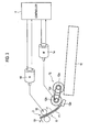
- Fig. 1 is an explanatory diagram illustrating a schematic configuration of a printer including a paper feeding device in one embodiment of the present invention.
- Fig. 2 is a block diagram illustrating a configuration of a control system of the printer illustrated in Fig. 1 .
- directions orthogonal to the sheet surface of Fig. 1 are referred to as front-rear directions, and a direction toward the front side of the sheet is referred to as front.
- directions of right, left, up, and down are denoted by RT, LT, UP, and DN, respectively.
- a route illustrated by a bold line in Fig. 1 is a sheet conveying route R through which sheets P being print media are conveyed.
- upstream and downstream mean upstream and downstream in the sheet conveying route R.
- the printer 1 includes a paper feeder 2 and a printing unit 3. Moreover, as illustrated in Fig. 2 , the printer 1 further includes a controller 4 configured to control operations of the paper feeder 2 and the printing unit 3. Note that the paper feeding device of the embodiment includes the controller 4 used in common with the printer 1 and the paper feeder 2 of the printer 1.
- the paper feeder 2 feeds the sheets P to the printing unit 3.
- the paper feeder 2 includes a paper feed tray 11, paper feeding rollers 12, intermediate conveying rollers 15, registration rollers 17, and a sheet sensor 19.
- the paper feeder 2 further includes a paper feeding motor 14, an intermediate conveying motor 16, and a registration motor 18.
- the paper feed tray 11 illustrated in Fig. 1 is a tray on which the sheets P used for printing are stacked, and the paper feeding rollers 12 are arranged above the paper feed tray 11.
- Fig. 3 is an explanatory diagram illustrating a schematic configuration of the paper feeding rollers 12.
- the paper feeding rollers 12 include a scraper roller 12a and a pickup roller 12b.
- the scraper roller 12a is in contact with the top sheet P out of the sheets P stacked on the paper feed tray 11 and sends out the top sheet P from the paper feed tray 11 by being rotated.
- the pickup roller 12b picks up each sheet P, sent out from the paper feed tray 11 by the scraper roller 12a, one by one together with a friction pad 12c and sends out the sheet P to a space between a pair of sheet conveying guides r1 in the sheet conveying route R.
- the paper feeding motor 14 rotates the paper feeding rollers 12. Specifically, the paper feeding motor 14 synchronously rotates the scraper roller 12a and the pickup roller 12b having shafts around which a timing belt 12b is wound.
- the paper feeding motor 14 is connected to the scraper roller 12a and the pickup roller 12b via a not-illustrated one-way clutch. This one-way clutch transmits only the rotation in a direction in which the sheet P is sent out toward the sheet conveying route R, from the paper feeding motor 14 to the scraper roller 12a and the pickup roller 12b
- the pair of intermediate conveying rollers 15 are arranged downstream of the pickup roller 12b along the sheet conveying guides r1 of the sheet conveying route R.
- the intermediate conveying rollers 15 nip a leading edge of the sheet P being sent out from the paper feed tray 11 to the sheet conveying route R by the paper feeding rollers 12 (scraper roller 12a and pickup roller 12b), and send out the sheet P to the registration rollers 17 downstream in the sheet conveying route R.
- the intermediate conveying motor 16 drives one of the intermediate conveying rollers 15.
- the paper feeder 2 has one paper feed tray 11 and, in accordance with this, is provided with one set of paper feeding rollers 12 and one set of intermediate conveying rollers 15 as illustrated in Fig. 1 .
- the present invention can be applied to a case where multiple sets of paper feeding trays 11, paper feeding rollers 12, and intermediate conveying rollers 15 are provided.
- the registration rollers 17 are arranged downstream of the intermediate conveying rollers 15.
- the registration rollers 17 temporarily stop the sheet P conveyed by the intermediate conveying rollers 15 and convey the sheet P to the printing unit 3 after sag is formed in the sheet P.
- the registration motor 18 drives the registration rollers 17.
- the sheet sensor 19 detects the sheet P at a detecting position D downstream of the intermediate conveying rollers 15 and outputs a detection signal to the controller 4.
- the sheet sensor 19 is formed of an optical sensor having a light emitting element and a light receiving element.
- the printing unit 3 prints the fed sheet P while conveying the sheet P.
- the printing unit 3 is arranged downstream of the paper feeder 2.
- the printing unit 3 includes a belt conveyer 21 and an inkjet head unit 22.
- the belt conveyer 21 conveys the sheet P conveyed by the registration rollers 17 while sucking and holding the sheet P on a belt. Rollers around which the belt of the belt conveyer 21 is wound are driven by a not-illustrate motor. This causes the belt to rotate and the sheet P on the belt is conveyed.
- the inkjet head unit 22 is arranged above the belt conveyer 21.
- the inkjet head unit 22 has multiple line-type inkjet heads in each of which multiple nozzles are arranged in a direction substantially orthogonal to the conveying direction of the sheet P (front-rear directions).
- the inkjet head unit 22 prints an image by ejecting inks from the inkjet heads onto the sheet P conveyed by the belt conveyer 21.
- the controller 4 controls operations of the units in the printer 1.
- the controller 4 includes a CPU, a RAM, a ROM, a hard disk drive, and the like.
- the controller 4 performs control such that the paper feeder 2 feeds the sheet P to the printing unit 3 and, in the printing unit 3, the inkjet head unit 22 prints the sheet P by ejecting inks while the sheet P is conveyed by the belt conveyer 21.
- the controller 4 stops the intermediate conveying rollers 15 when the sheet P conveyed by the intermediate conveying rollers 15 abuts on the registration rollers 17 and sag of a specified amount L is formed in the sheet P. After stopping the intermediate conveying rollers 15, the controller 4 starts the drive of the registration rollers 17.
- controller 4 controls the drive of the paper feeding motor 14, based on the detection of the sheet P by the sheet sensor 19.
- Fig. 4 is an explanatory diagram illustrating an overview of the drive control of the paper feeding motor 14 which the controller 4 can perform.
- the controller 4 causes the paper feeder 2 to feed the sheet P from the paper feed tray 11 to the printing unit 3.
- the controller 4 first drives the paper feeding motor 14 to rotate the paper feeding rollers 12 (scraper roller 12a and pickup roller 12b) in the direction in which the sheet P is sent out from the paper feed tray 11.
- section (A) a section from timing ts to timing t1 is referred to as section (A)
- a section from the timing t1 to timing t3 is referred to as section (B)
- a section from the timing t3 to timing t5 is referred to as section (C)
- a section after the timing t5 is referred to as section (D).
- Fig. 4 is provided to facilitate the understanding of braking control of the paper feeding motor 14 in the embodiment described below and does not explain the braking control of the paper feeding motor 14 in the embodiment.
- the drive of the paper feeding motor 14 starts at the timing ts, and the paper feeding motor 14 is made to accelerate until the rotational speed of the paper feeding rollers 12 (scraper roller 12a and pickup roller 12b) reaches a predetermined speed corresponding to a conveying speed of the sheet P.
- the paper feeding rollers 12 are driven and rotated by the paper feeding motor 14.
- the leading edge of the sheet P sent out by the paper feeding rollers 12 reaches the intermediate conveying rollers 15 and is nipped while the control of the section (A) is performed.
- the controller 4 drives the intermediate conveying motor 16 such that the intermediate conveying rollers 15 convey the sheet P at the same conveying speed as that of the paper feeding rollers 12. Accordingly, the sheet P nipped by the intermediate conveying rollers 15 and being sent out by the paper feeding rollers 12 is conveyed toward the registration rollers 17 by the intermediate conveying rollers 15 at the same speed.
- the controller 4 starts the deceleration control for stopping the rotation of the paper feeding motor 14 at, for example, the timing t1 of the sheet sensor 19 detecting the leading edge of the sheet P passing the intermediate conveying rollers 15.
- the deceleration control of the paper feeding motor 14 is performed by reducing the speed of the rotation of the paper feeding motor 14 at a predetermined degree of deceleration (for example, a degree of deceleration due to inertia).
- the paper feeding rollers 12 follow the sheet P conveyed toward the registration rollers 17 by the intermediate conveying rollers 15, and are rotated at the same speed as in the section (A).
- the rotational speed of the paper feeding motor 14 gradually decreases after the timing t1 due to the deceleration control by the controller 4, and the paper feeding motor 14 eventually stops.
- the time required until the paper feeding motor 14 stops is long and, as illustrated in the section (C) of Fig. 4 , the rotation the paper feeding motor 14 stops long after the timing t3 of the trailing edge of the sheet P passing the pickup roller 12b.
- the paper feeding rollers 12 are thus rotated by the paper feeding motor 14 until the rotation of the paper feeding motor 14 stops, after the timing t4 at which the rotation of the paper feeding rollers 12 by inertia should stop after the trailing edge of the sheet P passes the pickup roller 12b of the paper feeding rollers 12. Then, after the timing t5 of stop of the rotation of the paper feeding motor 14, i.e. in the section (D) of Fig. 4 , the rotation of the paper feeding rollers 12 stops at last.
- the subsequent sheet P in the paper feed tray 11 is sent out by the rotation of the paper feeding rollers 12 (scraper roller 12a and pickup roller 12b) in the section (C) in which the paper feeding motor 14 under the deceleration control rotates the paper feeding rollers 12 by inertia, after the timing t4 at which the rotation of the paper feeding rollers 12 by inertia should stop after the trailing edge of the sheet P sent out from the paper feed tray 11 passes the pickup roller 12b.
- the subsequent sheet P is sent out from the paper feed tray 11 to the space between the sheet conveying guides r1 of the sheet conveying route R by the paper feeding rollers 12 (scraper roller 12a and pickup roller 12b).
- the position of the leading edge Pt of the subsequent sheet P is thereby shifted from an original position in the paper feed tray 11 toward the intermediate conveying rollers 15.
- the paper feeding motor 14 rotates at a rotational speed Vj by inertia in a period from the timing t3 of the trailing edge of the sheet P passing the pickup roller 12b to the timing t5 of stop of the rotation of the paper feeding motor 14 by inertia and stop of the rotation of the paper feeding rollers 12 (scraper roller 12a and the pickup roller 12b) due to the rotation of the paper feeding motor 14.
- the controller 4 performs the deceleration control of the paper feeding motor 14 (braking control on the rotating operation of the paper feeding motor 14) such that the rotation of the paper feeding motor 14 stops before the rotation of the paper feeding rollers 12 following the sheet P stops with the passing of the sheet P.
- the deceleration control of the paper feeding motor 14 performed by the controller 4 includes two general patterns (content of the braking control on the rotating operation of the paper feeding motor 14 which stops the rotation of the paper feeding motor 14 before the trailing edge of the sheet P passes the paper feeding rollers 12).
- the first pattern is a pattern of changing the degree of deceleration of the paper feeding motor 14 from that in the deceleration control pattern of the example described above, without changing the start timing of the deceleration control.
- the second pattern is a pattern of changing the start timing of deceleration control from that in the deceleration control pattern of the example described above, without changing the degree of deceleration of the paper feeding motor 14.
- the deceleration control in each of the patterns is described below with reference to the explanatory diagram of Fig.
- the controller 4 functions as a braking content determiner configured to determine the content of the braking control, and performs the braking control according to the determined content.
- the determination of the content of the braking control and the braking control according to the determined content are performed by the controller 4.
- the controller 4 first starts the deceleration control of the paper feeding motor 14 at the timing t1 of the sheet sensor 19 detecting the leading edge of the sheet P passing the intermediate conveying rollers 15. In this case, the degree of deceleration of the paper feeding motor 14 is changed to a degree of deceleration (1) which is greater than the degree of deceleration in the example described above.
- the deceleration control of the paper feeding motor 14 is performed at the predetermined degree of deceleration in the example described above, starting from the timing t1 of the sheet sensor 19 detecting the leading edge of the sheet P passing the intermediate conveying rollers 15.
- the rotation of the paper feeding motor 14 stops at the timing t5 which is later than the timing t4 at which the rotation of the paper feeding rollers 12 by inertia after the passing of the trailing edge of the sheet P sent out from the paper feed tray 11 should stop.
- the rotation of the paper feeding motor 14 is stopped by the timing t3 of the trailing edge of the sheet P passing the pickup roller 12b.
- the paper feeding motor 14 thereby stops by the timing t4 of stop of the rotation of the paper feeding rollers 12 by inertia, the paper feeding rollers 12 no longer being rotated by the sheet P due to passing of the sheet P.
- the degree of deceleration (1) can be obtained by dividing a conveying speed v (predetermined speed) (a speed in a horizontal section of a graph of the scraper roller speed in Fig. 6 ) of the sheet P at the time when the rotational speed of the scraper roller 12a, the pickup roller 12b, and the intermediate conveying rollers 15 becomes constant after the start of rotation and acceleration, by the time t required for stopping (1) in the deceleration control at the degree of deceleration (1).
- v predetermined speed
- the time t required for stopping (1) can be obtained by dividing the difference (p-a) between the total length of the sheet P and the distance a from the scraper roller 12a to the detecting position D where the sheet sensor 19 is installed, by the conveying speed v of the sheet P.
- the time t required for stopping (1) may be obtained in consideration of this.
- the rotation of the paper feeding motor 14 is stopped before the send-out amount dj of the sheet P in the period (t5-t3) from the time point when the sheet P passes the pickup roller 12b to the time point when the rotation of the paper feeding motor 14 by inertia stops reaches a distance x which is the maximum value of the allowable range for the position shift of the sheet P from the normal position.
- the aforementioned distance x is reflected in a formula for obtaining the time t required for stopping (1).
- the time t required for stopping (1) is obtained by setting a term of a numerator in this formula to (p-a+x) and dividing this term by the conveying speed v of the sheet P.
- the degree of deceleration (1) needs to be set within a range of a braking torque Q which can be applied to the paper feeding motor 14.
- the braking torque Q of the paper feeding motor 14 can be obtained by multiplying the inertia J of the paper feeding rollers 12 (scraper roller 12a and pickup roller 12b) by the degree of deceleration (1). Accordingly, the value of the degree of deceleration (1) is set such that a value Q1 of the thus-obtained braking torque Q falls within the allowable range.
- the controller 4 does not change the degree of deceleration of the paper feeding motor 14 from a degree of deceleration (2) which is the same as the degree of deceleration in the example described above. Instead, the controller 4 changes the start timing of the deceleration control to timing t0 which is earlier than the timing t1 of the sheet sensor 19 detecting the leading edge of the sheet P passing the intermediate conveying rollers 15.
- the timing t0 may be timing at which the leading edge of the sheet P reaches or has already reached the intermediate conveying rollers 15 or timing at which the leading edge of the sheet P has not reached the intermediate conveying rollers 15 yet. Note that the latter timing is such timing that the leading edge of the sheet P can reach the intermediate conveying rollers 15 by the rotation of the paper feeding motor 14 and the paper feeding rollers 12 by inertia after the start of the deceleration control, before the rotation of the paper feeding rollers 12 stops.
- the time t required for stopping (2) can be obtained by dividing the conveying speed v (scraper roller speed) of the sheet P by the intermediate conveying rollers 15, by the degree of deceleration (2). Moreover, a distance L by which the sheet P is conveyed in the deceleration control at the degree of deceleration (2) in the time t required for stopping (2) can be obtained by multiplying the degree of deceleration (2) by the square of the time t required for stopping (2).
- the start timing t0 of the deceleration control is thus timing at which the trailing edge Pe of the sheet P is located behind (on the paper feed tray 11 side of) the scraper roller 12a by the distance L.
- the leading edge Pt of the sheet P at this timing is located behind (on the paper feed tray 11 side of) the detecting position D of the sheet sensor 19 by a distance equal to the difference (L-(p-a)) between the distance L and the difference (p-a) between the total length p of the sheet P and the distance a from the scraper roller 12a to the detecting position D where the sheet sensor 19 is installed.
- this position can be defined based on the total length p of the sheet P and the distance a from the scraper roller 12a to the detecting position D where the sheet sensor 19 is installed.
- the degree of deceleration (1) which is determined in the first pattern and the time t required for stopping (2) and the start timing t0 of the deceleration control based thereon which are determined in the second pattern (2) can be determined based on the total length p of the sheet P and the distance a from the scraper roller 12a to the detecting position D where the sheet sensor 19 is installed.
- a rotation torque Qj of the paper feeding rollers 12 rotated by the paper feeding motor 14 rotating by inertia after the start of the deceleration control is equal to a value obtained by multiplying a degree of deceleration ⁇ j of the paper feeding motor 14 at this time by the inertia J of the paper feeding rollers 12.
- the rotation torque Qj is equal to or greater than a friction force To acting between the sheet P and the paper feeding rollers 12, the sheet P is sent out by the paper feeding rollers 12 rotated by the paper feeding motor 14 rotating by inertia.
- the degree of deceleration ⁇ j of the paper feeding motor 14 rotating by inertia can be expressed by Vj/(t5-3), where the rotational speed Vj of the paper feeding motor 14 by inertia is divided by the period (t5-t3) of rotation of the paper feeding motor 14 by inertia.
- the friction force To acting between the paper feeding rollers 12 and the sheet P varies depending on the paper type (for example, normal paper, mat paper, and the like). This is because the coefficient of friction of the sheet P varies depending on the paper type. Accordingly, there is a case where the sheet P of paper type with a small coefficient of friction is sent out from the paper feed tray 11 but the sheet P of paper type with a large coefficient of friction is not sent out from the paper feed tray 11 when the paper feeding rollers 12 rotate at the same rotation torque Q1.
- the controller 4 may check whether the friction force To acting between the paper feeding rollers 12 and the sheet P is less than the rotation torque Qj of the paper feeding rollers 12, by using information on the paper type of the sheets P stacked on the paper feed tray 11.
- the controller 4 determines the degree of deceleration (1) of the paper feeding motor 14 in the first pattern or determines the time t required for stopping (2) and the start timing t0 of the deceleration control based thereon in the second pattern, and performs the deceleration control of the paper feeding motor 14 according to the determined content.
- the controller 4 performs the deceleration control of stopping the paper feeding motor 14, by using the degree of deceleration (1) and the start timing t0 (time t required for stopping (2)) which are determined based on the total length p of the sheet P and the distance a from the scraper roller 12a to the detecting position D where the sheet sensor 19 is installed.
- the degree of deceleration (1) and the time t required for stopping (2) are the time required for the deceleration control of stopping the paper feeding rollers 12 before the subsequent sheet P is sent.
- the paper feeding motor 14 can be braked to stop before the timing t4 of stopping of the paper feeding rollers 12 (scraper roller 12a and pickup roller 12b) no longer rotated by the sheet P due to passing of the sheet P.
- the procedure of checking whether the value Q1 of the braking torque Q falls within the allowable range every time the degree of deceleration (1) is determined can be omitted.
- the controller 4 may predict whether the stop of the rotation of the paper feeding motor 14 by inertia is after the timing t4 at which the rotation of the paper feeding rollers 12 by inertia after the passing of the sheet P should stop. In this case, when the controller 4 predicts that the stop is after the timing t4, the controller 4 can determine the degree of deceleration (1) or determine the time t required for stopping (2) and the start timing t0 of the deceleration control based thereon, and perform the deceleration control of the paper feeding motor 14 according to the determined content.
- the prediction by the controller 4 on whether the stop of the rotation of the paper feeding motor 14 by inertia is after the timing t4 can be performed by providing a rotary encoder in a rotating system from the paper feeding motor 14 to the paper feeding rollers 12 and using an output from the rotary encoder.
- the controller 4 samples the output of the rotary encoder at the timing t3 of the trailing edge of the sheet P passing the pickup roller 12b or at an appropriate timing close to the timing t3, and thereby obtains the rotational speed or the number of revolutions per unit time of the paper feeding rollers 12 (the rotational speed or the number of revolutions can be obtained for both or either one of the scraper roller 12a and the pickup roller 12b) at this timing.
- the controller 4 determines that the rotational speed of the paper feeding motor 14 at the timing t3 of the trailing edge of the sheet P passing the pickup roller 12b is too fast, and predicts that the stop of the rotation of the paper feeding motor 14 by inertia is after the timing t4 at which the rotation of the paper feeding rollers 12 by inertia should stop.
- the paper feeding rollers 12 include the scraper roller 12a and the pickup roller 12b
- the paper feeding roller 12 may include a single roller.
- the printer 1 is described as the inkjet printer in the aforementioned embodiment, the printer 1 is not limited to this.
- the printer may be a printer other than the inkjet printer such as an electrophotographic printer, a stencil printer, or a thermal printer, for example, as long as the paper feeding device included in the printer is a paper feeding device configured to feed the sheets stacked on the paper feed tray one by one.
- the paper feeding device may be provided independent from the printer.
- the paper feeding device can perform both of the aforementioned deceleration control of setting the degree of deceleration of the paper feeding motor 14 greater than the degree of deceleration due to inertia and the aforementioned control of making the start timing of the deceleration control earlier than the timing t1 of the sheet sensor 19 detecting the leading edge of the sheet P passing the intermediate conveying rollers 15.
Landscapes
- Engineering & Computer Science (AREA)
- Mechanical Engineering (AREA)
- Sheets, Magazines, And Separation Thereof (AREA)
- Delivering By Means Of Belts And Rollers (AREA)
Abstract
Description
- The present invention relates to a paper feeding device configured to feed sheets.
- A printer such as an inkjet printer or a stencil printer includes a paper feeding device configured to send out sheets from a paper feed tray and convey the sheets to a printing unit. In such a paper feeding device, a paper feeding roller sends out each sheet one by one on the paper feed tray to an intermediate conveying roller, and the intermediate conveying roller sends out the sheet to a registration roller. A leading edge of the sent-out sheet abuts on the registration roller and temporarily stops.
- The intermediate roller continues to send out the sheet toward the registration roller after the leading edge of the sheet stops. Accordingly, the sheet forms sag between the registration roller and the intermediate conveying roller until the registration roller starts to rotate. This sag corrects skewing of the sheet and the sheet whose skewing is corrected is sent out to the printing unit with the rotation start of the registration roller.
- A motor driving the paper feeding roller is stopped by deceleration control after the leading edge of the sheet reaches the intermediate conveying roller. The motor is connected to the paper feeding roller via a one-way clutch, and the paper feeding roller is rotated by following the sheet after the motor stops. The following rotation of the paper feeding roller continues until a trailing edge of the sheet passes the paper feeding roller.
- Stopping the motor for the paper feeding roller by the deceleration control requires a certain amount of time. Accordingly, when the trailing edge of the sheet passes the paper feeding roller before the motor stops, the paper feeding roller ends the following rotation, but continues to rotate for a while by the drive of the motor and sends out the subsequent sheet in the paper feed tray slightly. Due to this, the subsequent sheet is sent out from the paper feed tray sometimes at incorrect timing.
-
Japanese Unexamined Patent Application Publication 2009-40568 - If sheets vary in position in the paper feed tray, the timing of reaching the registration roller may vary among the sheets. The aforementioned technique of
Japanese Unexamined Patent Application Publication No. 2009-40568 - An object of the present invention is to provide a paper feeding device capable of suppressing a position shift of a subsequent sheet in a paper feed tray in the process of stopping a paper feed motor rotating a paper feeding roller.
- A paper feeding device in accordance with some embodiments includes: a paper feeding roller configured to rotate at a predetermined speed and send out sheets one by one from a paper feed tray on which the sheets are stacked to a sheet conveying route located downstream of the paper feed tray in a sheet conveying direction; a paper feeding motor configured to perform a rotating operation of rotating the paper feeding roller and maintain a rotational speed of the paper feeding roller at the predetermined speed; an intermediate conveying roller arranged downstream of the paper feeding roller in the sheet conveying direction in the sheet conveying route and configured to send out each of the sheets sent out by the paper feeding roller to a position located downstream of the intermediate conveying roller in the sheet conveying direction in the sheet conveying route; a sheet sensor configured to detect the sheet having a leading edge reaching the intermediate conveying roller; a braking content determiner configured to determine a content of braking control on the rotating operation such that rotation of the paper feeding motor stops within a time required for stopping from a time point of detection of the sheet by the sheet sensor to a time point of passing of a trailing edge of the sheet through the paper feeding roller, the time required for stopping being determined based on a length of the sheet in the sheet conveying direction, the predetermined speed, and a distance between the paper feeding roller and the sheet sensor in the sheet conveying route; and a controller configured to perform the braking control on the rotating operation of the paper feeding motor, according to the content determined by the braking content determiner, upon or prior to the detection by the sheet sensor of the sheet sent out by the paper feeding roller.
- The configuration described above can suppress a position shift of a subsequent sheet in the paper feed tray in the process of stopping the paper feed motor rotating the paper feeding roller.
- Specifically, since the sheet sent out from the paper feed tray to the sheet conveying route by the paper feeding roller can be conveyed by the intermediate conveying roller when the leading edge of the sheet reaches the intermediate conveying roller, the rotating operation of the paper feeding motor for rotating the paper feeding roller can be stopped at this point.
- However, when the rotating operation is stopped, the paper feeding roller and the paper feeding motor rotate by inertia. Moreover, the paper feeding roller follows the sheet conveyed by the intermediate roller and is rotated by the sheet until the trailing edge of the sheet passes the paper feeding roller. Hence, when the rotation of the paper feeding motor by inertia stops before the trailing edge of the sheet passes the paper feeding roller, the paper feeding roller is not rotated by the paper feeding motor after the passing of the trailing edge of the sheet.
- Thus, it is possible to set the time point at which the trailing edge of the sheet passes the paper feeding roller as target timing for stopping the rotation of the paper feeding motor by inertia and use a period from the detection of the sheet by the sheet sensor to this time point as an indication of time usable for stopping the rotating operation of the paper feeding motor. These time point and period can be used as time elements of the rotating operation of the paper feeding motor and the rotation of the paper feeding roller in the case of determining the content of the braking control on the rotating operation of the paper feeding motor.
- Moreover, the length of the sheet in the sheet conveying direction, the predetermined speed which is the rotational speed of the paper feeding roller in the sending out of the sheet, and the distance between the paper feeding roller and the sheet sensor are all known and can be used as distance elements of relative positions of the paper feeding roller and the sheet in the case of determining the content of the braking control on the rotating operation of the paper feeding motor.
- The content of braking control performed on the rotating operation of the paper feeding motor such that the rotation of the paper feeding motor by inertia stops in accordance with the timing of the trailing edge of the sheet passing the paper feeding roller can be determined based on the time elements of the rotating operation of the paper feeding motor and the rotation of the paper feeding roller and the distance elements of the relative positions of the paper feeding roller and the sheet which are obtained as described above.
- Thus, in the process of stopping of the paper feeding motor rotating the paper feeding roller, it is possible to suppress the situation where the paper feeding motor continues to rotate after the passing of the trailing edge of the sent-out sheet and where the paper feeding roller sends out the subsequent sheet in the paper feed tray by the time the paper feeding motor stops. This can suppress the position shift of the subsequent sheet.
- The braking content determiner may determine deceleration control on the rotating operation of the paper feeding motor at a degree of deceleration as the content of the braking control.
- The configuration described above can brake the paper feeding motor to stop the paper feeding motor in accordance with the timing of the trailing edge of the sheet passing the paper feeding roller, by using the braking control according to the determined content.
- The braking content determiner may determine that the content of the braking control includes a start timing of deceleration control on the rotating operation of the paper feeding motor at a degree of deceleration due to inertia.
- The configuration described above can brake the paper feeding motor to stop the paper feeding motor in accordance with the timing of the trailing edge of the sheet passing the paper feeding roller, by using the braking control according to the determined content.
- The braking content determiner may determine the content of the braking control from inertia of the paper feeding roller depending on a paper type of the sheet.
- When sheets different in paper type are sent out from the paper feed tray, the configuration described above can brake the paper feeding motor to stop the paper feeding motor in accordance with the timing of the trailing edge of the sheet passing the paper feeding roller, by performing the braking control according to the content corresponding to the paper type of each sheet.
- The braking content determiner may determine a time point of the detection of the sheet by the sheet sensor as a start timing of the deceleration control.
- The braking content determiner may determine a time point prior to the detection of the sheet by the sheet sensor as the start timing of the deceleration control.
- The braking content determiner may determine that the content of the braking control includes deceleration control on the rotating operation of the paper feeding motor at a degree of deceleration and a start timing of the deceleration control. the paper feeding motor is connected to the paper feeding roller via a one-way clutch.
-
-
Fig. 1 is an explanatory diagram illustrating a schematic configuration of a printer including a paper feeding device in an embodiment of the present invention. -
Fig. 2 is a block diagram illustrating a configuration of a control system of the printer illustrated inFig. 1 . -
Fig. 3 is an explanatory diagram illustrating a schematic configuration of paper feeding rollers illustrated inFig. 1 . -
Fig. 4 is an explanatory diagram illustrating an overview of drive control of a paper feeding motor which is performed by a controller illustrated inFig. 2 . -
Fig. 5 is an explanatory diagram illustrating a state where a subsequent sheet is sent out by a paper feeding roller which occurs when rotation stop of the paper feeding motor inFig. 3 is late. -
Fig. 6 is an explanatory diagram illustrating an overview of deceleration control of the paper feeding motor performed by the controller illustrated inFig. 2 . -
Fig. 7 is an explanatory diagram illustrating a way of determining a degree of deceleration in the deceleration control of the paper feeding motor performed by the controller illustrated inFig. 2 . -
Fig. 8 is an explanatory diagram illustrating a state where the sheet is sent out by the paper feeding rollers when the controller illustrated inFig. 2 performs the deceleration control of the paper feeding motor. - In the following detailed description, for purposes of explanation, numerous specific details are set forth in order to provide a thorough understanding of the disclosed embodiments. It will be apparent, however, that one or more embodiments may be practiced without these specific details. In other instances, well-known structures and devices are schematically shown in order to simplify the drawing.
- Description will be hereinbelow provided for embodiments of the present invention by referring to the drawings. It should be noted that the same or similar parts and components throughout the drawings will be denoted by the same or similar reference signs, and that descriptions for such parts and components will be omitted or simplified. In addition, it should be noted that the drawings are schematic and therefore different from the actual ones.
-
Fig. 1 is an explanatory diagram illustrating a schematic configuration of a printer including a paper feeding device in one embodiment of the present invention.Fig. 2 is a block diagram illustrating a configuration of a control system of the printer illustrated inFig. 1 . In the following description, directions orthogonal to the sheet surface ofFig. 1 are referred to as front-rear directions, and a direction toward the front side of the sheet is referred to as front. InFig. 1 , directions of right, left, up, and down are denoted by RT, LT, UP, and DN, respectively. Moreover, a route illustrated by a bold line inFig. 1 is a sheet conveying route R through which sheets P being print media are conveyed. In the following description, upstream and downstream mean upstream and downstream in the sheet conveying route R. - As illustrated in
Fig. 1 , theprinter 1 includes apaper feeder 2 and aprinting unit 3. Moreover, as illustrated inFig. 2 , theprinter 1 further includes acontroller 4 configured to control operations of thepaper feeder 2 and theprinting unit 3. Note that the paper feeding device of the embodiment includes thecontroller 4 used in common with theprinter 1 and thepaper feeder 2 of theprinter 1. - The
paper feeder 2 feeds the sheets P to theprinting unit 3. As illustrated inFig. 1 , thepaper feeder 2 includes apaper feed tray 11,paper feeding rollers 12, intermediate conveyingrollers 15,registration rollers 17, and asheet sensor 19. Moreover, as illustrated inFig. 2 , thepaper feeder 2 further includes apaper feeding motor 14, an intermediate conveyingmotor 16, and aregistration motor 18. - The
paper feed tray 11 illustrated inFig. 1 is a tray on which the sheets P used for printing are stacked, and thepaper feeding rollers 12 are arranged above thepaper feed tray 11.Fig. 3 is an explanatory diagram illustrating a schematic configuration of thepaper feeding rollers 12. - As illustrated in
Fig. 3 , thepaper feeding rollers 12 include ascraper roller 12a and apickup roller 12b. Thescraper roller 12a is in contact with the top sheet P out of the sheets P stacked on thepaper feed tray 11 and sends out the top sheet P from thepaper feed tray 11 by being rotated. Thepickup roller 12b picks up each sheet P, sent out from thepaper feed tray 11 by thescraper roller 12a, one by one together with afriction pad 12c and sends out the sheet P to a space between a pair of sheet conveying guides r1 in the sheet conveying route R. - The
paper feeding motor 14 rotates thepaper feeding rollers 12. Specifically, thepaper feeding motor 14 synchronously rotates thescraper roller 12a and thepickup roller 12b having shafts around which atiming belt 12b is wound. Thepaper feeding motor 14 is connected to thescraper roller 12a and thepickup roller 12b via a not-illustrated one-way clutch. This one-way clutch transmits only the rotation in a direction in which the sheet P is sent out toward the sheet conveying route R, from thepaper feeding motor 14 to thescraper roller 12a and thepickup roller 12b - The pair of intermediate conveying
rollers 15 are arranged downstream of thepickup roller 12b along the sheet conveying guides r1 of the sheet conveying route R. The intermediate conveyingrollers 15 nip a leading edge of the sheet P being sent out from thepaper feed tray 11 to the sheet conveying route R by the paper feeding rollers 12 (scraper roller 12a andpickup roller 12b), and send out the sheet P to theregistration rollers 17 downstream in the sheet conveying route R. The intermediate conveyingmotor 16 drives one of the intermediate conveyingrollers 15. - In the embodiment, in order to facilitate the description, description is given of a case where the
paper feeder 2 has onepaper feed tray 11 and, in accordance with this, is provided with one set ofpaper feeding rollers 12 and one set of intermediate conveyingrollers 15 as illustrated inFig. 1 . However, the present invention can be applied to a case where multiple sets ofpaper feeding trays 11,paper feeding rollers 12, and intermediate conveyingrollers 15 are provided. - The
registration rollers 17 are arranged downstream of the intermediate conveyingrollers 15. Theregistration rollers 17 temporarily stop the sheet P conveyed by the intermediate conveyingrollers 15 and convey the sheet P to theprinting unit 3 after sag is formed in the sheet P. Theregistration motor 18 drives theregistration rollers 17. - The
sheet sensor 19 detects the sheet P at a detecting position D downstream of the intermediate conveyingrollers 15 and outputs a detection signal to thecontroller 4. Thesheet sensor 19 is formed of an optical sensor having a light emitting element and a light receiving element. - The
printing unit 3 prints the fed sheet P while conveying the sheet P. Theprinting unit 3 is arranged downstream of thepaper feeder 2. Theprinting unit 3 includes abelt conveyer 21 and aninkjet head unit 22. - The
belt conveyer 21 conveys the sheet P conveyed by theregistration rollers 17 while sucking and holding the sheet P on a belt. Rollers around which the belt of thebelt conveyer 21 is wound are driven by a not-illustrate motor. This causes the belt to rotate and the sheet P on the belt is conveyed. - The
inkjet head unit 22 is arranged above thebelt conveyer 21. Theinkjet head unit 22 has multiple line-type inkjet heads in each of which multiple nozzles are arranged in a direction substantially orthogonal to the conveying direction of the sheet P (front-rear directions). Theinkjet head unit 22 prints an image by ejecting inks from the inkjet heads onto the sheet P conveyed by thebelt conveyer 21. - The
controller 4 controls operations of the units in theprinter 1. Thecontroller 4 includes a CPU, a RAM, a ROM, a hard disk drive, and the like. - Specifically, the
controller 4 performs control such that thepaper feeder 2 feeds the sheet P to theprinting unit 3 and, in theprinting unit 3, theinkjet head unit 22 prints the sheet P by ejecting inks while the sheet P is conveyed by thebelt conveyer 21. - In the operation of paper feeding to the
registration rollers 17 by the intermediate conveyingrollers 15 of thepaper feeder 2, thecontroller 4 stops the intermediate conveyingrollers 15 when the sheet P conveyed by the intermediate conveyingrollers 15 abuts on theregistration rollers 17 and sag of a specified amount L is formed in the sheet P. After stopping the intermediate conveyingrollers 15, thecontroller 4 starts the drive of theregistration rollers 17. - Moreover, the
controller 4 controls the drive of thepaper feeding motor 14, based on the detection of the sheet P by thesheet sensor 19. -
Fig. 4 is an explanatory diagram illustrating an overview of the drive control of thepaper feeding motor 14 which thecontroller 4 can perform. With generation of a print job or the like, thecontroller 4 causes thepaper feeder 2 to feed the sheet P from thepaper feed tray 11 to theprinting unit 3. In this case, thecontroller 4 first drives thepaper feeding motor 14 to rotate the paper feeding rollers 12 (scraper roller 12a andpickup roller 12b) in the direction in which the sheet P is sent out from thepaper feed tray 11. InFig. 4 , a section from timing ts to timing t1 is referred to as section (A), a section from the timing t1 to timing t3 is referred to as section (B), a section from the timing t3 to timing t5 is referred to as section (C), and a section after the timing t5 is referred to as section (D). Note thatFig. 4 is provided to facilitate the understanding of braking control of thepaper feeding motor 14 in the embodiment described below and does not explain the braking control of thepaper feeding motor 14 in the embodiment. - In this case, the drive of the
paper feeding motor 14 starts at the timing ts, and thepaper feeding motor 14 is made to accelerate until the rotational speed of the paper feeding rollers 12 (scraper roller 12a andpickup roller 12b) reaches a predetermined speed corresponding to a conveying speed of the sheet P. In the section (A) ofFig. 4 before the timing t1 of start of deceleration control (drive off) for stopping thepaper feeding motor 14, thepaper feeding rollers 12 are driven and rotated by thepaper feeding motor 14. - The leading edge of the sheet P sent out by the
paper feeding rollers 12 reaches the intermediate conveyingrollers 15 and is nipped while the control of the section (A) is performed. At this time point, thecontroller 4 drives the intermediate conveyingmotor 16 such that the intermediate conveyingrollers 15 convey the sheet P at the same conveying speed as that of thepaper feeding rollers 12. Accordingly, the sheet P nipped by the intermediate conveyingrollers 15 and being sent out by thepaper feeding rollers 12 is conveyed toward theregistration rollers 17 by the intermediate conveyingrollers 15 at the same speed. - When the sheet P is nipped by the intermediate conveying
rollers 15, there is no need to send out the sheet P with the paper feeding rollers 12 (scraper roller 12a andpickup roller 12b). Accordingly, thecontroller 4 starts the deceleration control for stopping the rotation of thepaper feeding motor 14 at, for example, the timing t1 of thesheet sensor 19 detecting the leading edge of the sheet P passing the intermediate conveyingrollers 15. The deceleration control of thepaper feeding motor 14 is performed by reducing the speed of the rotation of thepaper feeding motor 14 at a predetermined degree of deceleration (for example, a degree of deceleration due to inertia). - After the timing t1 of start of the deceleration control of the
paper feeding motor 14, in the section (B) ofFig. 4 before the stopping of thepaper feeding motor 14, the paper feeding rollers 12 (scraper roller 12a andpickup roller 12b) follow the sheet P conveyed toward theregistration rollers 17 by the intermediate conveyingrollers 15, and are rotated at the same speed as in the section (A). - This following rotation continues until the timing t3 of the trailing edge of the sheet P passing the
pickup roller 12b out of thepaper feeding rollers 12. After the timing t3, the rotation of the paper feeding rollers 12 (scraper roller 12a andpickup roller 12b) stops due to load applied to thepaper feeding rollers 12. - Along with this, the rotational speed of the
paper feeding motor 14 gradually decreases after the timing t1 due to the deceleration control by thecontroller 4, and thepaper feeding motor 14 eventually stops. However, when the predetermined degree of deceleration in the deceleration control is too small, the time required until thepaper feeding motor 14 stops is long and, as illustrated in the section (C) ofFig. 4 , the rotation thepaper feeding motor 14 stops long after the timing t3 of the trailing edge of the sheet P passing thepickup roller 12b. - When the rotation the
paper feeding motor 14 stops long after the timing t3 of the trailing edge of the sheet P passing thepickup roller 12b, the rotation of thepaper feeding motor 14 by inertia does not stop by the timing t4 at which the rotation of thepaper feeding rollers 12 by inertia should stop after the passing of the sheet P. - The paper feeding rollers 12 (
scraper roller 12a andpickup roller 12b) are thus rotated by thepaper feeding motor 14 until the rotation of thepaper feeding motor 14 stops, after the timing t4 at which the rotation of thepaper feeding rollers 12 by inertia should stop after the trailing edge of the sheet P passes thepickup roller 12b of thepaper feeding rollers 12. Then, after the timing t5 of stop of the rotation of thepaper feeding motor 14, i.e. in the section (D) ofFig. 4 , the rotation of thepaper feeding rollers 12 stops at last. - In this case, the subsequent sheet P in the
paper feed tray 11 is sent out by the rotation of the paper feeding rollers 12 (scraper roller 12a andpickup roller 12b) in the section (C) in which thepaper feeding motor 14 under the deceleration control rotates thepaper feeding rollers 12 by inertia, after the timing t4 at which the rotation of thepaper feeding rollers 12 by inertia should stop after the trailing edge of the sheet P sent out from thepaper feed tray 11 passes thepickup roller 12b. - In a period from the timing t4 at which the rotation of the
paper feeding rollers 12 by inertia should stop to the timing t5 of stop of thepaper feeding motor 14 and stop of the rotationpaper feeding rollers 12, as illustrated in the explanatory diagram ofFig. 5 , the subsequent sheet P is sent out from thepaper feed tray 11 to the space between the sheet conveying guides r1 of the sheet conveying route R by the paper feeding rollers 12 (scraper roller 12a andpickup roller 12b). The position of the leading edge Pt of the subsequent sheet P is thereby shifted from an original position in thepaper feed tray 11 toward the intermediate conveyingrollers 15. - Specifically, the
paper feeding motor 14 rotates at a rotational speed Vj by inertia in a period from the timing t3 of the trailing edge of the sheet P passing thepickup roller 12b to the timing t5 of stop of the rotation of thepaper feeding motor 14 by inertia and stop of the rotation of the paper feeding rollers 12 (scraper roller 12a and thepickup roller 12b) due to the rotation of thepaper feeding motor 14. - A send-out amount dj of the sheet P by the
paper feeding rollers 12 in this period (t5-t3) is expressed by the following formula,
where φ is the diameter of thescraper roller 12a and R is the reduction ratio in a not-illustrated power transmission system existing between thepaper feeding motor 14 and thescraper roller 12a. - Note that description is given assuming that the reduction ratio R is "1" and the
paper feeding motor 14 and thepaper feeding rollers 12 rotate at the same speed in all of the described portions and portions to be described below in the embodiment, in order to facilitate the description. - When the subsequent sheet P in the
paper feed tray 11 is fed to theprinting unit 3 by thepaper feeder 2 in this state, the position of the leading edge Pt of the subsequent sheet P is shifted toward the intermediate conveyingrollers 15 by the send-out amount dj, and the timing of the leading edge Pt of the subsequent sheet P reaching theregistration rollers 17 is earlier by the time corresponding to this shift. Then, the timing of sending out the subsequent sheet P from theregistration rollers 17 to theprinting unit 3 also becomes earlier. When the timing of sending out the subsequent sheet P to theprinting unit 3 is earlier, the timing of forming an image on the subsequent sheet P in theprinting unit 3 also is earlier and the position of the image relative to the subsequent sheet P is shifted. - Moreover, when the first sheet P is sent out by the
paper feeding rollers 12 from a correct position in thepaper feed tray 11 and the subsequent sheet P is sent out by thepaper feeding rollers 12 from a position slightly sent out from thepaper feed tray 11, a sheet interval between the first sheet P sent out to theprinting unit 3 at correct timing and the subsequent sheet P sent out to theprinting unit 3 at timing earlier than the correct timing is shorter than a normal sheet interval. Then, collision between the sheets P and jam due to this collision may occur. - In view of this, in the paper feeding device of the embodiment, the
controller 4 performs the deceleration control of the paper feeding motor 14 (braking control on the rotating operation of the paper feeding motor 14) such that the rotation of thepaper feeding motor 14 stops before the rotation of thepaper feeding rollers 12 following the sheet P stops with the passing of the sheet P. - The deceleration control of the
paper feeding motor 14 performed by thecontroller 4 includes two general patterns (content of the braking control on the rotating operation of thepaper feeding motor 14 which stops the rotation of thepaper feeding motor 14 before the trailing edge of the sheet P passes the paper feeding rollers 12). The first pattern is a pattern of changing the degree of deceleration of thepaper feeding motor 14 from that in the deceleration control pattern of the example described above, without changing the start timing of the deceleration control. The second pattern is a pattern of changing the start timing of deceleration control from that in the deceleration control pattern of the example described above, without changing the degree of deceleration of thepaper feeding motor 14. The deceleration control in each of the patterns is described below with reference to the explanatory diagram ofFig. 6 . Note that thecontroller 4 functions as a braking content determiner configured to determine the content of the braking control, and performs the braking control according to the determined content. In the embodiment, the determination of the content of the braking control and the braking control according to the determined content are performed by thecontroller 4. However, it is possible to additionally provide a braking content determiner separate from thecontroller 4 which includes a CPU, a RAM, a ROM and the like, and determine the content of the braking control in the braking content determiner. - In the first pattern, the
controller 4 first starts the deceleration control of thepaper feeding motor 14 at the timing t1 of thesheet sensor 19 detecting the leading edge of the sheet P passing the intermediate conveyingrollers 15. In this case, the degree of deceleration of thepaper feeding motor 14 is changed to a degree of deceleration (1) which is greater than the degree of deceleration in the example described above. - Specifically, assume a case where the deceleration control of the
paper feeding motor 14 is performed at the predetermined degree of deceleration in the example described above, starting from the timing t1 of thesheet sensor 19 detecting the leading edge of the sheet P passing the intermediate conveyingrollers 15. In this case, the rotation of thepaper feeding motor 14 stops at the timing t5 which is later than the timing t4 at which the rotation of thepaper feeding rollers 12 by inertia after the passing of the trailing edge of the sheet P sent out from thepaper feed tray 11 should stop. - In view of this, in the first pattern, a time t required for stopping (1), which is from the start of the deceleration control to the timing t3 of the trailing edge of the sheet P passing the
pickup roller 12b, is made shorter than the time (= t5-t1) required to stop the rotation of thepaper feeding motor 14 from the start of the deceleration control of thepaper feeding motor 14 at the predetermined degree of deceleration in the example described above. - Moreover, the rotation of the
paper feeding motor 14 is stopped by the timing t3 of the trailing edge of the sheet P passing thepickup roller 12b. Thepaper feeding motor 14 thereby stops by the timing t4 of stop of the rotation of thepaper feeding rollers 12 by inertia, thepaper feeding rollers 12 no longer being rotated by the sheet P due to passing of the sheet P. - As illustrated in the explanatory diagram of
Fig. 7 , the degree of deceleration (1) can be obtained by dividing a conveying speed v (predetermined speed) (a speed in a horizontal section of a graph of the scraper roller speed inFig. 6 ) of the sheet P at the time when the rotational speed of thescraper roller 12a, thepickup roller 12b, and the intermediate conveyingrollers 15 becomes constant after the start of rotation and acceleration, by the time t required for stopping (1) in the deceleration control at the degree of deceleration (1). - Moreover, the time t required for stopping (1) can be obtained by dividing the difference (p-a) between the total length of the sheet P and the distance a from the
scraper roller 12a to the detecting position D where thesheet sensor 19 is installed, by the conveying speed v of the sheet P. - In the case where failures such as shifting of the printing position of the image relative to the sheet P, collision between the sheets P, and occurrence of jam do not occur when the degree of position shifting of the sheet P from the normal position before the send-out from the
paper feed tray 11 by thepaper feeding rollers 12 is small, the time t required for stopping (1) may be obtained in consideration of this. - For example, the rotation of the
paper feeding motor 14 is stopped before the send-out amount dj of the sheet P in the period (t5-t3) from the time point when the sheet P passes thepickup roller 12b to the time point when the rotation of thepaper feeding motor 14 by inertia stops reaches a distance x which is the maximum value of the allowable range for the position shift of the sheet P from the normal position. - The aforementioned distance x is reflected in a formula for obtaining the time t required for stopping (1). In this case, the time t required for stopping (1) is obtained by setting a term of a numerator in this formula to (p-a+x) and dividing this term by the conveying speed v of the sheet P.
- The degree of deceleration (1) needs to be set within a range of a braking torque Q which can be applied to the
paper feeding motor 14. The braking torque Q of thepaper feeding motor 14 can be obtained by multiplying the inertia J of the paper feeding rollers 12 (scraper roller 12a andpickup roller 12b) by the degree of deceleration (1). Accordingly, the value of the degree of deceleration (1) is set such that a value Q1 of the thus-obtained braking torque Q falls within the allowable range. - Meanwhile, in the second pattern, the
controller 4 does not change the degree of deceleration of thepaper feeding motor 14 from a degree of deceleration (2) which is the same as the degree of deceleration in the example described above. Instead, thecontroller 4 changes the start timing of the deceleration control to timing t0 which is earlier than the timing t1 of thesheet sensor 19 detecting the leading edge of the sheet P passing the intermediate conveyingrollers 15. - Although a time t required for stopping (2) from the start of the deceleration control to the stop of the
paper feeding motor 14 is the same as that in the example described above, this change causes thepaper feeding motor 14 to stop by the timing t4 of stop of thepaper feeding rollers 12 no longer rotated by the sheet P due to passing of the sheet P. - In this case, the timing t0 may be timing at which the leading edge of the sheet P reaches or has already reached the intermediate conveying
rollers 15 or timing at which the leading edge of the sheet P has not reached the intermediate conveyingrollers 15 yet. Note that the latter timing is such timing that the leading edge of the sheet P can reach the intermediate conveyingrollers 15 by the rotation of thepaper feeding motor 14 and thepaper feeding rollers 12 by inertia after the start of the deceleration control, before the rotation of thepaper feeding rollers 12 stops. - The time t required for stopping (2) can be obtained by dividing the conveying speed v (scraper roller speed) of the sheet P by the intermediate conveying
rollers 15, by the degree of deceleration (2). Moreover, a distance L by which the sheet P is conveyed in the deceleration control at the degree of deceleration (2) in the time t required for stopping (2) can be obtained by multiplying the degree of deceleration (2) by the square of the time t required for stopping (2). - The start timing t0 of the deceleration control is thus timing at which the trailing edge Pe of the sheet P is located behind (on the
paper feed tray 11 side of) thescraper roller 12a by the distance L. The leading edge Pt of the sheet P at this timing is located behind (on thepaper feed tray 11 side of) the detecting position D of thesheet sensor 19 by a distance equal to the difference (L-(p-a)) between the distance L and the difference (p-a) between the total length p of the sheet P and the distance a from thescraper roller 12a to the detecting position D where thesheet sensor 19 is installed. In other words, this position can be defined based on the total length p of the sheet P and the distance a from thescraper roller 12a to the detecting position D where thesheet sensor 19 is installed. - In summary, the degree of deceleration (1) which is determined in the first pattern and the time t required for stopping (2) and the start timing t0 of the deceleration control based thereon which are determined in the second pattern (2) can be determined based on the total length p of the sheet P and the distance a from the
scraper roller 12a to the detecting position D where thesheet sensor 19 is installed. - Note that a rotation torque Qj of the
paper feeding rollers 12 rotated by thepaper feeding motor 14 rotating by inertia after the start of the deceleration control is equal to a value obtained by multiplying a degree of deceleration αj of thepaper feeding motor 14 at this time by the inertia J of thepaper feeding rollers 12. When the rotation torque Qj is equal to or greater than a friction force To acting between the sheet P and thepaper feeding rollers 12, the sheet P is sent out by thepaper feeding rollers 12 rotated by thepaper feeding motor 14 rotating by inertia. - The degree of deceleration αj of the
paper feeding motor 14 rotating by inertia can be expressed by Vj/(t5-3), where the rotational speed Vj of thepaper feeding motor 14 by inertia is divided by the period (t5-t3) of rotation of thepaper feeding motor 14 by inertia. - The friction force To acting between the
paper feeding rollers 12 and the sheet P varies depending on the paper type (for example, normal paper, mat paper, and the like). This is because the coefficient of friction of the sheet P varies depending on the paper type. Accordingly, there is a case where the sheet P of paper type with a small coefficient of friction is sent out from thepaper feed tray 11 but the sheet P of paper type with a large coefficient of friction is not sent out from thepaper feed tray 11 when thepaper feeding rollers 12 rotate at the same rotation torque Q1. - In view of this, the
controller 4 may check whether the friction force To acting between thepaper feeding rollers 12 and the sheet P is less than the rotation torque Qj of thepaper feeding rollers 12, by using information on the paper type of the sheets P stacked on thepaper feed tray 11. - In this case, when the friction force To is equal to or lower than the rotation torque Q1, the
controller 4 determines the degree of deceleration (1) of thepaper feeding motor 14 in the first pattern or determines the time t required for stopping (2) and the start timing t0 of the deceleration control based thereon in the second pattern, and performs the deceleration control of thepaper feeding motor 14 according to the determined content. - As described above, in the paper feeding device of the embodiment, the
controller 4 performs the deceleration control of stopping thepaper feeding motor 14, by using the degree of deceleration (1) and the start timing t0 (time t required for stopping (2)) which are determined based on the total length p of the sheet P and the distance a from thescraper roller 12a to the detecting position D where thesheet sensor 19 is installed. The degree of deceleration (1) and the time t required for stopping (2) are the time required for the deceleration control of stopping thepaper feeding rollers 12 before the subsequent sheet P is sent. - Accordingly, the
paper feeding motor 14 can be braked to stop before the timing t4 of stopping of the paper feeding rollers 12 (scraper roller 12a andpickup roller 12b) no longer rotated by the sheet P due to passing of the sheet P. - Thus, in the process of stopping the
paper feeding motor 14 rotating thepaper feeding rollers 12, it is possible to suppress the situation where thepaper feeding motor 14 continues to rotate after the passing of the trailing edge Pe of the sent-out sheet P and where thepaper feeding rollers 12 send out the subsequent sheet P in thepaper feed tray 11 by the time thepaper feeding motor 14 stops. This can suppress the position shift of the subsequent sheet P. - Note that, when it is apparent from the design that the value Q1 of the braking torque Q applied to the
paper feeding motor 14 in the deceleration control falls within the allowable range regardless of the determined value of the degree of deceleration (1), the procedure of checking whether the value Q1 of the braking torque Q falls within the allowable range every time the degree of deceleration (1) is determined can be omitted. Moreover, it is possible to omit the configuration in which the inertia J of thepaper feeding rollers 12 used to determine the degree of deceleration (1) is changed depending on the paper type of the sheet P, and determine the degree of deceleration (1) by using the same inertia J for any paper type of the sheet P. - Moreover, the
controller 4 may predict whether the stop of the rotation of thepaper feeding motor 14 by inertia is after the timing t4 at which the rotation of thepaper feeding rollers 12 by inertia after the passing of the sheet P should stop. In this case, when thecontroller 4 predicts that the stop is after the timing t4, thecontroller 4 can determine the degree of deceleration (1) or determine the time t required for stopping (2) and the start timing t0 of the deceleration control based thereon, and perform the deceleration control of thepaper feeding motor 14 according to the determined content. - The prediction by the
controller 4 on whether the stop of the rotation of thepaper feeding motor 14 by inertia is after the timing t4 can be performed by providing a rotary encoder in a rotating system from thepaper feeding motor 14 to thepaper feeding rollers 12 and using an output from the rotary encoder. - For example, the
controller 4 samples the output of the rotary encoder at the timing t3 of the trailing edge of the sheet P passing thepickup roller 12b or at an appropriate timing close to the timing t3, and thereby obtains the rotational speed or the number of revolutions per unit time of the paper feeding rollers 12 (the rotational speed or the number of revolutions can be obtained for both or either one of thescraper roller 12a and thepickup roller 12b) at this timing. - Then, when the obtained rotational speed or the number of revolutions per unit time exceeds a reference value, the
controller 4 determines that the rotational speed of thepaper feeding motor 14 at the timing t3 of the trailing edge of the sheet P passing thepickup roller 12b is too fast, and predicts that the stop of the rotation of thepaper feeding motor 14 by inertia is after the timing t4 at which the rotation of thepaper feeding rollers 12 by inertia should stop. - Furthermore, although the case where the
paper feeding rollers 12 include thescraper roller 12a and thepickup roller 12b is described in the aforementioned embodiment, thepaper feeding roller 12 may include a single roller. Moreover, although theprinter 1 is described as the inkjet printer in the aforementioned embodiment, theprinter 1 is not limited to this. The printer may be a printer other than the inkjet printer such as an electrophotographic printer, a stencil printer, or a thermal printer, for example, as long as the paper feeding device included in the printer is a paper feeding device configured to feed the sheets stacked on the paper feed tray one by one. - Moreover, although description is given in the aforementioned embodiment by using the example in which the paper feeding device is integrally incorporated in the printer, the paper feeding device may be provided independent from the printer.
- Furthermore, the paper feeding device can perform both of the aforementioned deceleration control of setting the degree of deceleration of the
paper feeding motor 14 greater than the degree of deceleration due to inertia and the aforementioned control of making the start timing of the deceleration control earlier than the timing t1 of thesheet sensor 19 detecting the leading edge of the sheet P passing the intermediate conveyingrollers 15. - Further, the features of all embodiments and all claims can be combined with each other as long as they do not contradict each other.
Claims (8)
- A paper feeding device comprising:a paper feeding roller (12) configured to rotate at a predetermined speed and send out sheets (P) one by one from a paper feed tray (11) on which the sheets (P) are stacked to a sheet conveying route (R) located downstream of the paper feed tray (11) in a sheet conveying direction;a paper feeding motor (14) configured to perform a rotating operation of rotating the paper feeding roller (12) and maintain a rotational speed of the paper feeding roller (12) at the predetermined speed;an intermediate conveying roller (15) arranged downstream of the paper feeding roller (12) in the sheet conveying direction in the sheet conveying route (R) and configured to send out each of the sheets (P) sent out by the paper feeding roller (12) to a position located downstream of the intermediate conveying roller (15) in the sheet conveying direction in the sheet conveying route (R);a sheet sensor (19) configured to detect the sheet (P) having a leading edge reaching the intermediate conveying roller (15);a braking content determiner (4) configured to determine a content of braking control on the rotating operation such that rotation of the paper feeding motor (12) stops within a time required for stopping from a time point of detection of the sheet (P) by the sheet sensor (19) to a time point of passing of a trailing edge of the sheet (P) through the paper feeding roller (12), the time required for stopping being determined based on a length of the sheet (P) in the sheet conveying direction, the predetermined speed, and a distance between the paper feeding roller (12) and the sheet sensor (19) in the sheet conveying route (R); anda controller (4) configured to perform the braking control on the rotating operation of the paper feeding motor (14), according to the content determined by the braking content determiner (4), upon or prior to the detection by the sheet sensor (19) of the sheet (P) sent out by the paper feeding roller (12).
- The paper feeding device according to claim 1, wherein the braking content determiner (4) determines deceleration control on the rotating operation of the paper feeding motor (14) at a degree of deceleration as the content of the braking control.
- The paper feeding device according to claim 1, wherein the braking content determiner (4) determines that the content of the braking control includes a start timing of deceleration control on the rotating operation of the paper feeding motor (14) at a degree of deceleration due to inertia.
- The paper feeding device according to any one of claims 1 to 3, wherein the braking content determiner (4) determines the content of the braking control from inertia of the paper feeding roller (12) depending on a paper type of the sheet (P).
- The paper feeding device according to claim 2, wherein the braking content determiner (4) determines a time point of the detection of the sheet (P) by the sheet sensor (19) as a start timing of the deceleration control.
- The paper feeding device according to claim 3, wherein the braking content determiner (4) determines a time point prior to the detection of the sheet (P) by the sheet sensor (19) as the start timing of the deceleration control.
- The paper feeding device according to any one of claims 1 to 3, wherein the braking content determiner (4) determines that the content of the braking control includes deceleration control on the rotating operation of the paper feeding motor (14) at a degree of deceleration and a start timing of the deceleration control.
- The paper feeding device according to any one of claims 1 to 3, wherein the paper feeding motor (14) is connected to the paper feeding roller (12) via a one-way clutch.
Applications Claiming Priority (1)
| Application Number | Priority Date | Filing Date | Title |
|---|---|---|---|
| JP2014240973A JP6506016B2 (en) | 2014-11-28 | 2014-11-28 | Paper feeder |
Publications (2)
| Publication Number | Publication Date |
|---|---|
| EP3025990A1 true EP3025990A1 (en) | 2016-06-01 |
| EP3025990B1 EP3025990B1 (en) | 2017-06-14 |
Family
ID=54542150
Family Applications (1)
| Application Number | Title | Priority Date | Filing Date |
|---|---|---|---|
| EP15194695.1A Active EP3025990B1 (en) | 2014-11-28 | 2015-11-16 | Paper feeding device |
Country Status (4)
| Country | Link |
|---|---|
| US (1) | US9550641B2 (en) |
| EP (1) | EP3025990B1 (en) |
| JP (1) | JP6506016B2 (en) |
| CN (1) | CN105645146B (en) |
Families Citing this family (11)
| Publication number | Priority date | Publication date | Assignee | Title |
|---|---|---|---|---|
| JP6015966B2 (en) * | 2014-04-17 | 2016-10-26 | コニカミノルタ株式会社 | Image forming apparatus |
| JP6702769B2 (en) * | 2016-03-18 | 2020-06-03 | キヤノン株式会社 | Image forming apparatus and feeding apparatus |
| JP6719253B2 (en) | 2016-03-30 | 2020-07-08 | 理想科学工業株式会社 | Transport device |
| TWI663112B (en) * | 2018-09-07 | 2019-06-21 | 虹光精密工業股份有限公司 | Sheet feeder and control method of processor of the sheet feeder |
| CN109849534B (en) * | 2018-12-29 | 2021-03-23 | 厦门汉印电子技术有限公司 | Photo printer, printing method, printing device and storage medium |
| JP7381216B2 (en) * | 2019-04-05 | 2023-11-15 | キヤノン株式会社 | Recording device and control method |
| JP2021018644A (en) * | 2019-07-22 | 2021-02-15 | コニカミノルタ株式会社 | Mechanical learning device, mechanical learning method and mechanical learning program |
| JP7395333B2 (en) * | 2019-11-27 | 2023-12-11 | 理想科学工業株式会社 | Conveyance device |
| JP7494484B2 (en) * | 2020-02-26 | 2024-06-04 | 京セラドキュメントソリューションズ株式会社 | Document Feeder |
| JP7476025B2 (en) * | 2020-08-03 | 2024-04-30 | キヤノン株式会社 | Image forming apparatus and sheet feeding apparatus |
| US11780695B2 (en) * | 2021-09-09 | 2023-10-10 | Toshiba Tec Kabushiki Kaisha | Image forming apparatus |
Citations (4)
| Publication number | Priority date | Publication date | Assignee | Title |
|---|---|---|---|---|
| US4519601A (en) * | 1982-12-02 | 1985-05-28 | Tokyo Shibaura Denki Kabushiki Kaisha | Sheet feeding apparatus |
| JP2009040568A (en) | 2007-08-10 | 2009-02-26 | Riso Kagaku Corp | Paper feeder |
| US20100289210A1 (en) * | 2009-05-13 | 2010-11-18 | Brother Kogyo Kabushiki Kaisha | Image forming apparatus |
| US20140163723A1 (en) * | 2012-12-07 | 2014-06-12 | Frank Geserich | Feed station for feeding flat items to a processing apparatus |
Family Cites Families (11)
| Publication number | Priority date | Publication date | Assignee | Title |
|---|---|---|---|---|
| JPH1035911A (en) * | 1996-07-25 | 1998-02-10 | Tohoku Ricoh Co Ltd | Paper feeding device |
| JPH10250862A (en) * | 1997-03-11 | 1998-09-22 | Minolta Co Ltd | Paper feeding device |
| JP4323735B2 (en) * | 2001-08-23 | 2009-09-02 | キヤノン株式会社 | Sheet processing apparatus and image forming system including the apparatus |
| JP4369865B2 (en) * | 2004-12-28 | 2009-11-25 | 株式会社デュプロ | Paper feeder and collator |
| JP2006248094A (en) * | 2005-03-11 | 2006-09-21 | Seiko Epson Corp | Recording apparatus, and method and program for controlling recording apparatus |
| JP4428302B2 (en) * | 2005-06-27 | 2010-03-10 | 富士ゼロックス株式会社 | Sheet material supply device |
| JP4399485B2 (en) * | 2007-09-04 | 2010-01-13 | シャープ株式会社 | Document conveying apparatus and document conveying method |
| CN103057989B (en) * | 2011-10-24 | 2016-09-28 | 夏普株式会社 | Record paper Handling device, manuscript handling device and image processing system |
| JP6013038B2 (en) * | 2012-06-22 | 2016-10-25 | 理想科学工業株式会社 | Paper feeder |
| JP6068149B2 (en) | 2013-01-15 | 2017-01-25 | 理想科学工業株式会社 | Paper discharge device |
| JP5825267B2 (en) * | 2013-01-21 | 2015-12-02 | コニカミノルタ株式会社 | Image processing apparatus and motor rotation control method |
-
2014
- 2014-11-28 JP JP2014240973A patent/JP6506016B2/en active Active
-
2015
- 2015-11-13 US US14/940,711 patent/US9550641B2/en active Active
- 2015-11-16 EP EP15194695.1A patent/EP3025990B1/en active Active
- 2015-11-27 CN CN201510849541.6A patent/CN105645146B/en active Active
Patent Citations (4)
| Publication number | Priority date | Publication date | Assignee | Title |
|---|---|---|---|---|
| US4519601A (en) * | 1982-12-02 | 1985-05-28 | Tokyo Shibaura Denki Kabushiki Kaisha | Sheet feeding apparatus |
| JP2009040568A (en) | 2007-08-10 | 2009-02-26 | Riso Kagaku Corp | Paper feeder |
| US20100289210A1 (en) * | 2009-05-13 | 2010-11-18 | Brother Kogyo Kabushiki Kaisha | Image forming apparatus |
| US20140163723A1 (en) * | 2012-12-07 | 2014-06-12 | Frank Geserich | Feed station for feeding flat items to a processing apparatus |
Also Published As
| Publication number | Publication date |
|---|---|
| EP3025990B1 (en) | 2017-06-14 |
| CN105645146B (en) | 2017-11-21 |
| US9550641B2 (en) | 2017-01-24 |
| JP6506016B2 (en) | 2019-04-24 |
| JP2016102008A (en) | 2016-06-02 |
| US20160152425A1 (en) | 2016-06-02 |
| CN105645146A (en) | 2016-06-08 |
Similar Documents
| Publication | Publication Date | Title |
|---|---|---|
| EP3025990B1 (en) | Paper feeding device | |
| JP4919349B2 (en) | Paper feeder | |
| JP6366222B2 (en) | Image forming apparatus | |
| EP3040298B1 (en) | Printer | |
| JP6063017B2 (en) | Sheet transport device | |
| US11630410B2 (en) | Sheet processing apparatus and image forming system | |
| JP5750413B2 (en) | Recording medium conveying apparatus and image forming apparatus | |
| CN108068476B (en) | Printing method | |
| US7694965B2 (en) | Feeder speed | |
| US9162838B2 (en) | Sheet conveying apparatus and image forming system | |
| JP5702212B2 (en) | Sheet conveying apparatus and information reading apparatus | |
| JP6201396B2 (en) | Print medium conveying apparatus and image forming apparatus | |
| JP4749310B2 (en) | Image forming apparatus | |
| EP3152142B1 (en) | Printing device, corresponding printing system, and method of operating a printing device | |
| JP6071526B2 (en) | Sheet transport device | |
| JP4358086B2 (en) | Paper transport device and image forming apparatus using the same | |
| JP2015160693A (en) | Sheet feeding device and image formation device | |
| US20080179812A1 (en) | Inkjet image forming apparatus and method to control the same | |
| US6499733B1 (en) | Method and apparatus for feeding sheet material into a printer or copier | |
| JP6246312B2 (en) | Sheet transport device | |
| JP2009161320A (en) | Recording medium transport device and paper transport device | |
| JP2015028514A (en) | Image forming apparatus | |
| JP2011111299A (en) | Recording device, and method for controlling conveyance | |
| JP2015054429A (en) | Stencil printer and paper feeder | |
| JP2014054771A (en) | Image forming apparatus |
Legal Events
| Date | Code | Title | Description |
|---|---|---|---|
| PUAI | Public reference made under article 153(3) epc to a published international application that has entered the european phase |
Free format text: ORIGINAL CODE: 0009012 |
|
| 17P | Request for examination filed |
Effective date: 20151116 |
|
| AK | Designated contracting states |
Kind code of ref document: A1 Designated state(s): AL AT BE BG CH CY CZ DE DK EE ES FI FR GB GR HR HU IE IS IT LI LT LU LV MC MK MT NL NO PL PT RO RS SE SI SK SM TR |
|
| AX | Request for extension of the european patent |
Extension state: BA ME |
|
| GRAP | Despatch of communication of intention to grant a patent |
Free format text: ORIGINAL CODE: EPIDOSNIGR1 |
|
| RIC1 | Information provided on ipc code assigned before grant |
Ipc: B65H 5/06 20060101ALI20161222BHEP Ipc: B65H 7/18 20060101ALI20161222BHEP Ipc: B65H 7/02 20060101ALI20161222BHEP Ipc: B65H 3/06 20060101AFI20161222BHEP |
|
| INTG | Intention to grant announced |
Effective date: 20170124 |
|
| GRAS | Grant fee paid |
Free format text: ORIGINAL CODE: EPIDOSNIGR3 |
|
| GRAA | (expected) grant |
Free format text: ORIGINAL CODE: 0009210 |
|
| AK | Designated contracting states |
Kind code of ref document: B1 Designated state(s): AL AT BE BG CH CY CZ DE DK EE ES FI FR GB GR HR HU IE IS IT LI LT LU LV MC MK MT NL NO PL PT RO RS SE SI SK SM TR |
|
| REG | Reference to a national code |
Ref country code: GB Ref legal event code: FG4D |
|
| REG | Reference to a national code |
Ref country code: CH Ref legal event code: EP Ref country code: AT Ref legal event code: REF Ref document number: 900756 Country of ref document: AT Kind code of ref document: T Effective date: 20170615 |
|
| REG | Reference to a national code |
Ref country code: IE Ref legal event code: FG4D |
|
| REG | Reference to a national code |
Ref country code: DE Ref legal event code: R096 Ref document number: 602015003109 Country of ref document: DE |
|
| REG | Reference to a national code |
Ref country code: NL Ref legal event code: MP Effective date: 20170614 |
|
| REG | Reference to a national code |
Ref country code: LT Ref legal event code: MG4D |
|
| PG25 | Lapsed in a contracting state [announced via postgrant information from national office to epo] |
Ref country code: LT Free format text: LAPSE BECAUSE OF FAILURE TO SUBMIT A TRANSLATION OF THE DESCRIPTION OR TO PAY THE FEE WITHIN THE PRESCRIBED TIME-LIMIT Effective date: 20170614 Ref country code: GR Free format text: LAPSE BECAUSE OF FAILURE TO SUBMIT A TRANSLATION OF THE DESCRIPTION OR TO PAY THE FEE WITHIN THE PRESCRIBED TIME-LIMIT Effective date: 20170915 Ref country code: NO Free format text: LAPSE BECAUSE OF FAILURE TO SUBMIT A TRANSLATION OF THE DESCRIPTION OR TO PAY THE FEE WITHIN THE PRESCRIBED TIME-LIMIT Effective date: 20170914 Ref country code: HR Free format text: LAPSE BECAUSE OF FAILURE TO SUBMIT A TRANSLATION OF THE DESCRIPTION OR TO PAY THE FEE WITHIN THE PRESCRIBED TIME-LIMIT Effective date: 20170614 Ref country code: FI Free format text: LAPSE BECAUSE OF FAILURE TO SUBMIT A TRANSLATION OF THE DESCRIPTION OR TO PAY THE FEE WITHIN THE PRESCRIBED TIME-LIMIT Effective date: 20170614 |
|
| REG | Reference to a national code |
Ref country code: AT Ref legal event code: MK05 Ref document number: 900756 Country of ref document: AT Kind code of ref document: T Effective date: 20170614 |
|
| REG | Reference to a national code |
Ref country code: FR Ref legal event code: PLFP Year of fee payment: 3 |
|
| PG25 | Lapsed in a contracting state [announced via postgrant information from national office to epo] |
Ref country code: RS Free format text: LAPSE BECAUSE OF FAILURE TO SUBMIT A TRANSLATION OF THE DESCRIPTION OR TO PAY THE FEE WITHIN THE PRESCRIBED TIME-LIMIT Effective date: 20170614 Ref country code: NL Free format text: LAPSE BECAUSE OF FAILURE TO SUBMIT A TRANSLATION OF THE DESCRIPTION OR TO PAY THE FEE WITHIN THE PRESCRIBED TIME-LIMIT Effective date: 20170614 Ref country code: LV Free format text: LAPSE BECAUSE OF FAILURE TO SUBMIT A TRANSLATION OF THE DESCRIPTION OR TO PAY THE FEE WITHIN THE PRESCRIBED TIME-LIMIT Effective date: 20170614 Ref country code: SE Free format text: LAPSE BECAUSE OF FAILURE TO SUBMIT A TRANSLATION OF THE DESCRIPTION OR TO PAY THE FEE WITHIN THE PRESCRIBED TIME-LIMIT Effective date: 20170614 Ref country code: BG Free format text: LAPSE BECAUSE OF FAILURE TO SUBMIT A TRANSLATION OF THE DESCRIPTION OR TO PAY THE FEE WITHIN THE PRESCRIBED TIME-LIMIT Effective date: 20170914 |
|
| PG25 | Lapsed in a contracting state [announced via postgrant information from national office to epo] |
Ref country code: SK Free format text: LAPSE BECAUSE OF FAILURE TO SUBMIT A TRANSLATION OF THE DESCRIPTION OR TO PAY THE FEE WITHIN THE PRESCRIBED TIME-LIMIT Effective date: 20170614 Ref country code: CZ Free format text: LAPSE BECAUSE OF FAILURE TO SUBMIT A TRANSLATION OF THE DESCRIPTION OR TO PAY THE FEE WITHIN THE PRESCRIBED TIME-LIMIT Effective date: 20170614 Ref country code: AT Free format text: LAPSE BECAUSE OF FAILURE TO SUBMIT A TRANSLATION OF THE DESCRIPTION OR TO PAY THE FEE WITHIN THE PRESCRIBED TIME-LIMIT Effective date: 20170614 Ref country code: EE Free format text: LAPSE BECAUSE OF FAILURE TO SUBMIT A TRANSLATION OF THE DESCRIPTION OR TO PAY THE FEE WITHIN THE PRESCRIBED TIME-LIMIT Effective date: 20170614 Ref country code: RO Free format text: LAPSE BECAUSE OF FAILURE TO SUBMIT A TRANSLATION OF THE DESCRIPTION OR TO PAY THE FEE WITHIN THE PRESCRIBED TIME-LIMIT Effective date: 20170614 |
|
| PG25 | Lapsed in a contracting state [announced via postgrant information from national office to epo] |
Ref country code: SM Free format text: LAPSE BECAUSE OF FAILURE TO SUBMIT A TRANSLATION OF THE DESCRIPTION OR TO PAY THE FEE WITHIN THE PRESCRIBED TIME-LIMIT Effective date: 20170614 Ref country code: IS Free format text: LAPSE BECAUSE OF FAILURE TO SUBMIT A TRANSLATION OF THE DESCRIPTION OR TO PAY THE FEE WITHIN THE PRESCRIBED TIME-LIMIT Effective date: 20171014 Ref country code: PL Free format text: LAPSE BECAUSE OF FAILURE TO SUBMIT A TRANSLATION OF THE DESCRIPTION OR TO PAY THE FEE WITHIN THE PRESCRIBED TIME-LIMIT Effective date: 20170614 Ref country code: ES Free format text: LAPSE BECAUSE OF FAILURE TO SUBMIT A TRANSLATION OF THE DESCRIPTION OR TO PAY THE FEE WITHIN THE PRESCRIBED TIME-LIMIT Effective date: 20170614 Ref country code: IT Free format text: LAPSE BECAUSE OF FAILURE TO SUBMIT A TRANSLATION OF THE DESCRIPTION OR TO PAY THE FEE WITHIN THE PRESCRIBED TIME-LIMIT Effective date: 20170614 |
|
| REG | Reference to a national code |
Ref country code: DE Ref legal event code: R097 Ref document number: 602015003109 Country of ref document: DE |
|
| PLBE | No opposition filed within time limit |
Free format text: ORIGINAL CODE: 0009261 |
|
| STAA | Information on the status of an ep patent application or granted ep patent |
Free format text: STATUS: NO OPPOSITION FILED WITHIN TIME LIMIT |
|
| PG25 | Lapsed in a contracting state [announced via postgrant information from national office to epo] |
Ref country code: DK Free format text: LAPSE BECAUSE OF FAILURE TO SUBMIT A TRANSLATION OF THE DESCRIPTION OR TO PAY THE FEE WITHIN THE PRESCRIBED TIME-LIMIT Effective date: 20170614 |
|
| 26N | No opposition filed |
Effective date: 20180315 |
|
| PG25 | Lapsed in a contracting state [announced via postgrant information from national office to epo] |
Ref country code: MC Free format text: LAPSE BECAUSE OF FAILURE TO SUBMIT A TRANSLATION OF THE DESCRIPTION OR TO PAY THE FEE WITHIN THE PRESCRIBED TIME-LIMIT Effective date: 20170614 |
|
| PG25 | Lapsed in a contracting state [announced via postgrant information from national office to epo] |
Ref country code: LU Free format text: LAPSE BECAUSE OF NON-PAYMENT OF DUE FEES Effective date: 20171116 Ref country code: SI Free format text: LAPSE BECAUSE OF FAILURE TO SUBMIT A TRANSLATION OF THE DESCRIPTION OR TO PAY THE FEE WITHIN THE PRESCRIBED TIME-LIMIT Effective date: 20170614 |
|
| REG | Reference to a national code |
Ref country code: BE Ref legal event code: MM Effective date: 20171130 |
|
| REG | Reference to a national code |
Ref country code: IE Ref legal event code: MM4A |
|
| PG25 | Lapsed in a contracting state [announced via postgrant information from national office to epo] |
Ref country code: MT Free format text: LAPSE BECAUSE OF NON-PAYMENT OF DUE FEES Effective date: 20171116 |
|
| REG | Reference to a national code |
Ref country code: FR Ref legal event code: PLFP Year of fee payment: 4 |
|
| PG25 | Lapsed in a contracting state [announced via postgrant information from national office to epo] |
Ref country code: IE Free format text: LAPSE BECAUSE OF NON-PAYMENT OF DUE FEES Effective date: 20171116 |
|
| PG25 | Lapsed in a contracting state [announced via postgrant information from national office to epo] |
Ref country code: BE Free format text: LAPSE BECAUSE OF NON-PAYMENT OF DUE FEES Effective date: 20171130 |
|
| PG25 | Lapsed in a contracting state [announced via postgrant information from national office to epo] |
Ref country code: HU Free format text: LAPSE BECAUSE OF FAILURE TO SUBMIT A TRANSLATION OF THE DESCRIPTION OR TO PAY THE FEE WITHIN THE PRESCRIBED TIME-LIMIT; INVALID AB INITIO Effective date: 20151116 |
|
| REG | Reference to a national code |
Ref country code: CH Ref legal event code: PL |
|
| PG25 | Lapsed in a contracting state [announced via postgrant information from national office to epo] |
Ref country code: CH Free format text: LAPSE BECAUSE OF NON-PAYMENT OF DUE FEES Effective date: 20181130 Ref country code: LI Free format text: LAPSE BECAUSE OF NON-PAYMENT OF DUE FEES Effective date: 20181130 |
|
| PG25 | Lapsed in a contracting state [announced via postgrant information from national office to epo] |
Ref country code: CY Free format text: LAPSE BECAUSE OF FAILURE TO SUBMIT A TRANSLATION OF THE DESCRIPTION OR TO PAY THE FEE WITHIN THE PRESCRIBED TIME-LIMIT Effective date: 20170614 |
|
| PG25 | Lapsed in a contracting state [announced via postgrant information from national office to epo] |
Ref country code: MK Free format text: LAPSE BECAUSE OF FAILURE TO SUBMIT A TRANSLATION OF THE DESCRIPTION OR TO PAY THE FEE WITHIN THE PRESCRIBED TIME-LIMIT Effective date: 20170614 |
|
| PG25 | Lapsed in a contracting state [announced via postgrant information from national office to epo] |
Ref country code: TR Free format text: LAPSE BECAUSE OF FAILURE TO SUBMIT A TRANSLATION OF THE DESCRIPTION OR TO PAY THE FEE WITHIN THE PRESCRIBED TIME-LIMIT Effective date: 20170614 |
|
| PG25 | Lapsed in a contracting state [announced via postgrant information from national office to epo] |
Ref country code: PT Free format text: LAPSE BECAUSE OF FAILURE TO SUBMIT A TRANSLATION OF THE DESCRIPTION OR TO PAY THE FEE WITHIN THE PRESCRIBED TIME-LIMIT Effective date: 20170614 |
|
| PG25 | Lapsed in a contracting state [announced via postgrant information from national office to epo] |
Ref country code: AL Free format text: LAPSE BECAUSE OF FAILURE TO SUBMIT A TRANSLATION OF THE DESCRIPTION OR TO PAY THE FEE WITHIN THE PRESCRIBED TIME-LIMIT Effective date: 20170614 |
|
| P01 | Opt-out of the competence of the unified patent court (upc) registered |
Effective date: 20230323 |
|
| PGFP | Annual fee paid to national office [announced via postgrant information from national office to epo] |
Ref country code: GB Payment date: 20231123 Year of fee payment: 9 |
|
| PGFP | Annual fee paid to national office [announced via postgrant information from national office to epo] |
Ref country code: FR Payment date: 20231120 Year of fee payment: 9 Ref country code: DE Payment date: 20231120 Year of fee payment: 9 |