JP4428302B2 - Sheet material supply device - Google Patents
Sheet material supply device Download PDFInfo
- Publication number
- JP4428302B2 JP4428302B2 JP2005187182A JP2005187182A JP4428302B2 JP 4428302 B2 JP4428302 B2 JP 4428302B2 JP 2005187182 A JP2005187182 A JP 2005187182A JP 2005187182 A JP2005187182 A JP 2005187182A JP 4428302 B2 JP4428302 B2 JP 4428302B2
- Authority
- JP
- Japan
- Prior art keywords
- roll
- sheet
- sheet material
- nudger
- paper
- Prior art date
- Legal status (The legal status is an assumption and is not a legal conclusion. Google has not performed a legal analysis and makes no representation as to the accuracy of the status listed.)
- Expired - Fee Related
Links
Images


Classifications
-
- H—ELECTRICITY
- H04—ELECTRIC COMMUNICATION TECHNIQUE
- H04N—PICTORIAL COMMUNICATION, e.g. TELEVISION
- H04N1/00—Scanning, transmission or reproduction of documents or the like, e.g. facsimile transmission; Details thereof
- H04N1/00567—Handling of original or reproduction media, e.g. cutting, separating, stacking
- H04N1/0057—Conveying sheets before or after scanning
-
- B—PERFORMING OPERATIONS; TRANSPORTING
- B65—CONVEYING; PACKING; STORING; HANDLING THIN OR FILAMENTARY MATERIAL
- B65H—HANDLING THIN OR FILAMENTARY MATERIAL, e.g. SHEETS, WEBS, CABLES
- B65H3/00—Separating articles from piles
- B65H3/02—Separating articles from piles using friction forces between articles and separator
- B65H3/06—Rollers or like rotary separators
-
- B—PERFORMING OPERATIONS; TRANSPORTING
- B65—CONVEYING; PACKING; STORING; HANDLING THIN OR FILAMENTARY MATERIAL
- B65H—HANDLING THIN OR FILAMENTARY MATERIAL, e.g. SHEETS, WEBS, CABLES
- B65H5/00—Feeding articles separated from piles; Feeding articles to machines
- B65H5/06—Feeding articles separated from piles; Feeding articles to machines by rollers or balls, e.g. between rollers
- B65H5/062—Feeding articles separated from piles; Feeding articles to machines by rollers or balls, e.g. between rollers between rollers or balls
-
- B—PERFORMING OPERATIONS; TRANSPORTING
- B65—CONVEYING; PACKING; STORING; HANDLING THIN OR FILAMENTARY MATERIAL
- B65H—HANDLING THIN OR FILAMENTARY MATERIAL, e.g. SHEETS, WEBS, CABLES
- B65H7/00—Controlling article feeding, separating, pile-advancing, or associated apparatus, to take account of incorrect feeding, absence of articles, or presence of faulty articles
- B65H7/18—Modifying or stopping actuation of separators
-
- H—ELECTRICITY
- H04—ELECTRIC COMMUNICATION TECHNIQUE
- H04N—PICTORIAL COMMUNICATION, e.g. TELEVISION
- H04N1/00—Scanning, transmission or reproduction of documents or the like, e.g. facsimile transmission; Details thereof
- H04N1/00567—Handling of original or reproduction media, e.g. cutting, separating, stacking
- H04N1/0057—Conveying sheets before or after scanning
- H04N1/00588—Conveying sheets before or after scanning to the scanning position
-
- H—ELECTRICITY
- H04—ELECTRIC COMMUNICATION TECHNIQUE
- H04N—PICTORIAL COMMUNICATION, e.g. TELEVISION
- H04N1/00—Scanning, transmission or reproduction of documents or the like, e.g. facsimile transmission; Details thereof
- H04N1/00567—Handling of original or reproduction media, e.g. cutting, separating, stacking
- H04N1/0057—Conveying sheets before or after scanning
- H04N1/00599—Using specific components
- H04N1/00602—Feed rollers
-
- H—ELECTRICITY
- H04—ELECTRIC COMMUNICATION TECHNIQUE
- H04N—PICTORIAL COMMUNICATION, e.g. TELEVISION
- H04N1/00—Scanning, transmission or reproduction of documents or the like, e.g. facsimile transmission; Details thereof
- H04N1/00567—Handling of original or reproduction media, e.g. cutting, separating, stacking
- H04N1/0062—Removing sheets from a stack or inputting media
-
- H—ELECTRICITY
- H04—ELECTRIC COMMUNICATION TECHNIQUE
- H04N—PICTORIAL COMMUNICATION, e.g. TELEVISION
- H04N1/00—Scanning, transmission or reproduction of documents or the like, e.g. facsimile transmission; Details thereof
- H04N1/00567—Handling of original or reproduction media, e.g. cutting, separating, stacking
- H04N1/00628—Separating, e.g. preventing feeding of two sheets at a time
-
- H—ELECTRICITY
- H04—ELECTRIC COMMUNICATION TECHNIQUE
- H04N—PICTORIAL COMMUNICATION, e.g. TELEVISION
- H04N1/00—Scanning, transmission or reproduction of documents or the like, e.g. facsimile transmission; Details thereof
- H04N1/00567—Handling of original or reproduction media, e.g. cutting, separating, stacking
- H04N1/00657—Compensating for different handling speeds of different apparatus or arrangements for handling a plurality of sheets simultaneously, e.g. mechanical buffering
-
- B—PERFORMING OPERATIONS; TRANSPORTING
- B65—CONVEYING; PACKING; STORING; HANDLING THIN OR FILAMENTARY MATERIAL
- B65H—HANDLING THIN OR FILAMENTARY MATERIAL, e.g. SHEETS, WEBS, CABLES
- B65H2301/00—Handling processes for sheets or webs
- B65H2301/40—Type of handling process
- B65H2301/42—Piling, depiling, handling piles
- B65H2301/423—Depiling; Separating articles from a pile
- B65H2301/4232—Depiling; Separating articles from a pile of horizontal or inclined articles, i.e. wherein articles support fully or in part the mass of other articles in the piles
-
- B—PERFORMING OPERATIONS; TRANSPORTING
- B65—CONVEYING; PACKING; STORING; HANDLING THIN OR FILAMENTARY MATERIAL
- B65H—HANDLING THIN OR FILAMENTARY MATERIAL, e.g. SHEETS, WEBS, CABLES
- B65H2301/00—Handling processes for sheets or webs
- B65H2301/40—Type of handling process
- B65H2301/44—Moving, forwarding, guiding material
- B65H2301/445—Moving, forwarding, guiding material stream of articles separated from each other
- B65H2301/4451—Moving, forwarding, guiding material stream of articles separated from each other forming a stream or streams of separated articles
- B65H2301/44514—Separating superposed articles
-
- B—PERFORMING OPERATIONS; TRANSPORTING
- B65—CONVEYING; PACKING; STORING; HANDLING THIN OR FILAMENTARY MATERIAL
- B65H—HANDLING THIN OR FILAMENTARY MATERIAL, e.g. SHEETS, WEBS, CABLES
- B65H2511/00—Dimensions; Position; Numbers; Identification; Occurrences
- B65H2511/20—Location in space
- B65H2511/22—Distance
-
- B—PERFORMING OPERATIONS; TRANSPORTING
- B65—CONVEYING; PACKING; STORING; HANDLING THIN OR FILAMENTARY MATERIAL
- B65H—HANDLING THIN OR FILAMENTARY MATERIAL, e.g. SHEETS, WEBS, CABLES
- B65H2511/00—Dimensions; Position; Numbers; Identification; Occurrences
- B65H2511/50—Occurence
- B65H2511/51—Presence
- B65H2511/514—Particular portion of element
-
- B—PERFORMING OPERATIONS; TRANSPORTING
- B65—CONVEYING; PACKING; STORING; HANDLING THIN OR FILAMENTARY MATERIAL
- B65H—HANDLING THIN OR FILAMENTARY MATERIAL, e.g. SHEETS, WEBS, CABLES
- B65H2511/00—Dimensions; Position; Numbers; Identification; Occurrences
- B65H2511/50—Occurence
- B65H2511/52—Defective operating conditions
- B65H2511/524—Multiple articles, e.g. double feed
-
- B—PERFORMING OPERATIONS; TRANSPORTING
- B65—CONVEYING; PACKING; STORING; HANDLING THIN OR FILAMENTARY MATERIAL
- B65H—HANDLING THIN OR FILAMENTARY MATERIAL, e.g. SHEETS, WEBS, CABLES
- B65H2513/00—Dynamic entities; Timing aspects
- B65H2513/10—Speed
-
- B—PERFORMING OPERATIONS; TRANSPORTING
- B65—CONVEYING; PACKING; STORING; HANDLING THIN OR FILAMENTARY MATERIAL
- B65H—HANDLING THIN OR FILAMENTARY MATERIAL, e.g. SHEETS, WEBS, CABLES
- B65H2513/00—Dynamic entities; Timing aspects
- B65H2513/10—Speed
- B65H2513/11—Speed angular
-
- B—PERFORMING OPERATIONS; TRANSPORTING
- B65—CONVEYING; PACKING; STORING; HANDLING THIN OR FILAMENTARY MATERIAL
- B65H—HANDLING THIN OR FILAMENTARY MATERIAL, e.g. SHEETS, WEBS, CABLES
- B65H2513/00—Dynamic entities; Timing aspects
- B65H2513/50—Timing
- B65H2513/512—Starting; Stopping
-
- B—PERFORMING OPERATIONS; TRANSPORTING
- B65—CONVEYING; PACKING; STORING; HANDLING THIN OR FILAMENTARY MATERIAL
- B65H—HANDLING THIN OR FILAMENTARY MATERIAL, e.g. SHEETS, WEBS, CABLES
- B65H2513/00—Dynamic entities; Timing aspects
- B65H2513/50—Timing
- B65H2513/52—Age; Duration; Life time or chronology of event
-
- B—PERFORMING OPERATIONS; TRANSPORTING
- B65—CONVEYING; PACKING; STORING; HANDLING THIN OR FILAMENTARY MATERIAL
- B65H—HANDLING THIN OR FILAMENTARY MATERIAL, e.g. SHEETS, WEBS, CABLES
- B65H2701/00—Handled material; Storage means
- B65H2701/10—Handled articles or webs
- B65H2701/13—Parts concerned of the handled material
- B65H2701/131—Edges
- B65H2701/1311—Edges leading edge
Landscapes
- Engineering & Computer Science (AREA)
- Multimedia (AREA)
- Signal Processing (AREA)
- Mechanical Engineering (AREA)
- Sheets, Magazines, And Separation Thereof (AREA)
Description
本発明は、複写機、ファクシミリ、プリンタ等に適用され、複数枚の記録紙、OHPシート材等のシート材が積層されたシート束から1枚のシート材を分離し、該1枚のシート材を所定の搬出方向へ送り出すシート材供給装置に関する。 The present invention is applied to a copying machine, a facsimile machine, a printer, and the like, and separates one sheet material from a sheet bundle in which a plurality of sheet materials such as recording paper and OHP sheet material are laminated, and the one sheet material The present invention relates to a sheet material supply device that sends out a sheet in a predetermined unloading direction.
一般に、プリンタや複写機、ファクシミリ等の画像形成装置には、その作像部に記録紙、OHPシート等の記録媒体であるシート材を自動供給するために、シート材供給装置が装置本体の一部として設けられ、又はシート材供給装置がオプションユニット(シート材供給ユニット)として増設可能とされている。このようなシート材供給装置としては、例えば、複数枚のシート材が積層されたシート束を収納可能とされ、装置の本体部へ着脱可能に装着される給紙カセットと、この給紙カセット内に収納されたシート束から1枚のシート材を分離し、給紙カセット内から搬出する分離・給紙機構とを備えたものがある。このシート材供給装置では、画像形成装置の作像部による画像形成の開始に同期して分離・給紙機構が給紙カセット内から1枚のシート材を分離し、この1枚のシート材を給紙カセット内からシート材の搬送経路へ搬出することにより、この搬送経路を通して作像部へシート材を自動的に給紙し、このシート材に画像を形成することが可能になっている。 In general, in an image forming apparatus such as a printer, a copying machine, or a facsimile, a sheet material supply device is a part of the apparatus main body in order to automatically supply a sheet material as a recording medium such as recording paper and an OHP sheet to an image forming unit. The sheet material supply device can be added as an optional unit (sheet material supply unit). Examples of such a sheet material feeding device, for example, a plurality of sheet materials are capable accommodating the sheet bundle stacked, a paper feeding cassette detachably attached to the main part of the apparatus, in the sheet feeding cassette In some cases, one sheet material is separated from the sheet bundle stored in the sheet, and a separating / feeding mechanism for carrying out the sheet material from the sheet feeding cassette is provided. In this sheet material supply device, the separation / paper feed mechanism separates one sheet material from the inside of the paper feed cassette in synchronization with the start of image formation by the image forming unit of the image forming apparatus, and this one sheet material is By carrying out the sheet material from the sheet feeding cassette to the conveyance path of the sheet material, it is possible to automatically feed the sheet material to the image forming section through this conveyance path and form an image on the sheet material.
上記のようなシート材供給装置としては、例えば、特許文献1に記載されたもの(給紙装置)が知られている。この給紙装置では、シート束を収納したカセットと給紙ローラ及びテンションローラからなるローラ対との間に案内板が配置されており、給紙ローラによりカセット内の用紙束から分離され湾曲状態となった1枚の用紙の後端がカセットの用紙排出位置から離脱する直前に、前記案内板をカセットの用紙排出位置の下方から用紙排出位置と略同じ高さまで上昇させ、用紙の後端が案内板を通過した後、案内板をカセットの用紙排出位置の下方へ下降させる。これにより、給紙ローラにより用紙束から分離される1枚の用紙が用紙束又はカセットの用紙排出位置から離脱すると同時に、湾曲状態となった用紙の後端側に案内板を接触又は十分に近接させることができるので、湾曲状態となった用紙の後端側が中立形状に復元する際に生じるしなり音や、中立形状に復元する用紙の後端が案内板へ当たる際の打音を効果的に低減できる。
しかしながら、上記特許文献1の給紙装置では、給紙ローラによる用紙束に対する分離及び給紙動作に連動し、案内板を昇降させるためにカム機構、ソレノイド等が必要となるため、装置の部品点数が増加して装置の構造が複雑になり、装置の製造コストも増加する。 However, in the paper feeding device disclosed in Patent Document 1, a cam mechanism, a solenoid, and the like are required to raise and lower the guide plate in conjunction with separation and paper feeding operation with respect to the paper bundle by the paper feeding roller. Increases, the structure of the apparatus becomes complicated, and the manufacturing cost of the apparatus also increases.
本発明の目的は、上記事実を考慮して、搬出手段によりシート束から分離されるシート材の後端部がシート束から離間する際に生じるしなり音や打音を効果的に低減でき、かつシート材のしなり音や打音を防止するために装置構造が複雑化することを防止できるシート材供給装置を提供することにある。 In view of the above fact, the object of the present invention is to effectively reduce the bending sound and the hitting sound generated when the rear end of the sheet material separated from the sheet bundle by the carry-out means is separated from the sheet bundle, Another object of the present invention is to provide a sheet material supply apparatus that can prevent the structure of the apparatus from becoming complicated in order to prevent bending sound and hitting sound of the sheet material.
本発明の請求項1に係るシート材供給装置は、複数枚のシート材が積層されたシート束を収容したシート材収容部と、前記シート材収容部に収容されたシート束の上面先端側にロール面を圧接させ、所定の搬出方向に対応する正転方向へ回転して押出力を作用させ、該押出力によりシート束の上端側に積層されたシート材を前記搬出方向へ送り出し、該シート材をシート束から分離するナジャロールと、前記ナジャロールの回転及び回転停止を制御するロール駆動・制御部と、前記搬出方向に沿って前記シート材収容部の下流側に配置され、前記ナジャロールによりシート束から送り出されたシート材を、継続して前記搬出方向へ送り出す給送手段と、を備え、前記ナジャロールが、前記シート束からのシート材の搬出時に、前記正転方向へ回転し、前記シート束から前記搬出方向へ送り出している先行するシート材の後端から離間すると、後続するシート材を、先行するシート材の下側に重ね合わせた状態で、該後続するシート材の先端が前記シート束と前記給送手段との中間に設定された所定のガイド位置に達するまで前記搬出方向へ送り出すとともに、前記後続するシート材の先端が前記ガイド位置に達すると、前記回転が停止するように、前記ロール駆動・制御部によって制御されていることを特徴とする。 A sheet material supply device according to claim 1 of the present invention is provided on a front end side of a sheet material accommodating portion that accommodates a sheet bundle in which a plurality of sheet materials are laminated, and a sheet bundle accommodated in the sheet material accommodating portion. the roll surface is pressed against and rotates in the forward direction corresponding to a predetermined discharge direction by applying a pushing force, feeding the sheet material stacked on the upper end side of the sheet bundle by pressing output to the carry-out direction, the sheet a nudger roll separating the timber from the sheet bundle, and the roll drive and control unit for controlling the rotation and stop of the rotation of the nudger roll, disposed along said discharge direction on the downstream side of the sheet material accommodating portion, the nudger roll the sheet material fed from the sheet bundle, and a feed means feeding into said unloading direction continues, the nudger roll, during unloading of the sheet material from said sheet stack, to the forward direction Rolling and, when separated from a trailing edge of the sheet the preceding has turned out to the carrying-out direction from said sheet bundle, the successive sheet material, in a state superimposed on the lower side of the preceding sheet material, said successive sheet material Until the leading end of the sheet material reaches the predetermined guide position set in the middle between the sheet bundle and the feeding means, and when the leading end of the subsequent sheet material reaches the guide position, the rotation is performed. It is controlled by the roll drive / control unit so as to stop .
上記請求項1に係るシート材供給装置では、ナジャロールが、シート束からのシート材の搬出時に、正転方向へ回転し、シート束から搬出方向へ送り出している先行するシート材の後端から離間すると、後続するシート材を、先行するシート材の下側に重ね合わせた状態で、この後続するシート材の先端がシート束と給送手段との中間に設定された所定のガイド位置に達するまで搬出方向へ送り出すとともに、後続するシート材の先端がガイド位置に達すると、その回転が停止するように、ロール駆動・制御部によって制御されている。 In the sheet material supply apparatus according to claim 1, the nudger roll rotates in the normal rotation direction when the sheet material is carried out from the sheet bundle, and is fed from the rear end of the preceding sheet material that is fed out from the sheet bundle in the carry-out direction. When separated , the leading edge of the succeeding sheet material reaches a predetermined guide position set between the sheet bundle and the feeding means in a state where the succeeding sheet material is superimposed on the lower side of the preceding sheet material. Until the leading edge of the subsequent sheet material reaches the guide position, the roll drive / control unit controls the rotation so that the rotation stops .
これにより、搬出方向へ送り出されている先行するシート材(先行シート材)の後端部の下側には後続するシート材(後続シート材)の先端部が重なり合う、すなわち先行シート材の後端部に後続シート材の先端部が接触し、又は十分に近接するような状態(重送状態)で存在するので、先行するシート材が湾曲した状態になっていても、先行シート材の後端がシート束又はシート材収容部から離間する際に、先行シート材の後端側が瞬間的に下方へ向かって中立形状に復元することを後続シート材の先端部により阻止できる。As a result, the leading edge of the succeeding sheet material (following sheet material) overlaps the lower side of the trailing edge of the preceding sheet material (preceding sheet material) being fed in the carry-out direction, that is, the trailing edge of the preceding sheet material. The leading edge of the succeeding sheet material is present in a state where the leading edge of the succeeding sheet material is in contact with or sufficiently close to the part (double feeding state), so even if the preceding sheet material is in a curved state, When the sheet is separated from the sheet bundle or the sheet material accommodating portion, the rear end side of the preceding sheet material can be prevented from being instantaneously restored to the neutral shape by the leading end portion of the subsequent sheet material.
この結果、湾曲状態となった先行シート材の後端側が中立形状に復元する際に生じるしなり音や、中立形状に復元するシート材の後端が案内板へ当たる際の打音の発生を効果的に低減又は防止でき、また、このような先行シート材のしなり音や打音を防止するためだけに専用の部品を追加する必要がないので、装置の部品点数が増加して装置構造が複雑化することも防止できる。As a result, the bending sound generated when the rear end side of the preceding sheet material in a curved state is restored to the neutral shape and the hitting sound when the rear end of the sheet material restored to the neutral shape hits the guide plate are generated. It can be effectively reduced or prevented, and it is not necessary to add a dedicated part only to prevent the bending noise and hitting sound of the preceding sheet material. Can be prevented from becoming complicated.
本発明の請求項2に係るシート材供給装置は、請求項1に記載のシート材供給装置において、前記ナジャロールにより前記シート束から前記搬出方向へ送り出されたシート材の先端を、前記ナジャロールと前記給送手段との間で検出する先端センサを有することを特徴とする。 The sheet material supply device according to claim 2 of the present invention is the sheet material supply device according to claim 1 , wherein a tip of the sheet material fed from the sheet bundle by the nudger roll in the carry-out direction is used as the nudger roll. And a tip sensor for detecting between the feeding means and the feeding means.
本発明の請求項3に係るシート材供給装置は、請求項1又は請求項2に記載のシート材供給装置において、前記給送手段が、前記ナジャロールにより前記シート束から送り出されたシート材の上面側にロール面を圧接させ、前記搬出方向に対応する正転方向へ回転して該シート材に前記搬出方向への押出力を作用させるフィードロールと、前記ナジャロールにより前記シート束から送り出されたシート材の下面側にロール面を圧接させ、前記シート束から送り出されたシート材が1枚である場合には、該1枚のシート材を前記フィードロールと共に前記搬出方向へ送り出し、前記シート束から送り出されたシート材が複数枚である場合には、該複数枚のシート材から最上部のシート材を除く、残りのシート材を前記フィードロールとのニップ部から前記ガイド位置まで押し戻すリタードロールと、を有することを特徴とする。 The sheet material supply apparatus according to a third aspect of the present invention is the sheet material supply apparatus according to the first or second aspect , wherein the feeding means is a sheet material fed from the sheet bundle by the nudger roll. The roll surface is brought into pressure contact with the upper surface side, rotated in the forward rotation direction corresponding to the carry-out direction, and the sheet material is fed from the sheet bundle by the nudger roll and the sheet material is pushed in the carry-out direction. When the roll surface is pressed against the lower surface side of the sheet material and the sheet material fed out from the sheet bundle is one sheet, the sheet material is fed in the unloading direction together with the feed roll, and the sheet When there are a plurality of sheet materials fed from the bundle, the uppermost sheet material is removed from the plurality of sheet materials, and the remaining sheet material is nipped with the feed roll. It characterized by having a a retard roll to push back to the guide position from.
本発明の請求項4に係るシート材供給装置は、請求項3に記載のシート材供給装置において、前記ロール駆動・制御部が、前記ナジャロールのロール面における線速度が前記フィードロールのロール面における線速度よりも遅くなるように、前記ナジャロールを前記正転方向へ回転させることを特徴とする。 The sheet material supply apparatus according to a fourth aspect of the present invention is the sheet material supply apparatus according to the third aspect , wherein the roll drive / control unit is configured such that a linear velocity on a roll surface of the nudger roll is a roll surface of the feed roll. The nudger roll is rotated in the forward rotation direction so as to be slower than the linear velocity at.
本発明の請求項5に係るシート材供給装置は、請求項4に記載のシート材供給装置において、前記ロール駆動・制御部が、前記フィードロール及び前記リタードロールにより挟持されて前記搬出方向へ送り出される先行するシート材に従動して、前記ナジャロールが前記正転方向へ回転することを許容するワンウェイクラッチを有することを特徴とする。 A sheet material supply apparatus according to a fifth aspect of the present invention is the sheet material supply apparatus according to the fourth aspect , wherein the roll drive / control unit is sandwiched between the feed roll and the retard roll and sent out in the unloading direction. And a one-way clutch that allows the nudger roll to rotate in the forward rotation direction following the preceding sheet material.
本発明の請求項6に係るシート材供給装置は、請求項4又は請求項5に記載のシート材供給装置において、前記シート材収容部に収容された前記シート束の先端から前記ガイド位置までの距離をL2、前記ナジャロールのロール面の前記シート束への圧接点から前記フィードロール及び前記リタードロールのニップ点までの距離をL1、前記ナジャロールのロール面における線速度をV1、前記フィードロールのロール面における線速度をV2とした場合、前記ロール駆動・制御部は、前記ナジャロールのロール面における線速度V1が下記(1)式を充足させる速度となるように、前記ナジャロールの回転速度及び前記フィードロールの回転速度を設定することを特徴とする。 A sheet material supply device according to a sixth aspect of the present invention is the sheet material supply device according to the fourth or fifth aspect , wherein the sheet material supply device includes a leading end of the sheet bundle accommodated in the sheet material accommodating portion to the guide position. The distance is L 2 , the distance from the pressure contact of the roll surface of the nudger roll to the sheet bundle to the nip point of the feed roll and the retard roll is L 1 , and the linear velocity at the roll surface of the nudger roll is V1, When the linear velocity on the roll surface of the feed roll is V2, the roll drive / control unit is configured so that the linear velocity V1 on the roll surface of the naja roll becomes a velocity that satisfies the following formula (1). The rotation speed of the feed roll and the rotation speed of the feed roll are set.
0<V1<V2×(L2/L1)・・・(1) 0 <V1 <V2 × (L 2 / L 1 ) (1)
以上説明したように本発明に係るシート材供給装置によれば、搬出手段によりシート束から分離されるシート材の後端部がシート束から離間する際に生じるしなり音や打音を効果的に低減でき、かつシート材のしなり音や打音を防止するために装置構造が複雑化することを防止できる。 As described above, according to the sheet material supply device of the present invention, it is possible to effectively prevent the bending sound and the hitting sound generated when the rear end portion of the sheet material separated from the sheet bundle by the carry-out means is separated from the sheet bundle. In addition, it is possible to prevent the apparatus structure from becoming complicated in order to prevent the sheet material from being bent or hit.
以下、本発明の実施形態に係るシート材供給装置について図面を参照して説明する。 Hereinafter, a sheet material supply apparatus according to an embodiment of the present invention will be described with reference to the drawings.
(第1の実施形態)
図1には、本発明の第1の実施形態に係る給紙機構が適用されたレーザープリンタが示されている。このレーザープリンタ21は、シート材である記録紙P上に画像を形成する装置本体22と及びハイキャパシティースタッカ(HCS)71とを備えている。装置本体22内には、記録紙Pへの作像手段であるプロセスカートリッジ25が設けられており、プロセスカートリッジ25は、トナーを含む現像剤を収容するトナータンク部24、像担持体としての感光体ドラム26、静電方式を用いてトナーを感光体ドラム26に付着させるマグロール27の他、図示しない帯電装置やクリーナー等を備え、装置本体22に装脱着可能に構成されている。また、装置本体22には、プロセスカートリッジ25に隣接してレーザ走査装置などの画像書込装置(ROS)29が設けられており、レーザープリンタ21では、プロセスカートリッジ25に設けられたスリット状の露光経路28を経て帯電された感光体ドラム26をレーザビームにより露光するように構成されている。このROS29は、図示しないパーソナルコンピュータ(PC)等のホスト装置から入力された画像出力指示に従って、図示しない画像処理部(IPS)からのデジタル画像信号に基づいて感光体ドラム26上に静電潜像を形成する。
(First embodiment)
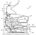
FIG. 1 shows a laser printer to which a paper feed mechanism according to a first embodiment of the present invention is applied. The
また装置本体22には、感光体ドラム26に対向して転写ロール30が配設されており、この転写ロール30は、感光体ドラム26上に形成されたトナー像を搬送される記録紙Pに転写する。この記録紙Pは定着装置31に搬送され、定着装置31は、記録紙P上に形成された未定着トナー像を、例えば加熱圧着等により定着させる機能を有する。また、装置本体22は、図示しない制御部を備えており、この制御部により画像形成時における各種制御の他、後述する記録紙Pの供給、搬送や、オプション装置の制御等を実施している。
In addition, a
また、装置本体22において、符号33はマルチシート材インサータであり、任意のサイズからなる記録紙Pを積載した状態にて装脱着自在に構成されており、シート材搬送方向に対して長いサイズの記録紙Pに対しては、ペーパートレイ34を開いて記録紙Pの搬送を補助するように構成されている。このマルチシート材インサータ33に積載された記録紙Pは、半月形状からなるフィードロール35の回転により感光体ドラム26等からなる作像部へと搬送される。
Further, in the apparatus
更に、装置本体22の下部側には、作像部へ記録紙Pを自動的に供給するためのシート材供給装置として給紙機構36が設けられている。給紙機構36には、装置本体22の一部として構成された本体側給紙部80が設けられると共に、この本体側給紙部80に着脱可能に装着される給紙カセット82が設けられている。給紙カセット82内には、給紙カセット82の両側の側板部にそれぞれ設けられた支軸88を回動中心として揺動可能に支持され、コイルスプリング92により記録紙Pを上昇させるボトムプレート84が設けられている。ボトムプレート84上には、複数枚の記録紙Pが積層された記録紙Pの束(以下、これを「記録紙P」と特に区別する必要がある場合には、「紙束B」という。)が載置されている。
Further, a
図2に示されるように、給紙機構36には、ボトムプレート84の上方にナジャロール94が設けられており、このナジャロール94は、そのロール面95をボトムプレート84上に載置された紙束B上面部の先端側へ圧接させている。給紙機構36は、ナジャロール94を正転方向(矢印F方向)へ回転させることにより、紙束Bの上端側から1枚ないし複数枚の記録紙Pを所定の搬出方向(矢印C方向)へ送り出す。ここで、搬出方向は、ナジャロール94のロール面95の紙束Bとの圧接部における接線方向と略一致し、記録紙Pの後端側から先端側へ向かう方向である。
As shown in FIG. 2, the
給紙機構36には、搬出方向に沿ってナジャロール94の下流側にフィードロール96及びリタードロール98が設けられている。リタードロール98はフィードロール96の下側に配置されており、そのロール面99をフィードロール96のロール面97へ所定の圧接力で圧接させている。また給紙カセット82(図1参照)には、その先端側の側壁部に給紙機構36の一部を構成する搬出ガイド板100が設けられている。搬出ガイド板100は、例えば略へ字状に屈曲された金属プレートからなり、その下端部が給紙カセット82の側壁部に固定され、この側壁部から上方へ延出するように支持されている。
The
図2に示されるように、搬出ガイド板100の上端側には、記録紙Pの搬出方向と略平行に下流側へ延出するガイド部101が屈曲形成されている。このガイド部101には、その先端部から屈曲部側へ向かってコ字状に切り欠かれた切欠部102が形成されている。リタードロール98は、その上端側を切欠部102内を通してガイド部101の上方へ突出させている。紙束Bの上端側からナジャロール94により搬出方向へ送り出された記録紙Pは、その先端側が下方へ撓んだ場合でも、搬出ガイド板100のガイド部101によりリタードロール98の下側へ侵入することが阻止され、フィードロール96とリタードロール98との圧接部であるニップ部Nへ確実に挿入される。
As shown in FIG. 2, a
図3に示されるように、給紙機構36には、ナジャロール94、フィードロール96及びリタードロール98へそれぞれトルクを伝達すると共に、各ロール94,96,98へ伝達されるトルクを制御するためのロール・駆動制御部104が設けられている。ロール・駆動制御部104には、トルクの発生源である駆動モータ106が設けられると共に、この駆動モータ106をナジャロール94、フィードロール96及びリタードロール98へそれぞれトルク伝達可能に連結したギヤ列108が設けられている。ギヤ列108は、駆動ギヤ110及び、この駆動ギヤ110にそれぞれ異なった部位で噛み合ったアイドルギヤ112及び第1従動ギヤ(図示省略)が設けられると共に、アイドルギヤ112に第2従動ギヤ114が設けられている。
As shown in FIG. 3, the
駆動ギヤ110は、駆動モータ106とフィードロール96とを同軸的に連結した駆動軸116の軸方向中間部に配置されている。第2従動ギヤ114は、ナジャロール94に同軸的に固定された第2従動軸118の先端部に配置され、第1従動ギヤは、リタードロール98に同軸的に固定された第1従動軸(図示省略)の先端部に配置されている。またロール・駆動制御部104には、駆動軸116における駆動モータ106と駆動ギヤ110との間に第1ワンウェイクラッチ120が配置されると共に、第2従動軸118におけるナジャロール94と第2従動ギヤ114との間に第2ワンウェイクラッチ122が配置されている。またロール・駆動制御部104には、第1従動軸におけるリタードロール98と第1従動ギヤとの間にトルクリミッタ(図示省略)が配置されている。
The
ここで、第1ワンウェイクラッチ120は、記録紙Pがフィードロール96の線速度より高速で搬出方向へ移動する場合に、この記録紙Pに従動してフィードロール96が回転することが許容されるように、駆動モータ106からフィードロール96へのトルク伝達を制御(遮断)する。第2ワンウェイクラッチ122も、記録紙Pがナジャロール94の線速度より高速で搬出方向へ移動する場合に、この記録紙Pに従動してナジャロール94が回転することが許容されるように、第2従動ギヤ114からナジャロール94へのトルク伝達を制御(遮断)する。
Here, the first one-
またトルクリミッタは、ナジャロール94により紙束Bから送り出された記録紙Pが1枚である場合には、この記録紙Pに従動させてリタードロール98を正転方向へ回転(空転)させ、また紙束Bから送り出された記録紙Pが複数枚である場合には、駆動モータ106からのトルクによりリタードロール98を前記正転方向とは逆の逆転方向へ回転させる。これにより、ナジャロール94により紙束Bから送り出された記録紙Pが1枚である場合には、この1枚の記録紙Pがフィードロール96及びリタードロール98により挟持されて搬送ガイド路124側へ送り出され、またナジャロール94により紙束Bから複数枚の記録紙Pが送り出された場合には、最上部の記録紙Pのみが正転するフィードロール96により搬送ガイド路124側へ送り出され、残りの記録紙Pが逆転するリタードロール98によりナジャロール94側へ送り返される。
Further, when there is one recording paper P sent out from the paper bundle B by the
図2に示されるように、レーザープリンタ21の本体側給紙部80には、フィードロール96及びリタードロール98のニップ部Nの下流側から斜め上方へ傾斜又は湾曲する搬送ガイド路124が設けられており、この搬送ガイド路124は、フィードロール96及びリタードロール98のニップ部Nの下流側から感光体ドラム26及び転写ロール30のニップ部(転写位置)まで延在している。
As shown in FIG. 2, the main body side
搬送ガイド路124は、一定の間隔を空けて互い対向する一対のガイド板128,129等により構成されており、これらのガイド板128,129間に形成されるスリット状の空間内を記録紙Pがガイド板128,129により案内されつつ転写位置まで通過可能とされている。また搬送ガイド路124には、互いに当接する従動ロール131及び駆動ロール132からなる搬送ロール対130が設けられており、この搬送ロール対132は、フィードロール96及びリタードロール98により搬送ガイド路124内へ送り出された1枚の記録紙Pを挟持し、この記録紙Pを搬送ガイド路124に沿って転写位置側へ搬送する。
The
給紙機構36では、ナジャロール94のロール面95における線速度V1(図2参照)がフィードロール96のロール面97における線速度V2よりも所定速度だけ遅くなるように、ギヤ列108における駆動ギヤ110から第2従動ギヤ114までのギヤ比が設定されている。また給紙機構36では、フィードロール96のロール面97における線速度V2が搬送ロール対132における駆動ロール132のロール面における線速度V3よりも所定速度だけ遅くなるように、駆動ロール132の回転速度が設定されている。
In the
図2に示されるように、給紙機構36には、搬出ガイド板100のガイド部101の下側にギャップセンサ134が設けられている。このギャップセンサ134は、ナジャロール94とフィードロール96及びリタードロール98との間の検出位置Dを通過する記録紙Pの下面まで距離を検出し、この距離に対応する検出信号をレーザープリンタ21の制御部(図示省略)に出力する。制御部は、ギャップセンサ134からの検出信号に基づいて記録紙Pの後端が検出位置を通過したことを判断する。
As shown in FIG. 2, the
図1に示されるように、レーザープリンタ21では、オプション装置としてハイキャパシティースタッカ(HCS)71が装置本体22に接続されている。このHCS71は、搬送ロール73を有する搬送路72を形成すると共に、排出ロール74により排出トレイ75に記録紙Pを排出できるように構成されている。この排出ロール74は一定部数毎に左右にずらすことが可能であり、例えばホスト装置からのジョブ情報により記録紙Pを複数部ずらせて排出トレイ75に積載させ、オフセット出力が可能となるように構成されている。また、排出トレイ75は、大量約500枚の記録紙Pを積載できるように設計されている。ここで、装置本体22は、HCS71の搬送路72に記録紙Pを送り込むに際し、制御部による制御信号に基づいてゲート43を切り換えて搬送路72の方向に搬送路を形成すると共に、搬送ロール49を回転させる。画像が形成された記録紙Pは、このゲート43を経由して搬送ロール49によって下流へと搬送され、排出ロール74によりオフセットされた状態で排出トレイ75に積載される。
As shown in FIG. 1, in the
次に、上記のように構成された本実施形態に係る給紙機構36の動作及び作用について説明する。
Next, the operation and action of the
本実施形態に係る給紙機構36が適用されたレーザープリンタ21では、その制御部にサーバ、PC等の情報処理装置からプリント指令及び画像情報が入力すると、制御部が給紙機構36の駆動モータ106及び搬送系の駆動モータ(図示省略)をそれぞれ回転開始させる。これにより、給紙機構36では、駆動モータ106からのトルクがギヤ列108を介してナジャロール94、フィードロール96及びリタードロール98にそれぞれ伝達されると共に、搬送系の駆動モータからの搬送ロール対132の駆動ロール132へ伝達されて搬送ロール対132が線速度V3に対応する回転速度で回転開始し、ナジャロール94は線速度V1に対応する回転速度で回転開始する。またフィードロール96は線速度V2に対応する回転速度で回転開始し、駆動モータ106からのトルクがトルクリミッタを介して伝達されるリタードロール98は、フィードロール96に従動して線速度V2に対応する回転速度で回転する。
In the
給紙機構36では、正転方向へ回転するナジャロール94により給紙カセット82に収容された紙束Bの上端側から1枚ないし複数枚の記録紙Pが搬出方向へ送り出される。先ず、図4を用いて、ナジャロール94により紙束Bの上端側(最上部)から1枚の記録紙P(この記録紙Pは、給紙カセット82に装填された紙束BからN枚目(Nは1以上の自然数、以下同じ)に給紙されるものとする。)が搬出方向へ送り出される場合について説明する。ナジャロール94により搬出方向へ送り出されたN枚目の記録紙Pは、その先端がギャップセンサ134により検出される。このとき、制御部は、ギャップセンサ134からの検出信号の出力タイミング等によりフィードミス発生の有無を判断する。
In the
次いで、N枚目の記録紙Pは、図4(A)に示されるように、先端部がフィードロール96及びリタードロール98のニップ部Nに挿入される。フィードロール96及びリタードロール98は、記録紙Pを挟持しつつナジャロール94の線速度V1よりも高速の線速度V2で記録紙Pを搬出方向へ搬送開始する。このとき、ナジャロール94は、第2ワンウェイクラッチ122によりトルク伝達が遮断されることにより、記録紙Pに従動して線速度V2に対応する回転速度で回転する。また記録紙Pには、ナジャロール94の回転抵抗が作用し、この回転抵抗に対応する張力がニップ部Nとナジャロール94との間に掛け渡された部分に発生する。
Next, as shown in FIG. 4A, the leading end of the Nth recording paper P is inserted into the nip portion N of the
フィードロール96及びリタードロール98により搬出方向へ送り出されたN枚目の記録紙Pは、図4(B)に示されるように、その先端部が搬送ロール対132のニップ部に挿入される。これにより、搬送ロール対132は、記録紙Pを挟持しつつフィードロール96及びリタードロール98の線速度V2よりも高速の線速度V3で記録紙Pを搬送ガイド路124に沿って作像部へ搬送開始する。このとき、フィードロール96は、第1ワンウェイクラッチ120によりトルク伝達が遮断されることにより、記録紙Pに従動して線速度V3に対応する回転速度で回転し、リタードロール98もトルクリミッタによりトルク伝達が遮断されることにより、記録紙Pに従動して線速度V3に対応する回転速度で回転する。
As shown in FIG. 4B, the leading end portion of the Nth recording sheet P fed in the carry-out direction by the
給紙機構36では、搬出方向へ移動するN枚目の記録紙Pの後端部がナジャロール94から離間すると同時に、第2ワンウェイクラッチ122が駆動モータ106からナジャロール94へのトルク伝達を直ちに再開する。これにより、ナジャロール94により紙束Bの上端側から(N+1)枚目の記録紙Pが搬出方向へ送り出される。このとき、図4(C)に示されるように、(N+1)枚目の記録紙Pは、その先端部がN枚目の記録紙Pの後端部の下側に重ねあわされた状態(重送状態)で搬出方向へ送り出される。
In the
ここで、搬出方向へ移動するN枚目の記録紙Pの後端が紙束Bから離間する際には、このN枚目の記録紙Pが、その先端側が搬送ロール対132により挟持されて上方へ湾曲している。これにより、N枚目の記録紙Pは、その後端が紙束Bから離間すると、中立形状(略平面形状)に復元しようとするが、このN枚目の記録紙Pの後端側は、(N+1)枚目の記録紙Pの先端側により下方から支持される。これにより、N枚目の記録紙Pの後端が紙束Bから離間しても、(N+1)枚目の記録紙Pの先端側によりN枚目の記録紙Pの後端側が復元力により瞬間的に中立形状に復元することが確実に防止される。
Here, when the trailing edge of the Nth recording sheet P moving in the unloading direction is separated from the sheet bundle B, the leading end side of the Nth recording sheet P is sandwiched by the
この後、(N+1)枚目の記録紙Pの先端がギャップセンサ134により検出され、ギャップセンサ134は(N+1)枚目の記録紙Pの先端検出信号を制御部へ出力する。制御部は、ギャップセンサ134から(N+1)枚目の記録紙Pの先端検出信号が入力すると、信号入力から所定時間経過後に駆動モータ106の回転を停止させる。具体的には、制御部は、(N+1)枚目の記録紙Pの先端が所定のガイド区間G(図4(D)参照)内に停止するようなタイミングで駆動モータ106の回転を停止させる。
Thereafter, the front end of the (N + 1) th recording paper P is detected by the
ここで、ガイド区間Gは、図4(D)に示されるように、ニップ部Nよりも上流側(ニップ部Nを含まず)であって、かつフィードロール96におけるロール面97の上流側端部及びリタードロール98におけるロール面99の上流側端部にそれぞれ接する接線Tよりも下流側(接線Tを含まず)の区間として設定されている。このように、(N+1)枚目の記録紙Pの先端をガイド区間Gに停止させておくことにより、(N+1)枚目の記録紙Pを作像部へ給紙開始する際に、(N+1)枚目の記録紙Pの先端部が下方又は上方へ撓んでも、(N+1)枚目の記録紙Pをロール面97,99によりニップ部Nへ確実に案内できる。
Here, as shown in FIG. 4D, the guide section G is upstream of the nip portion N (not including the nip portion N) and the upstream end of the
次に、ナジャロール94により紙束Bの上端側(最上部)から複数枚の記録紙Pが搬出方向へ送り出される場合について説明する。給紙機構36では、ナジャロール94により複数枚(N、(N+1)・・・(N+n)枚目の記録紙Pが搬出方向へ送り出された場合には、N、(N+1)・・・(N+n)枚目の記録紙Pの先端がギャップセンサ134により検出され、その先端検出信号が制御部へ出力される。
Next, a case where a plurality of recording sheets P are sent out in the carry-out direction from the upper end side (uppermost part) of the sheet bundle B by the
次いで、N、(N+1)・・・(N+n)枚目の記録紙Pは、それぞれの先端部がフィードロール96及びリタードロール98のニップ部Nに挿入される。このとき、フィードロール96が正転方向へ回転すると共に、リタードロール98が逆転方向へ回転することにより、N枚目の記録紙Pのみがフィードロール96によりニップ部Nから搬出方向へ送り出され、残りの(N+1)・・・(N+n)枚目の記録紙Pは、リタードロール98によりニップ部Nから上流側へ送り返される。
Next, the N, (N + 1)... (N + n) th recording paper P is inserted into the nip portion N of the
一方、制御部は、N枚目の記録紙Pの給紙を開始し、ギャップセンサ134からの先端検出信号が入力した後、この検出信号の入力から所定のしきい時間が経過しても、ギャップセンサ134からの次の先端検出信号が入力しない場合には、記録紙Pの重送発生を判断し、駆動モータ106の回転を停止させる。ここで、重送発生を判断するためのしいき時間は、N枚目の記録紙Pがナジャロール94により搬出開始されてからニップ部Nを抜けるまでの所要時間よりも長い時間に設定されている。これにより、紙束Bから複数枚の記録紙Pが重送された場合にも、N枚目の記録紙Pのみがニップ部Nを抜けて搬送ロール対132により作像部へ搬送され、(N+1)・・・(N+n)枚目の記録紙Pは、リタードロール98によりニップ部Nから上流側へ戻されることにより、その先端がガイド区間Gに位置するように停止する。
On the other hand, the control unit starts feeding the Nth recording sheet P, and after a leading edge detection signal is input from the
以上説明した本実施形態に係る給紙機構36では、紙束BからのN枚目の記録紙Pの搬出時に、ナジャロール94により1枚の記録紙Pが搬出方向へ送り出された場合には、このナジャロール94が紙束Bから搬出方向へ送り出しているN枚目の記録紙Pの後端から離間すると、後続する(N+1)枚目の記録紙Pを先行するN枚目の記録紙Pの下側に重ね合わせた状態で、(N+1)枚目の記録紙Pの先端が紙束Bとフィードロール96及びリタードロール98との中間に設定された所定のガイド区間Gに達するまで搬出方向へ送り出すことにより、搬出方向へ送り出された先行するN枚目の記録紙Pの後端部の下側には(N+1)枚目の記録紙Pの先端部が重なり合う、すなわちN枚目の記録紙Pの後端部に(N+1)枚目の記録紙Pの先端部が下側から接触し、又は十分に近接するような状態(重送状態)で存在するので、湾曲した状態になったN枚目の記録紙P後端が紙束Bから離間する際に、N枚目の記録紙Pの後端側が瞬間的に下方へ向かって中立形状に復元することを(N+1)枚目の記録紙Pの先端部により阻止できる。
In the
また給紙機構36では、ナジャロール94により複数枚の記録紙Pが搬出方向へ送りされた場合にも、(N+1)・・・(N+n)枚目の記録紙Pが、リタードロール98によりニップ部Nから上流側へ戻されることにより、その先端がガイド区間Gに位置するように停止することから、湾曲した状態になったN枚目の記録紙P後端が紙束Bから離間する際に、N枚目の記録紙Pの後端側が瞬間的に下方へ向かって下中立形状に復元することを(N+1)・・・(N+n)枚目の記録紙Pの先端部により阻止できる。
In the
この結果、本実施形態に係る給紙機構36によれば、湾曲状態となったN枚目の記録紙Pの後端側が中立形状に復元する際に生じるしなり音や、中立形状に復元する記録紙Pの後端が搬出ガイド板100へ当たる際の打音の発生を防止でき、また、このような記録紙Pのしなり音や打音を防止するためだけに専用の部品を追加する必要がないので、装置の部品点数が増加して装置(給紙機構)の構造が複雑化することも防止できる。
As a result, according to the
(第2の実施形態)
図5には、本発明の第2の実施形態に係る給紙機構が示されている。この給紙機構140は、第1の実施形態に係る給紙機構36に代えて、レーザープリンタ21に適用可能なものであり、第1の実施形態に係る給紙機構36と同一の部分には同一符号を付して説明を省略する。
(Second Embodiment)
FIG. 5 shows a paper feed mechanism according to the second embodiment of the present invention. This
本実施形態に係る給紙機構140が第1の実施形態に係る給紙機構36と異なる点は、給紙機構36では搬出ガイド板100の下方にギャップセンサ134が設けられていたのに対し、このようなギャップセンサが給紙機構140では省略されている点である。給紙機構140では、制御部が紙束Bからの記録紙Pのフィードミス発生の有無をフィードロール96及びリタードロール98と搬送ロール対132との間に配置されて記録紙Pの先端及び後端を検出するエッジセンサ142からの検出信号に基づいて判断する。
The difference between the
図5(B)に示されるように、給紙機構140は、第1の実施形態に係る給紙機構36と同様に、ギヤ列144を介してナジャロール94、フィードロール96及びリタードロール98へそれぞれ駆動モータ106からのトルクを伝達すると共に、各ロール94,96,98へ伝達されるトルクを制御するためのロール・駆動制御部146が設けられている。
As shown in FIG. 5B, the
ここで、給紙カセット82に収容された紙束Bの先端からガイド区間Gの終端までの距離をL2、ナジャロール94のロール面95の紙束Bへの圧接点PPからフィードロール96及びリタードロール98のニップ部Nまでの距離をL1、給紙カセット82に収容された紙束Bの先端からガイド区間Gの始端までの距離をL3、ナジャロール94のロール面95における線速度をV1、フィードロール96のロール面97における線速度をV2とした場合、ギヤ列144は、ナジャロール94の線速度V1が下記(1)式を充足させるように、ナジャロール94の回転速度及びフィードロール96の回転速度を設定する。
V2×(L3/L1)<V1<V2×(L2/L1)・・・(1)
Here, the distance from the front end of the paper bundle B accommodated in the
V2 × (L3 / L 1 ) <V1 <V2 × (L 2 / L 1 ) (1)
すなわち、フィードロール96は駆動軸116を介して駆動モータ106に連結され、駆動モータ106とフィードロール96の減速比が1であることから、ナジャロール94の回転速度とフィードロール96の回転速度との比は、ギヤ列144における駆動ギヤ110から第2従動ギヤ114までの減速比Rによって決まり、ナジャロール94の線速度及びフィードロール96の線速度は、それぞれのロール径及び回転速度によって決まるので、ギヤ列144では、減速比Rが上記(1)式及びナジャロール94及びフィードロール96のロール径にそれぞれ対応するように設定される。
Ie, the
次に、上記のように構成された本実施形態に係る給紙機構140の動作及び作用について説明する。
Next, the operation and action of the
本実施形態に係る給紙機構140が適用されたレーザープリンタ21では、その制御部にサーバ、PC等の情報処理装置からプリント指令及び画像情報が入力すると、制御部が給紙機構140の駆動モータ106及び搬送系の駆動モータ(図示省略)をそれぞれ回転開始させる。これにより、給紙機構140では、駆動モータ106からのトルクがギヤ列144を介してナジャロール94、フィードロール96及びリタードロール98にそれぞれ伝達されると共に、搬送系の駆動モータからの搬送ロール対132の駆動ロール132へ伝達されて搬送ロール対132が線速度V3に対応する回転速度で回転開始し、ナジャロール94は線速度V1に対応する回転速度で回転開始する。またフィードロール96は線速度V2に対応する回転速度で回転開始し、駆動モータ106からのトルクがトルクリミッタを介して伝達されるリタードロール98は、フィードロール96に従動して線速度V2に対応する回転速度で回転する。
In the
給紙機構140では、正転方向へ回転するナジャロール94により給紙カセット82に収容された紙束Bの上端側から1枚ないし複数枚の記録紙Pが搬出方向へ送り出される。先ず、ナジャロール94により紙束Bの上端側(最上部)から1枚の記録紙P(この記録紙Pは、給紙カセット82に装填された紙束BからN枚目(Nは2以上の自然数)に給紙されるものとする。)が搬出方向へ送り出される場合について説明する。ナジャロール94により搬出方向へ送り出されたN枚目の記録紙Pは、先端部がフィードロール96及びリタードロール98のニップ部Nに挿入される(図4(A)参照)。フィードロール96及びリタードロール98は、記録紙Pを挟持しつつナジャロール94の線速度V1よりも高速の線速度V2で記録紙Pを搬出方向へ搬送開始する(図4(B)参照)。このとき、ナジャロール94は、第2ワンウェイクラッチ122によりトルク伝達が遮断されることにより、記録紙Pに従動して線速度V2に対応する回転速度で回転する。また記録紙Pには、ナジャロール94の回転抵抗が作用し、この回転抵抗に対応する張力がニップ部Nとナジャロール94との間に掛け渡された部分に発生する。
In the
フィードロール96及びリタードロール98により搬出方向へ送り出されたN枚目の記録紙Pは、その先端部が搬送ロール対132のニップ部に挿入される。これにより、搬送ロール対132は、記録紙Pを挟持しつつフィードロール96及びリタードロール98の線速度V2よりも高速の線速度V3で記録紙Pを搬送ガイド路124に沿って作像部へ搬送開始する。このとき、フィードロール96は、第1ワンウェイクラッチ120によりトルク伝達が遮断されることにより、記録紙Pに従動して線速度V3に対応する回転速度で回転し、リタードロール98もトルクリミッタによりトルク伝達が遮断されることにより、記録紙Pに従動して線速度V3に対応する回転速度で回転する。
The leading end portion of the Nth recording sheet P fed in the unloading direction by the
給紙機構140では、搬出方向へ移動するN枚目の記録紙Pの後端部がナジャロール94から離間すると同時に、第2ワンウェイクラッチ122が駆動モータ106からナジャロール94へのトルク伝達を直ちに再開する。これにより、ナジャロール94により紙束Bの上端側から(N+1)枚目の記録紙Pが搬出方向へ送り出される。このとき、第1の実施形態に係る給紙機構36の場合と同様に、(N+1)枚目の記録紙Pは、その先端部がN枚目の記録紙Pの後端部の下側に重ねあわされた状態(重送状態)で搬出方向へ送り出される(図4(C)参照)。このとき、N枚目の記録紙Pの後端が紙束Bから離間しても、(N+1)枚目の記録紙Pの先端側によりN枚目の記録紙Pの後端側が復元力により瞬間的に中立形状に復元することが確実に防止される。
In the
この後、制御部は、エッジセンサ142からのN枚目の記録紙Pの先端検出信号に基づいてN枚目の記録紙Pがニップ部Nを抜けたタイミングに同期し、駆動モータ106の回転を停止させる。これにより、ナジャロール94が回転停止し、(N+1)枚目の記録紙Pの搬出方向への移動が停止する。このとき、(N+1)枚目の記録紙Pの先端が所定のガイド区間G内に達している。
Thereafter, the control unit synchronizes with the timing when the Nth recording sheet P passes through the nip N based on the leading edge detection signal of the Nth recording sheet P from the edge sensor 142, and rotates the
次に、ナジャロール94により紙束Bの上端側(最上部)から複数枚の記録紙Pが搬出方向へ送り出される場合について説明する。給紙機構140では、ナジャロール94により複数枚(N、(N+1)・・・(N+n)枚目の記録紙Pが搬出方向へ送り出された場合には、N、(N+1)・・・(N+n)枚目の記録紙Pの先端部がそれぞれフィードロール96及びリタードロール98のニップ部Nに挿入される。このとき、フィードロール96が正転方向へ回転すると共に、リタードロール98が逆転方向へ回転することにより、N枚目の記録紙Pのみがフィードロール96によりニップ部Nから搬出方向へ送り出され、残りの(N+1)・・・(N+n)枚目の記録紙Pは、リタードロール98によりニップ部Nから上流側(ガイド区間G)へ送り返される。
Next, a case where a plurality of recording sheets P are sent out in the carry-out direction from the upper end side (uppermost part) of the sheet bundle B by the
一方、制御部は、エッジセンサ142からのN枚目の記録紙Pの先端検出信号に基づいてN枚目の記録紙Pがニップ部Nを抜けたタイミングに同期し、駆動モータ106の回転を停止させる。これにより、ナジャロール94が回転停止し、(N+1)枚目の記録紙Pの搬出方向への移動が停止する。このとき、(N+1)枚目の記録紙Pの先端が所定のガイド区間G内に達している。
On the other hand, the control unit synchronizes with the timing when the Nth recording sheet P passes through the nip N based on the leading edge detection signal of the Nth recording sheet P from the edge sensor 142, and rotates the
以上説明した本実施形態に係る給紙機構140でも、第1の実施形態に係る給紙機構36と基本的に同一の作用及び効果が得られることに加え、ナジャロール94とフィードロール96及びリタードロール98との間に記録紙Pの重送を検出するためのギャップセンサが存在しない場合でも、(N+1)枚目の記録紙P又は(N+1)・・・(N+n)枚目の記録紙Pの先端がガイド区間Gに達したタイミングで駆動モータ106の回転を停止できる。
The
なお、本実施形態に係る給紙機構140では、制御部がN枚目の記録紙Pがニップ部Nを抜けたタイミングをギャップセンサ134からの検出信号に基づいて判断しているが、ナジャロール94(駆動モータ106)の回転開始からの時間をタイマにより計時することにより、N枚目の記録紙Pがニップ部Nを抜けたタイミングを判断するようにしても良い。
In the
また第1及び第2の実施形態に係る給紙機構36,140では、(N+1)枚目の記録紙P又は(N+1)・・・(N+n)枚目の記録紙Pの先端を所定のガイド区間Gに停止させ、この記録紙Pをロール面97,99によりニップ部Nへガイドしていたが、(N+1)枚目の記録紙P又は(N+1)・・・(N+n)枚目の記録紙Pの先端を紙束Bの先端から僅かでも延出させておくだけでも、N枚目の記録紙Pが紙束Bから離間する際のしなり音及び打音を低減できる。このことから、しなり音及び打音の低減のみを考慮する場合には、第1の実施形態に係る給紙機構36では、(N+1)枚目の記録紙P又は(N+1)・・・(N+n)枚目の記録紙Pの先端がガイド区間Gに達する前に、駆動モータ106の回転を停止させても良い。また第2の実施形態に係る給紙機構36では、ギヤ列144は、ナジャロール94の線速度V1が下記(2)式を充足させるように、ナジャロール94の回転速度を設定しても良い。
In the
0<V1<V2×(L2/L1)・・・(2) 0 <V1 <V2 × (L 2 / L 1 ) (2)
36 給紙機構(シート材供給装置)
80 本体側給紙部
82 給紙カセット(シート材収容部)
94 ナジャロール(搬出手段)
96 フィードロール(給送手段)
98 リタードロール(給送手段)
104 ロール・駆動制御部
106 駆動モータ
108 ギヤ列
122 第2ワンウェイクラッチ
124 搬送ガイド路
130 搬送ロール対
134 ギャップセンサ(先端センサ)
140 給紙機構(シート材供給装置)
142 エッジセンサ
144 ギヤ列
146 ロール・駆動制御部
B 紙束
P 記録紙
36 Paper feed mechanism (sheet material supply device)
80 Main body side
94 Najaroll (unloading means)
96 Feed roll (feeding means)
98 retard roll (feeding means)
104 Roll /
140 Paper feed mechanism (sheet material supply device)
142
Claims (6)
前記シート材収容部に収容されたシート束の上面先端側にロール面を圧接させ、所定の搬出方向に対応する正転方向へ回転して押出力を作用させ、該押出力によりシート束の上端側に積層されたシート材を前記搬出方向へ送り出し、該シート材をシート束から分離するナジャロールと、
前記ナジャロールの回転及び回転停止を制御するロール駆動・制御部と、
前記搬出方向に沿って前記シート材収容部の下流側に配置され、前記ナジャロールによりシート束から送り出されたシート材を、継続して前記搬出方向へ送り出す給送手段と、
を備え、
前記ナジャロールは、
前記シート束からのシート材の搬出時に、前記正転方向へ回転し、前記シート束から前記搬出方向へ送り出している先行するシート材の後端から離間すると、後続するシート材を、先行するシート材の下側に重ね合わせた状態で、該後続するシート材の先端が前記シート束と前記給送手段との中間に設定された所定のガイド位置に達するまで前記搬出方向へ送り出すとともに、前記後続するシート材の先端が前記ガイド位置に達すると、前記回転が停止するように、前記ロール駆動・制御部によって制御されていることを特徴とするシート材供給装置。 A sheet material accommodating portion that accommodates a sheet bundle in which a plurality of sheet materials are laminated;
A roll surface is pressed against the top end side of the upper surface of the sheet bundle accommodated in the sheet material accommodating portion, and is rotated in a normal rotation direction corresponding to a predetermined carry-out direction to exert a pushing force. feeding the sheet material stacked on a side to the carry-out direction, the nudger roll to separate the sheet from the sheet stack,
A roll drive / control unit for controlling rotation and rotation stoppage of the nudger roll;
A feeding means that is arranged on the downstream side of the sheet material accommodating portion along the unloading direction and continuously feeds the sheet material fed from the sheet bundle by the nudger roll in the unloading direction;
With
The najalol is
During unloading of the sheet material from the sheet bundle, the sheet is rotated to the forward direction and away from the rear end of the sheet the preceding has turned out to the carrying-out direction from said sheet bundle, the successive sheet material, prior In the state of being superimposed on the lower side of the material, the subsequent sheet material is fed in the carry-out direction until reaching the predetermined guide position set in the middle between the sheet bundle and the feeding means, and the subsequent The sheet material supply device is controlled by the roll driving / controlling unit so that the rotation is stopped when the leading edge of the sheet material to be reached reaches the guide position .
前記ロール駆動・制御部は、前記ナジャロールのロール面における線速度V1が下記(1)式を充足させる速度となるように、ナジャロールの回転速度及び前記フィードロールの回転速度を設定することを特徴とする請求項4又は請求項5に記載のシート材供給装置。
0<V1<V2×(L2/L1)・・・(1) The distance from the leading end of the sheet bundle accommodated in the sheet material accommodating portion to the guide position is L2, from the pressure contact to the sheet bundle on the roll surface of the nudger roll, to the nip point of the feed roll and the retard roll When the distance is L1, the linear velocity on the roll surface of the naja roll is V1, and the linear velocity on the roll surface of the feed roll is V2,
The roll drive / control unit sets the rotation speed of the nudger roll and the rotation speed of the feed roll so that the linear velocity V1 on the roll surface of the nudger roll is a speed that satisfies the following expression (1). The sheet material supply device according to claim 4 or 5, characterized in that
0 <V1 <V2 × (L2 / L1) (1)
Priority Applications (3)
| Application Number | Priority Date | Filing Date | Title |
|---|---|---|---|
| JP2005187182A JP4428302B2 (en) | 2005-06-27 | 2005-06-27 | Sheet material supply device |
| US11/389,016 US7770881B2 (en) | 2005-06-27 | 2006-03-27 | Sheet material feeding device having a sheet guide part |
| CNB2006100721867A CN100547493C (en) | 2005-06-27 | 2006-04-18 | Sheet feeding device |
Applications Claiming Priority (1)
| Application Number | Priority Date | Filing Date | Title |
|---|---|---|---|
| JP2005187182A JP4428302B2 (en) | 2005-06-27 | 2005-06-27 | Sheet material supply device |
Publications (2)
| Publication Number | Publication Date |
|---|---|
| JP2007001759A JP2007001759A (en) | 2007-01-11 |
| JP4428302B2 true JP4428302B2 (en) | 2010-03-10 |
Family
ID=37597425
Family Applications (1)
| Application Number | Title | Priority Date | Filing Date |
|---|---|---|---|
| JP2005187182A Expired - Fee Related JP4428302B2 (en) | 2005-06-27 | 2005-06-27 | Sheet material supply device |
Country Status (3)
| Country | Link |
|---|---|
| US (1) | US7770881B2 (en) |
| JP (1) | JP4428302B2 (en) |
| CN (1) | CN100547493C (en) |
Families Citing this family (10)
| Publication number | Priority date | Publication date | Assignee | Title |
|---|---|---|---|---|
| EP2455313B1 (en) * | 2009-07-13 | 2015-09-09 | Canon Kabushiki Kaisha | Sheet feed device and image forming device |
| TW201318877A (en) * | 2011-11-11 | 2013-05-16 | Primax Electronics Ltd | Automatic document feeder |
| JP5825999B2 (en) * | 2011-11-30 | 2015-12-02 | キヤノン株式会社 | Sheet feeding device |
| JP6000572B2 (en) * | 2012-02-29 | 2016-09-28 | キヤノン株式会社 | Sheet feeding apparatus and image forming apparatus |
| JP6421539B2 (en) * | 2014-10-16 | 2018-11-14 | 株式会社リコー | RECORDING MEDIUM CONVEYING DEVICE, IMAGE FORMING DEVICE, AND CONTROL PROGRAM |
| JP6506016B2 (en) * | 2014-11-28 | 2019-04-24 | 理想科学工業株式会社 | Paper feeder |
| JP6575749B2 (en) * | 2015-06-26 | 2019-09-18 | 株式会社リコー | Sheet feeding apparatus and image forming apparatus |
| US10294053B2 (en) | 2016-04-28 | 2019-05-21 | Canon Kabushiki Kaisha | Image forming apparatus and feeding apparatus |
| CN111453477B (en) * | 2019-01-21 | 2022-03-11 | 柯尼卡美能达办公系统研发(无锡)有限公司 | Sheet conveying mechanism and image forming apparatus |
| JP2022102562A (en) * | 2020-12-25 | 2022-07-07 | キヤノン株式会社 | Recording device, recording method, storage medium, and program |
Family Cites Families (9)
| Publication number | Priority date | Publication date | Assignee | Title |
|---|---|---|---|---|
| JPH0781792A (en) | 1993-09-17 | 1995-03-28 | Sharp Corp | Paper feeding device |
| JP2659344B2 (en) * | 1995-02-10 | 1997-09-30 | 日本電気ロボットエンジニアリング株式会社 | Friction feeding mechanism for paper sheets |
| US6332608B1 (en) * | 1999-01-06 | 2001-12-25 | Canon Kabushiki Kaisha | Sheet feeding apparatus |
| JP3595762B2 (en) | 2000-08-24 | 2004-12-02 | キヤノン株式会社 | Sheet feeding apparatus and image forming apparatus having the same |
| KR100385052B1 (en) * | 2001-01-29 | 2003-05-23 | 삼성전자주식회사 | Sheet conveying appratus for a image information processor |
| JP2004331357A (en) * | 2003-05-09 | 2004-11-25 | Ricoh Co Ltd | Sheet transporting device and image forming apparatus equipped with it |
| JP2005200133A (en) * | 2004-01-14 | 2005-07-28 | Oki Data Corp | Image forming device |
| JP2006256739A (en) * | 2005-03-16 | 2006-09-28 | Ricoh Co Ltd | Paper feeding device and image forming device |
| JP2006327700A (en) | 2005-05-23 | 2006-12-07 | Canon Inc | Sheet feeding device and image forming device |
-
2005
- 2005-06-27 JP JP2005187182A patent/JP4428302B2/en not_active Expired - Fee Related
-
2006
- 2006-03-27 US US11/389,016 patent/US7770881B2/en not_active Expired - Fee Related
- 2006-04-18 CN CNB2006100721867A patent/CN100547493C/en not_active Expired - Fee Related
Also Published As
| Publication number | Publication date |
|---|---|
| CN100547493C (en) | 2009-10-07 |
| US20070008588A1 (en) | 2007-01-11 |
| JP2007001759A (en) | 2007-01-11 |
| CN1892454A (en) | 2007-01-10 |
| US7770881B2 (en) | 2010-08-10 |
Similar Documents
| Publication | Publication Date | Title |
|---|---|---|
| JP4428302B2 (en) | Sheet material supply device | |
| JP5258598B2 (en) | Image forming apparatus | |
| JP2007168955A (en) | Image forming device and carrying device | |
| JP2008280121A (en) | Sheet feeder, image reading device, and image forming device | |
| JP4814066B2 (en) | Sheet-like medium conveying apparatus, image forming apparatus, and sheet-like medium conveying method | |
| JP2009083988A (en) | Sheet feeding device, image forming device, control method for image forming device, program, and recording medium | |
| JP2003155130A (en) | Image forming device | |
| JP2008019069A (en) | Paper feeding mechanism and image forming device having it | |
| JP2000044085A (en) | Image forming device and jam releasing mechanism | |
| JP2924203B2 (en) | Sheet material transport device | |
| JP6669989B2 (en) | Paper feeder and image forming apparatus | |
| JP2007062879A (en) | Sheet transport device, sheet processing device, and image forming device | |
| JP4713418B2 (en) | Sheet conveying apparatus and image forming apparatus | |
| JP4249050B2 (en) | Paper feeding device and image forming apparatus | |
| JP6684464B2 (en) | Switchback transport device and image forming apparatus | |
| JP4415917B2 (en) | Recording sheet conveying mechanism and image forming apparatus | |
| JP3548316B2 (en) | Paper supply device and image forming device | |
| JP2006298515A (en) | Paper feeding device and image forming device using the same | |
| JP2714521B2 (en) | Paper transport device | |
| JP5940995B2 (en) | Paper feeding device and image forming apparatus | |
| JP2004059276A (en) | Sheet feeding device and image forming device equipped with the same | |
| JP2005298117A (en) | Sheet feeder and image forming device using it | |
| JPH05147831A (en) | Paper feeding device | |
| JP5773589B2 (en) | Sheet conveying apparatus and image forming apparatus | |
| JP2001148760A (en) | Sheet transfer device |
Legal Events
| Date | Code | Title | Description |
|---|---|---|---|
| A621 | Written request for application examination |
Free format text: JAPANESE INTERMEDIATE CODE: A621 Effective date: 20080317 |
|
| A977 | Report on retrieval |
Free format text: JAPANESE INTERMEDIATE CODE: A971007 Effective date: 20090716 |
|
| A131 | Notification of reasons for refusal |
Free format text: JAPANESE INTERMEDIATE CODE: A131 Effective date: 20090811 |
|
| A521 | Request for written amendment filed |
Free format text: JAPANESE INTERMEDIATE CODE: A523 Effective date: 20091013 |
|
| TRDD | Decision of grant or rejection written | ||
| A01 | Written decision to grant a patent or to grant a registration (utility model) |
Free format text: JAPANESE INTERMEDIATE CODE: A01 Effective date: 20091124 |
|
| A01 | Written decision to grant a patent or to grant a registration (utility model) |
Free format text: JAPANESE INTERMEDIATE CODE: A01 |
|
| FPAY | Renewal fee payment (event date is renewal date of database) |
Free format text: PAYMENT UNTIL: 20121225 Year of fee payment: 3 |
|
| R150 | Certificate of patent or registration of utility model |
Ref document number: 4428302 Country of ref document: JP Free format text: JAPANESE INTERMEDIATE CODE: R150 Free format text: JAPANESE INTERMEDIATE CODE: R150 |
|
| A61 | First payment of annual fees (during grant procedure) |
Free format text: JAPANESE INTERMEDIATE CODE: A61 Effective date: 20091207 |
|
| FPAY | Renewal fee payment (event date is renewal date of database) |
Free format text: PAYMENT UNTIL: 20121225 Year of fee payment: 3 |
|
| FPAY | Renewal fee payment (event date is renewal date of database) |
Free format text: PAYMENT UNTIL: 20131225 Year of fee payment: 4 |
|
| LAPS | Cancellation because of no payment of annual fees |