EP3023370A1 - Denester with adjustable inclined cartridge - Google Patents
Denester with adjustable inclined cartridge Download PDFInfo
- Publication number
- EP3023370A1 EP3023370A1 EP14193681.5A EP14193681A EP3023370A1 EP 3023370 A1 EP3023370 A1 EP 3023370A1 EP 14193681 A EP14193681 A EP 14193681A EP 3023370 A1 EP3023370 A1 EP 3023370A1
- Authority
- EP
- European Patent Office
- Prior art keywords
- guide
- denester
- inclination
- stack
- adjustable
- Prior art date
- Legal status (The legal status is an assumption and is not a legal conclusion. Google has not performed a legal analysis and makes no representation as to the accuracy of the status listed.)
- Granted
Links
- 238000007789 sealing Methods 0.000 abstract description 2
- 238000000034 method Methods 0.000 description 3
- 230000007704 transition Effects 0.000 description 2
- 238000000418 atomic force spectrum Methods 0.000 description 1
- 230000003247 decreasing effect Effects 0.000 description 1
- 238000011161 development Methods 0.000 description 1
- 230000018109 developmental process Effects 0.000 description 1
- 238000009434 installation Methods 0.000 description 1
- 238000004806 packaging method and process Methods 0.000 description 1
Images


Classifications
-
- B—PERFORMING OPERATIONS; TRANSPORTING
- B65—CONVEYING; PACKING; STORING; HANDLING THIN OR FILAMENTARY MATERIAL
- B65G—TRANSPORT OR STORAGE DEVICES, e.g. CONVEYORS FOR LOADING OR TIPPING, SHOP CONVEYOR SYSTEMS OR PNEUMATIC TUBE CONVEYORS
- B65G59/00—De-stacking of articles
- B65G59/10—De-stacking nested articles
- B65G59/107—De-stacking nested articles by means of rotary devices or endless elements
- B65G59/108—De-stacking nested articles by means of rotary devices or endless elements the axis of rotation being substantially parallel to the axis of the stack
-
- B—PERFORMING OPERATIONS; TRANSPORTING
- B65—CONVEYING; PACKING; STORING; HANDLING THIN OR FILAMENTARY MATERIAL
- B65G—TRANSPORT OR STORAGE DEVICES, e.g. CONVEYORS FOR LOADING OR TIPPING, SHOP CONVEYOR SYSTEMS OR PNEUMATIC TUBE CONVEYORS
- B65G59/00—De-stacking of articles
- B65G59/06—De-stacking from the bottom of the stack
- B65G59/061—De-stacking from the bottom of the stack articles being separated substantially along the axis of the stack
- B65G59/062—De-stacking from the bottom of the stack articles being separated substantially along the axis of the stack by means of reciprocating or oscillating escapement-like mechanisms
- B65G59/065—De-stacking from the bottom of the stack articles being separated substantially along the axis of the stack by means of reciprocating or oscillating escapement-like mechanisms by angularly displacing the stack relatively to the lower most article or vice versa
-
- B—PERFORMING OPERATIONS; TRANSPORTING
- B65—CONVEYING; PACKING; STORING; HANDLING THIN OR FILAMENTARY MATERIAL
- B65G—TRANSPORT OR STORAGE DEVICES, e.g. CONVEYORS FOR LOADING OR TIPPING, SHOP CONVEYOR SYSTEMS OR PNEUMATIC TUBE CONVEYORS
- B65G59/00—De-stacking of articles
- B65G59/10—De-stacking nested articles
-
- B—PERFORMING OPERATIONS; TRANSPORTING
- B65—CONVEYING; PACKING; STORING; HANDLING THIN OR FILAMENTARY MATERIAL
- B65G—TRANSPORT OR STORAGE DEVICES, e.g. CONVEYORS FOR LOADING OR TIPPING, SHOP CONVEYOR SYSTEMS OR PNEUMATIC TUBE CONVEYORS
- B65G57/00—Stacking of articles
-
- B—PERFORMING OPERATIONS; TRANSPORTING
- B65—CONVEYING; PACKING; STORING; HANDLING THIN OR FILAMENTARY MATERIAL
- B65G—TRANSPORT OR STORAGE DEVICES, e.g. CONVEYORS FOR LOADING OR TIPPING, SHOP CONVEYOR SYSTEMS OR PNEUMATIC TUBE CONVEYORS
- B65G57/00—Stacking of articles
- B65G57/02—Stacking of articles by adding to the top of the stack
- B65G57/03—Stacking of articles by adding to the top of the stack from above
- B65G57/06—Gates for releasing articles
-
- B—PERFORMING OPERATIONS; TRANSPORTING
- B65—CONVEYING; PACKING; STORING; HANDLING THIN OR FILAMENTARY MATERIAL
- B65G—TRANSPORT OR STORAGE DEVICES, e.g. CONVEYORS FOR LOADING OR TIPPING, SHOP CONVEYOR SYSTEMS OR PNEUMATIC TUBE CONVEYORS
- B65G57/00—Stacking of articles
- B65G57/02—Stacking of articles by adding to the top of the stack
- B65G57/08—Stacking of articles by adding to the top of the stack articles being tilted or inverted prior to depositing
-
- B—PERFORMING OPERATIONS; TRANSPORTING
- B65—CONVEYING; PACKING; STORING; HANDLING THIN OR FILAMENTARY MATERIAL
- B65G—TRANSPORT OR STORAGE DEVICES, e.g. CONVEYORS FOR LOADING OR TIPPING, SHOP CONVEYOR SYSTEMS OR PNEUMATIC TUBE CONVEYORS
- B65G57/00—Stacking of articles
- B65G57/02—Stacking of articles by adding to the top of the stack
- B65G57/16—Stacking of articles of particular shape
- B65G57/165—Stacking of articles of particular shape nested
-
- B—PERFORMING OPERATIONS; TRANSPORTING
- B65—CONVEYING; PACKING; STORING; HANDLING THIN OR FILAMENTARY MATERIAL
- B65G—TRANSPORT OR STORAGE DEVICES, e.g. CONVEYORS FOR LOADING OR TIPPING, SHOP CONVEYOR SYSTEMS OR PNEUMATIC TUBE CONVEYORS
- B65G59/00—De-stacking of articles
- B65G59/08—De-stacking after preliminary tilting of the stack
-
- B—PERFORMING OPERATIONS; TRANSPORTING
- B65—CONVEYING; PACKING; STORING; HANDLING THIN OR FILAMENTARY MATERIAL
- B65G—TRANSPORT OR STORAGE DEVICES, e.g. CONVEYORS FOR LOADING OR TIPPING, SHOP CONVEYOR SYSTEMS OR PNEUMATIC TUBE CONVEYORS
- B65G60/00—Simultaneously or alternatively stacking and de-stacking of articles
Definitions
- a denester according to the invention is a stacking device for trays for use on a packaging machine in the form of a traysealer.
- Object of the present invention is to provide a denester, which can accommodate a higher number of shells to less frequently refill the magazine, the bearing force should remain largely constant during Entstapelvorgangs.
- the denester according to the invention comprises a magazine for accommodating at least one stack of trays, the magazine comprising a first vertical guide and a second guide, the second guide having a tilt relative to the first guide.
- the Denester is characterized by the fact that the inclination is adjustable.
- the advantage over a rigid system is that the stack can be significantly increased with the shells and thus the capacity is increased. At the same time, the reliability of the stacking process is improved by a more constant contact force.
- the inclination is preferably automatically adjustable in order to automatically obtain a slope corresponding to the stack, which ensures an optimized Abstapellui.
- the inclination at an angle of 30 ° to 70 °, preferably from 50 ° to 70 °, adjustable in order to obtain a largely constant and adapted to the properties of the shells or the stack of trays supporting force of the shell flange, for example, to the Abstapelschrauben ,
- the shell flange is the laterally outwardly projecting edge surface which is detected by the destacker screws to separate individual trays from the stack and drop onto a transport unit.
- a third arcuate guide is provided between the first and second guides to provide a transition between the second guide receiving the stack of trays and the vertical guide feeding the trays to the stacking screws
- the third guide has an outer guide with an outer radius, wherein the outer radius is variable in order to optimize the movement of the shells or the stack of shells along the transition, for example with respect to the friction of the shell flanges on the guide inner sides and thus increase the process reliability of the denester.
- the first, second and third guide are adjustable with respect to their inner dimensions in order to be adaptable to different outer dimensions of a shell flange, namely length and width.
- the second guide has a length of at least 600 mm.
- the second guide is rotatably mounted on a frame of the denester to allow tilt adjustment in a structurally simple manner.
- At least one spring element is provided as a connection between the second guide and a frame of the denester to automatically adjust the inclination depending on the weight of the stack.
- the spring element is a gas spring, which has an approximately constant pressure force over the adjustment path.
- a spring force of the spring element is preferably adjustable in order to adapt the automatic tilt adjustment to different weights with different shapes, sizes and / or weights of shells.
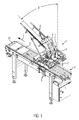
- Fig. 1 shows a denester 1 according to the invention, which is arranged on a transport unit 2 for trays 3.
- the denester 1 comprises a magazine 4 for receiving a stack 5 of trays 3, as shown in FIG Fig. 2 shown.
- the magazine 5 has a first vertical guide 6 in the area of several stacking screws 7 and a second guide 8 in the upper area of the magazine 4.
- the second guide 8 for the stack 5 has a slope ⁇ relative to the first guide 6 or to a vertical .
- a third curved guide 9 is attached. New trays 3 are placed on the second guide 8 and slip gravitationally automatically towards the first guide 6.
- Individual trays 3 stacked on the transport unit 2 are fed by means of driven conveyor belts 20 in a transport direction T to a next station, for example a filling station of a tray sealing machine.
- Fig. 2 shows in a side view the denester 1 with a filled magazine 4 in a first position.
- the second guide 8 with respect to the first vertical guide 6 has an inclination ⁇ of, for example, 70 °.
- the second guide 8 comprises a lower support 10 and two laterally arranged equipment 11.
- the lower support 10 and the two systems 11 are rigidly connected.
- the second guide 8 is rotatably arranged by means of the two systems 11 on a frame 12 of the denester 1 by one end 13 of the systems 11 is mounted for example by means of a screw or bolt 21 on the frame 12.
- Two gas pressure springs 14 are connected to the second guide 8 at one of their ends and to a frame 15 of the denester 1 at the other end and thus support the stack 5 or the second guide 8 against the frame 15 from.
- the second guide 8 has, for example, a length L of 600 mm.
- the operation of the tilt adjustment of the second guide 8 will be explained in more detail below.
- the Denester 1 stacks 7 individual trays with the destacker screws. Further shells 3 of the stack 5 slip automatically. This results in a reduction in the height of the stack 5 during operation and in a reduction of the weight by the shells 3 on the second guide 8. With denesters 1 with a high stacking performance, the stack 5 can be used up within a few minutes. So a constant refilling is required.
- Fig. 3 shows in a side view the denester 1 with a partially emptied magazine 4 in a second position.
- the decreasing weight by the reduced number of shells 3 in the stack 5 causes the gas springs 14, the second guide 8 continue to push up in the direction of arrow or increase the inclination, ie reduce the angle ß, the fewer shells 3 on the second guide 8 are located.
- the inclination ß in FIG. 3 has an angle of 55 °.
- the pressure of the stack 5 can be kept approximately constant on the bottom to be stacked shell 3.
- gas spring 14 is replaced by a pneumatic cylinder and by means of a pressure regulator, which is controllable in dependence on the pressure of the stack 5 on the lowest stacked shell 3, has a force curve to the inclination ß corresponding to the stack. 5 to stop automatically.
- a linear motor drive instead of the gas spring 14 may be provided.
- the third guide 9 includes an inner guide 16 having an inner radius Ri and an outer guide 17 having an outer radius Ra.
- the outer guide 17 is connected to the frame 12 at a plurality of fastening points 18, and each of these fastening points 18 is changeable in its position relative to the outer guide 17 and / or to the frame 12. This causes curvature of the outer guide 17 relative to the shells 3 is adaptable to prevent jamming or excessive friction of the shells 3 in the magazine 4 in the third guide 9.
Abstract
Die Erfindung betrifft einen Denester (1) zum Einsatz an einer Schalenverschließmaschine, mit einem Magazin (4) zur Aufnahme wenigstens eines Stapels (5) von Schalen (3), wobei das Magazin (4) eine erste vertikale Führung (6) und eine zweite Führung (8) umfasst, wobei die zweite Führung (8) gegenüber der ersten Führung (6) eine Neigung (ß) aufweist. Die Erfindung zeichnet sich dadurch aus, dass die Neigung (ß) verstellbar ist.The invention relates to a denester (1) for use on a tray sealing machine, comprising a magazine (4) for receiving at least one stack (5) of shells (3), the magazine (4) having a first vertical guide (6) and a second Guide (8), wherein the second guide (8) relative to the first guide (6) has an inclination (ß). The invention is characterized in that the inclination (ß) is adjustable.
Description
Die Erfindung bezieht sich auf einen Denester mit den Merkmalen des Anspruchs 1. Ein Denester im Sinne der Erfindung ist eine Abstapelvorrichtung für Schalen zum Einsatz an einer Verpackungsmaschine in Form einer Schalenverschließmaschine (engl.: traysealer).The invention relates to a denester having the features of claim 1. A denester according to the invention is a stacking device for trays for use on a packaging machine in the form of a traysealer.
Aus der
Aufgabe der vorliegenden Erfindung ist es, einen Denester bereitzustellen, der eine höhere Anzahl von Schalen aufnehmen kann, um seltener das Magazin nachfüllen zu müssen, wobei die Auflagekraft während des Entstapelvorgangs weitestgehend konstant bleiben soll.Object of the present invention is to provide a denester, which can accommodate a higher number of shells to less frequently refill the magazine, the bearing force should remain largely constant during Entstapelvorgangs.
Diese Aufgabe wird gelöst durch einen Denester mit den Merkmalen des Anspruchs 1. Vorteilhafte Weiterbildungen der Erfindung sind in den Unteransprüchen angegeben.This object is achieved by a denester having the features of claim 1. Advantageous developments of the invention are specified in the subclaims.
Der erfindungsgemäße Denester umfasst ein Magazin zur Aufnahme wenigstens eines Stapels von Schalen, wobei das Magazin eine erste vertikale Führung und eine zweite Führung umfasst, wobei die zweite Führung gegenüber der ersten Führung eine Neigung aufweist. Der Denester zeichnet sich dadurch aus, dass die Neigung verstellbar ist. Der Vorteil gegenüber einem starren System besteht darin, dass der Stapel mit den Schalen deutlich vergrößert werden kann und somit die Kapazität gesteigert wird. Gleichzeitig verbessert sich die Zuverlässigkeit des Abstapelvorgangs durch eine konstantere Auflagekraft.The denester according to the invention comprises a magazine for accommodating at least one stack of trays, the magazine comprising a first vertical guide and a second guide, the second guide having a tilt relative to the first guide. The Denester is characterized by the fact that the inclination is adjustable. The advantage over a rigid system is that the stack can be significantly increased with the shells and thus the capacity is increased. At the same time, the reliability of the stacking process is improved by a more constant contact force.
Dabei ist die Neigung vorzugsweise selbsttätig verstellbar, um automatisch eine dem Stapel entsprechende Neigung zu erhalten, die für einen optimierten Abstapelprozess sorgt. Vorzugsweise ist die Neigung in einem Winkel von 30° bis 70°, vorzugsweise von 50° bis 70°, verstellbar, um eine weitestgehend konstante und an die Eigenschaften der Schalen bzw. des Stapels von Schalen angepasste Auflagekraft des Schalenflansches beispielsweise auf die Abstapelschrauben zu erhalten. Der Schalenflansch ist die seitlich nach außen überstehende Randfläche, die von den Entstaplerschrauben erfasst wird, um einzelne Schalen vom Stapel zu trennen und auf eine Transporteinheit abzuwerfen.The inclination is preferably automatically adjustable in order to automatically obtain a slope corresponding to the stack, which ensures an optimized Abstapelprozess. Preferably, the inclination at an angle of 30 ° to 70 °, preferably from 50 ° to 70 °, adjustable in order to obtain a largely constant and adapted to the properties of the shells or the stack of trays supporting force of the shell flange, for example, to the Abstapelschrauben , The shell flange is the laterally outwardly projecting edge surface which is detected by the destacker screws to separate individual trays from the stack and drop onto a transport unit.
Bevorzugt ist eine dritte gekrümmte Führung zwischen der ersten und zweiten Führung vorgesehen, um einen Übergang zwischen der den Stapel von Schalen aufnehmenden zweiten Führung und der vertikalen Führung, die die Schalen den Abstapelschrauben zuführt, herzustellenPreferably, a third arcuate guide is provided between the first and second guides to provide a transition between the second guide receiving the stack of trays and the vertical guide feeding the trays to the stacking screws
In einer besonders vorteilhaften Ausführung weist die dritte Führung eine äußere Führung mit einem äußeren Radius auf, wobei der äußere Radius veränderbar ist, um die Bewegung der Schalen bzw. des Stapels von Schalen entlang des Übergangs beispielsweise hinsichtlich der Reibung der Schalenflansche an den Führungsinnenseiten zu optimieren und somit die Prozesssicherheit des Denesters zu erhöhen.In a particularly advantageous embodiment, the third guide has an outer guide with an outer radius, wherein the outer radius is variable in order to optimize the movement of the shells or the stack of shells along the transition, for example with respect to the friction of the shell flanges on the guide inner sides and thus increase the process reliability of the denester.
Bevorzugt sind die erste, zweite und dritte Führung bezüglich ihrer Innenabmessungen verstellbar, um auf verschiedene Außenabmessungen eines Schalenflansches, nämlich Länge und Breite, anpassbar zu sein.Preferably, the first, second and third guide are adjustable with respect to their inner dimensions in order to be adaptable to different outer dimensions of a shell flange, namely length and width.
Vorzugsweise weist die zweite Führung eine Länge von wenigstens 600 mm auf.Preferably, the second guide has a length of at least 600 mm.
Bevorzugt ist die zweite Führung drehbar an einem Gestell des Denesters angebracht, um eine Neigungsverstellung auf eine konstruktiv einfache Weise zu ermöglichen.Preferably, the second guide is rotatably mounted on a frame of the denester to allow tilt adjustment in a structurally simple manner.
In einer vorteilhaften Ausführung ist wenigstens ein Federelement als Verbindung zwischen der zweiten Führung und einem Rahmen des Denesters vorgesehen, um in Abhängigkeit des Gewichtes des Stapels automatisch die Neigung anzupassen.In an advantageous embodiment, at least one spring element is provided as a connection between the second guide and a frame of the denester to automatically adjust the inclination depending on the weight of the stack.
Vorzugsweise ist das Federelement eine Gasdruckfeder, die eine annähernd konstante Druckkraft über den Verstellweg aufweist.Preferably, the spring element is a gas spring, which has an approximately constant pressure force over the adjustment path.
Dabei ist vorzugsweise eine Federkraft des Federelements einstellbar, um die automatische Neigungsverstellung auf verschiedene Gewichte bei unterschiedlichen Formen, Größen und/oder Gewichten von Schalen anpassen zu können.In this case, a spring force of the spring element is preferably adjustable in order to adapt the automatic tilt adjustment to different weights with different shapes, sizes and / or weights of shells.
Im Folgenden wird ein vorteilhaftes Ausführungsbeispiel der Erfindung anhand einer Zeichnung näher erläutert. Im Einzelnen zeigen:
- Fig. 1
- einen erfindungsgemäßen Denester,
- Fig. 2
- eine Seitenansicht des Denesters in einer ersten Stellung und
- Fig. 3
- eine Seitenansicht des Denesters in einer zweiten Stellung.
- Fig. 1
- a denester according to the invention,
- Fig. 2
- a side view of the denester in a first position and
- Fig. 3
- a side view of the denester in a second position.
Gleiche Komponenten sind in den Figuren durchgängig mit gleichen Bezugszeichen versehen.The same components are provided throughout the figures with the same reference numerals.
Die Funktionsweise der Neigungsverstellung der zweiten Führung 8 wird im Folgenden näher erläutert. Der Denester 1 stapelt mittels der Entstaplerschrauben 7 einzelne Schalen ab. Weitere Schalen 3 des Stapels 5 rutschen automatisch nach. Dies führt im laufenden Betrieb zu einer Verringerung der Höhe des Stapels 5 und zu einer Reduzierung des Gewichts durch die Schalen 3 an der zweiten Führung 8. Bei Denestern 1 mit einer hohen Abstapelleistung kann der Stapel 5 innerhalb weniger Minuten aufgebraucht sein. So ist ein ständiges Nachfüllen erforderlich.The operation of the tilt adjustment of the second guide 8 will be explained in more detail below. The Denester 1 stacks 7 individual trays with the destacker screws.
Die dritte Führung 9 umfasst eine innere Führung 16 mit einem inneren Radius Ri und eine äußere Führung 17 mit einem äußeren Radius Ra. Die äußere Führung 17 ist an mehreren Befestigungspunkten 18 mit dem Gestell 12 verbunden und jeder dieser Befestigungspunkte 18 ist in seiner Lage zur äußeren Führung 17 und/oder zum Gestell 12 veränderbar. Diese führt dazu, dass Krümmung der äußeren Führung 17 gegenüber den Schalen 3 anpassbar ist, um ein Verklemmen oder eine zu hohe Reibung der Schalen 3 im Magazin 4 in der dritten Führung 9 zu verhindern.The third guide 9 includes an
Claims (11)
Priority Applications (4)
| Application Number | Priority Date | Filing Date | Title |
|---|---|---|---|
| ES14193681.5T ES2639738T3 (en) | 2014-11-18 | 2014-11-18 | De-stacker with adjustable inclined tank |
| EP14193681.5A EP3023370B1 (en) | 2014-11-18 | 2014-11-18 | Denester with adjustable inclined cartridge |
| DK14193681.5T DK3023370T3 (en) | 2014-11-18 | 2014-11-18 | Stack with adjustable bevel |
| US14/942,393 US9889997B2 (en) | 2014-11-18 | 2015-11-16 | Denester with adjustable inclined magazine |
Applications Claiming Priority (1)
| Application Number | Priority Date | Filing Date | Title |
|---|---|---|---|
| EP14193681.5A EP3023370B1 (en) | 2014-11-18 | 2014-11-18 | Denester with adjustable inclined cartridge |
Publications (2)
| Publication Number | Publication Date |
|---|---|
| EP3023370A1 true EP3023370A1 (en) | 2016-05-25 |
| EP3023370B1 EP3023370B1 (en) | 2017-08-09 |
Family
ID=51947168
Family Applications (1)
| Application Number | Title | Priority Date | Filing Date |
|---|---|---|---|
| EP14193681.5A Active EP3023370B1 (en) | 2014-11-18 | 2014-11-18 | Denester with adjustable inclined cartridge |
Country Status (4)
| Country | Link |
|---|---|
| US (1) | US9889997B2 (en) |
| EP (1) | EP3023370B1 (en) |
| DK (1) | DK3023370T3 (en) |
| ES (1) | ES2639738T3 (en) |
Cited By (1)
| Publication number | Priority date | Publication date | Assignee | Title |
|---|---|---|---|---|
| EP3363752A1 (en) * | 2017-02-16 | 2018-08-22 | MULTIVAC Sepp Haggenmüller SE & Co. KG | Separating device provided with rotary tray relief |
Families Citing this family (5)
| Publication number | Priority date | Publication date | Assignee | Title |
|---|---|---|---|---|
| GB201609771D0 (en) * | 2016-06-03 | 2016-07-20 | Keymac Packaging Systems Ltd | Automatic sleeving machine |
| CN106379743B (en) * | 2016-10-13 | 2018-10-02 | 浙江理工大学 | A kind of tilting freight lifting with stack ordering machine |
| CN108328033B (en) * | 2018-02-05 | 2021-02-02 | 无锡鼎加弘思饮品科技有限公司 | Automatic beverage filling production line |
| CN108382868A (en) * | 2018-02-05 | 2018-08-10 | 无锡鼎加弘思饮品科技有限公司 | Automatically it falls cup assembly and its falls a glass process |
| CN108408416B (en) * | 2018-03-29 | 2020-04-21 | 苏州欣华锐电子有限公司 | Automatic tray conveying system for chip burning machine |
Citations (4)
| Publication number | Priority date | Publication date | Assignee | Title |
|---|---|---|---|---|
| US4048915A (en) | 1976-04-07 | 1977-09-20 | Condes Corporation | Method and apparatus for denesting cartons |
| NL7806978A (en) * | 1978-06-28 | 1980-01-03 | Petrus Wilhelmus Cornelis Van | Stacked trays separating device - guides trays through curved path then provides initial separation with comb mechanism |
| US5064093A (en) | 1990-04-16 | 1991-11-12 | W. A. Lane, Inc. | Product cup denester |
| JP2002179248A (en) * | 2000-10-02 | 2002-06-26 | Ishikawa Seisakusho Ltd | Article stocker |
Family Cites Families (6)
| Publication number | Priority date | Publication date | Assignee | Title |
|---|---|---|---|---|
| US4054212A (en) * | 1976-01-28 | 1977-10-18 | Owens-Illinois, Inc. | Cup dispensing apparatus and method |
| US4699371A (en) * | 1984-11-30 | 1987-10-13 | Eastman Kodak Company | Sheet feeder |
| DK166720B1 (en) * | 1991-04-23 | 1993-07-05 | Bryde Hansen Bent | MACHINE FOR STACKING ROUND CONTAINER LAYERS |
| US5388951A (en) * | 1992-04-21 | 1995-02-14 | Independent Concrete Pipe Corporation | Pipe laying and handling apparatus and method |
| DE102007022235B4 (en) * | 2007-05-09 | 2009-11-19 | Hauni Maschinenbau Aktiengesellschaft | Batch transport of rod-shaped articles of the tobacco processing industry |
| US20110229297A1 (en) * | 2010-03-18 | 2011-09-22 | Axis Automation, Llc | Tray denester with air nozzle separators |
-
2014
- 2014-11-18 DK DK14193681.5T patent/DK3023370T3/en active
- 2014-11-18 ES ES14193681.5T patent/ES2639738T3/en active Active
- 2014-11-18 EP EP14193681.5A patent/EP3023370B1/en active Active
-
2015
- 2015-11-16 US US14/942,393 patent/US9889997B2/en active Active
Patent Citations (4)
| Publication number | Priority date | Publication date | Assignee | Title |
|---|---|---|---|---|
| US4048915A (en) | 1976-04-07 | 1977-09-20 | Condes Corporation | Method and apparatus for denesting cartons |
| NL7806978A (en) * | 1978-06-28 | 1980-01-03 | Petrus Wilhelmus Cornelis Van | Stacked trays separating device - guides trays through curved path then provides initial separation with comb mechanism |
| US5064093A (en) | 1990-04-16 | 1991-11-12 | W. A. Lane, Inc. | Product cup denester |
| JP2002179248A (en) * | 2000-10-02 | 2002-06-26 | Ishikawa Seisakusho Ltd | Article stocker |
Cited By (2)
| Publication number | Priority date | Publication date | Assignee | Title |
|---|---|---|---|---|
| EP3363752A1 (en) * | 2017-02-16 | 2018-08-22 | MULTIVAC Sepp Haggenmüller SE & Co. KG | Separating device provided with rotary tray relief |
| US10549933B2 (en) | 2017-02-16 | 2020-02-04 | Multivac Sepp Haggenmüller Se & Co. Kg | Dispensing device with rotating tray discharge with stack weight relief |
Also Published As
| Publication number | Publication date |
|---|---|
| DK3023370T3 (en) | 2017-10-02 |
| EP3023370B1 (en) | 2017-08-09 |
| ES2639738T3 (en) | 2017-10-30 |
| US9889997B2 (en) | 2018-02-13 |
| US20160137434A1 (en) | 2016-05-19 |
Similar Documents
| Publication | Publication Date | Title |
|---|---|---|
| EP3023370B1 (en) | Denester with adjustable inclined cartridge | |
| EP2982624B1 (en) | Holding device and storage system for container stack | |
| EP2332865B1 (en) | Device for palletizing and/or depalletizing | |
| EP3187442A1 (en) | Unstacker | |
| DE102007061042B4 (en) | Holder for a beverage container | |
| EP3363752B1 (en) | Separating device provided with rotary tray relief | |
| WO2007090652A1 (en) | Lifting device for a packaging machine | |
| EP1714925B1 (en) | Device for charging a processing unit with printed products | |
| DE2805818C3 (en) | Gravity roller conveyor, especially dust conveyor | |
| DE60028163T2 (en) | Device for feeding cigars | |
| EP3263493A1 (en) | Pass through rack for picking from storage units | |
| WO2016191774A1 (en) | Vehicle with damped lateral guides for the movement of products into and out of storage locations of a storage rack | |
| DE102015111008B4 (en) | Conveyor | |
| DE202018005753U1 (en) | Device for aligning and separating objects present as bulk material | |
| DE102013104500A1 (en) | Transport device for the removal of film rolls from a film winding machine | |
| EP3725712A1 (en) | Destacker | |
| EP0277297B1 (en) | Device for separating cylindrical pieces | |
| DD277858A1 (en) | STORAGE AND FEEDING DEVICE FOR ROLLING-OVERED BAR MATERIAL FOR TOOLING MACHINES, IN PARTICULAR SUCKING MACHINES | |
| DE10357466A1 (en) | Device and method for separating a stacked piece of goods in a container | |
| AT248096B (en) | Workpiece feeding device for woodworking machines | |
| DE102004013740B4 (en) | stop device | |
| DE634099C (en) | Stacking device for letters or the like with a paddle wheel arranged under the bottom of the stacking container | |
| DE102015001543A1 (en) | Device for handling charge carriers and method for operating such a device | |
| DE557594C (en) | Device for releasing the drilling tool and for balancing the weight of the drilling tool with inevitable disconnection | |
| DE831645C (en) | Shock absorbers for vehicles, especially motor vehicles |
Legal Events
| Date | Code | Title | Description |
|---|---|---|---|
| AK | Designated contracting states |
Kind code of ref document: A1 Designated state(s): AL AT BE BG CH CY CZ DE DK EE ES FI FR GB GR HR HU IE IS IT LI LT LU LV MC MK MT NL NO PL PT RO RS SE SI SK SM TR |
|
| AX | Request for extension of the european patent |
Extension state: BA ME |
|
| PUAI | Public reference made under article 153(3) epc to a published international application that has entered the european phase |
Free format text: ORIGINAL CODE: 0009012 |
|
| 17P | Request for examination filed |
Effective date: 20160915 |
|
| RBV | Designated contracting states (corrected) |
Designated state(s): AL AT BE BG CH CY CZ DE DK EE ES FI FR GB GR HR HU IE IS IT LI LT LU LV MC MK MT NL NO PL PT RO RS SE SI SK SM TR |
|
| GRAP | Despatch of communication of intention to grant a patent |
Free format text: ORIGINAL CODE: EPIDOSNIGR1 |
|
| INTG | Intention to grant announced |
Effective date: 20170302 |
|
| GRAS | Grant fee paid |
Free format text: ORIGINAL CODE: EPIDOSNIGR3 |
|
| GRAA | (expected) grant |
Free format text: ORIGINAL CODE: 0009210 |
|
| AK | Designated contracting states |
Kind code of ref document: B1 Designated state(s): AL AT BE BG CH CY CZ DE DK EE ES FI FR GB GR HR HU IE IS IT LI LT LU LV MC MK MT NL NO PL PT RO RS SE SI SK SM TR |
|
| REG | Reference to a national code |
Ref country code: GB Ref legal event code: FG4D Free format text: NOT ENGLISH |
|
| REG | Reference to a national code |
Ref country code: CH Ref legal event code: EP Ref country code: AT Ref legal event code: REF Ref document number: 916560 Country of ref document: AT Kind code of ref document: T Effective date: 20170815 |
|
| REG | Reference to a national code |
Ref country code: IE Ref legal event code: FG4D Free format text: LANGUAGE OF EP DOCUMENT: GERMAN |
|
| REG | Reference to a national code |
Ref country code: DE Ref legal event code: R096 Ref document number: 502014004907 Country of ref document: DE |
|
| REG | Reference to a national code |
Ref country code: DK Ref legal event code: T3 Effective date: 20170926 |
|
| REG | Reference to a national code |
Ref country code: ES Ref legal event code: FG2A Ref document number: 2639738 Country of ref document: ES Kind code of ref document: T3 Effective date: 20171030 |
|
| REG | Reference to a national code |
Ref country code: NL Ref legal event code: MP Effective date: 20170809 |
|
| REG | Reference to a national code |
Ref country code: LT Ref legal event code: MG4D |
|
| REG | Reference to a national code |
Ref country code: FR Ref legal event code: PLFP Year of fee payment: 4 |
|
| PG25 | Lapsed in a contracting state [announced via postgrant information from national office to epo] |
Ref country code: LT Free format text: LAPSE BECAUSE OF FAILURE TO SUBMIT A TRANSLATION OF THE DESCRIPTION OR TO PAY THE FEE WITHIN THE PRESCRIBED TIME-LIMIT Effective date: 20170809 Ref country code: SE Free format text: LAPSE BECAUSE OF FAILURE TO SUBMIT A TRANSLATION OF THE DESCRIPTION OR TO PAY THE FEE WITHIN THE PRESCRIBED TIME-LIMIT Effective date: 20170809 Ref country code: NO Free format text: LAPSE BECAUSE OF FAILURE TO SUBMIT A TRANSLATION OF THE DESCRIPTION OR TO PAY THE FEE WITHIN THE PRESCRIBED TIME-LIMIT Effective date: 20171109 Ref country code: FI Free format text: LAPSE BECAUSE OF FAILURE TO SUBMIT A TRANSLATION OF THE DESCRIPTION OR TO PAY THE FEE WITHIN THE PRESCRIBED TIME-LIMIT Effective date: 20170809 Ref country code: HR Free format text: LAPSE BECAUSE OF FAILURE TO SUBMIT A TRANSLATION OF THE DESCRIPTION OR TO PAY THE FEE WITHIN THE PRESCRIBED TIME-LIMIT Effective date: 20170809 Ref country code: NL Free format text: LAPSE BECAUSE OF FAILURE TO SUBMIT A TRANSLATION OF THE DESCRIPTION OR TO PAY THE FEE WITHIN THE PRESCRIBED TIME-LIMIT Effective date: 20170809 |
|
| PG25 | Lapsed in a contracting state [announced via postgrant information from national office to epo] |
Ref country code: GR Free format text: LAPSE BECAUSE OF FAILURE TO SUBMIT A TRANSLATION OF THE DESCRIPTION OR TO PAY THE FEE WITHIN THE PRESCRIBED TIME-LIMIT Effective date: 20171110 Ref country code: PL Free format text: LAPSE BECAUSE OF FAILURE TO SUBMIT A TRANSLATION OF THE DESCRIPTION OR TO PAY THE FEE WITHIN THE PRESCRIBED TIME-LIMIT Effective date: 20170809 Ref country code: RS Free format text: LAPSE BECAUSE OF FAILURE TO SUBMIT A TRANSLATION OF THE DESCRIPTION OR TO PAY THE FEE WITHIN THE PRESCRIBED TIME-LIMIT Effective date: 20170809 Ref country code: LV Free format text: LAPSE BECAUSE OF FAILURE TO SUBMIT A TRANSLATION OF THE DESCRIPTION OR TO PAY THE FEE WITHIN THE PRESCRIBED TIME-LIMIT Effective date: 20170809 Ref country code: BG Free format text: LAPSE BECAUSE OF FAILURE TO SUBMIT A TRANSLATION OF THE DESCRIPTION OR TO PAY THE FEE WITHIN THE PRESCRIBED TIME-LIMIT Effective date: 20171109 Ref country code: IS Free format text: LAPSE BECAUSE OF FAILURE TO SUBMIT A TRANSLATION OF THE DESCRIPTION OR TO PAY THE FEE WITHIN THE PRESCRIBED TIME-LIMIT Effective date: 20171209 |
|
| PG25 | Lapsed in a contracting state [announced via postgrant information from national office to epo] |
Ref country code: CZ Free format text: LAPSE BECAUSE OF FAILURE TO SUBMIT A TRANSLATION OF THE DESCRIPTION OR TO PAY THE FEE WITHIN THE PRESCRIBED TIME-LIMIT Effective date: 20170809 Ref country code: RO Free format text: LAPSE BECAUSE OF FAILURE TO SUBMIT A TRANSLATION OF THE DESCRIPTION OR TO PAY THE FEE WITHIN THE PRESCRIBED TIME-LIMIT Effective date: 20170809 |
|
| REG | Reference to a national code |
Ref country code: DE Ref legal event code: R097 Ref document number: 502014004907 Country of ref document: DE |
|
| PG25 | Lapsed in a contracting state [announced via postgrant information from national office to epo] |
Ref country code: SK Free format text: LAPSE BECAUSE OF FAILURE TO SUBMIT A TRANSLATION OF THE DESCRIPTION OR TO PAY THE FEE WITHIN THE PRESCRIBED TIME-LIMIT Effective date: 20170809 Ref country code: SM Free format text: LAPSE BECAUSE OF FAILURE TO SUBMIT A TRANSLATION OF THE DESCRIPTION OR TO PAY THE FEE WITHIN THE PRESCRIBED TIME-LIMIT Effective date: 20170809 Ref country code: EE Free format text: LAPSE BECAUSE OF FAILURE TO SUBMIT A TRANSLATION OF THE DESCRIPTION OR TO PAY THE FEE WITHIN THE PRESCRIBED TIME-LIMIT Effective date: 20170809 |
|
| PLBE | No opposition filed within time limit |
Free format text: ORIGINAL CODE: 0009261 |
|
| STAA | Information on the status of an ep patent application or granted ep patent |
Free format text: STATUS: NO OPPOSITION FILED WITHIN TIME LIMIT |
|
| PG25 | Lapsed in a contracting state [announced via postgrant information from national office to epo] |
Ref country code: MC Free format text: LAPSE BECAUSE OF FAILURE TO SUBMIT A TRANSLATION OF THE DESCRIPTION OR TO PAY THE FEE WITHIN THE PRESCRIBED TIME-LIMIT Effective date: 20170809 |
|
| 26N | No opposition filed |
Effective date: 20180511 |
|
| PG25 | Lapsed in a contracting state [announced via postgrant information from national office to epo] |
Ref country code: CH Free format text: LAPSE BECAUSE OF NON-PAYMENT OF DUE FEES Effective date: 20171130 Ref country code: LI Free format text: LAPSE BECAUSE OF NON-PAYMENT OF DUE FEES Effective date: 20171130 |
|
| PG25 | Lapsed in a contracting state [announced via postgrant information from national office to epo] |
Ref country code: SI Free format text: LAPSE BECAUSE OF FAILURE TO SUBMIT A TRANSLATION OF THE DESCRIPTION OR TO PAY THE FEE WITHIN THE PRESCRIBED TIME-LIMIT Effective date: 20170809 Ref country code: LU Free format text: LAPSE BECAUSE OF NON-PAYMENT OF DUE FEES Effective date: 20171118 |
|
| REG | Reference to a national code |
Ref country code: BE Ref legal event code: MM Effective date: 20171130 |
|
| REG | Reference to a national code |
Ref country code: IE Ref legal event code: MM4A |
|
| PG25 | Lapsed in a contracting state [announced via postgrant information from national office to epo] |
Ref country code: MT Free format text: LAPSE BECAUSE OF FAILURE TO SUBMIT A TRANSLATION OF THE DESCRIPTION OR TO PAY THE FEE WITHIN THE PRESCRIBED TIME-LIMIT Effective date: 20170809 |
|
| PG25 | Lapsed in a contracting state [announced via postgrant information from national office to epo] |
Ref country code: IE Free format text: LAPSE BECAUSE OF NON-PAYMENT OF DUE FEES Effective date: 20171118 |
|
| PG25 | Lapsed in a contracting state [announced via postgrant information from national office to epo] |
Ref country code: BE Free format text: LAPSE BECAUSE OF NON-PAYMENT OF DUE FEES Effective date: 20171130 |
|
| PG25 | Lapsed in a contracting state [announced via postgrant information from national office to epo] |
Ref country code: HU Free format text: LAPSE BECAUSE OF FAILURE TO SUBMIT A TRANSLATION OF THE DESCRIPTION OR TO PAY THE FEE WITHIN THE PRESCRIBED TIME-LIMIT; INVALID AB INITIO Effective date: 20141118 |
|
| PG25 | Lapsed in a contracting state [announced via postgrant information from national office to epo] |
Ref country code: CY Free format text: LAPSE BECAUSE OF FAILURE TO SUBMIT A TRANSLATION OF THE DESCRIPTION OR TO PAY THE FEE WITHIN THE PRESCRIBED TIME-LIMIT Effective date: 20170809 |
|
| PG25 | Lapsed in a contracting state [announced via postgrant information from national office to epo] |
Ref country code: MK Free format text: LAPSE BECAUSE OF FAILURE TO SUBMIT A TRANSLATION OF THE DESCRIPTION OR TO PAY THE FEE WITHIN THE PRESCRIBED TIME-LIMIT Effective date: 20170809 |
|
| PG25 | Lapsed in a contracting state [announced via postgrant information from national office to epo] |
Ref country code: TR Free format text: LAPSE BECAUSE OF FAILURE TO SUBMIT A TRANSLATION OF THE DESCRIPTION OR TO PAY THE FEE WITHIN THE PRESCRIBED TIME-LIMIT Effective date: 20170809 |
|
| PG25 | Lapsed in a contracting state [announced via postgrant information from national office to epo] |
Ref country code: PT Free format text: LAPSE BECAUSE OF FAILURE TO SUBMIT A TRANSLATION OF THE DESCRIPTION OR TO PAY THE FEE WITHIN THE PRESCRIBED TIME-LIMIT Effective date: 20170809 |
|
| PG25 | Lapsed in a contracting state [announced via postgrant information from national office to epo] |
Ref country code: AL Free format text: LAPSE BECAUSE OF FAILURE TO SUBMIT A TRANSLATION OF THE DESCRIPTION OR TO PAY THE FEE WITHIN THE PRESCRIBED TIME-LIMIT Effective date: 20170809 |
|
| REG | Reference to a national code |
Ref country code: AT Ref legal event code: MM01 Ref document number: 916560 Country of ref document: AT Kind code of ref document: T Effective date: 20191118 |
|
| PG25 | Lapsed in a contracting state [announced via postgrant information from national office to epo] |
Ref country code: AT Free format text: LAPSE BECAUSE OF NON-PAYMENT OF DUE FEES Effective date: 20191118 |
|
| P01 | Opt-out of the competence of the unified patent court (upc) registered |
Effective date: 20230801 |
|
| PGFP | Annual fee paid to national office [announced via postgrant information from national office to epo] |
Ref country code: GB Payment date: 20231123 Year of fee payment: 10 |
|
| PGFP | Annual fee paid to national office [announced via postgrant information from national office to epo] |
Ref country code: ES Payment date: 20231215 Year of fee payment: 10 |
|
| PGFP | Annual fee paid to national office [announced via postgrant information from national office to epo] |
Ref country code: IT Payment date: 20231130 Year of fee payment: 10 Ref country code: FR Payment date: 20231124 Year of fee payment: 10 Ref country code: DK Payment date: 20231122 Year of fee payment: 10 Ref country code: DE Payment date: 20231120 Year of fee payment: 10 |