EP3023339A1 - Ein Verfahren und eine Vorrichtung für Verpackung - Google Patents
Ein Verfahren und eine Vorrichtung für Verpackung Download PDFInfo
- Publication number
- EP3023339A1 EP3023339A1 EP14382468.8A EP14382468A EP3023339A1 EP 3023339 A1 EP3023339 A1 EP 3023339A1 EP 14382468 A EP14382468 A EP 14382468A EP 3023339 A1 EP3023339 A1 EP 3023339A1
- Authority
- EP
- European Patent Office
- Prior art keywords
- sealing
- film
- container
- additional
- lidding film
- Prior art date
- Legal status (The legal status is an assumption and is not a legal conclusion. Google has not performed a legal analysis and makes no representation as to the accuracy of the status listed.)
- Granted
Links
- 238000000034 method Methods 0.000 title claims abstract description 27
- 238000004806 packaging method and process Methods 0.000 title claims abstract description 22
- 238000007789 sealing Methods 0.000 claims abstract description 172
- 238000011144 upstream manufacturing Methods 0.000 claims description 14
- 238000003856 thermoforming Methods 0.000 description 3
- 230000002730 additional effect Effects 0.000 description 1
- 230000000694 effects Effects 0.000 description 1
- 238000003466 welding Methods 0.000 description 1
Images


Classifications
-
- B—PERFORMING OPERATIONS; TRANSPORTING
- B65—CONVEYING; PACKING; STORING; HANDLING THIN OR FILAMENTARY MATERIAL
- B65B—MACHINES, APPARATUS OR DEVICES FOR, OR METHODS OF, PACKAGING ARTICLES OR MATERIALS; UNPACKING
- B65B61/00—Auxiliary devices, not otherwise provided for, for operating on sheets, blanks, webs, binding material, containers or packages
- B65B61/14—Auxiliary devices, not otherwise provided for, for operating on sheets, blanks, webs, binding material, containers or packages for incorporating, or forming and incorporating, handles or suspension means in packages
-
- B—PERFORMING OPERATIONS; TRANSPORTING
- B65—CONVEYING; PACKING; STORING; HANDLING THIN OR FILAMENTARY MATERIAL
- B65B—MACHINES, APPARATUS OR DEVICES FOR, OR METHODS OF, PACKAGING ARTICLES OR MATERIALS; UNPACKING
- B65B51/00—Devices for, or methods of, sealing or securing package folds or closures; Devices for gathering or twisting wrappers, or necks of bags
- B65B51/10—Applying or generating heat or pressure or combinations thereof
- B65B51/14—Applying or generating heat or pressure or combinations thereof by reciprocating or oscillating members
-
- B—PERFORMING OPERATIONS; TRANSPORTING
- B65—CONVEYING; PACKING; STORING; HANDLING THIN OR FILAMENTARY MATERIAL
- B65B—MACHINES, APPARATUS OR DEVICES FOR, OR METHODS OF, PACKAGING ARTICLES OR MATERIALS; UNPACKING
- B65B7/00—Closing containers or receptacles after filling
- B65B7/16—Closing semi-rigid or rigid containers or receptacles not deformed by, or not taking-up shape of, contents, e.g. boxes or cartons
- B65B7/162—Closing semi-rigid or rigid containers or receptacles not deformed by, or not taking-up shape of, contents, e.g. boxes or cartons by feeding web material to securing means
Definitions
- the present invention relates to methods for packaging machines and to packaging machines, and more specifically to methods for packaging machines and packaging machines in which a handle is generated on the container being packaged.
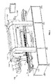
- Various product packaging machines are known in which the products are arranged in containers which are subsequently covered by a lidding film to isolate the content. Some machines are designed to form the container itself from a film (thermoforming machines such as that shown in document EP2762411A1 , for example), whereas other machines are designed to receive preformed tray-like containers (tray-sealing machines such as that shown in document US20110083810A1 , for example).
- the containers are arranged in a sealing station where they are covered with the lidding film, and the lidding film is sealed to the perimetral edge of the container, the inside of each container being isolated from the outside as a result of the container itself and the sealed lidding film covering it.
- the machine disclosed in document US20110083810A1 is suitable for providing a lidding film and a strip of tag-like film.
- Said machine comprises a bonding station for bonding the strip of film on the lidding film, means for arranging the lidding film in the bonding station, and additional means for arranging the strip of film in said bonding station.
- Said machine further comprises a sealing station, forward movement means for arranging a container in the sealing station, and means for arranging the assembly of the film formed by the lidding film and the strip of film bound in the sealing station on the container.
- the sealing station comprises sealing means for sealing the assembly of film on a perimetral edge of the container.
- the object of the invention is to provide a method for a packaging machine and a packaging machine, as described in the claims.
- a first aspect of the invention relates to a method for a packaging machine, in which at least one container with a perimetral edge is arranged in a sealing station of a packaging machine.
- the method comprises a positioning step in which a lidding film is arranged on the container in the sealing station, such that the lidding film covers the container in said sealing station, and a sealing step in which said lidding film is sealed to the perimetral edge of the container.
- an additional film narrower than the container is also added on the lidding film as a handle.
- the additional film is arranged longitudinally on the lidding film in the positioning step and sealed to the lidding film on the perimetral edge of the container in the sealing step.
- a second aspect of the invention relates to a packaging machine for sealing containers with a perimetral edge, comprising forward movement means suitable for arranging at least one container in the sealing station, and a sealing station comprising sealing means for sealing the lidding film on the perimetral edge of the container.
- the machine is suitable for adding an additional film narrower than the container on the lidding film as a handle, and further comprises means suitable for arranging a lidding film in the sealing station in a longitudinal feeding direction on a container when said container is arranged in the sealing station, and additional means suitable for adding the additional film and arranging said additional film longitudinally in the sealing station on the lidding film arranged on the container in said sealing station.
- the sealing means also seal said additional film to the lidding film on the perimetral edge of the container.
- a handle for a container is thus obtained from the additional film without having to perform operations other than those that are necessary for isolating the content of the container from the outside by means of using a lidding film covering said container, which allows productivity to be unaffected by the act of adding a handle to the container, and furthermore without the need to use an additional station or an additional machine for incorporating said handle.
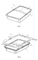
- a first aspect of the invention relates to a method for a packaging machine 100 in which at least one container 1 with a perimetral edge 10 is arranged in a sealing station 101 of the machine 100.
- the container 1 can be formed in the machine 100 itself from a forming film (in the case of a thermoforming machine), or it can comprise a tray such as that shown by way of example in Figure 1 (in the case of a tray-sealing machine such as that shown by way of example in Figure 2 ).
- the method comprises a positioning step in which a lidding film 2 is arranged on the container 1 in the sealing station 101, such that the lidding film 2 covers the container 1 in said sealing station 101, and a sealing step in which said lidding film 2 is sealed to the perimetral edge 10 of the container 1.
- the product in the container 1 is therefore isolated and protected from the outside as a result of the container 1 itself and the lidding film 2.
- an additional film 3 narrower than the container 1 and independent of the lidding film 2 is added on said lidding film 2 as a handle, the additional film 3 being arranged longitudinally on the lidding film 2 in the positioning step.
- the expression "independent of the lidding film 2" must be interpreted to mean that said films 2 and 3 are not attached to one another before being positioned inside the sealing station 101.
- the additional film 3 is sealed to the lidding film 2 on the perimetral edge 10 of the container 1 during the sealing step, preferably simultaneously with the sealing of the lidding film 2 to the perimetral edge 10 of the container 1. Since the films 2 and 3 are not previously attached to one another on the container 1 and since the additional film 3 is only sealed on the part of the lidding film 2 which is on the perimetral edge 10 of the container 1, said additional film 3 is sealed to the lidding film 2 only in two opposite sealing areas 31, as shown in Figure 3 , for example. The resulting section of additional film 3 between the two sealing areas 31 is not attached in any way to the lidding film 2 such that it can be gripped by a user. Therefore, the additional film 3 sealed to the container 1 can be used as a handle 4, and no additional step is required in the method for incorporating a handle 4 to the container 1.
- handle 4 must be understood as the areas of the additional film 3 that are sealed to the lidding film 2 (sealing areas 31) and spaced from one another, and the section of additional film 3 which is located between both areas 31 is not attached in any way to the lidding film 2, such that said section can subsequently be gripped by the end user in order to carry or handle the container 1, for example.
- the lidding film 2 and the additional film 3 are preferably fed at a rate that is substantially the same, and the tension with which the additional film 3 is fed is substantially equal to or less than the tension with which the lidding film 2 is fed.
- the tension of the additional film 3 with respect to the tension of the lidding film 2 determines the allowance of the handle 4. In other words, for one and the same container 1, less tension when feeding the additional film 3 allows obtaining a handle 4 with more allowance, the handle thus being easier to grip.
- the rigidity of the corresponding container 1 the capacity of the container 1 to deform when it is being gripped by the handle 4 influences the allowance, the greater the rigidity the less the allowance).
- the lidding film 2 and the additional film 3 also are sealed to one another in an area of attachment 32 outside the perimetral edge 10 of the container 1 during the sealing step, simultaneously with the sealing of the lidding film 2 to the perimetral edge 10 of the container 1 (although in other embodiments both sealing operations may not occur simultaneously).
- the area of attachment 32 can be separated from any sealing zone 31 of the additional film 3, or it can be an extension of at least one of said sealing areas 31.
- the lidding film 2 and the additional film 3 are preferably fed towards the sealing station 101 in a feeding direction S parallel to the longitudinal axis of the machine 100.
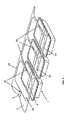
- the sealing areas 31 of the additional film 3 generated on one and the same container 1 are therefore spaced from one another in the feeding direction S, and the area of attachment 32 is arranged upstream of the container 1 in the feeding direction S if it is independent of the sealing areas 31, as shown in Figures 4 and 5 , for example, or extends upstream of the container 1 in the feeding direction S from the corresponding sealing area 31.
- Attaching both films 2 and 3 to one another through the area of attachment 32 allows the preferred embodiment of the method (and any other embodiment comprising sealing in the area of attachment 32) to comprise a collecting step in which both films 2 and 3 are collected jointly and simultaneously once sealed to the corresponding container 1 to allow arranging a new lidding film 2 and a new additional film 3 in the sealing station 101, whereby allowing simplifying the machine 100 since the same drive or collecting means can be used for collecting both films 2 and 3.
- the collecting step is performed from outside the sealing station 101, preferably also from downstream of the sealing station in the direction S, and said films 2 and 3 are collected in the feeding direction S, simultaneously arranging new films 2 and 3 in said sealing station 101 therefore being allowed.
- the collection is performed such that it allows one and the same feed rate of both films 2 and 3.
- the method comprises a cutting step during or after the sealing step in which a perimetral cut is made in the films 2 and 3 arranged on the container 1 jointly and simultaneously, thereby generating an independent pre-packed container 1 comprising a lid 5 formed by the part of the lidding film 2 which is sealed to the container 1 and separated from the rest of the lidding film 2 and a handle 4 formed by the part of the additional film 3 which is sealed to the lidding film 2 and separated from the rest of the additional film 3, as shown in the pre-packed container 1 depicted with greater detail in Figure 4 .
- the preferred embodiment of the method and any other embodiment where sealing is performed in at least one area of attachment 32 are particularly advantageous in machines 100 in which the container 1 arranged in the sealing station 101 is a tray, for example, in tray-sealing machines such as that depicted in Figure 2 by way of example.
- the perimetral edges 10 of two continuous trays have a specific gap, such that when cutting films 2 and 3 to separate each tray a surplus of lidding film 2 is generated with at least the lidding film 2 present between both trays (remnant 20), and a surplus of he additional film 3 is generated with the additional film 3 present between both trays (remnant 30).
- the remnant 30 generated between both containers 1 is independent of any other remnant 30 or any other part of the additional film 3, and as a result of sealing in the area of attachment 32, said remnant 30 and remnant 20 are attached to one another, both remnants 20 and 30 being able to be collected jointly and simultaneously in the collecting step.
- Figure 4 shows a pre-packed container 1 and remnants 20 and 30 generated after the corresponding cutting step.
- the remnant 20 is continuous and accessible from outside the sealing station 101, so it can be collected. However, the same does not happen with the remnant 30 because it is arranged inside the sealing station 101, making collection thereof difficult (it would have negative effects on subsequent packaging if not collected).
- Sealing the area of attachment 32 attaches the remnant 30 to the remnant 20, such that when collecting the remnant 20 (the lidding film 2) the remnant 30 is collected jointly and simultaneously, solving the aforementioned problem in a simple and economical manner.
- a plurality of containers 1 is arranged in the sealing station 101 one after the other and separated from one another by a specific gap, such that the lidding film 2 (and the additional film 3) can be sealed on a plurality of containers 1 simultaneously. Therefore, during the sealing step a plurality of areas of attachment 32 is generated as shown by way of example in Figure 5 , one for each container 1 to which the lidding film 2 is sealed, said areas of attachment 32 being arranged in the following manner: an area of attachment 32 further upstream in the feeding direction S, and an area of attachment 32 between every two adjacent containers 1 in the other cases (in any case, each area of attachment 32 is arranged or extends upstream in the feeding direction S of the perimetral edge 10 of a corresponding container 1).
- Figure 5 shows a plurality of continuous pre-packed containers 1 and remnants 20 and 30 generated after the corresponding cutting step (remnant 20 and remnant 30 for each container 1).
- Remnants 20 are continuous and maintain the continuity of the lidding film 2, such that they can be collected in one and the same collecting step as described in the preceding paragraph.
- the different remnants 30 are independent of one another and are hard to collect as described above, also taking into account in this case that there is a plurality of said remnants 30.
- Sealing in the areas of attachment 32 attaches all remnants 30 to corresponding remnants 20 which, as described, are continuous and maintain the continuity of the lidding film 2, such that when collecting remnants 20 (and therefore the lidding film 2), remnants 30 are collected jointly and simultaneously, solving the aforementioned problem in a simple and economical manner.
- the width of the lidding film 2 used is greater than the width of the container 1.
- This difference in widths allows the lidding film 2 to maintain continuity after the sealing and cutting steps with respect to the new lidding film 2 upstream in the feeding direction S which will be arranged in the sealing station 101, such that said continuity also enables guiding and correctly arranging a new lidding film 2 inside said sealing station 101 while at the same time the remnant 20 of the used lidding film 2 is being removed from inside the sealing station 101.
- the additional film 3, however, comprises a width less than the width of the container 1.
- the areas of attachment 32 upstream of each container 1 therefore allow clearing remnants 30 from inside the sealing station 101, and the area of attachment 32 arranged further upstream in the feeding direction S additionally allows providing continuity to the additional film 3 since it is attached to the lidding film 2 through the area of attachment 32 upstream of the last container 1, such that guiding and correctly arranging the new additional film 3 inside the sealing station 101 together with the new lidding film 2 is also enabled while at the same time remnants 20 and 30 are being cleared from the sealing station.
- a plurality of containers 1 can be also be arranged in the sealing station 101 in a parallel manner, such that there is a plurality of lines of containers 1 in the sealing station 101 parallel to one another and to the feeding direction S.
- Each line of containers 1 can be formed by a single container 1 or by a plurality of containers 1, and a lidding film 2 and an additional film 3 are fed for each line of containers 1.
- said area of attachment 32 can cover the entire width 33 of the additional film 3 or can cover a partial area (by way of point welding as shown in the drawings, for example) of said width, and even in the embodiments where a plurality of areas of attachment 32 is generated simultaneously, the areas of attachment 32 can differ from one another.
- a second aspect of the invention relates to a packaging machine 100 for sealing containers 1 with a perimetral edge 10, such as that shown by way of example in Figure 2 .
- the machine 100 comprises at least one sealing station 101 and forward movement means 103 suitable for arranging at least one container 1 in the sealing station 101, the sealing station comprising 101 sealing means 7 for sealing the lidding film 2 on the perimetral edge 10 of the container 1 ( Figure 2 does not show the lidding film 2).
- the machine 100 is suitable for adding an additional film 3 narrower than the container 1 on the lidding film 2 as a handle (not shown in Figure 2 ), and further comprises means suitable for feeding a lidding film 2 to the sealing station 101 in a longitudinal feeding direction S and arranging it on the container 1 when said container 1 is in the sealing station 101, and means suitable for adding the additional film 3 to the sealing station 101 in the feeding direction S and arranging it on the lidding film 2 arranged on the container 1 in said sealing station 101, without both films 2 and 3 being attached to one another before being arranged inside the sealing station 101.
- the sealing means 7 seal the additional film 3 to the lidding film 2 on the perimetral edge 10 of the container 1.
- the additional film 3 is sealed to the lidding film 2 in two sealing areas 31, said sealing areas being spaced from one another in the feeding direction S.
- the machine 100 comprises a reel holder 102 for storing a reel of lidding film 2 and an additional reel holder 102' for storing a reel of additional film 3 (although in other embodiments one and the same reel holder can store both reels), and guiding means 104 for guiding films 2 and 3 to the sealing station 101 (both films 2 and 3 can be guided with one and the same tool or with two different tools of the guiding means 104).
- the reel holders 102 and 102' and the guiding means 104 are suitable for feeding the lidding film 2 and the additional film 3 at a rate that is substantially the same, regardless of the diameter of the reels of the respective films 2 and 3, and for generating a tension with which the additional film 3 is fed that is substantially equal to or less than the tension with which the lidding film 2 is fed.
- the tension of the additional film 3 with respect to the tension of the lidding film 2 determines the allowance of the handle 4. In other words, for one and the same container 1, less tension when feeding the additional film 3 allows obtaining a handle 4 with more allowance, the handle thus being easier to grip.
- the sealing means 7 are suitable for sealing the lidding film 2 to the perimetral edge 10 of the container 1 and for sealing the additional film 3 to the lidding film 2 on the perimetral edge 10 of the container 1 simultaneously, and in the preferred embodiment, they are also suitable for sealing the lidding film 2 and the additional film 3 to one another in an area of attachment 32 outside the perimetral edge 10 of the container 1.
- the area of attachment 32 can be separated from a sealing area 31 of the additional film 3, or it can be an extension of at least one of said sealing areas 31.
- the sealing means 7 comprise a sealing tool 71 comprising a configuration with a shape substantially equal to the perimetral edge 10 of the container 1 for sealing the lidding film 2 to said perimetral edge 10 and the additional film 3 to the lidding film 2 on said perimetral edge 10, and an additional sealing tool 72 suitable for sealing the additional film 3 to the lidding film 2 in the area of attachment 32.
- the additional sealing tool 72 is arranged upstream of the sealing tool 71 in the feeding direction S (separated from said sealing tool 71 or as a continuation of said sealing tool 71) and is suitable for moving simultaneously with the sealing tool 71.
- the sealing tool 71 and the additional sealing tool 72 are preferably fixed solidly to each other.
- the additional sealing tool 72 can also be suitable for partially or completely attaching the width 33 of the additional film 3 to the lidding film 2.
- the machine 100 comprises cutting means 105 in the sealing station 101 suitable for making a perimetral cut in the lidding film 2 arranged on the container 1 and a cut in the part of the additional film 3 arranged on the perimetral edge 10 of the container 1 jointly and simultaneously, generating a remnant 20 of lidding film 2 and a remnant 30 of additional film 3 as a result of the cut.
- the explanation provided as regards remnants 20 and 30 in the first aspect of the invention also applies to the second aspect of the invention, so further explanation will not be given.
- the machine 100 further comprises driving means with a reel holder 106 suitable for collecting the remnant 20 of lidding film 2 and the remnant 30 of additional film 3 jointly and simultaneously, and the guiding means 104 can also guide said remnants 20 and 30 towards the reel holder 106 (the guiding means comprise at least one additional tool for this purpose).
- the driving means can be suitable for collecting remnants 20 and 30 such that they allow feeding the lidding film 2 and the additional film 3 to the sealing station 101 at a rate that is substantially the same, and generating a tension with which the additional film 3 is fed that is substantially equal to or less than the tension with which the lidding film 2 is fed. This has also been explained above in the first aspect of the invention, and further explanation will not be given.
- the machine 100 can be suitable for housing a plurality of containers 1 one after the other and separated from one another by a specific gap in the sealing station 101, the sealing means 7 of said sealing station 101 comprising a sealing tool 71 and an additional sealing tool 72 for each container 1 as shown in Figures 6 to 8 .
- Each sealing tool 71 and 72 comprises an upper part and a lower part between which the containers 1 and films 2 and 3 are arranged, the containers 1 being arranged on the lower part. Sealing and cutting are performed with the relative movement between both respective parts.
- Additional sealing tools 72 for sealing the lidding film 2 and additional film 3 to one another are arranged between every two containers 1 upstream of the sealing tool 71 in the feeding direction S, as explained for the first aspect of the invention and as shown in Figures 6 and 7 , for example.
- Figure 7 shows a bottom view of the upper part of the sealing means, which have been identified as tools 71 and 72 for the sake of clarity, although as discussed, each tool 71 and 72 comprises its respective lower part.
- the machine 100 can be suitable for housing a plurality of containers 1 in the sealing station 101 in a parallel manner, such that there is a plurality of lines of containers 1 in the sealing station 101 parallel to one another and to the feeding direction S.
- Each line of containers 1 can be formed by a single container 1 or by a plurality of containers 1, and a lidding film 2 and an additional film 3 are fed for each line of containers 1.
- the sealing means 7 are suitably configured for the pertinent embodiment, comprising as many tools 71 and 72 as required in each case.
Priority Applications (2)
| Application Number | Priority Date | Filing Date | Title |
|---|---|---|---|
| EP14382468.8A EP3023339B1 (de) | 2014-11-24 | 2014-11-24 | Ein verfahren und eine vorrichtung für verpackung |
| ES14382468.8T ES2633500T3 (es) | 2014-11-24 | 2014-11-24 | Método para una máquina envasadora, y máquina envasadora |
Applications Claiming Priority (1)
| Application Number | Priority Date | Filing Date | Title |
|---|---|---|---|
| EP14382468.8A EP3023339B1 (de) | 2014-11-24 | 2014-11-24 | Ein verfahren und eine vorrichtung für verpackung |
Publications (2)
| Publication Number | Publication Date |
|---|---|
| EP3023339A1 true EP3023339A1 (de) | 2016-05-25 |
| EP3023339B1 EP3023339B1 (de) | 2017-05-24 |
Family
ID=52021146
Family Applications (1)
| Application Number | Title | Priority Date | Filing Date |
|---|---|---|---|
| EP14382468.8A Active EP3023339B1 (de) | 2014-11-24 | 2014-11-24 | Ein verfahren und eine vorrichtung für verpackung |
Country Status (2)
| Country | Link |
|---|---|
| EP (1) | EP3023339B1 (de) |
| ES (1) | ES2633500T3 (de) |
Cited By (2)
| Publication number | Priority date | Publication date | Assignee | Title |
|---|---|---|---|---|
| EP3395702A1 (de) * | 2017-04-28 | 2018-10-31 | MULTIVAC Sepp Haggenmüller SE & Co. KG | Siegelvorrichtung |
| EP3569511A1 (de) | 2018-05-16 | 2019-11-20 | Ulma Packaging Technological Center, S.Coop. | Verpackungsverfahren und verpackungsmaschine |
Citations (7)
| Publication number | Priority date | Publication date | Assignee | Title |
|---|---|---|---|---|
| US3557516A (en) * | 1968-10-30 | 1971-01-26 | Reynolds Metals Co | Method of making a package construction |
| EP0178142A1 (de) * | 1984-10-12 | 1986-04-16 | Minnesota Mining And Manufacturing Company | Handgriff einer durch Wärme schrumpfbaren Verpackung |
| US6234230B1 (en) * | 1998-12-16 | 2001-05-22 | Cefma Company | Device for continuously applying self-adhesive handles to moving articles |
| US20110008381A1 (en) | 2007-05-18 | 2011-01-13 | Andrea Keane-Myers | Suppression of allergic inflammation by ascaris heme-binding protein (hbp) |
| US20110083810A1 (en) | 2009-10-13 | 2011-04-14 | David Lin | Container Sealing Machine for Food Packaging |
| WO2012076195A1 (en) * | 2010-12-10 | 2012-06-14 | Rev Packaging Solutions S.R.L. | Method and apparatus for packaging products in tubular net |
| EP2762411A1 (de) | 2013-02-01 | 2014-08-06 | Ulma Packaging Technological Center, S.Coop. | Tiefziehmaschine |
-
2014
- 2014-11-24 EP EP14382468.8A patent/EP3023339B1/de active Active
- 2014-11-24 ES ES14382468.8T patent/ES2633500T3/es active Active
Patent Citations (7)
| Publication number | Priority date | Publication date | Assignee | Title |
|---|---|---|---|---|
| US3557516A (en) * | 1968-10-30 | 1971-01-26 | Reynolds Metals Co | Method of making a package construction |
| EP0178142A1 (de) * | 1984-10-12 | 1986-04-16 | Minnesota Mining And Manufacturing Company | Handgriff einer durch Wärme schrumpfbaren Verpackung |
| US6234230B1 (en) * | 1998-12-16 | 2001-05-22 | Cefma Company | Device for continuously applying self-adhesive handles to moving articles |
| US20110008381A1 (en) | 2007-05-18 | 2011-01-13 | Andrea Keane-Myers | Suppression of allergic inflammation by ascaris heme-binding protein (hbp) |
| US20110083810A1 (en) | 2009-10-13 | 2011-04-14 | David Lin | Container Sealing Machine for Food Packaging |
| WO2012076195A1 (en) * | 2010-12-10 | 2012-06-14 | Rev Packaging Solutions S.R.L. | Method and apparatus for packaging products in tubular net |
| EP2762411A1 (de) | 2013-02-01 | 2014-08-06 | Ulma Packaging Technological Center, S.Coop. | Tiefziehmaschine |
Cited By (5)
| Publication number | Priority date | Publication date | Assignee | Title |
|---|---|---|---|---|
| EP3395702A1 (de) * | 2017-04-28 | 2018-10-31 | MULTIVAC Sepp Haggenmüller SE & Co. KG | Siegelvorrichtung |
| DE102017109211A1 (de) | 2017-04-28 | 2018-10-31 | Multivac Sepp Haggenmüller Se & Co. Kg | Siegelvorrichtung |
| US10906686B2 (en) | 2017-04-28 | 2021-02-02 | Multivac Sepp Haggenmüller Se & Co. Kg | Sealing device |
| EP3569511A1 (de) | 2018-05-16 | 2019-11-20 | Ulma Packaging Technological Center, S.Coop. | Verpackungsverfahren und verpackungsmaschine |
| WO2019219992A1 (es) | 2018-05-16 | 2019-11-21 | Ulma Packaging Technological Center, S.Coop. | Método y máquina de envasado |
Also Published As
| Publication number | Publication date |
|---|---|
| EP3023339B1 (de) | 2017-05-24 |
| ES2633500T3 (es) | 2017-09-21 |
Similar Documents
| Publication | Publication Date | Title |
|---|---|---|
| US20090025340A1 (en) | Method for Producing a Package and Packaging Machine | |
| EP3172136B1 (de) | Wiederverschliessbare verpackung mit handgriff, verfahren und maschine um solche verpackung herzustellen | |
| US20050252351A1 (en) | Packaging machine and method for cutting packages | |
| EP3023339B1 (de) | Ein verfahren und eine vorrichtung für verpackung | |
| KR20070084242A (ko) | 용이한 개봉을 보장하는 필름 포장용지 | |
| US8752357B2 (en) | Thermoform packaging machine and method of operating the same | |
| US20100242411A1 (en) | Method of manufacturing a package and packaging machine | |
| US9731484B2 (en) | Method and device for making tubular bags of thin plastic films by means of an ultrasound welding process | |
| US3596824A (en) | Carrier bags | |
| US20160280440A1 (en) | Thermoforming packaging machine, method and packaging | |
| EP2907760A1 (de) | Verfahren und Vorrichtung zum Vakuumverpacken eines Produkts | |
| SE455585B (sv) | Forfarande for framstellning av pasliknande forpackningsemnen | |
| EP3366594A1 (de) | Verpackungsverfahren und -maschine | |
| CN104718040B (zh) | 用于修剪轧件的装置 | |
| US11155053B2 (en) | Method for forming an opened die-cut element, particularly for forming a wrap-around box of the tray plus lid type, and a cartoning machine | |
| GB2293134A (en) | Supply of fitments on a flexible tape | |
| EP1733970B1 (de) | Verfahren und Vorrichtung zum Zuführen, Befüllen und Verpacken von Behältern | |
| EP3536426A1 (de) | Werkzeug für trennprozess | |
| NL2021278B1 (en) | Cutter blade for a packing container and a packing container | |
| KR102301095B1 (ko) | 수액용기 제조장치 | |
| KR101110985B1 (ko) | 스파우트 백 제조설비가 구비된 포장 백 제조장치 | |
| US20160318641A1 (en) | Thermoform packaging machine with 2-axis robot | |
| JP5286067B2 (ja) | 包装袋製造装置および包装袋製造方法 | |
| EP4242117A1 (de) | Steuerungsverfahren für eine verpackungsmaschine und zugehörige verpackungsmaschine | |
| EP3296217B1 (de) | Verfahren und vorrichtung zur verpackung von produkten |
Legal Events
| Date | Code | Title | Description |
|---|---|---|---|
| AK | Designated contracting states |
Kind code of ref document: A1 Designated state(s): AL AT BE BG CH CY CZ DE DK EE ES FI FR GB GR HR HU IE IS IT LI LT LU LV MC MK MT NL NO PL PT RO RS SE SI SK SM TR |
|
| AX | Request for extension of the european patent |
Extension state: BA ME |
|
| PUAI | Public reference made under article 153(3) epc to a published international application that has entered the european phase |
Free format text: ORIGINAL CODE: 0009012 |
|
| 17P | Request for examination filed |
Effective date: 20161125 |
|
| RBV | Designated contracting states (corrected) |
Designated state(s): AL AT BE BG CH CY CZ DE DK EE ES FI FR GB GR HR HU IE IS IT LI LT LU LV MC MK MT NL NO PL PT RO RS SE SI SK SM TR |
|
| GRAP | Despatch of communication of intention to grant a patent |
Free format text: ORIGINAL CODE: EPIDOSNIGR1 |
|
| INTG | Intention to grant announced |
Effective date: 20170210 |
|
| GRAS | Grant fee paid |
Free format text: ORIGINAL CODE: EPIDOSNIGR3 |
|
| GRAA | (expected) grant |
Free format text: ORIGINAL CODE: 0009210 |
|
| AK | Designated contracting states |
Kind code of ref document: B1 Designated state(s): AL AT BE BG CH CY CZ DE DK EE ES FI FR GB GR HR HU IE IS IT LI LT LU LV MC MK MT NL NO PL PT RO RS SE SI SK SM TR |
|
| REG | Reference to a national code |
Ref country code: GB Ref legal event code: FG4D |
|
| REG | Reference to a national code |
Ref country code: CH Ref legal event code: EP |
|
| REG | Reference to a national code |
Ref country code: IE Ref legal event code: FG4D |
|
| REG | Reference to a national code |
Ref country code: AT Ref legal event code: REF Ref document number: 895905 Country of ref document: AT Kind code of ref document: T Effective date: 20170615 |
|
| REG | Reference to a national code |
Ref country code: DE Ref legal event code: R096 Ref document number: 602014010093 Country of ref document: DE |
|
| REG | Reference to a national code |
Ref country code: ES Ref legal event code: FG2A Ref document number: 2633500 Country of ref document: ES Kind code of ref document: T3 Effective date: 20170921 |
|
| REG | Reference to a national code |
Ref country code: NL Ref legal event code: MP Effective date: 20170524 |
|
| REG | Reference to a national code |
Ref country code: LT Ref legal event code: MG4D |
|
| REG | Reference to a national code |
Ref country code: AT Ref legal event code: MK05 Ref document number: 895905 Country of ref document: AT Kind code of ref document: T Effective date: 20170524 |
|
| PG25 | Lapsed in a contracting state [announced via postgrant information from national office to epo] |
Ref country code: FI Free format text: LAPSE BECAUSE OF FAILURE TO SUBMIT A TRANSLATION OF THE DESCRIPTION OR TO PAY THE FEE WITHIN THE PRESCRIBED TIME-LIMIT Effective date: 20170524 Ref country code: HR Free format text: LAPSE BECAUSE OF FAILURE TO SUBMIT A TRANSLATION OF THE DESCRIPTION OR TO PAY THE FEE WITHIN THE PRESCRIBED TIME-LIMIT Effective date: 20170524 Ref country code: NO Free format text: LAPSE BECAUSE OF FAILURE TO SUBMIT A TRANSLATION OF THE DESCRIPTION OR TO PAY THE FEE WITHIN THE PRESCRIBED TIME-LIMIT Effective date: 20170824 Ref country code: AT Free format text: LAPSE BECAUSE OF FAILURE TO SUBMIT A TRANSLATION OF THE DESCRIPTION OR TO PAY THE FEE WITHIN THE PRESCRIBED TIME-LIMIT Effective date: 20170524 Ref country code: LT Free format text: LAPSE BECAUSE OF FAILURE TO SUBMIT A TRANSLATION OF THE DESCRIPTION OR TO PAY THE FEE WITHIN THE PRESCRIBED TIME-LIMIT Effective date: 20170524 |
|
| PG25 | Lapsed in a contracting state [announced via postgrant information from national office to epo] |
Ref country code: BG Free format text: LAPSE BECAUSE OF FAILURE TO SUBMIT A TRANSLATION OF THE DESCRIPTION OR TO PAY THE FEE WITHIN THE PRESCRIBED TIME-LIMIT Effective date: 20170824 Ref country code: NL Free format text: LAPSE BECAUSE OF FAILURE TO SUBMIT A TRANSLATION OF THE DESCRIPTION OR TO PAY THE FEE WITHIN THE PRESCRIBED TIME-LIMIT Effective date: 20170524 Ref country code: RS Free format text: LAPSE BECAUSE OF FAILURE TO SUBMIT A TRANSLATION OF THE DESCRIPTION OR TO PAY THE FEE WITHIN THE PRESCRIBED TIME-LIMIT Effective date: 20170524 Ref country code: SE Free format text: LAPSE BECAUSE OF FAILURE TO SUBMIT A TRANSLATION OF THE DESCRIPTION OR TO PAY THE FEE WITHIN THE PRESCRIBED TIME-LIMIT Effective date: 20170524 Ref country code: LV Free format text: LAPSE BECAUSE OF FAILURE TO SUBMIT A TRANSLATION OF THE DESCRIPTION OR TO PAY THE FEE WITHIN THE PRESCRIBED TIME-LIMIT Effective date: 20170524 Ref country code: IS Free format text: LAPSE BECAUSE OF FAILURE TO SUBMIT A TRANSLATION OF THE DESCRIPTION OR TO PAY THE FEE WITHIN THE PRESCRIBED TIME-LIMIT Effective date: 20170924 |
|
| PG25 | Lapsed in a contracting state [announced via postgrant information from national office to epo] |
Ref country code: EE Free format text: LAPSE BECAUSE OF FAILURE TO SUBMIT A TRANSLATION OF THE DESCRIPTION OR TO PAY THE FEE WITHIN THE PRESCRIBED TIME-LIMIT Effective date: 20170524 Ref country code: RO Free format text: LAPSE BECAUSE OF FAILURE TO SUBMIT A TRANSLATION OF THE DESCRIPTION OR TO PAY THE FEE WITHIN THE PRESCRIBED TIME-LIMIT Effective date: 20170524 Ref country code: CZ Free format text: LAPSE BECAUSE OF FAILURE TO SUBMIT A TRANSLATION OF THE DESCRIPTION OR TO PAY THE FEE WITHIN THE PRESCRIBED TIME-LIMIT Effective date: 20170524 Ref country code: DK Free format text: LAPSE BECAUSE OF FAILURE TO SUBMIT A TRANSLATION OF THE DESCRIPTION OR TO PAY THE FEE WITHIN THE PRESCRIBED TIME-LIMIT Effective date: 20170524 Ref country code: SK Free format text: LAPSE BECAUSE OF FAILURE TO SUBMIT A TRANSLATION OF THE DESCRIPTION OR TO PAY THE FEE WITHIN THE PRESCRIBED TIME-LIMIT Effective date: 20170524 |
|
| REG | Reference to a national code |
Ref country code: DE Ref legal event code: R097 Ref document number: 602014010093 Country of ref document: DE |
|
| PG25 | Lapsed in a contracting state [announced via postgrant information from national office to epo] |
Ref country code: PL Free format text: LAPSE BECAUSE OF FAILURE TO SUBMIT A TRANSLATION OF THE DESCRIPTION OR TO PAY THE FEE WITHIN THE PRESCRIBED TIME-LIMIT Effective date: 20170524 Ref country code: IT Free format text: LAPSE BECAUSE OF FAILURE TO SUBMIT A TRANSLATION OF THE DESCRIPTION OR TO PAY THE FEE WITHIN THE PRESCRIBED TIME-LIMIT Effective date: 20170524 Ref country code: SM Free format text: LAPSE BECAUSE OF FAILURE TO SUBMIT A TRANSLATION OF THE DESCRIPTION OR TO PAY THE FEE WITHIN THE PRESCRIBED TIME-LIMIT Effective date: 20170524 |
|
| PLBE | No opposition filed within time limit |
Free format text: ORIGINAL CODE: 0009261 |
|
| STAA | Information on the status of an ep patent application or granted ep patent |
Free format text: STATUS: NO OPPOSITION FILED WITHIN TIME LIMIT |
|
| 26N | No opposition filed |
Effective date: 20180227 |
|
| PG25 | Lapsed in a contracting state [announced via postgrant information from national office to epo] |
Ref country code: SI Free format text: LAPSE BECAUSE OF FAILURE TO SUBMIT A TRANSLATION OF THE DESCRIPTION OR TO PAY THE FEE WITHIN THE PRESCRIBED TIME-LIMIT Effective date: 20170524 |
|
| REG | Reference to a national code |
Ref country code: DE Ref legal event code: R119 Ref document number: 602014010093 Country of ref document: DE |
|
| PG25 | Lapsed in a contracting state [announced via postgrant information from national office to epo] |
Ref country code: MC Free format text: LAPSE BECAUSE OF FAILURE TO SUBMIT A TRANSLATION OF THE DESCRIPTION OR TO PAY THE FEE WITHIN THE PRESCRIBED TIME-LIMIT Effective date: 20170524 |
|
| PG25 | Lapsed in a contracting state [announced via postgrant information from national office to epo] |
Ref country code: LI Free format text: LAPSE BECAUSE OF NON-PAYMENT OF DUE FEES Effective date: 20171130 Ref country code: CH Free format text: LAPSE BECAUSE OF NON-PAYMENT OF DUE FEES Effective date: 20171130 |
|
| PG25 | Lapsed in a contracting state [announced via postgrant information from national office to epo] |
Ref country code: LU Free format text: LAPSE BECAUSE OF NON-PAYMENT OF DUE FEES Effective date: 20171124 |
|
| REG | Reference to a national code |
Ref country code: FR Ref legal event code: ST Effective date: 20180731 Ref country code: BE Ref legal event code: MM Effective date: 20171130 |
|
| REG | Reference to a national code |
Ref country code: IE Ref legal event code: MM4A |
|
| PG25 | Lapsed in a contracting state [announced via postgrant information from national office to epo] |
Ref country code: MT Free format text: LAPSE BECAUSE OF NON-PAYMENT OF DUE FEES Effective date: 20171124 |
|
| PG25 | Lapsed in a contracting state [announced via postgrant information from national office to epo] |
Ref country code: IE Free format text: LAPSE BECAUSE OF NON-PAYMENT OF DUE FEES Effective date: 20171124 Ref country code: DE Free format text: LAPSE BECAUSE OF NON-PAYMENT OF DUE FEES Effective date: 20180602 Ref country code: FR Free format text: LAPSE BECAUSE OF NON-PAYMENT OF DUE FEES Effective date: 20171130 |
|
| PG25 | Lapsed in a contracting state [announced via postgrant information from national office to epo] |
Ref country code: BE Free format text: LAPSE BECAUSE OF NON-PAYMENT OF DUE FEES Effective date: 20171130 |
|
| PG25 | Lapsed in a contracting state [announced via postgrant information from national office to epo] |
Ref country code: HU Free format text: LAPSE BECAUSE OF FAILURE TO SUBMIT A TRANSLATION OF THE DESCRIPTION OR TO PAY THE FEE WITHIN THE PRESCRIBED TIME-LIMIT; INVALID AB INITIO Effective date: 20141124 |
|
| GBPC | Gb: european patent ceased through non-payment of renewal fee |
Effective date: 20181124 |
|
| PG25 | Lapsed in a contracting state [announced via postgrant information from national office to epo] |
Ref country code: CY Free format text: LAPSE BECAUSE OF FAILURE TO SUBMIT A TRANSLATION OF THE DESCRIPTION OR TO PAY THE FEE WITHIN THE PRESCRIBED TIME-LIMIT Effective date: 20170524 |
|
| PG25 | Lapsed in a contracting state [announced via postgrant information from national office to epo] |
Ref country code: MK Free format text: LAPSE BECAUSE OF FAILURE TO SUBMIT A TRANSLATION OF THE DESCRIPTION OR TO PAY THE FEE WITHIN THE PRESCRIBED TIME-LIMIT Effective date: 20170524 |
|
| PG25 | Lapsed in a contracting state [announced via postgrant information from national office to epo] |
Ref country code: GB Free format text: LAPSE BECAUSE OF NON-PAYMENT OF DUE FEES Effective date: 20181124 |
|
| PG25 | Lapsed in a contracting state [announced via postgrant information from national office to epo] |
Ref country code: TR Free format text: LAPSE BECAUSE OF FAILURE TO SUBMIT A TRANSLATION OF THE DESCRIPTION OR TO PAY THE FEE WITHIN THE PRESCRIBED TIME-LIMIT Effective date: 20170524 |
|
| PG25 | Lapsed in a contracting state [announced via postgrant information from national office to epo] |
Ref country code: PT Free format text: LAPSE BECAUSE OF FAILURE TO SUBMIT A TRANSLATION OF THE DESCRIPTION OR TO PAY THE FEE WITHIN THE PRESCRIBED TIME-LIMIT Effective date: 20170524 |
|
| PG25 | Lapsed in a contracting state [announced via postgrant information from national office to epo] |
Ref country code: GR Free format text: LAPSE BECAUSE OF FAILURE TO SUBMIT A TRANSLATION OF THE DESCRIPTION OR TO PAY THE FEE WITHIN THE PRESCRIBED TIME-LIMIT Effective date: 20170524 |
|
| PG25 | Lapsed in a contracting state [announced via postgrant information from national office to epo] |
Ref country code: AL Free format text: LAPSE BECAUSE OF FAILURE TO SUBMIT A TRANSLATION OF THE DESCRIPTION OR TO PAY THE FEE WITHIN THE PRESCRIBED TIME-LIMIT Effective date: 20170524 |
|
| REG | Reference to a national code |
Ref country code: ES Ref legal event code: PC2A Owner name: ULMA PACKAGING, S.COOP. Effective date: 20230216 |
|
| PGFP | Annual fee paid to national office [announced via postgrant information from national office to epo] |
Ref country code: ES Payment date: 20231201 Year of fee payment: 10 |