EP3022461B1 - Schwungräder zur energiespeicherung und verfahren zur herstellung davon - Google Patents
Schwungräder zur energiespeicherung und verfahren zur herstellung davon Download PDFInfo
- Publication number
- EP3022461B1 EP3022461B1 EP14742333.9A EP14742333A EP3022461B1 EP 3022461 B1 EP3022461 B1 EP 3022461B1 EP 14742333 A EP14742333 A EP 14742333A EP 3022461 B1 EP3022461 B1 EP 3022461B1
- Authority
- EP
- European Patent Office
- Prior art keywords
- ring
- rotor
- assembly
- rotor support
- support
- Prior art date
- Legal status (The legal status is an assumption and is not a legal conclusion. Google has not performed a legal analysis and makes no representation as to the accuracy of the status listed.)
- Active
Links
- 238000000034 method Methods 0.000 title claims description 12
- 238000004519 manufacturing process Methods 0.000 title claims description 6
- 238000004146 energy storage Methods 0.000 title description 3
- 239000011159 matrix material Substances 0.000 claims description 8
- 230000008878 coupling Effects 0.000 claims description 4
- 238000010168 coupling process Methods 0.000 claims description 4
- 238000005859 coupling reaction Methods 0.000 claims description 4
- 239000000463 material Substances 0.000 description 8
- 239000002131 composite material Substances 0.000 description 7
- 239000007767 bonding agent Substances 0.000 description 6
- OKTJSMMVPCPJKN-UHFFFAOYSA-N Carbon Chemical compound [C] OKTJSMMVPCPJKN-UHFFFAOYSA-N 0.000 description 5
- 229910052799 carbon Inorganic materials 0.000 description 5
- 239000011347 resin Substances 0.000 description 5
- 229920005989 resin Polymers 0.000 description 5
- 239000003365 glass fiber Substances 0.000 description 4
- 239000000314 lubricant Substances 0.000 description 4
- 230000000712 assembly Effects 0.000 description 3
- 238000000429 assembly Methods 0.000 description 3
- 238000005336 cracking Methods 0.000 description 2
- 108700028490 CAP protocol 2 Proteins 0.000 description 1
- 239000011248 coating agent Substances 0.000 description 1
- 238000000576 coating method Methods 0.000 description 1
- 238000010276 construction Methods 0.000 description 1
- 230000001419 dependent effect Effects 0.000 description 1
- 230000005489 elastic deformation Effects 0.000 description 1
- 239000000835 fiber Substances 0.000 description 1
- 239000011521 glass Substances 0.000 description 1
- 230000000977 initiatory effect Effects 0.000 description 1
- 238000005461 lubrication Methods 0.000 description 1
- 239000000696 magnetic material Substances 0.000 description 1
- 239000006249 magnetic particle Substances 0.000 description 1
- 239000000203 mixture Substances 0.000 description 1
- 239000002245 particle Substances 0.000 description 1
- 230000000717 retained effect Effects 0.000 description 1
- 239000011435 rock Substances 0.000 description 1
- 238000000926 separation method Methods 0.000 description 1
- 238000010008 shearing Methods 0.000 description 1
- 238000003892 spreading Methods 0.000 description 1
- 238000003860 storage Methods 0.000 description 1
- 239000011800 void material Substances 0.000 description 1
Images

Classifications
-
- F—MECHANICAL ENGINEERING; LIGHTING; HEATING; WEAPONS; BLASTING
- F16—ENGINEERING ELEMENTS AND UNITS; GENERAL MEASURES FOR PRODUCING AND MAINTAINING EFFECTIVE FUNCTIONING OF MACHINES OR INSTALLATIONS; THERMAL INSULATION IN GENERAL
- F16F—SPRINGS; SHOCK-ABSORBERS; MEANS FOR DAMPING VIBRATION
- F16F15/00—Suppression of vibrations in systems; Means or arrangements for avoiding or reducing out-of-balance forces, e.g. due to motion
- F16F15/30—Flywheels
- F16F15/305—Flywheels made of plastics, e.g. fibre-reinforced plastics [FRP], i.e. characterised by their special construction from such materials
-
- F—MECHANICAL ENGINEERING; LIGHTING; HEATING; WEAPONS; BLASTING
- F16—ENGINEERING ELEMENTS AND UNITS; GENERAL MEASURES FOR PRODUCING AND MAINTAINING EFFECTIVE FUNCTIONING OF MACHINES OR INSTALLATIONS; THERMAL INSULATION IN GENERAL
- F16F—SPRINGS; SHOCK-ABSORBERS; MEANS FOR DAMPING VIBRATION
- F16F15/00—Suppression of vibrations in systems; Means or arrangements for avoiding or reducing out-of-balance forces, e.g. due to motion
- F16F15/30—Flywheels
- F16F15/315—Flywheels characterised by their supporting arrangement, e.g. mountings, cages, securing inertia member to shaft
- F16F15/3153—Securing inertia members to the shafts
-
- B—PERFORMING OPERATIONS; TRANSPORTING
- B60—VEHICLES IN GENERAL
- B60K—ARRANGEMENT OR MOUNTING OF PROPULSION UNITS OR OF TRANSMISSIONS IN VEHICLES; ARRANGEMENT OR MOUNTING OF PLURAL DIVERSE PRIME-MOVERS IN VEHICLES; AUXILIARY DRIVES FOR VEHICLES; INSTRUMENTATION OR DASHBOARDS FOR VEHICLES; ARRANGEMENTS IN CONNECTION WITH COOLING, AIR INTAKE, GAS EXHAUST OR FUEL SUPPLY OF PROPULSION UNITS IN VEHICLES
- B60K6/00—Arrangement or mounting of plural diverse prime-movers for mutual or common propulsion, e.g. hybrid propulsion systems comprising electric motors and internal combustion engines ; Control systems therefor, i.e. systems controlling two or more prime movers, or controlling one of these prime movers and any of the transmission, drive or drive units Informative references: mechanical gearings with secondary electric drive F16H3/72; arrangements for handling mechanical energy structurally associated with the dynamo-electric machine H02K7/00; machines comprising structurally interrelated motor and generator parts H02K51/00; dynamo-electric machines not otherwise provided for in H02K see H02K99/00
- B60K6/08—Prime-movers comprising combustion engines and mechanical or fluid energy storing means
- B60K6/10—Prime-movers comprising combustion engines and mechanical or fluid energy storing means by means of a chargeable mechanical accumulator, e.g. flywheel
- B60K6/105—Prime-movers comprising combustion engines and mechanical or fluid energy storing means by means of a chargeable mechanical accumulator, e.g. flywheel the accumulator being a flywheel
-
- Y—GENERAL TAGGING OF NEW TECHNOLOGICAL DEVELOPMENTS; GENERAL TAGGING OF CROSS-SECTIONAL TECHNOLOGIES SPANNING OVER SEVERAL SECTIONS OF THE IPC; TECHNICAL SUBJECTS COVERED BY FORMER USPC CROSS-REFERENCE ART COLLECTIONS [XRACs] AND DIGESTS
- Y02—TECHNOLOGIES OR APPLICATIONS FOR MITIGATION OR ADAPTATION AGAINST CLIMATE CHANGE
- Y02E—REDUCTION OF GREENHOUSE GAS [GHG] EMISSIONS, RELATED TO ENERGY GENERATION, TRANSMISSION OR DISTRIBUTION
- Y02E60/00—Enabling technologies; Technologies with a potential or indirect contribution to GHG emissions mitigation
- Y02E60/16—Mechanical energy storage, e.g. flywheels or pressurised fluids
-
- Y—GENERAL TAGGING OF NEW TECHNOLOGICAL DEVELOPMENTS; GENERAL TAGGING OF CROSS-SECTIONAL TECHNOLOGIES SPANNING OVER SEVERAL SECTIONS OF THE IPC; TECHNICAL SUBJECTS COVERED BY FORMER USPC CROSS-REFERENCE ART COLLECTIONS [XRACs] AND DIGESTS
- Y02—TECHNOLOGIES OR APPLICATIONS FOR MITIGATION OR ADAPTATION AGAINST CLIMATE CHANGE
- Y02T—CLIMATE CHANGE MITIGATION TECHNOLOGIES RELATED TO TRANSPORTATION
- Y02T10/00—Road transport of goods or passengers
- Y02T10/60—Other road transportation technologies with climate change mitigation effect
- Y02T10/62—Hybrid vehicles
Definitions
- the present invention relates to flywheels used for kinetic energy storage and more particularly the construction of such flywheels using composite materials.
- flywheels it is well known to use flywheels to store mechanical kinetic energy.
- the amount of energy stored depends on the mass of the flywheel and its speed of rotation.
- the kinetic energy of the flywheel is proportional to the square of its angular velocity.
- the amount of energy that may be stored in a given flywheel is dependent upon the robustness of the flywheel assembly and how it responds to the stresses experienced at high rotational speeds.
- flywheel assemblies from materials which are of low density and high specific strength.
- energy storage flywheel assemblies need to operate at extremely high speeds, greater than 10,000 rev./min. or even more than 50,000 or 100,000 rev./min. Accordingly, there is considerable demand for flywheel assemblies that are able to operate at speeds of these orders.
- US4,341,001 discloses a flywheel assembly comprising a metallic hub.
- the composite fibre rim is wound directly onto the hub.
- WO-A-96/15391 relates to a flywheel having a hollow shaft part which is interconnected with an annular body so as to allow radial expansion of the latter under the influence of centrifugal forces.
- GB-A-2469657 describes a flywheel assembly which is suitable for use as a compact power storage device.
- the present invention is directed at a flywheel assembly having a longitudinal axis and comprising an annular rotor and a rotor support for coupling the rotor to an axial shaft, wherein:
- the ring has a greater elasticity than the rotor support in the circumferential direction.
- the presence of the intermediate ring formed of a composite material assists the fabrication of the assembly and increases its durability by providing a suitable interface between the rotor and the rotor support.
- the fibres of the ring may comprise at least one of glass fibres, basalt rock fibres and low specific modulus carbon fibres.
- the ring has a greater elasticity than the rotor in the circumferential direction which allows it to be press fitted into the inner diameter of the rotor. Furthermore, it may also have a greater elasticity than the rotor support in the circumferential direction, so that it can be press fitted onto the outer circumference of the rotor support.
- the rotor support defines a substantially frusto-conical inner surface, which is rotationally symmetrical about its longitudinal axis.
- the angle defined by the frusto-conical inner surface with respect to a plane perpendicular to its longitudinal axis is selected so as to substantially strain match the rotor support with the ring. This ensures the integrity of the rotor support and ring assembly when subjected to centrifugal forces.
- the outer circumferential surface of the ring may have a chamfer to assist fitting of the ring into the rotor.
- the chamfer may define a lead in angle of no greater than around 15° with respect to the longitudinal axis of the ring.
- the rotor support and the ring may be configured such that an imaginary surface defined by outwardly projecting the frusto-conical inner surface of the rotor support extends through the ring from its inner circumferential surface to meet an outer cylindrical surface of the ring.
- the outer circumferential surface of the rotor support and/or the inner circumferential surface of the ring may have a chamfer to assist fitting of the rotor support into the ring.
- the or each chamfer may define a lead in angle of no greater than around 15° with respect to the longitudinal axis of the rotor support. This serves to avoid shearing of the corners of the ring as the end cap is press fitted into it.
- the assembly may also include an inner annulus mounted on an inwardly facing surface of the rotor.
- the inner annulus may include particles of magnetic material to enable the assembly to be magnetically coupled to a stator.
- the outer circumferential surface of the inner annulus and/or the inner circumferential surface of the rotor may have a chamfer to assist fitting of the annulus into the rotor.
- the or each chamfer may define a lead in angle of no greater than around 15° with respect to the longitudinal axis of the rotor.
- a volume defined by the inner circumferential, cylindrical surface of the rotor, the chamfer of the rotor support and the chamfer of the inner annulus may be substantially filled with a bonding material. Otherwise, the presence of a void at this location will reduce the ability of the assembly to withstand high centrifugal forces.
- the bonding material may be a resin material, for example.
- the edge at each end of the inner circumferential surface of the inner annulus may have a chamfer which defines an angle in the range 20 to 60° (or more preferably in the range 50 to 55°) with respect to that surface, to avoid cracking of these edges at high rotational speeds.
- the invention is also directed at a method of manufacturing a flywheel assembly having a longitudinal axis and comprising an annular rotor, a rotor support for coupling the rotor to an axial support shaft, and a ring, wherein the rotor and the ring comprise fibres in a matrix material, the ring is mounted on the outer circumference of the rotor support, the rotor is mounted on the outer circumference of the ring, and the rotor, rotor support and ring each have longitudinal axes which are coincident with the longitudinal axis of the assembly.
- the method comprises press-fitting the rotor support into the ring, wherein the ring has a greater elasticity than the rotor support in the circumferential direction.
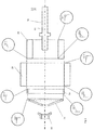
- Figure 1 illustrates a flywheel assembly 70 according to an embodiment of the present invention. It includes a rotor assembly having an annular outer rotor portion 26 and an inner annular rotor portion or annulus 66.
- the outer rotor 26 is formed of a composite material comprising unidirectional filaments of carbon fibres in a matrix of a resin material.
- the inner annulus 66 is formed of unidirectional filaments of glass fibre in a matrix formed of a mixture of resin and magnetic particles.
- the rotor assembly is carried by a rotor support in the form of a hub or end cap 74.
- a ring 84 is provided between the end cap and rotor assembly in the radial direction, with the interfaces between the ring and the end cap and rotor assembly, respectively, overlapping in the axial direction.
- the interface between the ring and the rotor entirely overlaps the interface between the ring and the end cap, in the axial direction.
- the end cap is generally conical in shape. Its outer circumference carries the ring 84 which is in turn attached to the outer rotor 26, on its inner cylindrical surface.
- the end cap extends outwardly in an axial direction from the rotor assembly and has a central circular opening 68.
- a central shaft 76 extends through the opening 68 in the end cap.
- the shaft includes a circumferentially extending flange 88.
- the end cap is retained against the flange 88 by a clamping nut 86 which is threaded onto the shaft 76.
- An anti-fretting shim 64 is provided between the nut 86 and the end cap 74.
- the shaft is supported for rotation about a longitudinal axis 81 of the flywheel assembly by a pair of bearings 90 and 92.
- the bearings are in turn supported by a containment (not shown) for the flywheel assembly.
- the rotor assembly is rotatable about an electrical motor generator stator 94 carried by the containment.
- a flywheel to be used to store energy in a vehicle may have an outer diameter of around 350mm, with the inner diameter of the outer rotor being around 290mm and the inner diameter of the inner annulus around 250mm, for example.
- the end cap 74, the ring 84, the outer rotor 26 and the inner annulus 66 are press fitted together.
- the components to be press fitted together are heated to around 60-70°C prior to the press fitting process.
- Each of these press fitted components is formed of a composite material.
- the overlaps in the radial direction between press fitted surfaces to achieve the desired interference fits maybe somewhat larger than those typically used with metallic components.
- the difference in the diameters of the inner and outer surfaces may be of the order of 0.25 mm to 0.85 mm.
- the components are bonded together to further increase the strength of the assembly.
- a resin coating is applied to the components to act as a lubricant during assembly which is then cured to produce a bond between the components.
- a resin for example Hysol® EA 9394 as manufactured by Henkel Corporation, may be used as the lubricant and bonding agent.
- the shaft 76 is inserted through the central opening 68 of the end cap.
- the end cap is secured in place on the shaft by the clamping nut 86.
- the outer circumference of the end cap is then machined as it is rotated about the longitudinal axis 81 of the assembly and shaft.
- the end cap 74 is precisely machined to the desired size.
- the glass fibre hoop wound ring 84 is then press fitted over the outer cylindrical surface of the end cap 74. This process is assisted by the bonding agent acting as a lubricant and provision of 15 degree lead in angles in the form of chamfers on the outer circumferential surface of the end cap and the inner circumferential surface of the ring. In this way, the two components can be fitted together without damage.
- the end cap and glass ring combination is then pressed into the outer carbon hoop wound rotor 26. Again, this is assisted by the lubrication of a bonding agent and 15 degree lead in angles on the outer circumferential surface of the ring 84 and the inner cylindrical surface of the rotor 26. Then, the inner hoop wound magnetic composite annulus 66 is pressed into the carbon outer rotor 26, once again employing the bonding agent as a lubricant and assisted by 15 degree lead in angles on the outer circumferential surface of the annulus and the inner cylindrical surface of the rotor.
- the components After press fitting, the components are heated to cure the bonding agent.
- the Chamfers are defined at each end of the inner cylindrical surface of the inner annulus 66.
- the chamfers preferably define angles with respect to the longitudinal axis 81 of at least 20 degrees, more preferably 20-60 degrees, and more preferably still 50-55 degrees, to avoid cracking of the edge at high rotational speeds.
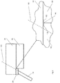
- FIG. 3 An enlarged cross-sectional view of the rotor assembly shown in Figures 1 and 2 is illustrated in Figure 3 .
- Dashed line 160 is an imaginary line projecting the inner conical surface of the end cap 74 in an outward direction through the ring 84 and rotor 26.
- Figure 3 also includes a further enlarged view of the location where this line intersects with the interface between the ring and the rotor.
- chamfers labelled 100 and 102, respectively in Figure 3
- a volume 98 is defined between the outer rotor 26, the ring 84 and the annulus 66.
- the assembly should be configured such that the projected line 160 intersects with the interface between the ring 84 and the outer rotor 26 at a location outside the volume 98. Furthermore, it is desirable to space this intersection from the volume 98, and the greater the spacing the better, subject to other configuration requirements.
- the volume is filled with a bonding agent during the assembly process to ensure that the full widths of the ring 84 and annulus 66 are supported by the outer rotor 26.
- the rotor support or end cap 74 has a conical configuration such that it is strain matched with the surrounding ring 84. Its elastic deformation during rotation therefore substantially matches that of the ring to avoid separation during rotation at high speeds.
- the angle defined by the body of the rotor support relative to a plane perpendicular to its axis of rotation is preferably in the range 17-26 degrees, and more preferably around 20 degrees.
- the ring 84 acts as a load-spreading intermediate member. It is tough enough to support the outer edge of the end cap. This avoids the end cap digging into or significantly fretting the surface of the outer rotor 26 and forming stress initiation points.
- a glass fibre-based composite may be used for the ring, for example.
- the ring is according to the invention formed of a material having a greater circumferential (hoop) elasticity than the material of the end cap, and also preferably greater than that of the material of the outer rotor. This allows the ring to be press fitted (expanded) onto the end cap and then press fitted into the carbon rotor 26.
- the ring preferably has a higher radial compressive strength than the outer rotor and a lower radial compressive strength than the end cap.
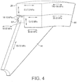
- Figure 4 includes indication of strength values for the rotor 26, annulus 66, ring 84 and end cap 74 according to one embodiment of the invention.
- the hoop tensile strength of the outer rotor 26 in this embodiment is relatively high, around 180 to 195MPa so that it can withstand the loads experienced during rotation at high speed.
- the hoop tensile strength of the ring 84 is relatively low (around 50 to 60MPa), and is similar to the hoop strength of the end cap (around 45 to 55MPa).
- the elasticity of the ring 84 in the circumferential direction is greater than that of both the outer rotor and the end cap. This facilitates the press fitting of the ring onto the end cap, and in turn the press fitting of the ring and end cap combination into the rotor.
- the radial (and axial) transverse compressive strength of the ring (14 to 16MPa) is greater than that of the rotor (6.5 to 7.5MPa), but less than the tensile strength of the end cap (60 to 70MPa) in the radial direction.
- the ring is therefore tougher than the rotor in the radial direction, and prevents the much harder end cap perimeter digging into and damaging the relatively soft rotor during assembly.
- the transverse compressive strengths of the rotor and inner annulus in the axial direction are relatively low (6.5 to 7.5MPa and 13 to 15MPa, respectively).
- the hoop tensile strength of the inner annulus is lower than that of the outer rotor, at around 33 to 35MPa.
Landscapes
- Engineering & Computer Science (AREA)
- General Engineering & Computer Science (AREA)
- Physics & Mathematics (AREA)
- Acoustics & Sound (AREA)
- Aviation & Aerospace Engineering (AREA)
- Mechanical Engineering (AREA)
- Connection Of Motors, Electrical Generators, Mechanical Devices, And The Like (AREA)
- Manufacture Of Motors, Generators (AREA)
- Rolls And Other Rotary Bodies (AREA)
- Braking Arrangements (AREA)
Claims (15)
- Schwungradanordnung (70) mit einer Längsachse (81) und umfassend einen ringförmigen Rotor (26) und eine Rotorhalterung (74) zum Koppeln des Rotors mit einer Axialwelle (76), wobei:der Rotor Fasern in einem Matrixmaterial umfasst, undein Ring (84), der Fasern in einem Matrixmaterial umfasst, an dem Außenumfang der Rotorhalterung angebracht ist und der Rotor an dem Außenumfang des Rings angebracht ist,der Rotor, die Rotorhalterung und der Ring jeweils Längsachsen aufweisen, die mit der Längsachse der Anordnung koinzident sind,dadurch gekennzeichnet, dassder Ring in der Umfangsrichtung eine größere Elastizität als die Rotorhalterung aufweist.
- Anordnung nach Anspruch 1, wobei der Ring in der Umgangsrichtung eine größere Elastizität als der Rotor aufweist.
- Anordnung nach Anspruch 1 oder Anspruch 2, wobei der Ring (84) an der äußersten Umfangsfläche der Rotorhalterung (74) angebracht ist.
- Anordnung nach einem der vorhergehenden Ansprüche, wobei die Rotorhalterung (74) in den Ring (84) eingepresst ist.
- Anordnung nach einem der vorhergehenden Ansprüche, wobei der Ring (84) in den Rotor (26) eingepresst ist.
- Anordnung nach einem der vorhergehenden Ansprüche, wobei sich die Schnittfläche zwischen der Rotorhalterung (74) und dem Ring (64) mit einer Transversalebene schneidet, die sich ebenfalls mit der Schnittfläche zwischen dem Ring und dem Rotor schneidet.
- Anordnung nach einem der vorhergehenden Ansprüche, wobei der Ring (84) eine größere radiale Druckfestigkeit aufweist als der Rotor (26).
- Anordnung nach einem der vorhergehenden Ansprüche, wobei der Ring (84) eine geringere radiale Druckfestigkeit aufweist als die Rotorhalterung (74) .
- Anordnung nach einem der vorhergehenden Ansprüche, wobei die Rotorhalterung (74) eine im Wesentlichen kegelstumpfförmige Innenfläche definiert, die um ihre Längsachse rotationssymmetrisch ist, und wobei der Winkel, der durch die kegelstumpfförmige Innenfläche der Rotorhalterung in Bezug auf eine Ebene senkrecht zu ihrer Längsachse (81) definiert ist, derart ausgewählt ist, dass die Beanspruchung der Rotorhalterung (74) mit der des Rings (84) im Wesentlichen übereinstimmt.
- Anordnung nach Anspruch 9, wobei die Außenumfangsfläche des Rings (84) eine zylindrische Fläche definiert, und die Rotorhalterung (74) und der Ring derart ausgestaltet sind, dass sich eine imaginäre Fläche, die durch ein Projizieren der kegelstumpfförmigen Innenfläche der Rotorhalterung nach außen definiert ist, von seiner Innenumfangsfläche durch den Ring erstreckt, um mit der zylindrischen Außenfläche des Rings zusammenzutreffen.
- Verfahren zum Herstellen einer Schwungradanordnung (70) mit einer Längsachse (81), wobei die Anordnung einen ringförmigen Rotor (26), eine Rotorhalterung (74) zum Koppeln des Rotors mit einer Axialstützwelle (76) und einen Ring (84) umfasst,wobei der Rotor und der Ring Fasern in einem Matrixmaterial umfassen, wobei der Ring an dem Außenumfang der Rotorhalterung angebracht ist, wobei der Rotor an dem Außenumfang des Rings angebracht ist, und wobei der Rotor, die Rotorhalterung und der Ring jeweils Längsachsen aufweisen, die mit der Längsachse der Anordnung koinzident sind,dadurch gekennzeichnet, dassdas Verfahren umfasst:
Einpressen der Rotorhalterung in den Ring, wobei der Ring in der Umgangsrichtung eine größere Elastizität als die Rotorhalterung aufweist. - Verfahren nach Anspruch 11, wobei die äußerste Umfangsfläche der Rotorhalterung (74) in den Ring (84) eingepresst wird.
- Verfahren nach Anspruch 11 oder Anspruch 12, umfassend Einpressen des Rings (84) in den Rotor (26) .
- Verfahren nach Anspruch 13, wobei die Rotorhalterung (74) in den Ring (84) eingepresst wird und anschließend der Ring in den Rotor eingepresst wird.
- Verfahren nach einem der Ansprüche 11 bis 14, wobei sich die Schnittfläche zwischen der Rotorhalterung (74) und dem Ring (84) mit einer Transversalebene schneidet, die sich ebenfalls mit der Schnittfläche zwischen dem Ring und dem Rotor (26) schneidet.
Applications Claiming Priority (2)
| Application Number | Priority Date | Filing Date | Title |
|---|---|---|---|
| GB1312927.5A GB2504217B (en) | 2013-07-19 | 2013-07-19 | Flywheels for energy storage and methods of manufacture thereof |
| PCT/GB2014/052204 WO2015008088A1 (en) | 2013-07-19 | 2014-07-18 | Flywheels for energy storage and methods of manufacture thereof |
Publications (2)
| Publication Number | Publication Date |
|---|---|
| EP3022461A1 EP3022461A1 (de) | 2016-05-25 |
| EP3022461B1 true EP3022461B1 (de) | 2019-05-01 |
Family
ID=49118975
Family Applications (1)
| Application Number | Title | Priority Date | Filing Date |
|---|---|---|---|
| EP14742333.9A Active EP3022461B1 (de) | 2013-07-19 | 2014-07-18 | Schwungräder zur energiespeicherung und verfahren zur herstellung davon |
Country Status (7)
| Country | Link |
|---|---|
| US (1) | US10012289B2 (de) |
| EP (1) | EP3022461B1 (de) |
| JP (1) | JP6492074B2 (de) |
| CN (1) | CN105531503B (de) |
| CA (1) | CA2916096A1 (de) |
| GB (1) | GB2504217B (de) |
| WO (1) | WO2015008088A1 (de) |
Families Citing this family (5)
| Publication number | Priority date | Publication date | Assignee | Title |
|---|---|---|---|---|
| US10432061B2 (en) | 2013-07-19 | 2019-10-01 | Gkn Hybrid Power Limited | Flywheel assembly |
| GB2572351B (en) * | 2018-03-27 | 2020-08-26 | Perpetuum Ltd | An electromechanical generator for converting mechanical vibrational energy into electrical energy |
| US11303186B2 (en) | 2019-09-20 | 2022-04-12 | Helix Power Corporation | Stator cooling for flywheel energy storage system |
| US11146131B2 (en) * | 2019-09-20 | 2021-10-12 | Helix Power Corporation | Composite rotor for flywheel energy storage system |
| US11143277B2 (en) | 2019-09-20 | 2021-10-12 | Helix Power Corporation | Rotor hub for flywheel energy storage system |
Family Cites Families (39)
| Publication number | Priority date | Publication date | Assignee | Title |
|---|---|---|---|---|
| US3788162A (en) | 1972-05-31 | 1974-01-29 | Univ Johns Hopkins | Pseudo-isotropic filament disk structures |
| JPS5833408B2 (ja) * | 1975-07-21 | 1983-07-19 | 東レ株式会社 | コウソクカイテンタイ |
| US4207778A (en) | 1976-07-19 | 1980-06-17 | General Electric Company | Reinforced cross-ply composite flywheel and method for making same |
| US4341001A (en) | 1978-09-13 | 1982-07-27 | U.S. Flywheels, Inc. | Hub for use in flywheels for kinetic energy storage |
| US4266442A (en) | 1979-04-25 | 1981-05-12 | General Electric Company | Flywheel including a cross-ply composite core and a relatively thick composite rim |
| JPS55157734A (en) * | 1979-05-28 | 1980-12-08 | Sanwa Denki Kk | Flywheel device of projector |
| GB8328295D0 (en) | 1983-10-22 | 1983-11-23 | British Petroleum Co Plc | Energy storage flywheels |
| JPS60201139A (ja) * | 1984-03-26 | 1985-10-11 | Hitachi Ltd | フライホイ−ル |
| JPS6131739A (ja) * | 1984-07-23 | 1986-02-14 | Hitachi Ltd | フライホイ−ル |
| JPS6335142A (ja) * | 1986-07-29 | 1988-02-15 | 三菱電機株式会社 | フライホイ−ル電源装置 |
| DK70792A (da) | 1992-05-27 | 1993-11-28 | Risoe Forskningscenter | Svinghjulsindretning |
| US5628232A (en) | 1994-01-14 | 1997-05-13 | Rosen Motors Lp | Flywheel rotor with conical hub and methods of manufacture therefor |
| BR9408005A (pt) * | 1993-11-08 | 1996-12-03 | Rosen Motors Lp | Sistema de volante para armazenagem móvel de energia |
| RU2083371C1 (ru) | 1994-04-28 | 1997-07-10 | Акционерное общество "Центр перспективных разработок" Акционерного общества "Центральный научно-исследовательский институт специального машиностроения | Несущая труба-оболочка из композиционных материалов, способ и оправка для ее изготовления |
| US5946979A (en) * | 1994-11-16 | 1999-09-07 | Forskningscenter Riso | Flywheel |
| EP0791146B1 (de) * | 1994-11-16 | 2000-02-09 | Forskningscenter Riso | Ein massenschwungrad |
| JP3697293B2 (ja) * | 1995-07-31 | 2005-09-21 | 石川島播磨重工業株式会社 | フライホイール |
| US5816114A (en) * | 1995-12-06 | 1998-10-06 | Hughes Electronics Corporation | High speed flywheel |
| JPH09303485A (ja) * | 1996-05-14 | 1997-11-25 | Chubu Electric Power Co Inc | フライホイール |
| US5778736A (en) | 1996-06-12 | 1998-07-14 | Dow-United Technologies Composite Products, Inc. | Spiral woven composite flywheel rim |
| US5784926A (en) | 1996-08-27 | 1998-07-28 | Dow-United Technologies Composite Products, Inc. | Integral composite flywheel rim and hub |
| US6122993A (en) * | 1998-01-26 | 2000-09-26 | Alliedsignal Inc. | Isotropic energy storage flywheel rotor |
| JP2000055134A (ja) * | 1998-08-06 | 2000-02-22 | Fuji Heavy Ind Ltd | 複合材フライホイール装置 |
| EP1077335A1 (de) * | 1999-08-19 | 2001-02-21 | Toray Composites (America), Inc. | Schwungradbefestigung |
| US6508145B1 (en) * | 1999-10-12 | 2003-01-21 | Toray Composites (America), Inc. | Press-fit multi-ring composite flywheel rim |
| DE19961643A1 (de) * | 1999-12-21 | 2001-06-28 | Canders Wolf R | Schwungrad mit Speichern von Rotationsenergie |
| JP2002010533A (ja) * | 2000-06-21 | 2002-01-11 | Mitsubishi Rayon Co Ltd | 繊維強化プラスチック製ロータ並びにフライホイールバッテリー装置およびその使用方法 |
| US7080573B2 (en) | 2000-10-20 | 2006-07-25 | Toray Composites (America), Inc. | Hybrid composite flywheel rim and its manufacturing method |
| US20100018344A1 (en) * | 2008-07-28 | 2010-01-28 | Ward Spears | Composite Hub for High Energy-Density Flywheel |
| US9267570B2 (en) * | 2008-07-28 | 2016-02-23 | Beacon Power, Llc | Advanced flywheel hub and method |
| GB2462671B (en) * | 2008-08-18 | 2010-12-15 | Williams Hybrid Power Ltd | Flywheel assembly with flexible coupling to enhance safety during flywheel failure |
| GB2469657B (en) * | 2009-04-22 | 2013-09-25 | Williams Hybrid Power Ltd | Flywheel assembly |
| US9673680B2 (en) * | 2011-11-13 | 2017-06-06 | Rotonix Hong Kong Limited | Electromechanical flywheels |
| EP2766632B1 (de) * | 2011-12-31 | 2017-04-12 | Rotonix Hong Kong Limited | Rückhaltesystem für ein elektromechanisches schwungrad |
| KR20140136425A (ko) * | 2012-03-15 | 2014-11-28 | 로테너지 홀딩스, 엘티디 | 안전 특성을 갖는 전자 기계식 플라이휠 |
| JP2014064346A (ja) * | 2012-09-20 | 2014-04-10 | Seiko Epson Corp | 電気機械装置、ロボット及び移動体 |
| US20140265674A1 (en) * | 2013-03-12 | 2014-09-18 | Rotonix Usa, Inc. | Electromechanical flywheel with safety features |
| US10432061B2 (en) * | 2013-07-19 | 2019-10-01 | Gkn Hybrid Power Limited | Flywheel assembly |
| GB2504218B (en) * | 2013-07-19 | 2016-09-14 | Gkn Hybrid Power Ltd | Flywheels for energy storage and methods of manufacture thereof |
-
2013
- 2013-07-19 GB GB1312927.5A patent/GB2504217B/en active Active
-
2014
- 2014-07-18 US US14/905,975 patent/US10012289B2/en active Active
- 2014-07-18 EP EP14742333.9A patent/EP3022461B1/de active Active
- 2014-07-18 WO PCT/GB2014/052204 patent/WO2015008088A1/en active Application Filing
- 2014-07-18 CA CA2916096A patent/CA2916096A1/en not_active Abandoned
- 2014-07-18 JP JP2016526705A patent/JP6492074B2/ja active Active
- 2014-07-18 CN CN201480040894.5A patent/CN105531503B/zh active Active
Non-Patent Citations (1)
| Title |
|---|
| None * |
Also Published As
| Publication number | Publication date |
|---|---|
| US20160169323A1 (en) | 2016-06-16 |
| WO2015008088A1 (en) | 2015-01-22 |
| CA2916096A1 (en) | 2015-01-22 |
| CN105531503B (zh) | 2017-11-07 |
| US10012289B2 (en) | 2018-07-03 |
| JP2016525335A (ja) | 2016-08-22 |
| JP6492074B2 (ja) | 2019-03-27 |
| GB2504217A (en) | 2014-01-22 |
| GB2504217B (en) | 2016-09-14 |
| CN105531503A (zh) | 2016-04-27 |
| EP3022461A1 (de) | 2016-05-25 |
| GB201312927D0 (en) | 2013-09-04 |
Similar Documents
| Publication | Publication Date | Title |
|---|---|---|
| EP3022461B1 (de) | Schwungräder zur energiespeicherung und verfahren zur herstellung davon | |
| US5816114A (en) | High speed flywheel | |
| CN105610260B (zh) | 转子构件、转子、电动机、机床和转子的制造方法 | |
| US9018817B2 (en) | Retaining bands | |
| US4080845A (en) | Shaped disc flywheel | |
| JP5239058B2 (ja) | 高速回転体 | |
| US9909645B2 (en) | Flywheels for energy storage and methods of manufacture thereof | |
| EP0642635B1 (de) | Vorrichtung für schwungrad | |
| CN110319152B (zh) | 一种轮毂嵌套芯轴的储能飞轮转子 | |
| US20150275959A1 (en) | Systems, methods, and apparatus for internally supported shafts | |
| JP6600434B1 (ja) | 動力伝達軸に用いられる管体及び動力伝達軸 | |
| WO2018216257A1 (ja) | Spmモータ回転子およびその製造方法 | |
| USH1647H (en) | Cylindrical keyed coupling for composite propulsion shafting | |
| JPH0942380A (ja) | 複合フライホイール | |
| US10393224B2 (en) | Cylindrical rotational body | |
| JP2013204744A (ja) | パイプおよびパイプの製造方法 | |
| US9352337B2 (en) | Fixed angle hybrid centrifuge rotor having composite outer portion and penetrating inner portion | |
| EP3184854B1 (de) | Flugzeugachseneinsatz zur dämpfung von schwingungen | |
| CN218626400U (zh) | 一种双侧带有翻边法兰的纤维缠绕压力容器 | |
| WO2023085098A1 (ja) | フライホイール蓄電装置用フライホイールの直交異方性中空円盤ロータ及びその最適内外径比の決定方法 | |
| JP2006038128A (ja) | プロペラシャフト | |
| GB2529158A (en) | Turbine blade coupling |
Legal Events
| Date | Code | Title | Description |
|---|---|---|---|
| PUAI | Public reference made under article 153(3) epc to a published international application that has entered the european phase |
Free format text: ORIGINAL CODE: 0009012 |
|
| 17P | Request for examination filed |
Effective date: 20151215 |
|
| AK | Designated contracting states |
Kind code of ref document: A1 Designated state(s): AL AT BE BG CH CY CZ DE DK EE ES FI FR GB GR HR HU IE IS IT LI LT LU LV MC MK MT NL NO PL PT RO RS SE SI SK SM TR |
|
| AX | Request for extension of the european patent |
Extension state: BA ME |
|
| DAX | Request for extension of the european patent (deleted) | ||
| GRAP | Despatch of communication of intention to grant a patent |
Free format text: ORIGINAL CODE: EPIDOSNIGR1 |
|
| STAA | Information on the status of an ep patent application or granted ep patent |
Free format text: STATUS: GRANT OF PATENT IS INTENDED |
|
| INTG | Intention to grant announced |
Effective date: 20181023 |
|
| GRAS | Grant fee paid |
Free format text: ORIGINAL CODE: EPIDOSNIGR3 |
|
| GRAJ | Information related to disapproval of communication of intention to grant by the applicant or resumption of examination proceedings by the epo deleted |
Free format text: ORIGINAL CODE: EPIDOSDIGR1 |
|
| GRAL | Information related to payment of fee for publishing/printing deleted |
Free format text: ORIGINAL CODE: EPIDOSDIGR3 |
|
| STAA | Information on the status of an ep patent application or granted ep patent |
Free format text: STATUS: REQUEST FOR EXAMINATION WAS MADE |
|
| GRAR | Information related to intention to grant a patent recorded |
Free format text: ORIGINAL CODE: EPIDOSNIGR71 |
|
| STAA | Information on the status of an ep patent application or granted ep patent |
Free format text: STATUS: GRANT OF PATENT IS INTENDED |
|
| GRAA | (expected) grant |
Free format text: ORIGINAL CODE: 0009210 |
|
| STAA | Information on the status of an ep patent application or granted ep patent |
Free format text: STATUS: THE PATENT HAS BEEN GRANTED |
|
| INTC | Intention to grant announced (deleted) | ||
| RBV | Designated contracting states (corrected) |
Designated state(s): AL AT BE BG CH CY CZ DE DK EE ES FI FR GR HR HU IE IS IT LI LT LU LV MC MK MT NL NO PL PT RO RS SE SI SK SM TR |
|
| AK | Designated contracting states |
Kind code of ref document: B1 Designated state(s): AL AT BE BG CH CY CZ DE DK EE ES FI FR GR HR HU IE IS IT LI LT LU LV MC MK MT NL NO PL PT RO RS SE SI SK SM TR |
|
| INTG | Intention to grant announced |
Effective date: 20190325 |
|
| REG | Reference to a national code |
Ref country code: CH Ref legal event code: EP Ref country code: AT Ref legal event code: REF Ref document number: 1127348 Country of ref document: AT Kind code of ref document: T Effective date: 20190515 |
|
| REG | Reference to a national code |
Ref country code: DE Ref legal event code: R096 Ref document number: 602014045762 Country of ref document: DE |
|
| REG | Reference to a national code |
Ref country code: IE Ref legal event code: FG4D |
|
| REG | Reference to a national code |
Ref country code: NL Ref legal event code: MP Effective date: 20190501 |
|
| REG | Reference to a national code |
Ref country code: LT Ref legal event code: MG4D |
|
| PG25 | Lapsed in a contracting state [announced via postgrant information from national office to epo] |
Ref country code: LT Free format text: LAPSE BECAUSE OF FAILURE TO SUBMIT A TRANSLATION OF THE DESCRIPTION OR TO PAY THE FEE WITHIN THE PRESCRIBED TIME-LIMIT Effective date: 20190501 Ref country code: HR Free format text: LAPSE BECAUSE OF FAILURE TO SUBMIT A TRANSLATION OF THE DESCRIPTION OR TO PAY THE FEE WITHIN THE PRESCRIBED TIME-LIMIT Effective date: 20190501 Ref country code: NL Free format text: LAPSE BECAUSE OF FAILURE TO SUBMIT A TRANSLATION OF THE DESCRIPTION OR TO PAY THE FEE WITHIN THE PRESCRIBED TIME-LIMIT Effective date: 20190501 Ref country code: ES Free format text: LAPSE BECAUSE OF FAILURE TO SUBMIT A TRANSLATION OF THE DESCRIPTION OR TO PAY THE FEE WITHIN THE PRESCRIBED TIME-LIMIT Effective date: 20190501 Ref country code: FI Free format text: LAPSE BECAUSE OF FAILURE TO SUBMIT A TRANSLATION OF THE DESCRIPTION OR TO PAY THE FEE WITHIN THE PRESCRIBED TIME-LIMIT Effective date: 20190501 Ref country code: AL Free format text: LAPSE BECAUSE OF FAILURE TO SUBMIT A TRANSLATION OF THE DESCRIPTION OR TO PAY THE FEE WITHIN THE PRESCRIBED TIME-LIMIT Effective date: 20190501 Ref country code: SE Free format text: LAPSE BECAUSE OF FAILURE TO SUBMIT A TRANSLATION OF THE DESCRIPTION OR TO PAY THE FEE WITHIN THE PRESCRIBED TIME-LIMIT Effective date: 20190501 Ref country code: PT Free format text: LAPSE BECAUSE OF FAILURE TO SUBMIT A TRANSLATION OF THE DESCRIPTION OR TO PAY THE FEE WITHIN THE PRESCRIBED TIME-LIMIT Effective date: 20190901 Ref country code: NO Free format text: LAPSE BECAUSE OF FAILURE TO SUBMIT A TRANSLATION OF THE DESCRIPTION OR TO PAY THE FEE WITHIN THE PRESCRIBED TIME-LIMIT Effective date: 20190801 |
|
| PG25 | Lapsed in a contracting state [announced via postgrant information from national office to epo] |
Ref country code: GR Free format text: LAPSE BECAUSE OF FAILURE TO SUBMIT A TRANSLATION OF THE DESCRIPTION OR TO PAY THE FEE WITHIN THE PRESCRIBED TIME-LIMIT Effective date: 20190802 Ref country code: LV Free format text: LAPSE BECAUSE OF FAILURE TO SUBMIT A TRANSLATION OF THE DESCRIPTION OR TO PAY THE FEE WITHIN THE PRESCRIBED TIME-LIMIT Effective date: 20190501 Ref country code: RS Free format text: LAPSE BECAUSE OF FAILURE TO SUBMIT A TRANSLATION OF THE DESCRIPTION OR TO PAY THE FEE WITHIN THE PRESCRIBED TIME-LIMIT Effective date: 20190501 Ref country code: BG Free format text: LAPSE BECAUSE OF FAILURE TO SUBMIT A TRANSLATION OF THE DESCRIPTION OR TO PAY THE FEE WITHIN THE PRESCRIBED TIME-LIMIT Effective date: 20190801 |
|
| REG | Reference to a national code |
Ref country code: AT Ref legal event code: MK05 Ref document number: 1127348 Country of ref document: AT Kind code of ref document: T Effective date: 20190501 |
|
| PG25 | Lapsed in a contracting state [announced via postgrant information from national office to epo] |
Ref country code: IS Free format text: LAPSE BECAUSE OF FAILURE TO SUBMIT A TRANSLATION OF THE DESCRIPTION OR TO PAY THE FEE WITHIN THE PRESCRIBED TIME-LIMIT Effective date: 20190901 |
|
| PG25 | Lapsed in a contracting state [announced via postgrant information from national office to epo] |
Ref country code: EE Free format text: LAPSE BECAUSE OF FAILURE TO SUBMIT A TRANSLATION OF THE DESCRIPTION OR TO PAY THE FEE WITHIN THE PRESCRIBED TIME-LIMIT Effective date: 20190501 Ref country code: AT Free format text: LAPSE BECAUSE OF FAILURE TO SUBMIT A TRANSLATION OF THE DESCRIPTION OR TO PAY THE FEE WITHIN THE PRESCRIBED TIME-LIMIT Effective date: 20190501 Ref country code: RO Free format text: LAPSE BECAUSE OF FAILURE TO SUBMIT A TRANSLATION OF THE DESCRIPTION OR TO PAY THE FEE WITHIN THE PRESCRIBED TIME-LIMIT Effective date: 20190501 Ref country code: CZ Free format text: LAPSE BECAUSE OF FAILURE TO SUBMIT A TRANSLATION OF THE DESCRIPTION OR TO PAY THE FEE WITHIN THE PRESCRIBED TIME-LIMIT Effective date: 20190501 Ref country code: SK Free format text: LAPSE BECAUSE OF FAILURE TO SUBMIT A TRANSLATION OF THE DESCRIPTION OR TO PAY THE FEE WITHIN THE PRESCRIBED TIME-LIMIT Effective date: 20190501 Ref country code: DK Free format text: LAPSE BECAUSE OF FAILURE TO SUBMIT A TRANSLATION OF THE DESCRIPTION OR TO PAY THE FEE WITHIN THE PRESCRIBED TIME-LIMIT Effective date: 20190501 |
|
| REG | Reference to a national code |
Ref country code: DE Ref legal event code: R097 Ref document number: 602014045762 Country of ref document: DE |
|
| PG25 | Lapsed in a contracting state [announced via postgrant information from national office to epo] |
Ref country code: SM Free format text: LAPSE BECAUSE OF FAILURE TO SUBMIT A TRANSLATION OF THE DESCRIPTION OR TO PAY THE FEE WITHIN THE PRESCRIBED TIME-LIMIT Effective date: 20190501 Ref country code: IT Free format text: LAPSE BECAUSE OF FAILURE TO SUBMIT A TRANSLATION OF THE DESCRIPTION OR TO PAY THE FEE WITHIN THE PRESCRIBED TIME-LIMIT Effective date: 20190501 Ref country code: MC Free format text: LAPSE BECAUSE OF FAILURE TO SUBMIT A TRANSLATION OF THE DESCRIPTION OR TO PAY THE FEE WITHIN THE PRESCRIBED TIME-LIMIT Effective date: 20190501 |
|
| REG | Reference to a national code |
Ref country code: CH Ref legal event code: PL |
|
| PLBE | No opposition filed within time limit |
Free format text: ORIGINAL CODE: 0009261 |
|
| STAA | Information on the status of an ep patent application or granted ep patent |
Free format text: STATUS: NO OPPOSITION FILED WITHIN TIME LIMIT |
|
| PG25 | Lapsed in a contracting state [announced via postgrant information from national office to epo] |
Ref country code: TR Free format text: LAPSE BECAUSE OF FAILURE TO SUBMIT A TRANSLATION OF THE DESCRIPTION OR TO PAY THE FEE WITHIN THE PRESCRIBED TIME-LIMIT Effective date: 20190501 |
|
| 26N | No opposition filed |
Effective date: 20200204 |
|
| REG | Reference to a national code |
Ref country code: BE Ref legal event code: MM Effective date: 20190731 |
|
| PG25 | Lapsed in a contracting state [announced via postgrant information from national office to epo] |
Ref country code: PL Free format text: LAPSE BECAUSE OF FAILURE TO SUBMIT A TRANSLATION OF THE DESCRIPTION OR TO PAY THE FEE WITHIN THE PRESCRIBED TIME-LIMIT Effective date: 20190501 |
|
| PG25 | Lapsed in a contracting state [announced via postgrant information from national office to epo] |
Ref country code: CH Free format text: LAPSE BECAUSE OF NON-PAYMENT OF DUE FEES Effective date: 20190731 Ref country code: LU Free format text: LAPSE BECAUSE OF NON-PAYMENT OF DUE FEES Effective date: 20190718 Ref country code: LI Free format text: LAPSE BECAUSE OF NON-PAYMENT OF DUE FEES Effective date: 20190731 Ref country code: BE Free format text: LAPSE BECAUSE OF NON-PAYMENT OF DUE FEES Effective date: 20190731 Ref country code: SI Free format text: LAPSE BECAUSE OF FAILURE TO SUBMIT A TRANSLATION OF THE DESCRIPTION OR TO PAY THE FEE WITHIN THE PRESCRIBED TIME-LIMIT Effective date: 20190501 |
|
| PG25 | Lapsed in a contracting state [announced via postgrant information from national office to epo] |
Ref country code: IE Free format text: LAPSE BECAUSE OF NON-PAYMENT OF DUE FEES Effective date: 20190718 |
|
| PG25 | Lapsed in a contracting state [announced via postgrant information from national office to epo] |
Ref country code: CY Free format text: LAPSE BECAUSE OF FAILURE TO SUBMIT A TRANSLATION OF THE DESCRIPTION OR TO PAY THE FEE WITHIN THE PRESCRIBED TIME-LIMIT Effective date: 20190501 |
|
| PG25 | Lapsed in a contracting state [announced via postgrant information from national office to epo] |
Ref country code: HU Free format text: LAPSE BECAUSE OF FAILURE TO SUBMIT A TRANSLATION OF THE DESCRIPTION OR TO PAY THE FEE WITHIN THE PRESCRIBED TIME-LIMIT; INVALID AB INITIO Effective date: 20140718 Ref country code: MT Free format text: LAPSE BECAUSE OF FAILURE TO SUBMIT A TRANSLATION OF THE DESCRIPTION OR TO PAY THE FEE WITHIN THE PRESCRIBED TIME-LIMIT Effective date: 20190501 |
|
| PG25 | Lapsed in a contracting state [announced via postgrant information from national office to epo] |
Ref country code: MK Free format text: LAPSE BECAUSE OF FAILURE TO SUBMIT A TRANSLATION OF THE DESCRIPTION OR TO PAY THE FEE WITHIN THE PRESCRIBED TIME-LIMIT Effective date: 20190501 |
|
| PGFP | Annual fee paid to national office [announced via postgrant information from national office to epo] |
Ref country code: FR Payment date: 20230724 Year of fee payment: 10 Ref country code: DE Payment date: 20230720 Year of fee payment: 10 |