EP3022160B1 - Method for producing glass vials - Google Patents
Method for producing glass vials Download PDFInfo
- Publication number
- EP3022160B1 EP3022160B1 EP14733575.6A EP14733575A EP3022160B1 EP 3022160 B1 EP3022160 B1 EP 3022160B1 EP 14733575 A EP14733575 A EP 14733575A EP 3022160 B1 EP3022160 B1 EP 3022160B1
- Authority
- EP
- European Patent Office
- Prior art keywords
- glass
- glass tube
- tube
- heated
- forming body
- Prior art date
- Legal status (The legal status is an assumption and is not a legal conclusion. Google has not performed a legal analysis and makes no representation as to the accuracy of the status listed.)
- Active
Links
Images


Classifications
-
- C—CHEMISTRY; METALLURGY
- C03—GLASS; MINERAL OR SLAG WOOL
- C03B—MANUFACTURE, SHAPING, OR SUPPLEMENTARY PROCESSES
- C03B23/00—Re-forming shaped glass
- C03B23/04—Re-forming tubes or rods
- C03B23/09—Reshaping the ends, e.g. as grooves, threads or mouths
- C03B23/092—Reshaping the ends, e.g. as grooves, threads or mouths by pressing
-
- B—PERFORMING OPERATIONS; TRANSPORTING
- B65—CONVEYING; PACKING; STORING; HANDLING THIN OR FILAMENTARY MATERIAL
- B65D—CONTAINERS FOR STORAGE OR TRANSPORT OF ARTICLES OR MATERIALS, e.g. BAGS, BARRELS, BOTTLES, BOXES, CANS, CARTONS, CRATES, DRUMS, JARS, TANKS, HOPPERS, FORWARDING CONTAINERS; ACCESSORIES, CLOSURES, OR FITTINGS THEREFOR; PACKAGING ELEMENTS; PACKAGES
- B65D1/00—Containers having bodies formed in one piece, e.g. by casting metallic material, by moulding plastics, by blowing vitreous material, by throwing ceramic material, by moulding pulped fibrous material, by deep-drawing operations performed on sheet material
- B65D1/09—Ampoules
-
- C—CHEMISTRY; METALLURGY
- C03—GLASS; MINERAL OR SLAG WOOL
- C03B—MANUFACTURE, SHAPING, OR SUPPLEMENTARY PROCESSES
- C03B21/00—Severing glass sheets, tubes or rods while still plastic
- C03B21/06—Severing glass sheets, tubes or rods while still plastic by flashing-off, burning-off or fusing
-
- C—CHEMISTRY; METALLURGY
- C03—GLASS; MINERAL OR SLAG WOOL
- C03B—MANUFACTURE, SHAPING, OR SUPPLEMENTARY PROCESSES
- C03B23/00—Re-forming shaped glass
- C03B23/04—Re-forming tubes or rods
- C03B23/049—Re-forming tubes or rods by pressing
-
- C—CHEMISTRY; METALLURGY
- C03—GLASS; MINERAL OR SLAG WOOL
- C03B—MANUFACTURE, SHAPING, OR SUPPLEMENTARY PROCESSES
- C03B23/00—Re-forming shaped glass
- C03B23/04—Re-forming tubes or rods
- C03B23/11—Reshaping by drawing without blowing, in combination with separating, e.g. for making ampoules
-
- C—CHEMISTRY; METALLURGY
- C03—GLASS; MINERAL OR SLAG WOOL
- C03C—CHEMICAL COMPOSITION OF GLASSES, GLAZES OR VITREOUS ENAMELS; SURFACE TREATMENT OF GLASS; SURFACE TREATMENT OF FIBRES OR FILAMENTS MADE FROM GLASS, MINERALS OR SLAGS; JOINING GLASS TO GLASS OR OTHER MATERIALS
- C03C4/00—Compositions for glass with special properties
- C03C4/20—Compositions for glass with special properties for chemical resistant glass
-
- C—CHEMISTRY; METALLURGY
- C03—GLASS; MINERAL OR SLAG WOOL
- C03C—CHEMICAL COMPOSITION OF GLASSES, GLAZES OR VITREOUS ENAMELS; SURFACE TREATMENT OF GLASS; SURFACE TREATMENT OF FIBRES OR FILAMENTS MADE FROM GLASS, MINERALS OR SLAGS; JOINING GLASS TO GLASS OR OTHER MATERIALS
- C03C21/00—Treatment of glass, not in the form of fibres or filaments, by diffusing ions or metals in the surface
- C03C21/001—Treatment of glass, not in the form of fibres or filaments, by diffusing ions or metals in the surface in liquid phase, e.g. molten salts, solutions
- C03C21/002—Treatment of glass, not in the form of fibres or filaments, by diffusing ions or metals in the surface in liquid phase, e.g. molten salts, solutions to perform ion-exchange between alkali ions
Definitions
- the invention relates to a method for producing glass vials, in particular pharmaceutical vials and pharmaceutical vials.
- Glass vials used for pharmaceutical purposes consist of neutral glasses, that is, glasses that can be assigned to hydrolytic class 1, including the standardized test ISO 719 (DIN 12111).
- the neutral glasses include in particular borosilicate glasses, such as DURAN® or Fiolax® (both registered trademarks of SCHOTT AG, Mainz).
- vials are typically made from borosilicate glass by hot forming from a borosilicate glass tube.
- the mouth of the vial is first formed from the open end of the tube.
- the vial bottom is formed and at the same time the vial is separated from the rest of the glass tube.
- a glass tube is fixed in an upper and a lower chuck and then set in rotation.
- the rotating glass tube is heated in a certain range of one or two separators so far that it becomes deformable.
- the tube is - with continuous rotation and heating by the burner - pulled apart by a linear movement of the lower chuck in the axial direction down.
- the tube expands in the warm-up area with simultaneous tapering of its diameter, so that a constriction area is created.
- the glass tube continues to contract at the constricting area due to the flow pressure of the burner gases, so that the glass wall melts together in the heating area and finally tears off the connection between the upper and lower tube sections.
- SU1172892 A1 discloses a method for producing glass vials by locally heating the glass tube with burners, reducing diameter by pressing a molding on to the side, and separating the glass tube with a burner.
- JP2010274091 A and IN304080 disclose a method for producing glass ampoules, in which the diameter of a glass tube is also reduced by lateral pressing of a molded part. The separation of the tube then succeed in a previously unreduced in diameter diameter range.
- US4869744 discloses a method of making an elongated tubular lamp vessel having a collar at each end, the method comprising steps of forming a neck in heated portions of the glass tube in a glass tube and severing the end portions of the tube between the tube ends and the neck.
- the invention has for its object to provide a method for producing glass vials, which is particularly suitable for the production of pharmaceutical vials and which leads to a reduced alkali release. Furthermore, a correspondingly improved glass vial to be created.
- step (c) that is, by a reduction in diameter by pressing at least one molding on the softened area, achieved that the softened area is reduced in diameter significantly further before separation in the subsequent separation step (d) by means of a Brenner takes place.
- a further step (b1) is additionally carried out after the heating of the glass tube in step (b), in which a pulling apart of the rotating glass tube in the axial direction to produce a constricting region (16).
- the steps (a) to (d) and optionally (b1) are carried out with rotating glass tube in the order given.
- the glass tube with a closed end remains adjacent to the molded vials. This is expediently reamed again in a subsequent step by means of a burner (Avemstechbrenner), so that subsequently the shaping of the next glass vial can take place.
- a burner Aufstechbrenner
- the rotating glass tube after step (a) is first heated and shaped at one end to form a neck region of the vial to be formed, before the local heating by means of a burner takes place at a predetermined distance from the end.
- the glass tube is preferably driven at a speed of 200 min -1 to 500 min -1 , preferably 250 min -1 to 450 min -1 , more preferably 300 min -1 to 400 min -1 .
- a glass tube made of a neutral glass in the form of a borosilicate glass is used to produce the glass vials.
- the shaped body consists of a tungsten alloy, of electrographite or of heat-resistant steel.
- the shaped body is driven in rotation.
- the diameter reduction in the heated area can be further improved.
- the shaped body is additionally heated.
- the shaped body is tapered in the direction of the glass tube, preferably formed tapered.
- the improved diameter reduction simplifies the separation process so that less alkali borate vapor losses occur.
- the temperature of the separation burner can be reduced compared to conventional methods.
- a glass vial in particular a pharmaceutical vial, having a closed bottom and an open bottle neck, which preferably consists of a neutral glass, in particular a borosilicate glass, in which the alkali content in the near-surface, hot-deformed region is at most 30%, preferably at most 20%, more preferably at most reduced by 10% compared to the alkali content in the glass interior.
- a neutral glass in particular a borosilicate glass
- such a glass vial in particular pharmaceutical vials, in which the sodium release according to ISO 4802-2 is smaller than 0.5 ⁇ g / cm 2 , preferably smaller than 0.25 ⁇ g / cm 2, is disclosed.
- the pharmaceutical vials produced according to the invention are distinguished by a significantly lower alkali output than conventional glass vials and have a significantly lower tendency to delamination as well as a more uniform distribution of alkali than conventional glass vials.
- the glass vials according to the invention thus have significantly improved properties for use as pharmaceutical vials.
- a glass tube 10 which consists for example of a borosilicate glass, such as Fiolax® (registered trademark of SCHOTT AG, Mainz) is between two Clamping chucked and driven to rotate about its longitudinal axis 12, as indicated by an arrow 13.
- Fiolax® registered trademark of SCHOTT AG, Mainz
- the glass tube 10 in Fig. 1a is pulled apart with continued rotation and heating by the burner 14 by means of a linear movement of the lower chuck in the axial direction, as indicated by the arrow 17 in FIG Fig. 1b ) is indicated.
- the glass tube expands in the warm-up area with simultaneous tapering of its diameter, and results in a constriction region 16 with a reduced diameter. After the downward movement of the constriction area 16 is further heated.
- the glass tube 10 contracts further by the flow pressure of the burner gases, so that the glass wall, as in FIG Fig. 1c ), melts together in the heating area and finally breaks off the connection between the upper and lower tube sections.
- the alkali borate evaporation is significantly reduced because the necessary temperature is significantly reduced when separating the glass tube.
- a glass tube 10 which may consist of a borosilicate glass, such as Fiolax® (registered trademark of SCHOTT AG, Mainz), is clamped vertically between an upper chuck 24 and a lower chuck 26.
- the glass tube 10 is then driven in rotation about its longitudinal axis 12, for which purpose, for example, a speed of about 300 to 400 rpm can be used.
- the rotary glass tube 10 is heated by one or two separators 14 with continuous rotation by directing the burner flame directly radially on the glass tube 10, whereby a range of about 2 cm is heated.
- the glass tube 10 As soon as the glass tube 10 has softened to become deformable, it is pulled apart by moving the lower chuck 26 in the axial direction downward, as indicated by the arrow 17. As a result, the glass tube 10 expands in the warming-up area with a simultaneous tapering of its diameter, so that the constriction area 16 is created. Now, the burner 14 is laterally pivoted away and pressed on further rotation of the tube, a molding 28 radially as far as possible into the glass tube 10, so that only the smallest possible glass connection between the upper and lower pipe section remains, as in Fig. 2c) and 2d ) is shown.
- the step of pulling apart in the axial direction to produce a constricting region 16 may also be dispensed with. Instead, a deformation of the at least to the softening temperature E W heated glass tube 10 can be done by pressing the molding 28 directly.
- the molded part 28 used here preferably consists of a tungsten alloy or of electrographite and is rounded or pointed on its surface facing the glass tube 10
- the molded part 28 is pivoted away again and the burner 14 is pivoted back in front of the remaining constricting region 16 of the glass tube 10 "in order to melt off the remaining, narrow glass strand.
- FIG. 2f It then arise according to Fig. 2f ), again two parts with the bottom closed, the bottom part being the finished glass vial 18 with the bottom 19 and the top part being the glass tube 10 '"with closed end 21 held in the upper chuck 24.
- FIG Fig. 2g) and 2h the closed end of the glass tube 10 "'in turn melted by means of the Aufstechbrenners 20 in accordance with Fig. 2h ) at the lower end of the glass tube 10 "" to obtain an opening 22.
- the methodology which is essentially modified by comparison with the prior art, that after an initial heating and possibly pulling apart of the glass tube, the heated region 16 is strongly tapered by radial impressions of a molded part 28, so that only a narrow residual strand remains can be worked at a lower temperature during the separation process or that the separation process is shortened. This in turn means that significantly less alkali losses occur and finally the test results in the leaching test according to ISO 4802 are significantly improved. If the step of pulling apart is even omitted, then the softening temperature or a slightly higher temperature is sufficient to achieve the necessary diameter reduction.
- any neck area can be formed by means of a burner flame and possibly a molded part at the lower end of a glass tube, as is basically known in the prior art, before the diameter reduction and the subsequent separation process are started. Since this is not part of the core of the invention, this has not been described in detail here.
- Glass type 2 is the borosilicate glass marketed by Schott AG under the trademark Fiolax® which has the following main constituents (in% by weight based on oxide): SiO 2 75 B 2 O 3 10.5 Al 2 O 3 5 Na 2 O 7 BaO ⁇ 1 CaO 1.5.
- the softening temperature E W is only 785 ° C, while the processing temperature V A is 1165 ° C.
- the glass tube had to be heated to the processing temperature to be pulled apart to create a constriction.
- test procedure results from the standard ISO 4802-2 and is in " Special Glass Containers for Primary Packaging: Alkali Release Measurement ", Pharmaceutical Information Letter, 8th Edition, 06/2004, pages 1 to 6 described in more detail.
- Bar A1 shows the sodium release on the borosilicate glass type 1 (Fiolax®) and B1 samples on the borosilicate glass type 2 samples, both prepared by the conventional method.
- A2 and B2 show the corresponding sodium release on the glass samples prepared by the process according to the invention.
- Fig. 4 a further variant of the method according to the invention is shown.
- the constricting portion 16 of the rotating glass tube 10 ' is applied not only with a single molded body as described above, but from both sides, each with a shaped body 28a.
- the molded bodies 28a are still driven in rotation. They can, as shown by way of example, be mounted on a movable frame 34 by means of a shaft 36 and driven by a drive 32, which may additionally be coupled to a heating device in order to additionally heat the molded bodies 28a.
- the shaped bodies 28 and 28a are preferably made of a tungsten alloy, pure tungsten or electrographite. This results in a particularly favorable wetting behavior relative to the glass surface. Basically, a production of heat-resistant steel is conceivable, but the wetting behavior is more favorable for tungsten or graphite.
- the shaped body 28 or 28a tapers in the direction of the glass tube, in particular, a tapered shape can be used. In the case of rotationally driven moldings 28a according to Fig. 4 This results in an approximately disc-shaped shape, which tapers to the edge sides.
Description
Die Erfindung betrifft ein Verfahren zum Herstellen von Glasfläschchen, insbesondere von Pharmafläschchen und Pharmaampullen.The invention relates to a method for producing glass vials, in particular pharmaceutical vials and pharmaceutical vials.
Glasfläschchen, die für Pharmazwecke benutzt werden (auch als so genannte "Vials" bekannt) bestehen aus Neutralgläsern, das heißt Gläsern, die der hydrolytischen Klasse 1 zugeordnet werden können, wozu auch der normierte Test ISO 719 (DIN 12111) dient. Zu den Neutralgläsern gehören insbesondere Borosilikatgläser, wie etwa DURAN® oder Fiolax® (beides eingetragene Marken der SCHOTT AG, Mainz).Glass vials used for pharmaceutical purposes (also known as so-called "vials") consist of neutral glasses, that is, glasses that can be assigned to hydrolytic class 1, including the standardized test ISO 719 (DIN 12111). The neutral glasses include in particular borosilicate glasses, such as DURAN® or Fiolax® (both registered trademarks of SCHOTT AG, Mainz).
Pharmafläschchen bzw. Pharmaampullen müssen darüber hinaus auch eine möglichst geringe Alkaliabgabe aufweisen, wobei die Messung nach dem normierten Test ISO 4802 erfolgt. Außerdem müssen sog. Delamininationen vermieden werden, d.h. Abplatzungen von Bereichen an der Glasoberfläche, die insbesondere durch während der Heißformgebung verflüchtigte und auf der Glasoberfläche abgelagerte Glasbestandteile entstanden sind. Im schlimmsten Fall würden nämlich solche Delaminationen in den Inhalt der Pharmafläschchen gelangen und den Inhalt somit unbrauchbar machen.Pharmafläschchen or pharmaceutical vials must also have the lowest possible alkali delivery, the measurement after the normalized Test ISO 4802 takes place. In addition, so-called delaminations must be avoided, ie flaking off of areas on the glass surface, which have arisen, in particular, due to glass constituents volatilized during hot forming and deposited on the glass surface. In the worst case, such delaminations would get into the contents of the pharmaceutical vials and render the content useless.
In herkömmlicher Weise werden Pharmafläschchen in der Regel aus Borosilikatglas durch Heißformung aus einem Borosilikatglasrohr hergestellt. Dabei wird zuerst aus dem offenen Rohrende die Mündung des Fläschchens geformt. Anschließend wird der Fläschchenboden geformt und gleichzeitig das Fläschchen vom Rest des Glasrohres abgetrennt.Conventionally, pharmaceutical vials are typically made from borosilicate glass by hot forming from a borosilicate glass tube. In this case, the mouth of the vial is first formed from the open end of the tube. Subsequently, the vial bottom is formed and at the same time the vial is separated from the rest of the glass tube.
Die Herstellung von Pharmafläschchen erfolgt in mehreren Schritten. Üblicherweise wird in einem ersten Schritt ein Glasrohr in einem oberen und einem unteren Spannfutter fixiert und dann in Rotation versetzt. Das drehende Glasrohr wird in einem bestimmten Bereich von einem oder zwei Trennbrennern so weit erwärmt, dass es verformbar wird. Sobald diese Temperatur erreicht ist, wird das Rohr - unter fortwährender Drehung und Erwärmung durch den Brenner - mittels einer Linearbewegung des unteren Spannfutters in Axialrichtung nach unten auseinandergezogen. Dadurch dehnt sich das Rohr im Aufwärmbereich unter gleichzeitiger Verjüngung seines Durchmessers, so dass ein Einschnürbereich entsteht. Nach der Abwärtsbewegung wird der Einschnürbereich weiter aufgeheizt. Dabei zieht sich das Glasrohr am Einschnürbereich durch den Strömungsdruck der Brennergase weiter zusammen, so dass die Glaswandung im Erwärmungsbereich zusammenschmilzt und schließlich die Verbindung zwischen dem oberen und unteren Rohrabschnitt abreißt.The production of pharmaceutical vials takes place in several steps. Usually, in a first step, a glass tube is fixed in an upper and a lower chuck and then set in rotation. The rotating glass tube is heated in a certain range of one or two separators so far that it becomes deformable. Once this temperature is reached, the tube is - with continuous rotation and heating by the burner - pulled apart by a linear movement of the lower chuck in the axial direction down. As a result, the tube expands in the warm-up area with simultaneous tapering of its diameter, so that a constriction area is created. After the downward movement of the constriction area is further heated. In this case, the glass tube continues to contract at the constricting area due to the flow pressure of the burner gases, so that the glass wall melts together in the heating area and finally tears off the connection between the upper and lower tube sections.
Es entstehen so zwei Rohrabschnitte mit verschlossenem Ende, wobei der untere Rohrabschnitt das fertige Fläschchen und der obere Rohrabschnitt das restliche Glasrohr darstellt, aus dem weitere Fläschchen geformt werden können. In einem nachfolgenden Schritt wird unter dem oberen Rohrabschnitt ein so genannter "Aufstechbrenner" platziert, um den Boden des oberen Rohrabschnitts wieder aufzuschmelzen. Auch während dieses Vorgangs wird der obere Rohrabschnitt gedreht.This results in two pipe sections with a closed end, the lower pipe section representing the finished vial and the upper pipe section the remaining glass tube, from which further vials can be formed. In a subsequent step, a so-called "Aufstechbrenner" is placed under the upper pipe section to reflow the bottom of the upper pipe section. Also during this process, the upper tube section is rotated.
Dies ist grundsätzlich aus der
Aus der
Zur Reduzierung der Alkaliauslaugung sind Behandlungen mit Natriumsulfat oder auch eine CVD-Beschichtung der Innenoberfläche mit einer dünnen Quarz-Schicht bekannt.To reduce alkali leaching, treatments with sodium sulfate or a CVD coating of the inner surface with a thin quartz layer are known.
Gemäß der
Gemäß der
Dadurch soll die Alkaliauslaugung reduziert werden.This should reduce the alkaline leaching.
Die bekannten Herstellverfahren sind einerseits relativ aufwändig oder führen andererseits zu Lösungen, bei denen die Alkaliabgabe noch als zu hoch angesehen wird.On the one hand, the known preparation processes are relatively complicated or, on the other hand, lead to solutions in which the alkali release is still considered to be too high.
Vor diesem Hintergrund liegt der Erfindung die Aufgabe zugrunde, ein Verfahren zum Herstellen von Glasfläschchen zu schaffen, das insbesondere für die Herstellung von Pharmafläschchen geeignet ist und das zu einer reduzierten Alkalifreisetzung führt. Ferner soll ein entsprechend verbessertes Glasfläschchen geschaffen werden.Against this background, the invention has for its object to provide a method for producing glass vials, which is particularly suitable for the production of pharmaceutical vials and which leads to a reduced alkali release. Furthermore, a correspondingly improved glass vial to be created.
Diese Aufgabe wird durch ein Verfahren zum Herstellen von Glasfläschchen, wie in Anspruch 1 definiert, gelöst.This object is achieved by a method for producing glass vials as defined in claim 1.
Die Aufgabe der Erfindung wird auf diese Weise vollkommen gelöst.The object of the invention is completely solved in this way.
Erfindungsgemäß wird durch den zusätzlichen Schritt (c), das heißt durch eine Durchmesserreduzierung durch Andrücken mindestens eines Formteils auf den erweichten Bereich, erreicht, dass der erweichte Bereich in seinem Durchmesser deutlich weiter verkleinert wird, bevor im nachfolgenden Trennschritt (d) die Durchtrennung mittels eines Brenners erfolgt.According to the invention by the additional step (c), that is, by a reduction in diameter by pressing at least one molding on the softened area, achieved that the softened area is reduced in diameter significantly further before separation in the subsequent separation step (d) by means of a Brenner takes place.
Dies hat zur Folge, dass die Durchtrennung deutlich schneller erfolgen kann und/oder dass die Temperatur im zu trennenden Bereich deutlich niedriger liegen kann als beim herkömmlichen Verfahren. Wegen der verkürzten Trennzeit bzw. der niedrigeren Temperatur entstehen deutlich weniger Alkaliboratdämpfe. Auch rekondensiert eine geringere Menge in kälteren Bereichen der Fläschcheninnenoberfläche. Auf diese Weise wird die Alkaliabgabe der Fläschchen beim Test nach ISO 4802 deutlich reduziert. Gleichzeitig wird die Delaminationsneigung deutlich reduziert.This has the consequence that the separation can take place much faster and / or that the temperature in the region to be separated can be significantly lower than in the conventional method. Because of the shortened separation time or the lower temperatures result in significantly less alkali borate vapors. Also, a smaller amount recondenses in colder areas of the vial inner surface. In this way, the alkali delivery of the vials in the test according to ISO 4802 is significantly reduced. At the same time, the delamination tendency is significantly reduced.
In weiterer Ausführung der Erfindung wird nach dem Erhitzen des Glasrohrs im Schritt (b) zusätzlich ein weiterer Schritt (b1) ausgeführt, bei dem ein Auseinanderziehen des rotierenden Glasrohrs in Axialrichtung zur Erzeugung eines Einschnürbereiches (16) erfolgt.In a further embodiment of the invention, a further step (b1) is additionally carried out after the heating of the glass tube in step (b), in which a pulling apart of the rotating glass tube in the axial direction to produce a constricting region (16).
In bevorzugter Ausführung der Erfindung werden die Schritte (a) bis (d) und ggf. (b1) bei rotierendem Glasrohr in der angegebenen Reihenfolge durchgeführt.In a preferred embodiment of the invention, the steps (a) to (d) and optionally (b1) are carried out with rotating glass tube in the order given.
Nach dem Trennschritt (d) verbleibt neben den geformten Fläschchen das Glasrohr mit einem geschlossenen Ende. Dieses wird zweckmäßigerweise in einem anschließenden Schritt mittels eines Brenners (Aufstechbrenner) wieder aufgestochen, so dass anschließend die Formung des nächsten Glasfläschchens erfolgen kann.After separation step (d), the glass tube with a closed end remains adjacent to the molded vials. This is expediently reamed again in a subsequent step by means of a burner (Aufstechbrenner), so that subsequently the shaping of the next glass vial can take place.
In zweckmäßiger Weiterbildung der Erfindung wird das rotierende Glasrohr nach dem Schritt (a) zunächst an einem Ende erhitzt und geformt, um einen Halsbereich des zu formenden Fläschchens zu bilden, bevor anschließend in einem vorbestimmten Abstand vom Ende das lokale Aufheizen mittels eines Brenners erfolgt.In an expedient development of the invention, the rotating glass tube after step (a) is first heated and shaped at one end to form a neck region of the vial to be formed, before the local heating by means of a burner takes place at a predetermined distance from the end.
Das Glasrohr wird bevorzugt mit einer Drehzahl von 200 min-1 bis 500 min-1 angetrieben, vorzugsweise mit 250 min-1 bis 450 min-1, weiter bevorzugt mit 300 min-1 bis 400 min-1.The glass tube is preferably driven at a speed of 200 min -1 to 500 min -1 , preferably 250 min -1 to 450 min -1 , more preferably 300 min -1 to 400 min -1 .
Es hat sich gezeigt, dass mit einer derartigen Drehzahl die einzelnen Verfahrensschritte des lokalen Aufheizens, der Durchmesserreduzierung, des Trennens und ggf. des Auseinanderziehens des Glasrohrs in besonders vorteilhafter Weise durchgeführt werden können.It has been shown that with such a rotational speed the individual process steps of local heating, diameter reduction, separation and possibly pulling apart of the glass tube can be carried out in a particularly advantageous manner.
Vorzugsweise wird ein Glasrohr aus einem Neutralglas in Form eines Borosilikatglas zur Herstellung der Glasfläschchen verwendet.Preferably, a glass tube made of a neutral glass in the form of a borosilicate glass is used to produce the glass vials.
Gemäß einer weiteren Ausgestaltung der Erfindung besteht der Formkörper aus einer Wolframlegierung, aus Elektrographit oder aus warmfestem Stahl.According to a further embodiment of the invention, the shaped body consists of a tungsten alloy, of electrographite or of heat-resistant steel.
Insbesondere bei Herstellung des Formkörpers aus einer Wolframlegierung oder aus Elektrographit ergibt sich ein besonders günstiges Benetzungsverhalten zur Glasoberfläche, was eine Durchmesserverringerung unterstützt.In particular, when producing the shaped body from a tungsten alloy or from electrographite, a particularly favorable wetting behavior results for the glass surface, which supports a diameter reduction.
Gemäß einer weiteren Ausgestaltung der Erfindung wird der Formkörper rotierend angetrieben.According to a further embodiment of the invention, the shaped body is driven in rotation.
Durch einen rotierenden Antrieb kann die Durchmesserreduzierung im erhitzten Bereich noch weiter verbessert werden.By a rotating drive, the diameter reduction in the heated area can be further improved.
Gemäß einer weiteren Ausgestaltung der Erfindung wird der Formkörper zusätzlich beheizt.According to a further embodiment of the invention, the shaped body is additionally heated.
Durch eine Beheizung des Formkörpers wird die Durchmesserreduzierung weiter unterstützt.By heating the molded body diameter reduction is further supported.
Vorzugsweise ist der Formkörper in Richtung zum Glasrohr hin verjüngt ausgebildet, vorzugsweise spitz zulaufend ausgebildet.Preferably, the shaped body is tapered in the direction of the glass tube, preferably formed tapered.
Auch hierdurch wird die Durchmesserreduzierung weiter verbessert.This also further improves the diameter reduction.
Gemäß einer weiteren Ausgestaltung der Erfindung ist es bevorzugt, von beiden Seiten des Glasrohres her jeweils einen Formkörper zuzustellen.According to a further embodiment of the invention, it is preferred to deliver a shaped body from both sides of the glass tube.
Insgesamt wird durch diese Maßnahmen die Durchmesserreduzierung im erhitzten Bereich deutlich verbessert.Overall, the diameter reduction in the heated area is significantly improved by these measures.
Durch die verbesserte Durchmesserreduzierung wird der Trennvorgang vereinfacht, so dass weniger Alkaliboratabdampfverluste auftreten.The improved diameter reduction simplifies the separation process so that less alkali borate vapor losses occur.
Dadurch wird die Zeit deutlich reduziert, während derer das Glasrohr der Flamme des Trennbrenners ausgesetzt ist, so dass die Natriumboratabdampfung deutlich reduziert wird.This significantly reduces the time during which the glass tube is exposed to the flame of the separating burner, so that the Natriumboratabdampfung is significantly reduced.
Gleichzeitig kann die Temperatur des Trennbrenners gegenüber herkömmlichen Verfahren reduziert werden.At the same time, the temperature of the separation burner can be reduced compared to conventional methods.
Offenbart wird ferner ein Glasfläschchen, insbesondere ein Pharmafläschchen, mit einem geschlossenen Boden und einem offenen Flaschenhals gelöst, das vorzugsweise aus einem Neutralglas, insbesondere aus einem Borosilikatglas, besteht, bei dem der Alkaligehalt im oberflächennahen, heißverformten Bereich höchstens um 30 %, bevorzugt höchstens um 20 %, weiter bevorzugt höchstens um 10 % gegenüber dem Alkaligehalt im Glasinneren reduziert ist.Also disclosed is a glass vial, in particular a pharmaceutical vial, having a closed bottom and an open bottle neck, which preferably consists of a neutral glass, in particular a borosilicate glass, in which the alkali content in the near-surface, hot-deformed region is at most 30%, preferably at most 20%, more preferably at most reduced by 10% compared to the alkali content in the glass interior.
Des Weiteren offenbart wird ein derartiges Glasfläschchen, insbesondere Pharmafläschchen, bei dem die Natrium-Abgabe gemäß ISO 4802-2 kleiner ist als 0,5 µg/cm2, vorzugsweise kleiner als 0,25 µg/cm2.Furthermore, such a glass vial, in particular pharmaceutical vials, in which the sodium release according to ISO 4802-2 is smaller than 0.5 μg / cm 2 , preferably smaller than 0.25 μg / cm 2, is disclosed.
Die erfindungsgemäß hergestellten Pharmafläschchen zeichnen sich durch eine deutlich geringere Alkaliabgabe als herkömmliche Glasfläschchen aus und weisen eine deutlich geringere Delaminationsneigung als auch gleichmäßigere Alkaliverteilung als herkömmliche Glasfläschchen auf.The pharmaceutical vials produced according to the invention are distinguished by a significantly lower alkali output than conventional glass vials and have a significantly lower tendency to delamination as well as a more uniform distribution of alkali than conventional glass vials.
Insgesamt weisen die erfindungsgemäßen Glasfläschchen somit deutlich verbesserte Eigenschaften zur Verwendung als Pharmafläschchen auf.Overall, the glass vials according to the invention thus have significantly improved properties for use as pharmaceutical vials.
Es versteht sich, dass die vorstehend genannten und die nachstehend noch zu erläuternden Merkmale nicht nur in der jeweils angegebenen Kombination, sondern auch in anderen Kombinationen oder in Alleinstellung verwendbar sind, ohne den Rahmen der vorliegenden Erfindung zu verlassen.It is understood that the features mentioned above and those yet to be explained below can be used not only in the particular combination given, but also in other combinations or in isolation, without departing from the scope of the present invention.
Weitere Merkmale und Vorteile der Erfindung ergeben sich aus der nachfolgenden Beschreibung bevorzugter Ausführungsbeispiele unter Bezugnahme auf die Zeichnung. Es zeigen:
- Fig. 1
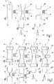
- eine schematische Darstellung der Herstellungsschritte zur Heißformung von Pharmafläschchen gemäß dem Stand der Technik;
- Fig. 2
- eine schematische Darstellung der Herstellungsschritte bei der Formung von Pharmafläschchen gemäß der Erfindung;
- Fig. 3
- einen Vergleich der Natriumabgabe gemäß dem Testverfahren ISO 4802-2 für zwei Borosilikatglastypen (Typ 1 und Typ 2), wobei die Testergebnisse an herkömmlich hergestellten Borosilikatgläsern des Typs 1 mit A1 und des Typs 2 mit B1 bezeichnet sind und den Testergebnissen an den erfindungsgemäß hergestellten Glasfläschchen unter sonst gleichen Bedingungen und Größen gegenübergestellt sind und
- Fig. 4
- eine vergrößerte Darstellung eines Glasröhrchens in der Phase der Durchmesserreduzierung mittels zweier rotierend angetriebener Formkörper.
- Fig. 1
- a schematic representation of the manufacturing steps for hot forming of pharmaceutical vials according to the prior art;
- Fig. 2
- a schematic representation of the manufacturing steps in the formation of pharmaceutical vials according to the invention;
- Fig. 3
- a comparison of the sodium release according to the test method ISO 4802-2 for two borosilicate glass types (type 1 and type 2), the test results on conventionally prepared borosilicate glasses of type 1 with A1 and type 2 with B1 and the test results on the glass vial according to the invention under otherwise identical conditions and sizes are contrasted and
- Fig. 4
- an enlarged view of a glass tube in the phase of diameter reduction by means of two rotationally driven moldings.
Anhand von
Ein Glasrohr 10, das etwa aus einem Borosilikatglas, wie zum Beispiel Fiolax® (eingetragene Marke der SCHOTT AG, Mainz) besteht, wird zwischen zwei Spannfuttern angespannt und um seine Längsachse 12 rotierend angetrieben, wie durch einen Pfeil 13 angedeutet ist.A
Nunmehr wird durch einen seitlich angeordneten Brenner 14, der unmittelbar auf die Manteloberfläche des Glasrohrs 10 gerichtet ist, das Glasrohr 10 in
Untersuchungen der Erfinder haben ergeben, dass insbesondere die Erhitzung durch den Brenner 14, durch die schließlich die Auftrennung des Glasrohrs 16 im Einschnürbereich 16 in zwei geschlossene Teile erfolgt, für ein starkes Abdampfen von Alkaliboraten aus der Glasmatrix verantwortlich ist.Investigations by the inventors have shown that in particular the heating by the
Gemäß dem erfindungsgemäßen Verfahren wird die Alkaliboratabdampfung deutlich reduziert, da die notwendige Temperatur beim Trennen des Glasrohrs deutlich reduziert wird.According to the method of the invention, the alkali borate evaporation is significantly reduced because the necessary temperature is significantly reduced when separating the glass tube.
Dies wird im Folgenden anhand von
Hierbei werden für entsprechende Teile entsprechende Bezugsziffern verwendet.Here, corresponding reference numerals are used for corresponding parts.
Im ersten Schritt gemäß
Auf den Schritt des Auseinanderziehens in Axialrichtung zur Erzeugung eines Einschnürbereiches 16 kann auch verzichtet werden. Stattdessen kann unmittelbar eine Verformung des mindestens bis auf Erweichungstemperatur EW erwärmten Glasrohrs 10 durch Eindrücken des Formteils 28 erfolgen.The step of pulling apart in the axial direction to produce a constricting
Das hierbei verwendete Formteil 28 besteht bevorzugt aus einer Wolframlegierung oder aus Elektrographit und ist an seiner dem Glasrohr 10 zugewandten Oberfläche abgerundet oder zugespitztThe molded
Anschließend wird das Formteil 28 wieder weggeschwenkt und der Brenner 14 vor den verbleibenden Einschnürbereich 16 des Glasrohrs 10" zurückgeschwenkt, um den verbleibenden, schmalen Glasstrang abzuschmelzen.Subsequently, the molded
Es entstehen dann gemäß
Die gegenüber dem Stand der Technik im Wesentlichen dadurch veränderte Verfahrensführung, dass nach einem anfänglichen Erwärmen und ggf. Auseinanderziehen des Glasrohrs der erhitzte Bereich 16 durch radiales Eindrücken eines Formteils 28 stark verjüngt wird, so dass nur noch ein schmaler Reststrang verbleibt, führt dazu, dass bei niedrigerer Temperatur während des Abtrennvorgangs gearbeitet werden kann bzw. dazu, dass der Abtrennvorgang verkürzt wird. Dies hat wiederum zur Folge, dass deutlich weniger Alkaliverluste auftreten und schließlich auch die Testergebnisse beim Auslaugtest gemäß ISO 4802 deutlich verbessert sind. Wird auf den Schritt des Auseinanderziehens sogar verzichtet, so reicht die Erweichungstemperatur oder eine geringfügig darüber liegende Temperatur aus, um die notwendige Durchmesserverringerung zu erzielen.The methodology, which is essentially modified by comparison with the prior art, that after an initial heating and possibly pulling apart of the glass tube, the
Es versteht sich natürlich, dass zunächst ein etwaiger Halsbereich mittels einer Brennerflamme und ggf. einem Formteil am unteren Ende eines Glasrohrs geformt werden kann, wie im Stand der Technik grundsätzlich bekannt, bevor mit der Durchmesserverringerung und dem nachfolgenden Trennvorgang begonnen wird. Da dies nicht zum Kern der Erfindung gehört, wurde dies hier nicht näher beschrieben.It goes without saying that, first of all, any neck area can be formed by means of a burner flame and possibly a molded part at the lower end of a glass tube, as is basically known in the prior art, before the diameter reduction and the subsequent separation process are started. Since this is not part of the core of the invention, this has not been described in detail here.
Zum Vergleich wurden an einer Einstationen-Rohrbearbeitungsanlage mit Glasrohren des Glastyps 1 bzw. 2 (beides Borosilikatgläser der Schott AG, Mainz) mit einem Außendurchmesser von 16 mm bei einer Wandstärke von 1 mm Behälter nach der herkömmlichen Formgebungsmethode gemäß
Der Glastyp 2 ist das von der Schott AG unter der Marke Fiolax® vertriebene Borosilikatglas, das die folgende Hauptbestandteile (im Gew.-% auf Oxidbasis) aufweist:
Die Erweichungstemperatur EW liegt bei nur 785 °C, während die Verarbeitungstemperatur VA bei 1165 °C liegt. Bei der herkömmlichen Verarbeitung musste das Glasrohr zwecks Auseinanderziehen zur Erzeugung einer Einschnürung bis auf die Verarbeitungstemperatur erwärmt werden.The softening temperature E W is only 785 ° C, while the processing temperature V A is 1165 ° C. In conventional processing, the glass tube had to be heated to the processing temperature to be pulled apart to create a constriction.
Die Gesamtverarbeitungszeit vom Beginn des Aufheizens des Glasrohres bis zur Ausbildung der Glasböden an beiden Rohrenden war bei beiden Herstellverfahren identisch.The total processing time from the beginning of the heating of the glass tube to the formation of the glass bottoms at both ends of the tube was identical in both production methods.
Beide Behälter, die nach den herkömmlichen Verfahren und nach dem erfindungsgemäßen Verfahren hergestellt waren, wurden auf ihre Natriumfreisetzung an der Behälterinnenoberfläche gemäß dem Testverfahren ISO 4802-2 analysiert.Both containers, which were prepared by the conventional methods and by the method according to the invention, were analyzed for their sodium release on the container inner surface according to the test method ISO 4802-2.
Das Testverfahren ergibt sich aus der Norm ISO 4802-2 und ist in "
Die sich ergebende Natriumfreisetzung in µm/cm2 ist in
A2 und B2 zeigen die entsprechende Natriumfreisetzung an den nach dem erfindungsgemäßen Verfahren hergestellten Glasproben.A2 and B2 show the corresponding sodium release on the glass samples prepared by the process according to the invention.
Es zeigt sich eine deutliche Verminderung der Natriumfreisetzung bei den nach dem erfindungsgemäßen Verfahren hergestellten Glasfläschchen.It shows a significant reduction of the sodium release in the glass bottles produced by the process according to the invention.
In
Hierbei werden entsprechende Teile mit entsprechenden Bezugsziffern bezeichnet.Here, corresponding parts are designated by corresponding reference numerals.
In diesem Fall wird der Einschnürbereich 16 des rotierenden Glasrohrs 10' nicht nur mit einem einzigen Formkörper, wie zuvor beschrieben, sondern von beiden Seiten her mit je einem Formkörper 28a beaufschlagt.In this case, the constricting
Zusätzlich sind die Formkörper 28a noch rotierend angetrieben. Sie können, wie beispielhaft dargestellt ist, an einem beweglichen Rahmen 34 mittels einer Welle 36 gelagert sein und über einen Antrieb 32 angetrieben werden, der zusätzlich noch mit einer Heizeinrichtung gekoppelt sein kann, um die Formkörper 28a zusätzlich zu beheizen.In addition, the molded
Vorzugsweise bestehen die Formkörper 28 bzw. 28a aus einer Wolframlegierung, reinem Wolfram oder Elektrographit. Dies ergibt ein besonders günstiges Benetzungsverhalten gegenüber der Glasoberfläche. Grundsätzlich ist auch eine Herstellung aus warmfestem Stahl denkbar, jedoch ist das Benetzungsverhalten bei Wolfram bzw. Graphit günstiger. Vorzugsweise verjüngt sich der Formkörper 28 bzw. 28a in Richtung zum Glasrohr hin, insbesondere kann eine spitz zulaufende Form verwendet werden. Im Falle von rotierend angetriebenen Formkörpern 28a gemäß
Es ist davon auszugehen, dass mit einer derartigen Ausführung gemäß
Claims (12)
- A method of producing glass vials from a glass tube (10), in particular pharmaceutical vials and pharmaceutical ampoules, comprising the following steps:(a) rotating the glass tube (10) about its longitudinal axis (12);(b) local heating of the glass tube (10) by means of a burner (14) from at least one side at least up to the softening temperature (Ew) of the glass;(c) reducing the diameter by pressing at least one forming body (28) laterally against the heated region (16) and(d) separating the glass tube (10) by means of the burner (14) in the heated area (16) in which the diameter has been reduced, thereby obtaining an upper and a lower tube section each having a closed bottom.
- The method of claim 1, wherein after the step (b) an additional step (b1) is performed, wherein an extending of the rotating glass tube (10) in axial direction is performed for generating a constriction region (16).
- The method of claim 1, wherein the steps (a) to (d) and possibly (b1) are performed in the given sequence while the glass tube (10) is rotating.
- The method of any of claims 1, 2 or 3, wherein the remaining closed upper tube section (10"') after the separating step (d) is pierced at its closed end (21) by means of a burner (20).
- The method of any of the preceding claims, wherein the rotating glass tube (10) after the step (a) is initially heated at one end and formed for generating a neck region (23) of the vial (18) to be formed, and subsequently is heated in a predetermined distance from the end according to the step (b).
- The method of any of the preceding claims, wherein the glass tube (10) is driven at a rotating speed of 200 min-1 to 500 min-1, preferably 250 min-1 to 450 min-1 and more preferably 300 min-1 to 400 min-1.
- The method of any of the preceding claims, wherein the forming body (28, 28a) consists of a tungsten alloy, of electro-graphite or of a heat-resistant steel.
- The method of any of the preceding claims, wherein the forming body (28, 28a) is driven rotatingly.
- The method of any of the preceding claims, wherein the forming body (28, 28a) is heated.
- The method of any of the preceding claims, wherein the forming body (28, 28a) tapers towards the glass tube (10), preferably is configured running pointed.
- The method of any of the preceding claims, wherein the forming body (28) is advanced on both sides.
- The method of any of the preceding claims, wherein a glass tube (10) of a neutral glass configured as a borosilicate glass is utilized for preparing the glass vial (18).
Priority Applications (1)
| Application Number | Priority Date | Filing Date | Title |
|---|---|---|---|
| EP19212455.0A EP3632859A1 (en) | 2013-07-17 | 2014-06-16 | Method for producing glass vials |
Applications Claiming Priority (2)
| Application Number | Priority Date | Filing Date | Title |
|---|---|---|---|
| DE102013107607.6A DE102013107607B4 (en) | 2013-07-17 | 2013-07-17 | Method of making glass vials |
| PCT/EP2014/062550 WO2015007445A1 (en) | 2013-07-17 | 2014-06-16 | Method for producing glass vials |
Related Child Applications (1)
| Application Number | Title | Priority Date | Filing Date |
|---|---|---|---|
| EP19212455.0A Division EP3632859A1 (en) | 2013-07-17 | 2014-06-16 | Method for producing glass vials |
Publications (2)
| Publication Number | Publication Date |
|---|---|
| EP3022160A1 EP3022160A1 (en) | 2016-05-25 |
| EP3022160B1 true EP3022160B1 (en) | 2019-12-04 |
Family
ID=51022831
Family Applications (2)
| Application Number | Title | Priority Date | Filing Date |
|---|---|---|---|
| EP19212455.0A Withdrawn EP3632859A1 (en) | 2013-07-17 | 2014-06-16 | Method for producing glass vials |
| EP14733575.6A Active EP3022160B1 (en) | 2013-07-17 | 2014-06-16 | Method for producing glass vials |
Family Applications Before (1)
| Application Number | Title | Priority Date | Filing Date |
|---|---|---|---|
| EP19212455.0A Withdrawn EP3632859A1 (en) | 2013-07-17 | 2014-06-16 | Method for producing glass vials |
Country Status (6)
| Country | Link |
|---|---|
| US (2) | US10442718B2 (en) |
| EP (2) | EP3632859A1 (en) |
| JP (2) | JP6567516B2 (en) |
| CN (1) | CN105377779B (en) |
| DE (1) | DE102013107607B4 (en) |
| WO (1) | WO2015007445A1 (en) |
Families Citing this family (22)
| Publication number | Priority date | Publication date | Assignee | Title |
|---|---|---|---|---|
| ES2777221T3 (en) * | 2013-05-30 | 2020-08-04 | Dalwick Continental Corp | Method for manufacturing glass containers for pharmaceutical use |
| JP6690640B2 (en) * | 2015-04-24 | 2020-04-28 | ニプロ株式会社 | Method for manufacturing medical glass container and fire blasting device having rotating device |
| US10512281B2 (en) * | 2016-01-21 | 2019-12-24 | R.Y.L. Inc. | Method of making a disposable vial for packing tobacco to be smoked |
| JP6801289B2 (en) * | 2016-08-16 | 2020-12-16 | 日本電気硝子株式会社 | Manufacturing method of glass tube |
| DE102016122061A1 (en) * | 2016-11-16 | 2018-05-17 | Schott Ag | Process for the preparation of glass vials with low delamination tendency under the influence of a purging gas flow |
| US20180164226A1 (en) * | 2016-12-08 | 2018-06-14 | Schott Ag | Method for further processing a glass tube semi-finished product |
| DE102016124833A1 (en) | 2016-12-19 | 2018-06-21 | Schott Ag | Method for producing a hollow glass product from a glass tube semifinished product with markings, as well as uses thereof |
| DE102016125129A1 (en) | 2016-12-21 | 2018-06-21 | Schott Ag | A method for producing a glass tube semi-finished product or a hollow glass product produced therefrom with markings, as well as uses thereof |
| WO2018132637A1 (en) * | 2017-01-13 | 2018-07-19 | Momentive Performance Materials Inc. | Fused quartz container having low levels of surface defects |
| US10968133B2 (en) | 2017-11-30 | 2021-04-06 | Corning Incorporated | Methods for minimizing SHR in glass articles by producing a gas flow during pharmaceutical part converting |
| US11279647B2 (en) | 2017-11-30 | 2022-03-22 | Corning Incorporated | Glass articles made from laminated glass tubing and systems and methods for converting laminated glass tubing into the glass articles |
| US11186513B2 (en) * | 2017-11-30 | 2021-11-30 | Corning Incorporated | Systems and methods for minimizing SHR from pharmaceutical part converting using negative pressure evacuation |
| US11339079B2 (en) | 2017-11-30 | 2022-05-24 | Corning Incorporated | Systems and methods for minimizing SHR from pharmaceutical part converting using pulsed ejection |
| US11420893B2 (en) | 2017-11-30 | 2022-08-23 | Corning Incorporated | Systems and methods for minimizing SHR from piercing during pharmaceutical part converting using a gas flow |
| DE102018104163A1 (en) * | 2018-02-23 | 2019-08-29 | Schott Ag | Glass vial with low migration load |
| EP3647287B1 (en) * | 2018-10-30 | 2024-04-17 | SCHOTT Pharma AG & Co. KGaA | Container precursor having a wall of glass which is superimposed by a plurality of particles |
| DE102018127528A1 (en) * | 2018-11-05 | 2020-05-07 | Schott Ag | Glass containers and method of making same |
| EP3757076B1 (en) * | 2019-06-26 | 2022-08-24 | Schott Ag | Method for controlling alkali emissions of a glass element during hot forming |
| EP3842390B1 (en) * | 2019-12-20 | 2024-04-24 | SCHOTT Pharma AG & Co. KGaA | Bottom forming process |
| CN111018324B (en) * | 2020-03-04 | 2020-07-24 | 江苏琳琅玻璃制品有限公司 | Cutting device for glass tube |
| DE102020114886A1 (en) * | 2020-06-04 | 2021-12-09 | Gerresheimer Bünde Gmbh | Method and a system for producing a glass article |
| CN112919784A (en) * | 2021-02-22 | 2021-06-08 | 上海清水日用制品有限公司 | Method for manufacturing single-layer glass cup |
Citations (2)
| Publication number | Priority date | Publication date | Assignee | Title |
|---|---|---|---|---|
| US4869744A (en) * | 1987-06-15 | 1989-09-26 | U.S. Philips Corporation | Method of manufacturing an electric lamp, and device for performing such a method |
| JP2010274091A (en) * | 2009-04-30 | 2010-12-09 | Nipro Corp | Method for manufacturing medical glass container |
Family Cites Families (27)
| Publication number | Priority date | Publication date | Assignee | Title |
|---|---|---|---|---|
| US307797A (en) * | 1884-11-11 | Joseph p | ||
| US2087947A (en) * | 1932-11-22 | 1937-07-27 | Dichter Jakob | Manufacture of glass vessels from tubing |
| US2447568A (en) * | 1944-01-20 | 1948-08-24 | Eisler Charles | Machine for forming bottoms on glass tubes |
| US2835079A (en) * | 1953-06-30 | 1958-05-20 | Westinghouse Electric Corp | Tubular lamp bulb machine |
| US2935819A (en) * | 1955-06-07 | 1960-05-10 | Dichter Jakob | Machine for the manufacture of small glass bottles or the like from glass tubes |
| BE646104A (en) | 1963-04-05 | |||
| GB1084252A (en) | 1964-02-12 | |||
| US3537833A (en) | 1968-03-18 | 1970-11-03 | Corning Glass Works | Method for producing hollow glass spheres |
| JPS5443005B1 (en) * | 1968-12-11 | 1979-12-18 | ||
| DE2818486A1 (en) * | 1978-04-27 | 1979-10-31 | Philips Patentverwaltung | Glass lamp bulbs with pumping tubes - are formed using sequence of heating and drawing operations converting single tube into two lamp bulbs |
| SU1172892A1 (en) * | 1983-05-26 | 1985-08-15 | Специальное Проектно-Конструкторское Бюро Медицинской Промышленности Ленинградского Научно-Производственного Объединения "Прогресс" | Process for manufacturing glass articles |
| NL8402225A (en) | 1984-07-13 | 1986-02-03 | Philips Nv | METHOD FOR MANUFACTURING SOLID GLASS PREFORMS FROM HOLLOW FORMS |
| GB8500511D0 (en) | 1985-01-09 | 1985-02-13 | Emi Plc Thorn | Tungsten halogen incandescent lamp |
| JP2980957B2 (en) * | 1990-05-15 | 1999-11-22 | 旭テクノグラス株式会社 | Method and apparatus for producing glass body for lamp |
| US5221311A (en) * | 1992-01-10 | 1993-06-22 | Rising Peter E | Evacuated sampling vial |
| DE4444547C2 (en) | 1994-12-14 | 1997-02-27 | Schott Rohrglas Gmbh | Process for the heat-soft cutting of thin-walled glass tubes or plates |
| EP1043732B1 (en) * | 1997-12-26 | 2006-10-11 | Kureha Corporation | Polymer electrolyte and nonaqueous battery containing the same |
| JP2001328612A (en) * | 2000-05-22 | 2001-11-27 | Daiwa Tokushu Glass Kk | Low alkaline glass container and its manufacturing method |
| EP1349439B1 (en) * | 2002-03-28 | 2005-11-09 | Plasma Treat GmbH | Method and device for glass ampule sealing |
| DE10332176B4 (en) * | 2002-07-24 | 2007-04-05 | Schott Ag | Method for reducing the contamination with alkali compounds of the inner surface of hollow bodies made of glass tube and container, and its use for medical purposes |
| WO2006123621A1 (en) * | 2005-05-16 | 2006-11-23 | Nipro Corporation | Vials and processes for producing the same |
| DE102008051614B4 (en) | 2008-10-09 | 2012-09-20 | Schott Ag | Process for the production of glass packaging materials for pharmaceutical products |
| DE102009008689B4 (en) * | 2009-02-06 | 2011-03-10 | Schott Ag | Method for producing a container made of glass from the melt and container made of glass |
| CN101857356B (en) * | 2009-04-07 | 2014-03-26 | 尼普洛株式会社 | Method for producing medical glass container and burner for inner surface treatment of medical glass container |
| DE102009018203A1 (en) * | 2009-04-22 | 2010-11-11 | Schott Ag | Concentrator optics: Low-cost production of rotationally symmetric and longitudinal optical elements |
| CN101874760B (en) * | 2009-04-30 | 2014-10-29 | 尼普洛株式会社 | method for producing a medical glass container |
| CN102503089A (en) * | 2011-10-09 | 2012-06-20 | 双峰格雷斯海姆医药包装(镇江)有限公司 | Manufacturing process of ampoule bottle |
-
2013
- 2013-07-17 DE DE102013107607.6A patent/DE102013107607B4/en not_active Revoked
-
2014
- 2014-06-16 WO PCT/EP2014/062550 patent/WO2015007445A1/en active Application Filing
- 2014-06-16 JP JP2016526478A patent/JP6567516B2/en active Active
- 2014-06-16 EP EP19212455.0A patent/EP3632859A1/en not_active Withdrawn
- 2014-06-16 EP EP14733575.6A patent/EP3022160B1/en active Active
- 2014-06-16 CN CN201480040577.3A patent/CN105377779B/en active Active
-
2016
- 2016-01-19 US US15/000,072 patent/US10442718B2/en active Active
-
2019
- 2019-07-31 JP JP2019141216A patent/JP2019214508A/en active Pending
- 2019-09-09 US US16/564,089 patent/US20200002212A1/en not_active Abandoned
Patent Citations (2)
| Publication number | Priority date | Publication date | Assignee | Title |
|---|---|---|---|---|
| US4869744A (en) * | 1987-06-15 | 1989-09-26 | U.S. Philips Corporation | Method of manufacturing an electric lamp, and device for performing such a method |
| JP2010274091A (en) * | 2009-04-30 | 2010-12-09 | Nipro Corp | Method for manufacturing medical glass container |
Non-Patent Citations (1)
| Title |
|---|
| NIPRO CORPORATION: "IN304080 - Method for producing medical glass container", 4 May 2012 (2012-05-04), XP055555724, Retrieved from the Internet <URL:http://ipindiaservices.gov.in/PublicSearch/> [retrieved on 20190212] * |
Also Published As
| Publication number | Publication date |
|---|---|
| WO2015007445A1 (en) | 2015-01-22 |
| US20200002212A1 (en) | 2020-01-02 |
| US20160130170A1 (en) | 2016-05-12 |
| JP2019214508A (en) | 2019-12-19 |
| CN105377779B (en) | 2018-05-08 |
| DE102013107607A1 (en) | 2015-01-22 |
| JP2016528144A (en) | 2016-09-15 |
| JP6567516B2 (en) | 2019-08-28 |
| EP3632859A1 (en) | 2020-04-08 |
| CN105377779A (en) | 2016-03-02 |
| EP3022160A1 (en) | 2016-05-25 |
| US10442718B2 (en) | 2019-10-15 |
| DE102013107607B4 (en) | 2017-09-21 |
Similar Documents
| Publication | Publication Date | Title |
|---|---|---|
| EP3022160B1 (en) | Method for producing glass vials | |
| EP2977358B1 (en) | Method for thermally treating an annular area of an internal surface of a glass container produced from a borosilicate glass | |
| EP2223715B1 (en) | Production of a pharmaceutical container from a molten mass | |
| DE2515558C3 (en) | Process for manufacturing optical lenses | |
| DE10332176B4 (en) | Method for reducing the contamination with alkali compounds of the inner surface of hollow bodies made of glass tube and container, and its use for medical purposes | |
| DE102005038764B3 (en) | Method for making syringes uses glassworking machine with turntable fed with glass tubes, on which points of syringes are formed, tubes then being transferred to second turntable where they are inverted and flange for finger is formed | |
| EP3156377B1 (en) | Wolfram-containing forming mandrel for glass forming | |
| DE10224833B4 (en) | Pipe semi-finished product and method for producing glass containers from a semi-finished tube | |
| WO2005121037A1 (en) | Method for the production of an optical component made from quartz glass | |
| EP2816017B1 (en) | Method and apparatus for creating a predetermined fracture point on a breakable ampoule and associated product | |
| EP2216302B1 (en) | Production of a glass container from a molten mass | |
| DE2705527B2 (en) | Method for separating glass gobs | |
| EP3121154B1 (en) | Glass-forming mandrel with a diffusion layer | |
| DE102011013623B4 (en) | Process for the preparation of a glass tube suitable for the manufacture of ampoules and vials and apparatus for the production thereof | |
| DE1427915A1 (en) | Method and device for manufacturing seamless tubes | |
| EP3919452B1 (en) | Method and system for manufacturing a glass container | |
| DE102014100942B4 (en) | Method for producing a stemmed glass | |
| DE3507498A1 (en) | METHOD AND DEVICE FOR PRODUCING HOLLOW GLASSES WITH A SMOOTH, ROUNDED EDGE | |
| DE102010034474B4 (en) | Method for producing a glass container from the melt | |
| DE10019875B4 (en) | Device for producing multi-layer glass tubes, in particular colored glass tubes | |
| WO1991001281A1 (en) | Process and device for moulding glass | |
| DE977540C (en) | Method and device for manufacturing medicine jars and bottles from glass tubes | |
| DE601015C (en) | Process for the production of double-walled glass containers | |
| DE674546C (en) | Process for the production of mesh glasses or diatrets | |
| DE665944C (en) | Method and device for manufacturing glass tubes with a precise interior shape |
Legal Events
| Date | Code | Title | Description |
|---|---|---|---|
| PUAI | Public reference made under article 153(3) epc to a published international application that has entered the european phase |
Free format text: ORIGINAL CODE: 0009012 |
|
| 17P | Request for examination filed |
Effective date: 20160211 |
|
| AK | Designated contracting states |
Kind code of ref document: A1 Designated state(s): AL AT BE BG CH CY CZ DE DK EE ES FI FR GB GR HR HU IE IS IT LI LT LU LV MC MK MT NL NO PL PT RO RS SE SI SK SM TR |
|
| AX | Request for extension of the european patent |
Extension state: BA ME |
|
| DAX | Request for extension of the european patent (deleted) | ||
| TPAC | Observations filed by third parties |
Free format text: ORIGINAL CODE: EPIDOSNTIPA |
|
| STAA | Information on the status of an ep patent application or granted ep patent |
Free format text: STATUS: EXAMINATION IS IN PROGRESS |
|
| 17Q | First examination report despatched |
Effective date: 20190222 |
|
| GRAP | Despatch of communication of intention to grant a patent |
Free format text: ORIGINAL CODE: EPIDOSNIGR1 |
|
| STAA | Information on the status of an ep patent application or granted ep patent |
Free format text: STATUS: GRANT OF PATENT IS INTENDED |
|
| RIC1 | Information provided on ipc code assigned before grant |
Ipc: C03B 21/06 20060101ALI20190823BHEP Ipc: C03B 23/049 20060101AFI20190823BHEP Ipc: A61J 1/06 20060101ALI20190823BHEP Ipc: B65D 1/09 20060101ALI20190823BHEP Ipc: C03B 23/09 20060101ALI20190823BHEP Ipc: C03B 23/11 20060101ALI20190823BHEP |
|
| INTG | Intention to grant announced |
Effective date: 20190913 |
|
| GRAS | Grant fee paid |
Free format text: ORIGINAL CODE: EPIDOSNIGR3 |
|
| GRAA | (expected) grant |
Free format text: ORIGINAL CODE: 0009210 |
|
| STAA | Information on the status of an ep patent application or granted ep patent |
Free format text: STATUS: THE PATENT HAS BEEN GRANTED |
|
| AK | Designated contracting states |
Kind code of ref document: B1 Designated state(s): AL AT BE BG CH CY CZ DE DK EE ES FI FR GB GR HR HU IE IS IT LI LT LU LV MC MK MT NL NO PL PT RO RS SE SI SK SM TR |
|
| REG | Reference to a national code |
Ref country code: GB Ref legal event code: FG4D Free format text: NOT ENGLISH |
|
| REG | Reference to a national code |
Ref country code: CH Ref legal event code: EP |
|
| REG | Reference to a national code |
Ref country code: AT Ref legal event code: REF Ref document number: 1209188 Country of ref document: AT Kind code of ref document: T Effective date: 20191215 |
|
| REG | Reference to a national code |
Ref country code: DE Ref legal event code: R096 Ref document number: 502014013179 Country of ref document: DE |
|
| REG | Reference to a national code |
Ref country code: IE Ref legal event code: FG4D Free format text: LANGUAGE OF EP DOCUMENT: GERMAN |
|
| REG | Reference to a national code |
Ref country code: NL Ref legal event code: MP Effective date: 20191204 |
|
| REG | Reference to a national code |
Ref country code: LT Ref legal event code: MG4D |
|
| PG25 | Lapsed in a contracting state [announced via postgrant information from national office to epo] |
Ref country code: LV Free format text: LAPSE BECAUSE OF FAILURE TO SUBMIT A TRANSLATION OF THE DESCRIPTION OR TO PAY THE FEE WITHIN THE PRESCRIBED TIME-LIMIT Effective date: 20191204 Ref country code: SE Free format text: LAPSE BECAUSE OF FAILURE TO SUBMIT A TRANSLATION OF THE DESCRIPTION OR TO PAY THE FEE WITHIN THE PRESCRIBED TIME-LIMIT Effective date: 20191204 Ref country code: NO Free format text: LAPSE BECAUSE OF FAILURE TO SUBMIT A TRANSLATION OF THE DESCRIPTION OR TO PAY THE FEE WITHIN THE PRESCRIBED TIME-LIMIT Effective date: 20200304 Ref country code: BG Free format text: LAPSE BECAUSE OF FAILURE TO SUBMIT A TRANSLATION OF THE DESCRIPTION OR TO PAY THE FEE WITHIN THE PRESCRIBED TIME-LIMIT Effective date: 20200304 Ref country code: FI Free format text: LAPSE BECAUSE OF FAILURE TO SUBMIT A TRANSLATION OF THE DESCRIPTION OR TO PAY THE FEE WITHIN THE PRESCRIBED TIME-LIMIT Effective date: 20191204 Ref country code: LT Free format text: LAPSE BECAUSE OF FAILURE TO SUBMIT A TRANSLATION OF THE DESCRIPTION OR TO PAY THE FEE WITHIN THE PRESCRIBED TIME-LIMIT Effective date: 20191204 Ref country code: GR Free format text: LAPSE BECAUSE OF FAILURE TO SUBMIT A TRANSLATION OF THE DESCRIPTION OR TO PAY THE FEE WITHIN THE PRESCRIBED TIME-LIMIT Effective date: 20200305 |
|
| PG25 | Lapsed in a contracting state [announced via postgrant information from national office to epo] |
Ref country code: HR Free format text: LAPSE BECAUSE OF FAILURE TO SUBMIT A TRANSLATION OF THE DESCRIPTION OR TO PAY THE FEE WITHIN THE PRESCRIBED TIME-LIMIT Effective date: 20191204 Ref country code: RS Free format text: LAPSE BECAUSE OF FAILURE TO SUBMIT A TRANSLATION OF THE DESCRIPTION OR TO PAY THE FEE WITHIN THE PRESCRIBED TIME-LIMIT Effective date: 20191204 |
|
| PG25 | Lapsed in a contracting state [announced via postgrant information from national office to epo] |
Ref country code: AL Free format text: LAPSE BECAUSE OF FAILURE TO SUBMIT A TRANSLATION OF THE DESCRIPTION OR TO PAY THE FEE WITHIN THE PRESCRIBED TIME-LIMIT Effective date: 20191204 |
|
| PG25 | Lapsed in a contracting state [announced via postgrant information from national office to epo] |
Ref country code: CZ Free format text: LAPSE BECAUSE OF FAILURE TO SUBMIT A TRANSLATION OF THE DESCRIPTION OR TO PAY THE FEE WITHIN THE PRESCRIBED TIME-LIMIT Effective date: 20191204 Ref country code: NL Free format text: LAPSE BECAUSE OF FAILURE TO SUBMIT A TRANSLATION OF THE DESCRIPTION OR TO PAY THE FEE WITHIN THE PRESCRIBED TIME-LIMIT Effective date: 20191204 Ref country code: RO Free format text: LAPSE BECAUSE OF FAILURE TO SUBMIT A TRANSLATION OF THE DESCRIPTION OR TO PAY THE FEE WITHIN THE PRESCRIBED TIME-LIMIT Effective date: 20191204 Ref country code: EE Free format text: LAPSE BECAUSE OF FAILURE TO SUBMIT A TRANSLATION OF THE DESCRIPTION OR TO PAY THE FEE WITHIN THE PRESCRIBED TIME-LIMIT Effective date: 20191204 Ref country code: ES Free format text: LAPSE BECAUSE OF FAILURE TO SUBMIT A TRANSLATION OF THE DESCRIPTION OR TO PAY THE FEE WITHIN THE PRESCRIBED TIME-LIMIT Effective date: 20191204 Ref country code: PT Free format text: LAPSE BECAUSE OF FAILURE TO SUBMIT A TRANSLATION OF THE DESCRIPTION OR TO PAY THE FEE WITHIN THE PRESCRIBED TIME-LIMIT Effective date: 20200429 |
|
| PG25 | Lapsed in a contracting state [announced via postgrant information from national office to epo] |
Ref country code: SM Free format text: LAPSE BECAUSE OF FAILURE TO SUBMIT A TRANSLATION OF THE DESCRIPTION OR TO PAY THE FEE WITHIN THE PRESCRIBED TIME-LIMIT Effective date: 20191204 Ref country code: SK Free format text: LAPSE BECAUSE OF FAILURE TO SUBMIT A TRANSLATION OF THE DESCRIPTION OR TO PAY THE FEE WITHIN THE PRESCRIBED TIME-LIMIT Effective date: 20191204 Ref country code: IS Free format text: LAPSE BECAUSE OF FAILURE TO SUBMIT A TRANSLATION OF THE DESCRIPTION OR TO PAY THE FEE WITHIN THE PRESCRIBED TIME-LIMIT Effective date: 20200404 |
|
| REG | Reference to a national code |
Ref country code: DE Ref legal event code: R097 Ref document number: 502014013179 Country of ref document: DE |
|
| PLBE | No opposition filed within time limit |
Free format text: ORIGINAL CODE: 0009261 |
|
| STAA | Information on the status of an ep patent application or granted ep patent |
Free format text: STATUS: NO OPPOSITION FILED WITHIN TIME LIMIT |
|
| PG25 | Lapsed in a contracting state [announced via postgrant information from national office to epo] |
Ref country code: DK Free format text: LAPSE BECAUSE OF FAILURE TO SUBMIT A TRANSLATION OF THE DESCRIPTION OR TO PAY THE FEE WITHIN THE PRESCRIBED TIME-LIMIT Effective date: 20191204 |
|
| 26N | No opposition filed |
Effective date: 20200907 |
|
| PG25 | Lapsed in a contracting state [announced via postgrant information from national office to epo] |
Ref country code: SI Free format text: LAPSE BECAUSE OF FAILURE TO SUBMIT A TRANSLATION OF THE DESCRIPTION OR TO PAY THE FEE WITHIN THE PRESCRIBED TIME-LIMIT Effective date: 20191204 Ref country code: PL Free format text: LAPSE BECAUSE OF FAILURE TO SUBMIT A TRANSLATION OF THE DESCRIPTION OR TO PAY THE FEE WITHIN THE PRESCRIBED TIME-LIMIT Effective date: 20191204 |
|
| PG25 | Lapsed in a contracting state [announced via postgrant information from national office to epo] |
Ref country code: MC Free format text: LAPSE BECAUSE OF FAILURE TO SUBMIT A TRANSLATION OF THE DESCRIPTION OR TO PAY THE FEE WITHIN THE PRESCRIBED TIME-LIMIT Effective date: 20191204 |
|
| GBPC | Gb: european patent ceased through non-payment of renewal fee |
Effective date: 20200616 |
|
| PG25 | Lapsed in a contracting state [announced via postgrant information from national office to epo] |
Ref country code: LU Free format text: LAPSE BECAUSE OF NON-PAYMENT OF DUE FEES Effective date: 20200616 |
|
| PG25 | Lapsed in a contracting state [announced via postgrant information from national office to epo] |
Ref country code: GB Free format text: LAPSE BECAUSE OF NON-PAYMENT OF DUE FEES Effective date: 20200616 Ref country code: IE Free format text: LAPSE BECAUSE OF NON-PAYMENT OF DUE FEES Effective date: 20200616 |
|
| REG | Reference to a national code |
Ref country code: AT Ref legal event code: MM01 Ref document number: 1209188 Country of ref document: AT Kind code of ref document: T Effective date: 20200616 |
|
| PG25 | Lapsed in a contracting state [announced via postgrant information from national office to epo] |
Ref country code: AT Free format text: LAPSE BECAUSE OF NON-PAYMENT OF DUE FEES Effective date: 20200616 |
|
| PG25 | Lapsed in a contracting state [announced via postgrant information from national office to epo] |
Ref country code: TR Free format text: LAPSE BECAUSE OF FAILURE TO SUBMIT A TRANSLATION OF THE DESCRIPTION OR TO PAY THE FEE WITHIN THE PRESCRIBED TIME-LIMIT Effective date: 20191204 Ref country code: MT Free format text: LAPSE BECAUSE OF FAILURE TO SUBMIT A TRANSLATION OF THE DESCRIPTION OR TO PAY THE FEE WITHIN THE PRESCRIBED TIME-LIMIT Effective date: 20191204 Ref country code: CY Free format text: LAPSE BECAUSE OF FAILURE TO SUBMIT A TRANSLATION OF THE DESCRIPTION OR TO PAY THE FEE WITHIN THE PRESCRIBED TIME-LIMIT Effective date: 20191204 |
|
| PG25 | Lapsed in a contracting state [announced via postgrant information from national office to epo] |
Ref country code: MK Free format text: LAPSE BECAUSE OF FAILURE TO SUBMIT A TRANSLATION OF THE DESCRIPTION OR TO PAY THE FEE WITHIN THE PRESCRIBED TIME-LIMIT Effective date: 20191204 |
|
| REG | Reference to a national code |
Ref country code: DE Ref legal event code: R081 Ref document number: 502014013179 Country of ref document: DE Owner name: SCHOTT PHARMA AG & CO. KGAA, DE Free format text: FORMER OWNER: SCHOTT AG, 55122 MAINZ, DE |
|
| REG | Reference to a national code |
Ref country code: BE Ref legal event code: PD Owner name: SCHOTT PHARMA AG & CO. KGAA; DE Free format text: DETAILS ASSIGNMENT: CHANGE OF OWNER(S), ASSIGNMENT; FORMER OWNER NAME: SCHOTT AG Effective date: 20221130 |
|
| P01 | Opt-out of the competence of the unified patent court (upc) registered |
Effective date: 20230516 |
|
| PGFP | Annual fee paid to national office [announced via postgrant information from national office to epo] |
Ref country code: FR Payment date: 20230628 Year of fee payment: 10 Ref country code: DE Payment date: 20230620 Year of fee payment: 10 |
|
| PGFP | Annual fee paid to national office [announced via postgrant information from national office to epo] |
Ref country code: BE Payment date: 20230620 Year of fee payment: 10 |
|
| PGFP | Annual fee paid to national office [announced via postgrant information from national office to epo] |
Ref country code: IT Payment date: 20230623 Year of fee payment: 10 Ref country code: CH Payment date: 20230702 Year of fee payment: 10 |