EP3022040B2 - Device for producing films stretched in-line - Google Patents
Device for producing films stretched in-line Download PDFInfo
- Publication number
- EP3022040B2 EP3022040B2 EP14728836.9A EP14728836A EP3022040B2 EP 3022040 B2 EP3022040 B2 EP 3022040B2 EP 14728836 A EP14728836 A EP 14728836A EP 3022040 B2 EP3022040 B2 EP 3022040B2
- Authority
- EP
- European Patent Office
- Prior art keywords
- stretching
- rollers
- film
- unit
- temperature
- Prior art date
- Legal status (The legal status is an assumption and is not a legal conclusion. Google has not performed a legal analysis and makes no representation as to the accuracy of the status listed.)
- Active
Links
Images
Classifications
-
- B—PERFORMING OPERATIONS; TRANSPORTING
- B29—WORKING OF PLASTICS; WORKING OF SUBSTANCES IN A PLASTIC STATE IN GENERAL
- B29C—SHAPING OR JOINING OF PLASTICS; SHAPING OF MATERIAL IN A PLASTIC STATE, NOT OTHERWISE PROVIDED FOR; AFTER-TREATMENT OF THE SHAPED PRODUCTS, e.g. REPAIRING
- B29C48/00—Extrusion moulding, i.e. expressing the moulding material through a die or nozzle which imparts the desired form; Apparatus therefor
- B29C48/001—Combinations of extrusion moulding with other shaping operations
- B29C48/0018—Combinations of extrusion moulding with other shaping operations combined with shaping by orienting, stretching or shrinking, e.g. film blowing
-
- B—PERFORMING OPERATIONS; TRANSPORTING
- B29—WORKING OF PLASTICS; WORKING OF SUBSTANCES IN A PLASTIC STATE IN GENERAL
- B29C—SHAPING OR JOINING OF PLASTICS; SHAPING OF MATERIAL IN A PLASTIC STATE, NOT OTHERWISE PROVIDED FOR; AFTER-TREATMENT OF THE SHAPED PRODUCTS, e.g. REPAIRING
- B29C48/00—Extrusion moulding, i.e. expressing the moulding material through a die or nozzle which imparts the desired form; Apparatus therefor
- B29C48/03—Extrusion moulding, i.e. expressing the moulding material through a die or nozzle which imparts the desired form; Apparatus therefor characterised by the shape of the extruded material at extrusion
- B29C48/09—Articles with cross-sections having partially or fully enclosed cavities, e.g. pipes or channels
- B29C48/10—Articles with cross-sections having partially or fully enclosed cavities, e.g. pipes or channels flexible, e.g. blown foils
-
- B—PERFORMING OPERATIONS; TRANSPORTING
- B29—WORKING OF PLASTICS; WORKING OF SUBSTANCES IN A PLASTIC STATE IN GENERAL
- B29C—SHAPING OR JOINING OF PLASTICS; SHAPING OF MATERIAL IN A PLASTIC STATE, NOT OTHERWISE PROVIDED FOR; AFTER-TREATMENT OF THE SHAPED PRODUCTS, e.g. REPAIRING
- B29C48/00—Extrusion moulding, i.e. expressing the moulding material through a die or nozzle which imparts the desired form; Apparatus therefor
- B29C48/25—Component parts, details or accessories; Auxiliary operations
- B29C48/355—Conveyors for extruded articles
-
- B—PERFORMING OPERATIONS; TRANSPORTING
- B29—WORKING OF PLASTICS; WORKING OF SUBSTANCES IN A PLASTIC STATE IN GENERAL
- B29C—SHAPING OR JOINING OF PLASTICS; SHAPING OF MATERIAL IN A PLASTIC STATE, NOT OTHERWISE PROVIDED FOR; AFTER-TREATMENT OF THE SHAPED PRODUCTS, e.g. REPAIRING
- B29C48/00—Extrusion moulding, i.e. expressing the moulding material through a die or nozzle which imparts the desired form; Apparatus therefor
- B29C48/25—Component parts, details or accessories; Auxiliary operations
- B29C48/92—Measuring, controlling or regulating
-
- B—PERFORMING OPERATIONS; TRANSPORTING
- B29—WORKING OF PLASTICS; WORKING OF SUBSTANCES IN A PLASTIC STATE IN GENERAL
- B29C—SHAPING OR JOINING OF PLASTICS; SHAPING OF MATERIAL IN A PLASTIC STATE, NOT OTHERWISE PROVIDED FOR; AFTER-TREATMENT OF THE SHAPED PRODUCTS, e.g. REPAIRING
- B29C55/00—Shaping by stretching, e.g. drawing through a die; Apparatus therefor
- B29C55/02—Shaping by stretching, e.g. drawing through a die; Apparatus therefor of plates or sheets
- B29C55/04—Shaping by stretching, e.g. drawing through a die; Apparatus therefor of plates or sheets uniaxial, e.g. oblique
- B29C55/06—Shaping by stretching, e.g. drawing through a die; Apparatus therefor of plates or sheets uniaxial, e.g. oblique parallel with the direction of feed
-
- B—PERFORMING OPERATIONS; TRANSPORTING
- B29—WORKING OF PLASTICS; WORKING OF SUBSTANCES IN A PLASTIC STATE IN GENERAL
- B29C—SHAPING OR JOINING OF PLASTICS; SHAPING OF MATERIAL IN A PLASTIC STATE, NOT OTHERWISE PROVIDED FOR; AFTER-TREATMENT OF THE SHAPED PRODUCTS, e.g. REPAIRING
- B29C55/00—Shaping by stretching, e.g. drawing through a die; Apparatus therefor
- B29C55/28—Shaping by stretching, e.g. drawing through a die; Apparatus therefor of blown tubular films, e.g. by inflation
-
- B—PERFORMING OPERATIONS; TRANSPORTING
- B29—WORKING OF PLASTICS; WORKING OF SUBSTANCES IN A PLASTIC STATE IN GENERAL
- B29C—SHAPING OR JOINING OF PLASTICS; SHAPING OF MATERIAL IN A PLASTIC STATE, NOT OTHERWISE PROVIDED FOR; AFTER-TREATMENT OF THE SHAPED PRODUCTS, e.g. REPAIRING
- B29C2948/00—Indexing scheme relating to extrusion moulding
- B29C2948/92—Measuring, controlling or regulating
- B29C2948/92504—Controlled parameter
- B29C2948/92609—Dimensions
- B29C2948/92647—Thickness
-
- B—PERFORMING OPERATIONS; TRANSPORTING
- B29—WORKING OF PLASTICS; WORKING OF SUBSTANCES IN A PLASTIC STATE IN GENERAL
- B29C—SHAPING OR JOINING OF PLASTICS; SHAPING OF MATERIAL IN A PLASTIC STATE, NOT OTHERWISE PROVIDED FOR; AFTER-TREATMENT OF THE SHAPED PRODUCTS, e.g. REPAIRING
- B29C2948/00—Indexing scheme relating to extrusion moulding
- B29C2948/92—Measuring, controlling or regulating
- B29C2948/92504—Controlled parameter
- B29C2948/92704—Temperature
-
- B—PERFORMING OPERATIONS; TRANSPORTING
- B29—WORKING OF PLASTICS; WORKING OF SUBSTANCES IN A PLASTIC STATE IN GENERAL
- B29C—SHAPING OR JOINING OF PLASTICS; SHAPING OF MATERIAL IN A PLASTIC STATE, NOT OTHERWISE PROVIDED FOR; AFTER-TREATMENT OF THE SHAPED PRODUCTS, e.g. REPAIRING
- B29C2948/00—Indexing scheme relating to extrusion moulding
- B29C2948/92—Measuring, controlling or regulating
- B29C2948/92819—Location or phase of control
- B29C2948/92942—Moulded article
-
- B—PERFORMING OPERATIONS; TRANSPORTING
- B29—WORKING OF PLASTICS; WORKING OF SUBSTANCES IN A PLASTIC STATE IN GENERAL
- B29C—SHAPING OR JOINING OF PLASTICS; SHAPING OF MATERIAL IN A PLASTIC STATE, NOT OTHERWISE PROVIDED FOR; AFTER-TREATMENT OF THE SHAPED PRODUCTS, e.g. REPAIRING
- B29C48/00—Extrusion moulding, i.e. expressing the moulding material through a die or nozzle which imparts the desired form; Apparatus therefor
- B29C48/25—Component parts, details or accessories; Auxiliary operations
- B29C48/28—Storing of extruded material, e.g. by winding up or stacking
Definitions
- the present invention relates to a device for the production of inline stretched tubular films in the blow molding process according to the preamble of claim 1.
- Blown film extrusion systems which have been in use for a long time, are usually used to produce tubular films using the blow molding process. Such plants are supplied with plastics in granulated form, which are then plasticized in extruders under high pressure to form a viscous mass. This mass, which has a high temperature due to the pressure, is formed into a ring in a blow head and escapes from the blow head through an annular nozzle. Immediately after leaving the ring die, the mass forms a film tube. However, since it has not yet completely cooled down, the diameter of this tubular film can be changed. As a rule, the diameter is increased by blowing compressed air into the interior of the film tube. So that the film tube always has a constant diameter, it is guided at a distance from or directly along film guide elements. This arrangement of the film guide elements is referred to as a calibration basket in the field of blown film extrusion systems.
- the tubular film After passing through the calibration basket, the tubular film can be flattened in a reversing take-off, laid and then monoaxially stretched in the machine direction in a stretching system.
- thermoplastic films With the stretching of thermoplastic films, their properties can be changed in a targeted manner. Such properties are, for example, transparency or strength. Such stretching, which can take place in the transverse and/or longitudinal direction of the film web, can take place inline directly after the extrusion process.
- the stretching or stretching of thermoplastic films is, for example, in WO 2006/063641 A1 and in the WO 2011/057918 A1 described.
- Film thickness profile control systems with segmented control zones are used in the production of tubular films. With these systems, the film thickness profiles can be regulated in such a way that the thickness deviations over the entire circumference of the hose are as small as possible.
- the film is stretched in the machine direction according to the degree of stretching, thereby reducing the film thickness.
- the film constricts in the transverse direction, which reduces the width of the film.
- the consequence of this constriction is that the stretched film becomes increasingly slightly thicker from the center of the film in the direction of the film edges, although it was previously regulated to a thickness which is as constant as possible in the blow molding process.
- This increase in thickness is particularly pronounced at the edge areas of the film.
- the film is subsequently wound up, this causes an edge build-up in the thickness of the film.
- the film web is stretched more and more at the edges as the winding diameter increases.
- the reversing turning take-off is usually arranged downstream of the flattening unit above the extruder.
- the tubular film is usually conveyed on from the turning take-off to the stretching system arranged next to the extruder, where it is stretched accordingly before it is wound up on a winder.
- Such a structure results, for example, from EP 2 277 681 B1 .
- the object of the invention is therefore to provide a generic To optimize a device for the production of inline stretched tubular films in the blow molding process, in particular with regard to energy, ie to reduce the energy requirement for production.
- a device for producing inline stretched tubular films in the blow molding process has an extruder, a film blowing system, a flattening unit, a reversing turning take-off and a stretching system for monoaxial stretching of the flattened film in the machine direction.
- the stretching system is arranged above the extruder between the flattening unit and the reversing turning take-off. This means that the film from the extruder is still quite warm after it has been flattened in the flattening unit until it is fed into the stretching system. In this way one can save at least the first heating roller.
- the film, which is still warm can be stretched in the desired manner via the stretching unit. It is true that further heating is still necessary for tempering. However, this heating only serves to set the temperature precisely, since the tubular film coming out of the extruder and the flattening unit is still essentially close to the desired processing temperature.
- the stretching system is rotatably mounted on a platform above the flattening unit together with the turning take-off downstream of it in the conveying direction.
- Slip rings or a rotary water feedthrough can be provided for the central power and water supply above the platform.
- the communication cable can also be routed to the platform as a data line.
- Observation systems in the form of cameras are advantageously arranged at various positions above the platform. Here, the operating personnel do not have to climb onto the platform.
- the rollers of the stretching system are advantageously individually driven and temperature-controlled.
- the rollers form at least one stretching gap, which is advantageously adjustable.
- the rollers of the stretching system can have different diameters, with the stretching rollers having a comparatively smaller diameter.
- the rollers of the stretching system can advantageously have a non-stick coating.
- the rollers of the stretching system can be designed in such a way that a stretching force of 100 N to 1000 N can be applied by advancing at least one roller.
- At least two temperature control circuits can be present to control the temperature of the rollers of the stretching unit.
- the blown film guided through the stretching unit can be heated to a temperature that is at least 10° C. below the glass transition temperature of the tubular film material by means of the temperature-controlled rollers.
- it is essential that the tempered rollers have a temperature uniformity of ⁇ 5° C., preferably ⁇ 1° C., over the roller width.
- nip rollers are also provided in the stretching unit, which preferably have a different surface finish than the nipped rollers.
- intermediate circuit couplings are provided between the driving and braking rollers in the stretching unit, which are preferably designed as electrical couplings.
- this is formed in the stretching device itself by the annealing rollers in the stretching device being formed in a reversing manner in the upper area of the stretching device.
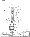
- the only figure shows a film blowing system with downstream stretching unit according to an embodiment of the present invention.
- the figure shows a device 10 according to the invention for the production of inline stretched tubular films in the blow molding process.
- the plastic granules to be processed are fed to an extruder 12 via a dosing device, melted in this, homogenized and fed to a film blowing head 14 .
- the film blowing head 14 has an annular nozzle from which the extruded plastic mass emerges. Cooling air for blowing up a tubular film 16 is supplied through the film blowing head.
- the tubular film 16 is kept in shape by a calibrating head 18 during the blowing process.
- the tubular film 16 is laid flat in a flattening unit 20 and, after the flattening unit, is fed directly to a stretching unit 22 arranged above the film blowing head 14 .
- the stretching unit is arranged on a platform 24 which lies above the flattening unit 20 .
- the still warm tubular film 16 fed flat from the flattening unit 20 is monoaxially stretched in the machine direction.
- the correspondingly stretched film is then continuously drawn off via a turning take-off 24 arranged above the stretching unit 22 and fed to a winder 28 via various rollers 26 and wound up to form film rolls.
- a stretching force of approximately 100 N to 1000 N is applied by overfeeding a roller.
- the rollers are at least partially heated in order to smooth the tubular film 16 during stretching.
- a corresponding stretching unit usually has to have at least one stretching gap.
- all of the rollers of the stretching unit 22 are individually driven and temperature-controlled. Like here in the figure 1 indicated, the rollers each have a different diameter, with the stretching rollers having a comparatively smaller diameter.
- nip rollers, ie counter rollers can also be provided in the stretching unit 22 .
- the rollers in the stretching unit 22 advantageously have a non-stick coating.
- the respective stretching gaps can also advantageously be adjustable.
- a temperature of ⁇ 10 °C below the glass transition temperature is usually set via the heating rollers.
- four rolls without a take-off nip with a wrap angle of more than 60° C. or preferably even more than 90° C. can be provided in the stretching unit.
- the stretching unit 22 is set up vertically. According to an alternative embodiment, which is not shown here, it can also be mounted transversely on the platform 24 .
- the torque of the rollers in the stretching unit is set in such a way that a certain regulated web tension factor is set.
- a knife or several knives are present above the stretching unit, which make the trimming for the so-called trimming.
- the edge areas which are made comparatively thicker than the middle areas as a result of the stretching, are cut away.
- the device for producing inline stretched tubular films presented here according to FIG 10 2013 007 669 has already been described in detail.
- an in figure 1 manner not shown also a profile measurement at the correspondingly necessary points, as for example in the DE 10 2013 007 669 have been described.
Description
Die vorliegende Erfindung betrifft eine Vorrichtung zur Herstellung von inline gereckten Schlauchfolien im Blasverfahren nach dem Oberbegriff des Anspruchs 1.The present invention relates to a device for the production of inline stretched tubular films in the blow molding process according to the preamble of claim 1.
Zur Herstellung von Schlauchfolien im Blasverfahren dienen üblicherweise Blasfolienextrusionsanlagen, die bereits seit langer Zeit im Einsatz sind. Solchen Anlagen werden Kunststoffe in granulierter Form zugeführt, die dann in Extrudern unter hohen Druckeinwirkungen zu einer viskosen Masse plastifiziert werden. Diese Masse, die aufgrund des Druckes eine hohe Temperatur aufweist, wird in einem Blaskopf ringförmig ausgebildet und entweicht dem Blaskopf durch eine Ringdüse. Unmittelbar nach dem Verlassen der Ringdüse bildet die Masse bereits einen Folienschlauch. Dieser Folienschlauch kann jedoch, da er noch nicht vollständig abgekühlt ist, in seinem Durchmesser verändert werden. In der Regel wird der Durchmesser vergrößert, indem in den Innenraum des Folienschlauchs Druckluft eingeblasen wird. Damit der Folienschlauch immer einen konstanten Durchmesser aufweist, wird er auf Abstand zu oder direkt entlang von Folienführungselementen geführt. Diese Anordnung der Folienführungselemente wird auf dem Gebiet der Blasfolienextrusionsanlagen als Kalibrierkorb bezeichnet.Blown film extrusion systems, which have been in use for a long time, are usually used to produce tubular films using the blow molding process. Such plants are supplied with plastics in granulated form, which are then plasticized in extruders under high pressure to form a viscous mass. This mass, which has a high temperature due to the pressure, is formed into a ring in a blow head and escapes from the blow head through an annular nozzle. Immediately after leaving the ring die, the mass forms a film tube. However, since it has not yet completely cooled down, the diameter of this tubular film can be changed. As a rule, the diameter is increased by blowing compressed air into the interior of the film tube. So that the film tube always has a constant diameter, it is guided at a distance from or directly along film guide elements. This arrangement of the film guide elements is referred to as a calibration basket in the field of blown film extrusion systems.
Nach dem Durchlaufen des Kalibrierkorbs, kann der Folienschlauch in einem reversierenden Wendeabzug flachgelegt, verlegt und anschließend in einer Reckanlage monoaxial in Maschinenrichtung verstreckt werden.After passing through the calibration basket, the tubular film can be flattened in a reversing take-off, laid and then monoaxially stretched in the machine direction in a stretching system.
Mit dem Recken von thermoplastischen Folien können deren Eigenschaften gezielt verändert werden. Solche Eigenschaften sind beispielsweise die Transparenz oder die Festigkeit. Ein solches Recken, das in Quer- und/oder Längsrichtung der Folienbahn erfolgen kann, kann direkt nach dem Extrusionsprozess inline erfolgen. Das Recken bzw.- Verstrecken von thermoplastischen Folien ist beispielsweise in der
Bei der Herstellung von Schlauchfolien kommen Foliendickenprofilregelsysteme mit segmentierten Regelzonen zum Einsatz. Durch diese Systeme lassen sich die Foliendickenprofile derart regeln, dass die Dickenabweichungen über den gesamten Schlauchumfang möglichst gering sind.Film thickness profile control systems with segmented control zones are used in the production of tubular films. With these systems, the film thickness profiles can be regulated in such a way that the thickness deviations over the entire circumference of the hose are as small as possible.
Aus der
Bei der Längsverstreckung in einer Reckanlage wird die Folie entsprechend des Reckgrades in Maschinenrichtung gedehnt und dadurch die Foliendicke reduziert. Gleichzeitig schnürt die Folie in Querrichtung ein, wodurch sich die Breite der Folie verringert. Diese Einschnürung hat zur Folge, dass die gereckte Folie von der Folienmitte in Richtung der Folienränder zunehmend geringfügiger dicker wird, obwohl sie zuvor im Blasverfahren auf eine möglichst konstante Dicke geregelt wurde. Besonders ausgeprägt ist diese Dickenzunahme an den Folienrandbereichen. Dieses verursacht beim anschließenden Aufwickeln der Folie einen Kantenaufbau in Foliendicke. Die Folienbahn wird an den Rändern mit zunehmendem Wickeldurchmesser immer mehr gedehnt.During longitudinal stretching in a stretching system, the film is stretched in the machine direction according to the degree of stretching, thereby reducing the film thickness. At the same time, the film constricts in the transverse direction, which reduces the width of the film. The consequence of this constriction is that the stretched film becomes increasingly slightly thicker from the center of the film in the direction of the film edges, although it was previously regulated to a thickness which is as constant as possible in the blow molding process. This increase in thickness is particularly pronounced at the edge areas of the film. When the film is subsequently wound up, this causes an edge build-up in the thickness of the film. The film web is stretched more and more at the edges as the winding diameter increases.
Um Folien mit möglichst gleichmäßigem Dickenprofil, wie sie insbesondere zum Bedrucken oder Laminieren gefordert werden, herzustellen, müssen die Folienränder, die dem gewünschten Dickenprofil nicht entsprechen, weggeschnitten werden. Durch dieses als Besäumen bezeichnetes Wegschneiden geht allerdings ein Großteil der Folienbreite verloren. So fallen auf jeder Seite der Folie bis ca. 200 mm durch das Besäumen, d. h. das Wegschneiden weg.In order to produce films with a thickness profile that is as uniform as possible, as is required in particular for printing or laminating, the film edges that do not correspond to the desired thickness profile must be cut away. However, a large part of the film width is lost as a result of this cutting away, known as trimming. Up to approx. 200 mm fall on each side of the film due to the trimming, i. H. cutting away.
Aus der
Bei den vorbekannten Vorrichtungen zur Herstellung von inline gereckten Schlauchfolien im Blasverfahren ist üblicherweise der reversierende Wendeabzug oberhalb des Extruders der Flachlegeeinheit nachgeschaltet. Die Schlauchfolie wird vom Wendeabzug aus üblicherweise an die neben dem Extruder angeordnete Reckanlage weitergefördert und dort entsprechend gereckt, bevor sie auf einem Wickler aufgewickelt wird. Ein derartiger Aufbau ergibt sich beispielsweise aus der
Nachteilig bei dieser Anordnung ist es allerdings, dass die flachgelegte, verlegte und über den reversierenden Wendeabzug abgezogene Schlauchfolie zu dem Zeitpunkt, zu dem sie in die Reckanlage eingeführt wird, schon soweit abgekühlt ist, dass sie zum Recken über zumindest eine Aufheizwalze noch auf eine für das Recken vorteilhafte Betriebstemperatur aufgeheizt werden muss. Dies hat insbesondere energetische Nachteile, da hier die Aufheizenergie nochmals zur Verfügung gestellt werden muss.The disadvantage of this arrangement, however, is that the tubular film, which has been laid flat, laid and pulled off via the reversing turning take-off, has already cooled down to the point at which it is introduced into the stretching system so that it can be stretched over at least one heating roller on a for the stretching advantageous operating temperature must be heated. This has energy disadvantages in particular, since the heating energy has to be made available again here.
Aufgabe der Erfindung ist es daher, eine gattungsgemäße Vorrichtung zur Herstellung von inline gereckten Schlauchfolien im Blasverfahren, insbesondere in energetischer Hinsicht zu optimieren, d. h. den Energiebedarf zur Herstellung zu senken.The object of the invention is therefore to provide a generic To optimize a device for the production of inline stretched tubular films in the blow molding process, in particular with regard to energy, ie to reduce the energy requirement for production.
Erfindungsgemäß wird diese Aufgabe durch eine Vorrichtung mit der Merkmalskombination des Anspruchs 1 gelöst. Hierzu weist eine Vorrichtung zur Herstellung von inline gereckten Schlauchfolien im Blasverfahren einen Extruder, eine Folienblasanlage, eine Flachlegeeinheit, einen reversierenden Wendeabzug und eine Reckanlage zur monoaxialen Verstreckung der flachgelegten Folie in Maschinenrichtung auf. Allerdings ist die Reckanlage oberhalb des Extruders zwischen der Flachlegeeinheit und dem reversierenden Wendeabzug angeordnet. Das bedeutet, dass die vom Extruder stammende Folie nach dem entsprechenden Flachlegen in der Flachlegeeinheit noch recht warm ist bis sie in die Reckanlage eingeführt wird. Hierdurch kann man zumindest die erste Aufheizwalze einsparen. Die noch warme Folie kann über das Reckwerk in gewünschter Weise verstreckt werden. Dabei ist zwar zur Temperierung immer noch ein weiteres Aufheizen notwendig. Dieses Aufheizen dient aber nur zum genauen Einstellen der Temperatur, da sich die aus dem Extruder und der Flachlegeeinheit kommende Schlauchfolie noch im wesentlich nahe der gewünschten Verarbeitungstemperatur befindet.According to the invention, this object is achieved by a device with the combination of features of claim 1. For this purpose, a device for producing inline stretched tubular films in the blow molding process has an extruder, a film blowing system, a flattening unit, a reversing turning take-off and a stretching system for monoaxial stretching of the flattened film in the machine direction. However, the stretching system is arranged above the extruder between the flattening unit and the reversing turning take-off. This means that the film from the extruder is still quite warm after it has been flattened in the flattening unit until it is fed into the stretching system. In this way one can save at least the first heating roller. The film, which is still warm, can be stretched in the desired manner via the stretching unit. It is true that further heating is still necessary for tempering. However, this heating only serves to set the temperature precisely, since the tubular film coming out of the extruder and the flattening unit is still essentially close to the desired processing temperature.
Weitere vorteilhafte Ausgestaltungen der Erfindung ergeben sich aus den sich an den Hauptanspruch anschließenden Unteransprüchen.Further advantageous refinements of the invention result from the dependent claims which follow the main claim.
Vorteilhaft ist die Reckanlage zusammen mit dem ihr in Förderrichtung nachgeschalteten Wendeabzug oberhalb der Flachlegeeinheit auf einer Plattform drehbar gelagert.Advantageously, the stretching system is rotatably mounted on a platform above the flattening unit together with the turning take-off downstream of it in the conveying direction.
Vorteilhaft sind auf der Plattform neben der Reckanlage auch noch weitere Komponenten, wie beispielsweise elektrische Umrichter und/oder Komponenten elektrischer Einspeisung und/oder Antriebe angeordnet. Die Anordnung ist so gewählt, dass hier ein Gewichtsausgleich auf der Plattform erfolgt.In addition to the stretching system, other components such as electrical converters and/or components of electrical feed and/or drives are also advantageously arranged on the platform. The arrangement is chosen so that the weight is balanced on the platform.
Für die zentrale Strom- und Wasserversorgung oberhalb der Plattform können Schleifringe bzw. eine Wasserdrehdurchführung vorgesehen sein. Vorteilhaft können auch die Kommunikationskabel als Datenleitung auf die Plattform geführt sein.Slip rings or a rotary water feedthrough can be provided for the central power and water supply above the platform. Advantageously, the communication cable can also be routed to the platform as a data line.
Oberhalb der Plattform sind an verschiedenen Positionen vorteilhaft Beobachtungssysteme in Form von Kameras angeordnet. Hier kann auf ein jeweiliges Aufsteigen auf die Plattform durch das Bedienpersonal verzichtet werden.Observation systems in the form of cameras are advantageously arranged at various positions above the platform. Here, the operating personnel do not have to climb onto the platform.
Die Walzen der Reckanlage sind vorteilhaft einzeln angetrieben und temperierbar. Die Walzen bilden mindestens einen Reckspalt, wobei dieser vorteilhaft verstellbar ist. Die Walzen der Reckanlage können unterschiedliche Durchmesser aufweisen, wobei die Reckwalzen einen vergleichsweise kleineren Durchmesser aufweisen.The rollers of the stretching system are advantageously individually driven and temperature-controlled. The rollers form at least one stretching gap, which is advantageously adjustable. The rollers of the stretching system can have different diameters, with the stretching rollers having a comparatively smaller diameter.
Vorteilhaft können die Walzen der Reckanlage eine Antihaftbeschichtung aufweisen.The rollers of the stretching system can advantageously have a non-stick coating.
Besonders vorteilhaft können die Walzen der Reckanlage so ausgeführt sein, dass durch Voreilen zumindest einer Walze eine Reckkraft von 100 N bis 1000 N aufbringbar ist.Particularly advantageously, the rollers of the stretching system can be designed in such a way that a stretching force of 100 N to 1000 N can be applied by advancing at least one roller.
Zum Temperieren der Walzen des Reckwerkes können mindestens zwei Temperierkreise, nämlich ein Heizkreis und ein Kühlkreis, vorhanden sein. Dabei kann die durch das Reckwerk geführte Blasfolie mittels der temperierten Walzen auf eine Temperatur aufgeheizt werden, die mindestens 10 °C unterhalb der Glastemperatur des Schlauchfolienmaterials liegt. Wesentlich ist gemäß einer weiteren bevorzugten Ausgestaltung, dass die temperierten Walzen über die Walzenbreite eine Temperaturgleichmäßigkeit von < 5 °C, vorzugsweise < 1 °C aufweist.At least two temperature control circuits, namely a heating circuit and a cooling circuit, can be present to control the temperature of the rollers of the stretching unit. The blown film guided through the stretching unit can be heated to a temperature that is at least 10° C. below the glass transition temperature of the tubular film material by means of the temperature-controlled rollers. According to a further preferred embodiment, it is essential that the tempered rollers have a temperature uniformity of <5° C., preferably <1° C., over the roller width.
Besonders vorteilhaft sind im Reckwerk auch Nipwalzen vorgesehen, die vorzugsweise eine andere Oberflächenbeschaffenheit aufweisen als die genippten Walzen.In a particularly advantageous manner, nip rollers are also provided in the stretching unit, which preferably have a different surface finish than the nipped rollers.
Zur Energieeinsparung sind erfindungsgemäß zwischen den antreibenden und bremsenden Walzen im Reckwerk jeweils Zwischenkreiskopplungen vorgesehen, die vorzugsweise als elektrische Kopplungen ausgebildet sind.In order to save energy, according to the invention intermediate circuit couplings are provided between the driving and braking rollers in the stretching unit, which are preferably designed as electrical couplings.
Anstelle der dem Reckwerk nachgeschalteten Reversiervorrichtung könnte auch vorgesehen sein, dass diese in der Reckvorrichtung selbst dadurch ausgebildet wird, dass die Annealingwalzen in der Reckvorrichtung reversierend am oberen Bereich der Reckvorrichtung ausgebildet sind.Instead of the reversing device downstream of the stretching unit, it could also be provided that this is formed in the stretching device itself by the annealing rollers in the stretching device being formed in a reversing manner in the upper area of the stretching device.
Weitere Merkmale, Einzelheiten und Vorteile der Erfindung werden anhand eines in der Zeichnung dargestellten Ausführungsbeispiels näher erläutert.Further features, details and advantages of the invention are explained in more detail using an exemplary embodiment illustrated in the drawing.
Die einzige Figur zeigt eine Folienblasanlage mit nachgeschaltetem Reckwerk nach einer Ausführungsform der vorliegenden Erfindung.The only figure shows a film blowing system with downstream stretching unit according to an embodiment of the present invention.
In der Figur ist eine erfindungsgemäße Vorrichtung 10 zur Herstellung von inline gereckten Schlauchfolien im Blasverfahren dargestellt. Über eine Dosiervorrichtung wird das zu verarbeitende Kunststoffgranulat einem Extruder 12 zugeführt, in diesem aufgeschmolzen, homogenisiert und einem Folienblaskopf 14 zugeführt. Der Folienblaskopf 14 weist eine Ringdüse auf, aus der die extrudierte Kunststoffmasse austritt. Durch den Folienblaskopf erfolgt die Zuleitung von Kühlluft zum Aufblasen einer Schlauchfolie 16. Die Schlauchfolie 16 wird durch einen Kalibrierkopf 18 während des Blasvorgangs in Form gehalten.The figure shows a
Nach dem Erstarren des Kunststoffs wird die Schlauchfolie 16 in einer Flachlegeeinheit 20 flachgelegt und nach der Flachlegeeinheit unmittelbar einem oberhalb des Folienblaskopfs 14 angeordneten Reckwerks 22 zugeführt. Das Reckwerk ist auf einer Plattform 24, die oberhalb der Flachlegeeinheit 20 liegt, angeordnet. Hier wird die noch warme aus der Flachlegeeinheit 20 flachgelegt zugeführte Schlauchfolie 16 monoaxial in Maschinenrichtung verstreckt. Die entsprechend verstreckte Folie wird dann über einen oberhalb des Reckwerks 22 angeordneten Wendeabzug 24 kontinuierlich abgezogen und über diverse Walzen 26 einem Wickler 28 zugeführt und zu Folienwickeln aufgewickelt.After the plastic has solidified, the
Im Reckwerk 22 wird durch Voreilung einer Walze eine Reckkraft von ca. 100 N bis 1000 N aufgebracht. Die Walzen sind zumindest teilweise beheizt, um die Schlauchfolie 16 während des Reckens zu glätten.In the stretching
Im hier dargestellten Reckwerk 22 sind vier Reckspalte gezeigt. Üblicherweise muss ein entsprechendes Reckwerk mindestens einen Reckspalt aufweisen. In der hier dargestellten Ausführungsvariante sind alle Walzen des Reckwerks 22 einzeln angetrieben und temperierbar. Wie hier in der
Vorteilhaft weisen die Walzen im Reckwerk 22 eine Antihaftbeschichtung auf. Die jeweiligen Reckspalte können ebenfalls vorteilhaft verstellbar sein. Üblicherweise wird über die Heizwalzen eine Temperatur von < 10 °C unterhalb der Glastemperatur eingestellt. In einer Ausführungsvariante können im Reckwerk vier Walzen ohne Abzugsnip mit einem Umschlingungswinkel von mehr als 60 °C oder vorzugsweise sogar mehr als 90 °C vorgesehen sein.The rollers in the stretching
Im hier dargestellten Ausführungsbeispiel nach
Im Rahmen der Erfindung ist im Reckwerk das Drehmoment der Walzen so eingestellt, dass ein bestimmter geregelter Bahnzugfaktor eingestellt wird. In hier nicht dargestellter Weise sind oberhalb des Reckwerks ein Messer oder mehrere Messer vorhanden, die den Beschnitt zur sogenannten Besäumung vornehmen. Hier werden die Randbereiche, die durch das Recken vergleichsweise dicker als die mittleren Bereiche ausgebildet sind, weggeschnitten. Um aber den Verlust durch das Abschneiden der verdickten Randbereiche zu minimieren, ist in der hier gemäß Figur 1 vorgestellten Vorrichtung zur Herstellung von inline gereckten Schlauchfolien vorteilhaft eine Profilregelung zur Vergleichmäßigung der Foliendicke über den gesamten Bereich der Folienbreite vorgesehen, wie sie beispielsweise anhand der deutschen Patentanmeldung
Claims (12)
- Device for producing tubular films stretched in-line in a blowing method, comprising an extruder (12), a film blowing system (14), a flattening unit (20), an oscillating haul-off unit (25) and a stretching system (22) for mono-axially stretching the flat lying film in a machine direction,
characterized in that
the stretching system is arranged above the extruder between the flattening unit and the oscillating haul-off unit, and that an intermediate circuit coupling, preferably an electrical coupling, is provided between driving and braking rollers in the stretching unit in order to save energy. - Device according to Claim 1, characterized in that the stretching system is rotatably mounted together with the haul-off unit downstream from it in the conveying direction above the flattening unit on a platform.
- Device according to Claim 2, characterized in that in addition to the stretching system further components, such as, for example, electrical converters and/or components of the electrical feed and/or drives, are arranged on the platform.
- Device according to Claim 2 or 3, characterized in that slip rings or a water rotary feedthrough are provided above the platform for the central power and water supply and/or that a communication cable is routed to the platform as a data line.
- Device according to any one of Claims 1 to 4, characterized in that monitoring systems, preferably cameras, are arranged above the platform at different positions.
- Device according to any one of the preceding claims, characterized in that the rollers of the stretching system are individually driven and can be temperature-controlled and that the rollers form at least one stretching gap, wherein the latter is advantageously adjustable.
- Device according to any one of the preceding claims, characterized in that the rollers of the stretching system have different diameters, wherein the stretching rollers have a comparatively smaller diameter.
- Device according to any one of the preceding claims, characterized in that the rollers of the stretching system have an anti-adhesive coating.
- Device according to any one of the preceding claims, characterized in that the rollers of the stretching system are designed such that due to the advantages of at least one roller a stretching force of 100 to 1000 N can be applied.
- Device according to any one of the preceding claims, characterized in that at least two temperature-control circuits, namely a heating circuit and a cooling circuit, are available for the temperature control of the rollers of the stretching unit.
- Device according to any one of the preceding claims, characterized in that the blown film routed through the stretching unit is heated up by means of the temperature-controlled rollers to a temperature which is at least 10 degrees below the glass temperature of the tubular film material.
- Device according to any one of the preceding claims, characterized in that the temperature-controlled rollers have a uniform temperature over the roller width of < 5 degrees Celsius, preferably < 1 degree Celsius.
Applications Claiming Priority (2)
| Application Number | Priority Date | Filing Date | Title |
|---|---|---|---|
| DE201310012134 DE102013012134A1 (en) | 2013-07-19 | 2013-07-19 | Device for producing inline stretched films |
| PCT/EP2014/001528 WO2015007356A1 (en) | 2013-07-19 | 2014-06-05 | Device for producing films stretched in-line |
Publications (3)
| Publication Number | Publication Date |
|---|---|
| EP3022040A1 EP3022040A1 (en) | 2016-05-25 |
| EP3022040B1 EP3022040B1 (en) | 2018-02-21 |
| EP3022040B2 true EP3022040B2 (en) | 2022-08-03 |
Family
ID=50897532
Family Applications (1)
| Application Number | Title | Priority Date | Filing Date |
|---|---|---|---|
| EP14728836.9A Active EP3022040B2 (en) | 2013-07-19 | 2014-06-05 | Device for producing films stretched in-line |
Country Status (5)
| Country | Link |
|---|---|
| US (1) | US20160151950A1 (en) |
| EP (1) | EP3022040B2 (en) |
| CN (1) | CN105408088A (en) |
| DE (2) | DE102013012134A1 (en) |
| WO (1) | WO2015007356A1 (en) |
Families Citing this family (9)
| Publication number | Priority date | Publication date | Assignee | Title |
|---|---|---|---|---|
| DE102013012134A1 (en) † | 2013-07-19 | 2015-01-22 | Windmöller & Hölscher Kg | Device for producing inline stretched films |
| DE102016101668A1 (en) * | 2016-01-29 | 2017-08-03 | Windmöller & Hölscher Kg | Perforation of foil edges |
| DE102016012389A1 (en) * | 2016-10-18 | 2018-04-19 | Reifenhäuser GmbH & Co. KG Maschinenfabrik | Blown film plant and method for operating a blown film plant for producing a thermoplastic material web |
| DE102016012469A1 (en) | 2016-10-18 | 2018-04-19 | Reifenhäuser GmbH & Co. KG Maschinenfabrik | Method and apparatus for determining a thickness distribution system of a doubly flattened film web, method for adjusting the film thickness profile of a doubled flattened film web, use of a method of adjusting a film thickness profile, and blown film equipment for producing a doubly flattened film web |
| US11628610B2 (en) | 2017-02-08 | 2023-04-18 | Cryovac, Llc | Process for in-line inspection of functional film layer containing detectable component |
| CN110352124A (en) * | 2017-02-08 | 2019-10-18 | 克里奥瓦克公司 | Method and system for on-line inspection of functional thin film layers containing detectable components |
| EP3647345A1 (en) | 2018-11-05 | 2020-05-06 | Windmöller & Hölscher KG | Breathable thermoplastic film with reduced shrinkage |
| US11584111B2 (en) | 2018-11-05 | 2023-02-21 | Windmoeller & Hoelscher Kg | Breathable thermoplastic film with reduced shrinkage |
| CN113087947A (en) * | 2021-04-20 | 2021-07-09 | 浙江众成包装材料股份有限公司 | High-beta-crystal-content polyvinylidene fluoride unidirectional stretching film and preparation method thereof |
Citations (27)
| Publication number | Priority date | Publication date | Assignee | Title |
|---|---|---|---|---|
| US2920352A (en) † | 1954-04-23 | 1960-01-12 | Du Pont | Process of casting and stretching film |
| US2976567A (en) † | 1957-10-16 | 1961-03-28 | Dow Chemical Co | Process and apparatus for upgrading thermoplastic film |
| GB922084A (en) † | 1958-05-16 | 1963-03-27 | Union Carbide Corp | Improvements in and relating to the production of film and tubing of organic thermoplastic material |
| DE1548243A1 (en) † | 1965-04-27 | 1969-04-24 | Industrial Nucleonics Corp | Method and device for measuring and regulating the rotational changes of a characteristic size, e.g. the thickness of plastic films |
| CH521219A (en) † | 1970-10-23 | 1972-04-15 | Windmoeller & Hoelscher | Device for the production of tubular plastic films |
| DE2146266A1 (en) † | 1971-09-16 | 1973-06-28 | Breuer Gmbh | Tubular film - with short distance between squeeze and stretching rollers |
| DE3508626C1 (en) † | 1985-03-11 | 1986-02-27 | Windmöller & Hölscher, 4540 Lengerich | Flat lay and take-off device for a tubular film web made of plastic in a blowing process |
| EP0065278B1 (en) † | 1981-05-14 | 1987-01-07 | Feldmühle Aktiengesellschaft | Transparent shrinkable film consisting of one or more layers |
| DE8707626U1 (en) † | 1987-05-27 | 1987-08-13 | Alpine Ag, 8900 Augsburg, De | |
| DE3518155C2 (en) † | 1985-05-21 | 1987-11-12 | Reifenhaeuser Gmbh & Co Maschinenfabrik, 5210 Troisdorf, De | |
| EP0335411A2 (en) † | 1988-03-31 | 1989-10-04 | Idemitsu Petrochemical Co. Ltd. | Method of and apparatus for manufacturing biaxially oriented film |
| EP0486858A1 (en) † | 1990-11-19 | 1992-05-27 | WindmÀ¶ller & Hölscher | Apparatus for measuring the thickness of a blown tubular film in a blow moulding system |
| DE4218997C1 (en) † | 1992-06-10 | 1994-01-20 | Reifenhaeuser Masch | Appts. for prodn. of plastic film from extrude blown tubing - produces close tolerances by dividing cooling system into segments of circumference of blowing nozzle each with finely controlled valve |
| US5288441A (en) † | 1992-12-24 | 1994-02-22 | Collins Steven L | System and method for extruder frost line detection |
| EP0673750A1 (en) † | 1994-03-18 | 1995-09-27 | Reifenhäuser GmbH & Co. Maschinenfabrik | Device for flattening a blown tubular thermoplastic film |
| US5458841A (en) † | 1991-09-06 | 1995-10-17 | Illinois Tool Works Inc. | Method for making prestretched film |
| US5912022A (en) † | 1996-03-12 | 1999-06-15 | Windmoller & Holscher | Device to lay flat a film tube |
| US6241502B1 (en) † | 1997-04-24 | 2001-06-05 | Klaus Reinhold Maschinen- Und Geraetebau Gmbh | Take-off apparatus for plastic tubular sheets |
| US6413346B1 (en) † | 1998-05-18 | 2002-07-02 | Macro Engineering & Technology Inc. | Production of stretch plastic film |
| US6447278B1 (en) † | 1998-05-26 | 2002-09-10 | Polymer Processing, Inc. | Apparatus for processing blown tube films |
| WO2005102666A1 (en) † | 2004-04-14 | 2005-11-03 | Windmöller & Hölscher Kg | Device for conveying a tubular film |
| EP1707338A1 (en) † | 2005-03-27 | 2006-10-04 | Huhtamaki Forchheim Zweigniederlassung der Huhtamaki Deutschland GmbH & Co. KG | Process for the production of an oriented plastic film |
| DE102005035750A1 (en) † | 2005-05-23 | 2006-11-30 | Windmöller & Hölscher Kg | Deflection device for a film web |
| WO2007006472A1 (en) † | 2005-07-13 | 2007-01-18 | Windmöller & Hölscher Kg | Blown film manufacturing installation and method for the operation thereof |
| DE102011018320A1 (en) † | 2011-04-20 | 2012-10-25 | Hosokawa Alpine Ag | Method for regulating the thickness of blown films |
| DE102012015462A1 (en) † | 2012-08-07 | 2014-02-13 | Reifenhäuser GmbH & Co. KG Maschinenfabrik | Blown film plant, process for producing a blown film web and film produced therewith |
| DE102013012134A1 (en) † | 2013-07-19 | 2015-01-22 | Windmöller & Hölscher Kg | Device for producing inline stretched films |
Family Cites Families (10)
| Publication number | Priority date | Publication date | Assignee | Title |
|---|---|---|---|---|
| DE3002903C2 (en) * | 1980-01-28 | 1986-12-04 | Windmöller & Hölscher, 4540 Lengerich | Method for controlling the film thickness on a blown film extruder |
| DE3324978C2 (en) * | 1983-07-11 | 1985-10-17 | Windmöller & Hölscher, 4540 Lengerich | Lay-flat and take-off device for a plastic tubular film web produced by a blown blown film die head |
| CN1011212B (en) * | 1986-06-03 | 1991-01-16 | 四川省涪陵地区塑料三厂 | Method for manufacturing polyvinyl alcohol film by blow moulding with biaxially oriented stretching under mormal temp |
| DE3941185A1 (en) | 1989-12-13 | 1991-06-20 | Windmoeller & Hoelscher | METHOD FOR REGULATING THE FILM THICKNESS OF TUBE FILMS PRODUCED BY BLOW PROCESSING AND AXIAL, PREFERRED BIAXIAL |
| US5441395A (en) * | 1994-06-22 | 1995-08-15 | Planeta; Mirek | Tubular plastic film extrusion apparatus with improved adjustable sizing cage |
| DE202004019456U1 (en) | 2004-12-16 | 2005-12-29 | Brückner Maschinenbau GmbH | Device for driving a Vorheizwalzenanordnung in a plant for the production of films |
| DE102009033171B4 (en) | 2009-07-13 | 2016-03-03 | Hosokawa Alpine Ag | Method for controlling the film thickness of stretched tubular films and apparatus for carrying out the method |
| DE102009046585A1 (en) | 2009-11-10 | 2011-05-19 | Windmöller & Hölscher Kg | Apparatus and method for longitudinally stretching a film web |
| DE102009046592A1 (en) * | 2009-11-10 | 2011-05-12 | Windmöller & Hölscher Kg | Apparatus and method for longitudinally stretching a film web |
| DE102013007669A1 (en) | 2013-05-02 | 2014-11-06 | Windmöller & Hölscher Kg | Method for controlling the thickness profile of inline stretched films |
-
2013
- 2013-07-19 DE DE201310012134 patent/DE102013012134A1/en active Pending
- 2013-07-19 DE DE202013012784.8U patent/DE202013012784U1/en active Active
-
2014
- 2014-06-05 WO PCT/EP2014/001528 patent/WO2015007356A1/en active Application Filing
- 2014-06-05 EP EP14728836.9A patent/EP3022040B2/en active Active
- 2014-06-05 CN CN201480040806.1A patent/CN105408088A/en active Pending
- 2014-06-05 US US14/905,577 patent/US20160151950A1/en not_active Abandoned
Patent Citations (30)
| Publication number | Priority date | Publication date | Assignee | Title |
|---|---|---|---|---|
| US2920352A (en) † | 1954-04-23 | 1960-01-12 | Du Pont | Process of casting and stretching film |
| US2976567A (en) † | 1957-10-16 | 1961-03-28 | Dow Chemical Co | Process and apparatus for upgrading thermoplastic film |
| GB922084A (en) † | 1958-05-16 | 1963-03-27 | Union Carbide Corp | Improvements in and relating to the production of film and tubing of organic thermoplastic material |
| DE1548243A1 (en) † | 1965-04-27 | 1969-04-24 | Industrial Nucleonics Corp | Method and device for measuring and regulating the rotational changes of a characteristic size, e.g. the thickness of plastic films |
| CH521219A (en) † | 1970-10-23 | 1972-04-15 | Windmoeller & Hoelscher | Device for the production of tubular plastic films |
| US3804572A (en) † | 1970-10-23 | 1974-04-16 | Windmoeller & Hoelscher | Apparatus for making tubular plastics film by means of a blowhead |
| DE2146266A1 (en) † | 1971-09-16 | 1973-06-28 | Breuer Gmbh | Tubular film - with short distance between squeeze and stretching rollers |
| EP0065278B1 (en) † | 1981-05-14 | 1987-01-07 | Feldmühle Aktiengesellschaft | Transparent shrinkable film consisting of one or more layers |
| DE3508626C1 (en) † | 1985-03-11 | 1986-02-27 | Windmöller & Hölscher, 4540 Lengerich | Flat lay and take-off device for a tubular film web made of plastic in a blowing process |
| DE3518155C2 (en) † | 1985-05-21 | 1987-11-12 | Reifenhaeuser Gmbh & Co Maschinenfabrik, 5210 Troisdorf, De | |
| DE8707626U1 (en) † | 1987-05-27 | 1987-08-13 | Alpine Ag, 8900 Augsburg, De | |
| EP0335411A2 (en) † | 1988-03-31 | 1989-10-04 | Idemitsu Petrochemical Co. Ltd. | Method of and apparatus for manufacturing biaxially oriented film |
| EP0486858A1 (en) † | 1990-11-19 | 1992-05-27 | WindmÀ¶ller & Hölscher | Apparatus for measuring the thickness of a blown tubular film in a blow moulding system |
| US5458841A (en) † | 1991-09-06 | 1995-10-17 | Illinois Tool Works Inc. | Method for making prestretched film |
| DE69208002T2 (en) † | 1991-09-06 | 1996-06-27 | Illinois Tool Works | Process for producing a stretch packaging film |
| DE4218997C1 (en) † | 1992-06-10 | 1994-01-20 | Reifenhaeuser Masch | Appts. for prodn. of plastic film from extrude blown tubing - produces close tolerances by dividing cooling system into segments of circumference of blowing nozzle each with finely controlled valve |
| US5288441A (en) † | 1992-12-24 | 1994-02-22 | Collins Steven L | System and method for extruder frost line detection |
| EP0673750A1 (en) † | 1994-03-18 | 1995-09-27 | Reifenhäuser GmbH & Co. Maschinenfabrik | Device for flattening a blown tubular thermoplastic film |
| US5912022A (en) † | 1996-03-12 | 1999-06-15 | Windmoller & Holscher | Device to lay flat a film tube |
| US6241502B1 (en) † | 1997-04-24 | 2001-06-05 | Klaus Reinhold Maschinen- Und Geraetebau Gmbh | Take-off apparatus for plastic tubular sheets |
| US6413346B1 (en) † | 1998-05-18 | 2002-07-02 | Macro Engineering & Technology Inc. | Production of stretch plastic film |
| US6447278B1 (en) † | 1998-05-26 | 2002-09-10 | Polymer Processing, Inc. | Apparatus for processing blown tube films |
| WO2005102666A1 (en) † | 2004-04-14 | 2005-11-03 | Windmöller & Hölscher Kg | Device for conveying a tubular film |
| EP1707338A1 (en) † | 2005-03-27 | 2006-10-04 | Huhtamaki Forchheim Zweigniederlassung der Huhtamaki Deutschland GmbH & Co. KG | Process for the production of an oriented plastic film |
| DE102005035750A1 (en) † | 2005-05-23 | 2006-11-30 | Windmöller & Hölscher Kg | Deflection device for a film web |
| WO2007006472A1 (en) † | 2005-07-13 | 2007-01-18 | Windmöller & Hölscher Kg | Blown film manufacturing installation and method for the operation thereof |
| DE102011018320A1 (en) † | 2011-04-20 | 2012-10-25 | Hosokawa Alpine Ag | Method for regulating the thickness of blown films |
| DE102012015462A1 (en) † | 2012-08-07 | 2014-02-13 | Reifenhäuser GmbH & Co. KG Maschinenfabrik | Blown film plant, process for producing a blown film web and film produced therewith |
| EP2849929A1 (en) † | 2012-08-07 | 2015-03-25 | Reifenhäuser GmbH & Co. KG Maschinenfabrik | Blown film installation, method for producing a blown film strip and film produced therewith |
| DE102013012134A1 (en) † | 2013-07-19 | 2015-01-22 | Windmöller & Hölscher Kg | Device for producing inline stretched films |
Also Published As
| Publication number | Publication date |
|---|---|
| DE202013012784U1 (en) | 2019-08-02 |
| CN105408088A (en) | 2016-03-16 |
| DE102013012134A1 (en) | 2015-01-22 |
| EP3022040A1 (en) | 2016-05-25 |
| WO2015007356A1 (en) | 2015-01-22 |
| US20160151950A1 (en) | 2016-06-02 |
| EP3022040B1 (en) | 2018-02-21 |
Similar Documents
| Publication | Publication Date | Title |
|---|---|---|
| EP3022040B2 (en) | Device for producing films stretched in-line | |
| EP2991816B1 (en) | Method for regulating the thickness profile of inline-oriented films | |
| EP1558437B1 (en) | Extrusion of peroxidic cross-linkable molded plastic parts | |
| DE2528370C3 (en) | Process for producing biaxially stretched film webs made of plastic and device for carrying out the process | |
| DE102009033171A1 (en) | Method for controlling the thickness of stretched blown film | |
| EP2347878B1 (en) | Method for producing peroxide-networked polyethylene tubes in an extrusion line | |
| EP2809496B1 (en) | Stretching device and method for elongating a film web | |
| EP4041526A1 (en) | Method for starting or terminating production of a film in a film machine, film machine and computer program product | |
| DE3217039C2 (en) | Process for producing a biaxially oriented film and device for carrying out the process | |
| EP3302928B1 (en) | Device and method for cooling a blown film | |
| DE202013012786U1 (en) | Device for producing inline stretched films | |
| DE102012112491A1 (en) | Device and method for producing plastic preforms made of a thermoplastic material | |
| DE2162229B2 (en) | Method and device for feeding raw materials into the shear gap of machines for producing films, webs, foils or plates made of plastic | |
| WO2021074181A1 (en) | Device for producing inline-oriented tubular films in a blowing process | |
| DE102013100719A1 (en) | Method for continuous production of plastic composite pipe, involves winding impregnated cloth tape around core tube, utilizing strips for forming wall of tube, and applying coating over outer surface of finished tube | |
| DE102012112357B4 (en) | Process for manufacturing a belt from plasticizable plastic material | |
| DE102020131010A1 (en) | BLOWED FILM PLANT AND METHOD FOR MANUFACTURING A BLOWED FILM | |
| DE102020127196A1 (en) | BLOWN FILM PLANT, PROCESS FOR MANUFACTURING A BLOW MOLDED FILM, AND THE FILM PRODUCED WITH IT | |
| DE102004017952B4 (en) | Device for transporting a film tube | |
| EP4041524A1 (en) | Blown film installation and method for producing tubular films or film webs | |
| DE202013012785U1 (en) | Device for producing inline stretched films | |
| DE102019215782A1 (en) | Blown film line and method for producing a film web | |
| DE102019107335A1 (en) | DEVICE AND METHOD FOR PRODUCING A FILM COVER | |
| DE2363117C3 (en) | Use of thermoplastic tubular films as loading goods for calenders | |
| DE3890850C2 (en) |
Legal Events
| Date | Code | Title | Description |
|---|---|---|---|
| PUAI | Public reference made under article 153(3) epc to a published international application that has entered the european phase |
Free format text: ORIGINAL CODE: 0009012 |
|
| 17P | Request for examination filed |
Effective date: 20151103 |
|
| AK | Designated contracting states |
Kind code of ref document: A1 Designated state(s): AL AT BE BG CH CY CZ DE DK EE ES FI FR GB GR HR HU IE IS IT LI LT LU LV MC MK MT NL NO PL PT RO RS SE SI SK SM TR |
|
| AX | Request for extension of the european patent |
Extension state: BA ME |
|
| TPAC | Observations filed by third parties |
Free format text: ORIGINAL CODE: EPIDOSNTIPA |
|
| DAX | Request for extension of the european patent (deleted) | ||
| GRAP | Despatch of communication of intention to grant a patent |
Free format text: ORIGINAL CODE: EPIDOSNIGR1 |
|
| STAA | Information on the status of an ep patent application or granted ep patent |
Free format text: STATUS: GRANT OF PATENT IS INTENDED |
|
| INTG | Intention to grant announced |
Effective date: 20171025 |
|
| GRAS | Grant fee paid |
Free format text: ORIGINAL CODE: EPIDOSNIGR3 |
|
| GRAA | (expected) grant |
Free format text: ORIGINAL CODE: 0009210 |
|
| STAA | Information on the status of an ep patent application or granted ep patent |
Free format text: STATUS: THE PATENT HAS BEEN GRANTED |
|
| AK | Designated contracting states |
Kind code of ref document: B1 Designated state(s): AL AT BE BG CH CY CZ DE DK EE ES FI FR GB GR HR HU IE IS IT LI LT LU LV MC MK MT NL NO PL PT RO RS SE SI SK SM TR |
|
| REG | Reference to a national code |
Ref country code: GB Ref legal event code: FG4D Free format text: NOT ENGLISH |
|
| REG | Reference to a national code |
Ref country code: CH Ref legal event code: EP |
|
| REG | Reference to a national code |
Ref country code: DE Ref legal event code: R096 Ref document number: 502014007331 Country of ref document: DE Ref country code: AT Ref legal event code: REF Ref document number: 971231 Country of ref document: AT Kind code of ref document: T Effective date: 20180315 |
|
| REG | Reference to a national code |
Ref country code: IE Ref legal event code: FG4D Free format text: LANGUAGE OF EP DOCUMENT: GERMAN |
|
| REG | Reference to a national code |
Ref country code: DE Ref legal event code: R026 Ref document number: 502014007331 Country of ref document: DE |
|
| PLBI | Opposition filed |
Free format text: ORIGINAL CODE: 0009260 |
|
| 26 | Opposition filed |
Opponent name: REIFENHAEUSER GMBH & CO. KG MASCHINENFABRIK Effective date: 20180423 |
|
| REG | Reference to a national code |
Ref country code: NL Ref legal event code: MP Effective date: 20180221 |
|
| REG | Reference to a national code |
Ref country code: LT Ref legal event code: MG4D |
|
| PG25 | Lapsed in a contracting state [announced via postgrant information from national office to epo] |
Ref country code: FI Free format text: LAPSE BECAUSE OF FAILURE TO SUBMIT A TRANSLATION OF THE DESCRIPTION OR TO PAY THE FEE WITHIN THE PRESCRIBED TIME-LIMIT Effective date: 20180221 Ref country code: NO Free format text: LAPSE BECAUSE OF FAILURE TO SUBMIT A TRANSLATION OF THE DESCRIPTION OR TO PAY THE FEE WITHIN THE PRESCRIBED TIME-LIMIT Effective date: 20180521 Ref country code: CY Free format text: LAPSE BECAUSE OF FAILURE TO SUBMIT A TRANSLATION OF THE DESCRIPTION OR TO PAY THE FEE WITHIN THE PRESCRIBED TIME-LIMIT Effective date: 20180221 Ref country code: ES Free format text: LAPSE BECAUSE OF FAILURE TO SUBMIT A TRANSLATION OF THE DESCRIPTION OR TO PAY THE FEE WITHIN THE PRESCRIBED TIME-LIMIT Effective date: 20180221 Ref country code: NL Free format text: LAPSE BECAUSE OF FAILURE TO SUBMIT A TRANSLATION OF THE DESCRIPTION OR TO PAY THE FEE WITHIN THE PRESCRIBED TIME-LIMIT Effective date: 20180221 Ref country code: LT Free format text: LAPSE BECAUSE OF FAILURE TO SUBMIT A TRANSLATION OF THE DESCRIPTION OR TO PAY THE FEE WITHIN THE PRESCRIBED TIME-LIMIT Effective date: 20180221 Ref country code: HR Free format text: LAPSE BECAUSE OF FAILURE TO SUBMIT A TRANSLATION OF THE DESCRIPTION OR TO PAY THE FEE WITHIN THE PRESCRIBED TIME-LIMIT Effective date: 20180221 |
|
| PG25 | Lapsed in a contracting state [announced via postgrant information from national office to epo] |
Ref country code: GR Free format text: LAPSE BECAUSE OF FAILURE TO SUBMIT A TRANSLATION OF THE DESCRIPTION OR TO PAY THE FEE WITHIN THE PRESCRIBED TIME-LIMIT Effective date: 20180522 Ref country code: RS Free format text: LAPSE BECAUSE OF FAILURE TO SUBMIT A TRANSLATION OF THE DESCRIPTION OR TO PAY THE FEE WITHIN THE PRESCRIBED TIME-LIMIT Effective date: 20180221 Ref country code: BG Free format text: LAPSE BECAUSE OF FAILURE TO SUBMIT A TRANSLATION OF THE DESCRIPTION OR TO PAY THE FEE WITHIN THE PRESCRIBED TIME-LIMIT Effective date: 20180521 Ref country code: LV Free format text: LAPSE BECAUSE OF FAILURE TO SUBMIT A TRANSLATION OF THE DESCRIPTION OR TO PAY THE FEE WITHIN THE PRESCRIBED TIME-LIMIT Effective date: 20180221 Ref country code: SE Free format text: LAPSE BECAUSE OF FAILURE TO SUBMIT A TRANSLATION OF THE DESCRIPTION OR TO PAY THE FEE WITHIN THE PRESCRIBED TIME-LIMIT Effective date: 20180221 |
|
| PG25 | Lapsed in a contracting state [announced via postgrant information from national office to epo] |
Ref country code: MT Free format text: LAPSE BECAUSE OF FAILURE TO SUBMIT A TRANSLATION OF THE DESCRIPTION OR TO PAY THE FEE WITHIN THE PRESCRIBED TIME-LIMIT Effective date: 20180221 |
|
| PG25 | Lapsed in a contracting state [announced via postgrant information from national office to epo] |
Ref country code: EE Free format text: LAPSE BECAUSE OF FAILURE TO SUBMIT A TRANSLATION OF THE DESCRIPTION OR TO PAY THE FEE WITHIN THE PRESCRIBED TIME-LIMIT Effective date: 20180221 Ref country code: PL Free format text: LAPSE BECAUSE OF FAILURE TO SUBMIT A TRANSLATION OF THE DESCRIPTION OR TO PAY THE FEE WITHIN THE PRESCRIBED TIME-LIMIT Effective date: 20180221 Ref country code: RO Free format text: LAPSE BECAUSE OF FAILURE TO SUBMIT A TRANSLATION OF THE DESCRIPTION OR TO PAY THE FEE WITHIN THE PRESCRIBED TIME-LIMIT Effective date: 20180221 Ref country code: AL Free format text: LAPSE BECAUSE OF FAILURE TO SUBMIT A TRANSLATION OF THE DESCRIPTION OR TO PAY THE FEE WITHIN THE PRESCRIBED TIME-LIMIT Effective date: 20180221 |
|
| PG25 | Lapsed in a contracting state [announced via postgrant information from national office to epo] |
Ref country code: SK Free format text: LAPSE BECAUSE OF FAILURE TO SUBMIT A TRANSLATION OF THE DESCRIPTION OR TO PAY THE FEE WITHIN THE PRESCRIBED TIME-LIMIT Effective date: 20180221 Ref country code: DK Free format text: LAPSE BECAUSE OF FAILURE TO SUBMIT A TRANSLATION OF THE DESCRIPTION OR TO PAY THE FEE WITHIN THE PRESCRIBED TIME-LIMIT Effective date: 20180221 Ref country code: SM Free format text: LAPSE BECAUSE OF FAILURE TO SUBMIT A TRANSLATION OF THE DESCRIPTION OR TO PAY THE FEE WITHIN THE PRESCRIBED TIME-LIMIT Effective date: 20180221 Ref country code: CZ Free format text: LAPSE BECAUSE OF FAILURE TO SUBMIT A TRANSLATION OF THE DESCRIPTION OR TO PAY THE FEE WITHIN THE PRESCRIBED TIME-LIMIT Effective date: 20180221 |
|
| PLAX | Notice of opposition and request to file observation + time limit sent |
Free format text: ORIGINAL CODE: EPIDOSNOBS2 |
|
| REG | Reference to a national code |
Ref country code: CH Ref legal event code: PL |
|
| GBPC | Gb: european patent ceased through non-payment of renewal fee |
Effective date: 20180605 |
|
| PG25 | Lapsed in a contracting state [announced via postgrant information from national office to epo] |
Ref country code: SI Free format text: LAPSE BECAUSE OF FAILURE TO SUBMIT A TRANSLATION OF THE DESCRIPTION OR TO PAY THE FEE WITHIN THE PRESCRIBED TIME-LIMIT Effective date: 20180221 |
|
| REG | Reference to a national code |
Ref country code: BE Ref legal event code: MM Effective date: 20180630 |
|
| REG | Reference to a national code |
Ref country code: IE Ref legal event code: MM4A |
|
| PG25 | Lapsed in a contracting state [announced via postgrant information from national office to epo] |
Ref country code: MC Free format text: LAPSE BECAUSE OF FAILURE TO SUBMIT A TRANSLATION OF THE DESCRIPTION OR TO PAY THE FEE WITHIN THE PRESCRIBED TIME-LIMIT Effective date: 20180221 Ref country code: LU Free format text: LAPSE BECAUSE OF NON-PAYMENT OF DUE FEES Effective date: 20180605 |
|
| PLBB | Reply of patent proprietor to notice(s) of opposition received |
Free format text: ORIGINAL CODE: EPIDOSNOBS3 |
|
| PG25 | Lapsed in a contracting state [announced via postgrant information from national office to epo] |
Ref country code: IE Free format text: LAPSE BECAUSE OF NON-PAYMENT OF DUE FEES Effective date: 20180605 Ref country code: GB Free format text: LAPSE BECAUSE OF NON-PAYMENT OF DUE FEES Effective date: 20180605 Ref country code: CH Free format text: LAPSE BECAUSE OF NON-PAYMENT OF DUE FEES Effective date: 20180630 Ref country code: LI Free format text: LAPSE BECAUSE OF NON-PAYMENT OF DUE FEES Effective date: 20180630 Ref country code: FR Free format text: LAPSE BECAUSE OF NON-PAYMENT OF DUE FEES Effective date: 20180630 |
|
| PG25 | Lapsed in a contracting state [announced via postgrant information from national office to epo] |
Ref country code: BE Free format text: LAPSE BECAUSE OF NON-PAYMENT OF DUE FEES Effective date: 20180630 |
|
| PG25 | Lapsed in a contracting state [announced via postgrant information from national office to epo] |
Ref country code: TR Free format text: LAPSE BECAUSE OF FAILURE TO SUBMIT A TRANSLATION OF THE DESCRIPTION OR TO PAY THE FEE WITHIN THE PRESCRIBED TIME-LIMIT Effective date: 20180221 |
|
| PG25 | Lapsed in a contracting state [announced via postgrant information from national office to epo] |
Ref country code: PT Free format text: LAPSE BECAUSE OF FAILURE TO SUBMIT A TRANSLATION OF THE DESCRIPTION OR TO PAY THE FEE WITHIN THE PRESCRIBED TIME-LIMIT Effective date: 20180221 |
|
| PG25 | Lapsed in a contracting state [announced via postgrant information from national office to epo] |
Ref country code: HU Free format text: LAPSE BECAUSE OF FAILURE TO SUBMIT A TRANSLATION OF THE DESCRIPTION OR TO PAY THE FEE WITHIN THE PRESCRIBED TIME-LIMIT; INVALID AB INITIO Effective date: 20140605 Ref country code: MK Free format text: LAPSE BECAUSE OF NON-PAYMENT OF DUE FEES Effective date: 20180221 |
|
| PLAB | Opposition data, opponent's data or that of the opponent's representative modified |
Free format text: ORIGINAL CODE: 0009299OPPO |
|
| PG25 | Lapsed in a contracting state [announced via postgrant information from national office to epo] |
Ref country code: IS Free format text: LAPSE BECAUSE OF FAILURE TO SUBMIT A TRANSLATION OF THE DESCRIPTION OR TO PAY THE FEE WITHIN THE PRESCRIBED TIME-LIMIT Effective date: 20180621 |
|
| REG | Reference to a national code |
Ref country code: AT Ref legal event code: MM01 Ref document number: 971231 Country of ref document: AT Kind code of ref document: T Effective date: 20190605 |
|
| R26 | Opposition filed (corrected) |
Opponent name: REIFENHAEUSER GMBH & CO. KG MASCHINENFABRIK Effective date: 20180423 |
|
| PG25 | Lapsed in a contracting state [announced via postgrant information from national office to epo] |
Ref country code: AT Free format text: LAPSE BECAUSE OF NON-PAYMENT OF DUE FEES Effective date: 20190605 |
|
| APBM | Appeal reference recorded |
Free format text: ORIGINAL CODE: EPIDOSNREFNO |
|
| APBP | Date of receipt of notice of appeal recorded |
Free format text: ORIGINAL CODE: EPIDOSNNOA2O |
|
| APAH | Appeal reference modified |
Free format text: ORIGINAL CODE: EPIDOSCREFNO |
|
| APBU | Appeal procedure closed |
Free format text: ORIGINAL CODE: EPIDOSNNOA9O |
|
| PUAH | Patent maintained in amended form |
Free format text: ORIGINAL CODE: 0009272 |
|
| STAA | Information on the status of an ep patent application or granted ep patent |
Free format text: STATUS: PATENT MAINTAINED AS AMENDED |
|
| 27A | Patent maintained in amended form |
Effective date: 20220803 |
|
| AK | Designated contracting states |
Kind code of ref document: B2 Designated state(s): AL AT BE BG CH CY CZ DE DK EE ES FI FR GB GR HR HU IE IS IT LI LT LU LV MC MK MT NL NO PL PT RO RS SE SI SK SM TR |
|
| REG | Reference to a national code |
Ref country code: DE Ref legal event code: R102 Ref document number: 502014007331 Country of ref document: DE |
|
| PGFP | Annual fee paid to national office [announced via postgrant information from national office to epo] |
Ref country code: DE Payment date: 20230630 Year of fee payment: 10 |
|
| PGFP | Annual fee paid to national office [announced via postgrant information from national office to epo] |
Ref country code: IT Payment date: 20230620 Year of fee payment: 10 |