EP3020998B2 - Scheibenbremse - Google Patents
Scheibenbremse Download PDFInfo
- Publication number
- EP3020998B2 EP3020998B2 EP15003114.4A EP15003114A EP3020998B2 EP 3020998 B2 EP3020998 B2 EP 3020998B2 EP 15003114 A EP15003114 A EP 15003114A EP 3020998 B2 EP3020998 B2 EP 3020998B2
- Authority
- EP
- European Patent Office
- Prior art keywords
- brake
- shaft
- dimension
- disc
- brake shaft
- Prior art date
- Legal status (The legal status is an assumption and is not a legal conclusion. Google has not performed a legal analysis and makes no representation as to the accuracy of the status listed.)
- Active
Links
Images


Classifications
-
- F—MECHANICAL ENGINEERING; LIGHTING; HEATING; WEAPONS; BLASTING
- F16—ENGINEERING ELEMENTS AND UNITS; GENERAL MEASURES FOR PRODUCING AND MAINTAINING EFFECTIVE FUNCTIONING OF MACHINES OR INSTALLATIONS; THERMAL INSULATION IN GENERAL
- F16D—COUPLINGS FOR TRANSMITTING ROTATION; CLUTCHES; BRAKES
- F16D65/00—Parts or details
- F16D65/14—Actuating mechanisms for brakes; Means for initiating operation at a predetermined position
- F16D65/16—Actuating mechanisms for brakes; Means for initiating operation at a predetermined position arranged in or on the brake
- F16D65/18—Actuating mechanisms for brakes; Means for initiating operation at a predetermined position arranged in or on the brake adapted for drawing members together, e.g. for disc brakes
-
- F—MECHANICAL ENGINEERING; LIGHTING; HEATING; WEAPONS; BLASTING
- F16—ENGINEERING ELEMENTS AND UNITS; GENERAL MEASURES FOR PRODUCING AND MAINTAINING EFFECTIVE FUNCTIONING OF MACHINES OR INSTALLATIONS; THERMAL INSULATION IN GENERAL
- F16D—COUPLINGS FOR TRANSMITTING ROTATION; CLUTCHES; BRAKES
- F16D65/00—Parts or details
- F16D65/0043—Brake maintenance and assembly, tools therefor
-
- F—MECHANICAL ENGINEERING; LIGHTING; HEATING; WEAPONS; BLASTING
- F16—ENGINEERING ELEMENTS AND UNITS; GENERAL MEASURES FOR PRODUCING AND MAINTAINING EFFECTIVE FUNCTIONING OF MACHINES OR INSTALLATIONS; THERMAL INSULATION IN GENERAL
- F16D—COUPLINGS FOR TRANSMITTING ROTATION; CLUTCHES; BRAKES
- F16D2121/00—Type of actuator operation force
- F16D2121/14—Mechanical
-
- F—MECHANICAL ENGINEERING; LIGHTING; HEATING; WEAPONS; BLASTING
- F16—ENGINEERING ELEMENTS AND UNITS; GENERAL MEASURES FOR PRODUCING AND MAINTAINING EFFECTIVE FUNCTIONING OF MACHINES OR INSTALLATIONS; THERMAL INSULATION IN GENERAL
- F16D—COUPLINGS FOR TRANSMITTING ROTATION; CLUTCHES; BRAKES
- F16D2125/00—Components of actuators
- F16D2125/18—Mechanical mechanisms
- F16D2125/20—Mechanical mechanisms converting rotation to linear movement or vice versa
- F16D2125/22—Mechanical mechanisms converting rotation to linear movement or vice versa acting transversely to the axis of rotation
- F16D2125/28—Cams; Levers with cams
Definitions
- the invention relates to a disc brake according to the preamble of claim 1.
- Disc brakes of the above type are known, for example from the DE10219148 C1 or the DE 44 16 175 A1 .
- Comparable brakes are known from the EP 1 944 522 A1 , the US 5 772 366 A and the DE 36 10 569 A1 .
- Numerous brake manufacturers and distributors offer brakes that are intended for different applications or vehicle types. While the calipers of these brakes are often the same, the brakes differ in the respective brake shafts inside the caliper.
- brake shafts can differ from one another in that they result in different gear ratios when the brake is applied. These different gear ratios, as well as other differences, determine whether the brake is suitable for a certain application or for a certain vehicle type. Since several brake shafts are designed to work together with the relevant caliper, i.e. can theoretically be used to apply the brake, it is not noticeable when assembling the brake if the wrong brake shaft is installed in view of the intended application.
- the invention is therefore based on the object of reliably preventing such incorrect installation.
- the installation opening creates a type of coding that allows only the brake shaft that is appropriate for the intended application to be installed, whereas another brake shaft cannot be installed in the caliper because of the installation opening that serves as the coding, even if it may be so matched to the brake caliper that it could at least theoretically be used to apply the brake.
- This prevents, for example, a brake shaft with the wrong gear ratio from being installed in a brake caliper.
- coding is used to prevent an incorrect brake shaft from being installed in the caliper. This is done because the coding ensures that only the brake shaft that is suitable for the intended application can and will be installed.
- the installation opening has a first dimension in a first direction and a second dimension in a second direction transverse to the first direction and the brake shaft has a first dimension in the first direction that is smaller than the first dimension of the installation opening and/or has a second dimension in the second direction that is smaller than the second dimension of the installation opening.
- the coding is realized by the dimensions of the installation opening on the one hand and the brake shaft on the other.
- the first direction is perpendicular to the second direction.
- the brake shaft can be an eccentric shaft that rests on a wall of the brake caliper and presses a brake shoe against a brake disc when rotated.
- the wall is located in the area of the caliper facing away from the brake disc and is therefore at the rear and is formed in one piece with the caliper, i.e. not in the form of a cover or the like, which has mechanical, particularly strength, advantages.
- the brake shaft is further preferably part of a rotary lever and/or an axis of rotation of the brake shaft is parallel to a main plane of a brake disc.
- the assembly of a brake must be carried out particularly carefully because a brake is a safety-relevant component. It is therefore advantageous to inspect individual components and their position after installation in the brake calliper.
- the invention provides that a pre-assembled unit comprising the brake shaft in combination with a pressure piece, with a pressure spindle device and/or with a bearing device does not fit through the insertion opening.
- the pressure piece could make it difficult or even impossible to inspect the position of the brake shaft within the caliper after installation if it were installed as a pre-assembled unit together with the brake shaft.
- the brake shaft only fits through the insertion opening in a predetermined rotational position, but after passing through the insertion opening inside the brake calliper it can be rotated for the purpose of applying the brake.
- the predetermined rotational position does not mean a specific value, but rather a rotational angle range that may be quite small.
- This design means that the brake shaft can be prevented from being inserted as a pre-assembled unit together with the pressure piece and/or a bearing device by means of the forced rotational position when it is inserted into the insertion opening. At the same time, however, the flexibility and rotatability of the brake shaft required for the brake to function is guaranteed.
- the above-mentioned coding can be implemented by means of one-piece areas of the brake caliper that determine the contour of the installation opening.
- a coding mask that at least partially determines the contour of the installation opening can also be provided, which is attached to the caliper in order to code the caliper, and can be removable or non-removable. This allows the caliper to be designed more universally, whereas it only acquires its individuality when the mask is attached.
- the installation opening preferably faces the brake disc in the assembled state.
- the caliper can be designed to be closed in the section facing away from the brake disc (rear), which has mechanical, particularly strength, advantages.
- This solution is also preferable to a solution in which the installation opening is not formed in the part of the brake caliper facing the brake disc (front), but rather on the side, top or bottom, because such an opening would also weaken the caliper mechanically.
- the opening facing the brake disc is required anyway, because the application device acts on the application-side brake shoes and thus on the brake disc through this opening.
- the brake calliper is preferably made in one piece.
- the application device is mounted in its interior. It is largely closed, particularly in the rear area, except for the required functional openings, with only one opening facing the brake disc through which the functional parts can be introduced into the interior in order to then form the application device as a whole.
- a rotary lever actuation with an eccentric effect is preferably used in order to convert an input force in the force flow area through the internal transmission via coupled pressure transmission means, such as a cross-member-shaped pressure piece and/or pressure spindle devices, into a significantly higher output force in the direction of the brake pad or the brake disc as braking force.
- the lever protrudes from the eccentrically acting brake shaft, at the end of which an actuating device such as an actuating cylinder engages in order to pivot the rotary lever with the brake shaft about an axis of rotation lying parallel to a brake disc plane.
- partial rotary bearings or support points of different designs are preferably provided to couple the functional parts together.
- the functional parts wrap around each other in sections, for example additionally via appropriately designed intermediate bearings, such as rotary and/or plain bearings.
- Disc brakes with a specific caliper size are often installed in different vehicle types. Since different braking performances are required for each vehicle type, the internal parts must also be designed accordingly. This requires changes to the part dimensions, in particular the internal brake ratio via the rotary lever/brake shaft.
- the rotary lever with its brake shaft contour is designed accordingly, i.e. the geometric contour is assigned to the brake for each application.
- the invention creates a way of preventing incorrect installation, in particular of the rotary lever in the interior of the caliper through the installation opening. In other words, it ensures that the correct rotary lever is safely assigned to the corresponding brake caliper and that the correct installation and functional position of the rotary lever in the brake caliper is also guaranteed.
- the invention provides in particular that there is a coding/encryption between the opening geometry/contour of said installation opening and the rotary lever/brake shaft contour, whereby the coding is achieved by various combinations of the geometry of the contact surfaces of the brake caliper on the one hand and the contact surfaces of the rotary lever on the other.
- Said contact surfaces in the form of projections are present and coordinated with one another in such a way that it is only possible to install the correct rotary lever in a defined position or spatial orientation in the corresponding brake caliper housing.
- this coding only works during the assembly process, which means that once the predefined installation position has been reached, the rotary lever is functional without any further measures.
- special coding areas between the rotary lever/brake shaft geometry are designed as projections, these can also be located in other positions relative to/under one another if this effectively prevents an incorrect rotary lever from being installed in a brake caliper. It does not matter how the rotary lever is designed as a whole and as an eccentrically acting camshaft and how it is supported/mounted relative to the end of the caliper.
- the invention provides in particular for a one-piece brake caliper.
- it can also be used for two- or multi-piece brake calipers, provided that the installation opening faces the brake disc.
- the invention provides in particular that the brake shaft or the rotary lever in combination with a pressure piece and/or with a bearing device, i.e. as a pre-assembled unit, does not fit through the insertion opening.
- the insertion opening is comparatively small. This reduces any possible weakening of the material compared to a larger installation opening. Material applications/thickening are therefore only required to a small extent or not at all. Such material applications/thickening are only possible to a limited extent or not at all in this area due to the lack of space with regard to other vehicle parts, such as wheel rims.
- the installation opening is too large, material deformations cannot be ruled out, so that the associated relative movements in the flange area between the brake calliper and the closure plate can lead to leaks. This is avoided with the installation opening, which is preferably smaller according to the invention.
- the feature of the "small" installation opening also fulfills another task, namely saddle stabilization via dimensional rigidity to improve functional reliability.
- the invention is equally applicable to single-spindle brakes and two- or multi-spindle brakes.
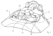
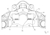
- the brake shown in the drawing includes a brake calliper 10 with guide rails 12, 14, 16, 18, 20, 22.
- the guide rails serve to guide a pressure piece 24.
- the pressure piece is cross-shaped.
- a pressure spindle device is designated by the reference number 26.
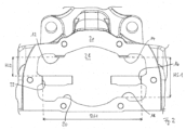
- the brake calliper 10 has an installation opening 28 facing the brake disc (not shown).
- the contour of the installation opening is determined, among other things, by the guide strips 12 to 22. Therefore, the guide strips also determine what fits through the insertion opening 28.
- a dimension between the guide strips 14 and 18 is designated HS1.
- a dimension between the guide strip 12 and an edge of the guide strip 22 is designated HS2.
- a dimension between the guide strips 16 and 22 is designated BS1.
- a flange running around the insertion opening 28 has the reference number 30.
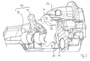
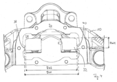
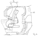
- the brake also includes a brake shaft 32, which together with an actuating lever 34 forms a rotary lever 36.
- Projections 38, 40 are formed on the two end faces of the brake shaft 32.
- a dimension between one side of the projection 40 and a boundary surface of the brake shaft 32 is designated HW1.
- the dimension between the respective free ends of the projections 38 and 40 is designated BW1.
- the dimension between the two end faces of the brake shaft 32 is designated BW2.
- the rotary lever 36 is arranged inside the saddle 10 when installed.
- Figure 3 shows the rotary lever 36 and the saddle 10 before installation.
- the rotary lever 36 or the brake shaft 32 cannot be installed through the insertion opening 28 in the saddle 10 because the two projections 38, 40 strike the guide rails 22 and 16 respectively.
- the dimension BW1 is namely larger than the dimension BS1.
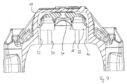
- Figure 8 Furthermore, it can be seen in particular that the guide rails 12 to 22 used for coding the brake calliper 10 also serve to guide the pressure piece 24.
- Figure 9 As can be seen, the length of the guide strips 12 to 22 is such that they do not affect the rotation of the brake shaft 32 or the rotary lever 36 in the installed state. In other words, the brake shaft 32 can also be rotated in the installed state in view of the projections 38, 40 without the projections striking the guide strips 12 to 22.
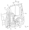
- Figure 10 shows not only the saddle 10 with the rotary lever 36 and the pressure piece 24 in the installed state, but also sliding and/or rotary bearings 42, 44 for coupling the brake shaft 32 with the pressure piece 24 on the one hand and the rear wall 46 of the saddle 10 on the other hand.
- the saddle 10 on the one hand and the rotary lever 36 on the other hand are "coded” by designing certain dimensions in such a way that the rotary lever 36 can be inserted into the interior of the saddle 10 through the insertion opening 28.
- the coding prevents the installation of a different rotary lever, for example a rotary lever with a different transmission ratio, although it could (theoretically) be used to apply the brake. This is achieved, for example, by different dimensioning of the dimensions described above, for example by different attachment of the projections 38, 40. This ensures that only the rotary shaft intended for the intended area of application is installed in the saddle 10 through the insertion opening 28.
- the insertion opening 28 is closed and sealed by a closure cover (not shown) having at least one functional opening for the passage of the at least one pressure spindle device in such a way that no agents that impair the function can penetrate into the interior of the caliper.
Landscapes
- Engineering & Computer Science (AREA)
- General Engineering & Computer Science (AREA)
- Mechanical Engineering (AREA)
- Braking Arrangements (AREA)
Description
- Die Erfindung betrifft eine Scheibenbremse nach dem Oberbegriff von Anspruch 1.
- Scheibenbremsen der oben genannten Art sind bekannt, beispielsweise aus der
DE10219148 C1 oder derDE 44 16 175 A1 . Vergleichbare Bremsen sind bekannt aus derEP 1 944 522 A1 , derUS 5 772 366 A und derDE 36 10 569 A1 . Zahlreiche Bremsenhersteller und -vertreiber bieten Bremsen an, die für unterschiedliche Einsatzgebiete bzw. Fahrzeugtypen gedacht sind. Während die Sättel dieser Bremsen häufig gleich sind, unterscheiden sich die Bremsen in den jeweiligen Bremswellen im Inneren des Sattels. So können sich beispielsweise Bremswellen dadurch voneinander unterscheiden, daß sie in unterschiedlichen Übersetzungsverhältnissen bei der Betätigung der Bremse resultieren. Diese unterschiedlichen Übersetzungsverhältnisse, aber auch andere Unterschiede, entscheiden darüber, ob die Bremse für ein bestimmtes Einsatzgebiet bzw. für einen bestimmten Fahrzeugtyp geeignet ist. Da mehrere Bremswellen von ihrer Auslegung her dazu geeignet sind, mit dem betreffenden Sattel zusammenzuwirken, d.h. theoretisch zum Zuspannen der Bremse dienen können, fällt es beim Zusammenbau der Bremse nicht auf, wenn angesichts des beabsichtigten Einsatzgebietes eine falsche Bremswelle eingebaut wird. - Der Erfindung liegt daher die Aufgabe zugrunde, einen solchen Falscheinbau zuverlässig zu verhindern.
- Erfindungsgemäß wird die gestellte Aufgabe durch eine Scheibenbremse nach Anspruch 1 gelöst.
- Mit anderen Worten wird über die Einbauöffnung eine Art Codierung geschaffen, die den Einbau nur der für das beabsichtigte Einsatzgebiet sachgemäßen Bremswelle erlaubt, wohingegen eine andere Bremswelle wegen der als Codierung dienenden Einbauöffnung nicht in den Sattel eingebaut werden kann, wenngleich sie derart auf den Bremssattel abgestimmt sein mag, daß sie zumindest theoretisch zum Zuspannen der Bremse dienen könnte. Auf diese Weise wird beispielsweise verhindert, daß eine Bremswelle mit dem falschen Übersetzungsverhältnis in einen Bremssattel eingebaut wird. Anders ausgedrückt wird eine Codierung verwendet, um den Fehleinbau einer nicht sachgemäßen Bremswelle in den Sattel zu verhindern. Dies geschieht dadurch, daß die Codierung dafür sorgt, daß eben nur die zu dem beabsichtigten Einsatzgebiet passende Bremswelle eingebaut werden kann und wird.
- Dabei fallen erfindungsgemäß eine Begrenzung der Einbauöffnung und eine Einrichtung zur Abstützung/Führung des Druckstücks zumindest abschnittweise zusammen. Es liegt also eine Doppelfunktion vor. Anders ausgedrückt wird ein Element zum Realisieren der oben erwähnten Codierung gleichzeitig zum Abstützen/Führen des Druckstücks verwendet. Dadurch kann die Teilezahl verringert werden. Erfindungsgemäß ist vorgesehen, daß die Einbauöffnung eine erste Abmessung in einer ersten Richtung und eine zweite Abmessung in einer quer zu der ersten Richtung liegenden zweiten Richtung hat und die Bremswelle in der ersten Richtung eine erste Abmessung hat, die kleiner als die erste Abmessung der Einbauöffnung ist, und/oder in der zweiten Richtung eine zweite Abmessung hat, die kleiner als die zweite Abmessung der Einbauöffnung ist.
- Wenn oben und im Folgenden von "Abmessung" die Rede ist, so ist damit jeweils eine Abmessung gemeint, die für die Frage relevant ist, ob die Bremswelle durch die Einbauöffnung paßt.
- Bei dieser Ausgestaltung wird eine für das beabsichtigte Einsatzgebiet ungeeignete Bremswelle bei dem Versuch des Einbaus in den Bremssattel an mindestens einer Stelle anschlagen, weshalb sie nicht durch die Eingangsöffnung paßt. Ein Fehleinbau ist damit vermieden.
- Mit anderen Worten wird bei dieser erfindungsgemäß bevorzugten Ausgestaltung die Codierung durch die Abmessungen der Einbauöffnung einerseits und der Bremswelle andererseits realisiert.
- Bevorzugt steht die erste Richtung senkrecht auf der zweiten Richtung.
- Bei der Bremswelle kann es sich um eine Exzenterwelle handeln, die sich an einer Wand des Bremssattels abstützt und bei Verdrehen einen Bremsbacken gegen eine Bremsscheibe drückt. Bevorzugt liegt die genannte Wand dabei im bremsscheibenabgewandten und damit hinteren Bereich des Sattels und ist einstückig mit dem Sattel, d.h. nicht in Form eines Deckels oder dergleichen ausgebildet, was mechanische, insbesondere Festigkeitsvorteile hat.
- Erfindungsgemäß weiter bevorzugt ist die Bremswelle Teil eines Drehhebels und/oder liegt eine Drehachse der Bremswelle parallel zu einer Hauptebene einer Bremsscheibe.
- Diese Ausgestaltung ist besonders zuverlässig und robust. Dies gilt insbesondere dann, wenn entsprechend einer bevorzugten Ausführungsform der Erfindung ein zusammen mit der Bremswelle den Drehhebel ausmachender (Betätigungs-)Hebel in eingebautem Zustand innerhalb des Bremssattels liegt.
- Der Zusammenbau einer Bremse muß besonders sorgfältig erfolgen, weil eine Bremse ein sicherheitsrelevantes Bauteil darstellt. Daher ist es vorteilhaft, einzelne Bauteile und ihre Lage nach Einbau in den Bremssattel zu inspizieren. Um dies insbesondere im Hinblick auf die Bremswelle zu ermöglichen, ist es erfindungsgemäß vorgesehen, daß eine die Bremswelle in Kombination mit einem Druckstück, mit einer Druckspindeleinrichtung und/oder mit einer Lagereinrichtung aufweisende vormontierte Einheit nicht durch die Einführöffnung paßt.
- Beispielsweise das Druckstück könnte nämlich eine Inspizierung der Lage der Bremswelle innerhalb des Sattels nach Einbau erschweren oder gar unmöglich machen, sofern es als vormontierte Einheit zusammen mit der Bremswelle eingebaut würde.
- Die Ausgestaltung, wonach die Bremswelle beispielsweise nicht zusammen mit dem Druckstück als vormontierte Einheit eingebaut werden kann, gewährleistet demgegenüber die Inspizierbarkeit der Bremswelle nach ihrem Einbau in den Sattel, und zwar bevor das Druckstück eingebaut wird.
- Insbesondere einem vergleichbaren Zweck dient die Tatsache, dass erfindungsgemäß die Bremswelle nur in einer vorbestimmten Drehstellung durch die Einführöffnung passt, nach Passieren der Einführöffnung im Inneren des Bremssattels jedoch für die Zwecke des Zuspannens der Bremse verdrehbar ist. Mit der vorbestimmten Drehstellung ist dabei kein punktueller Wert gemeint, sondern ein unter Umständen recht kleiner Drehwinkelbereich.
- Durch diese Ausgestaltung kann nämlich vermittels der erzwungenen Drehstellung beim Einführen in die Einführöffnung verhindert werden, daß die Bremswelle zusammen mit dem Druckstück und/oder einer Lagereinrichtung als vormontierte Einheit eingesetzt wird. Gleichzeitig ist aber die für die Funktion der Bremse erforderliche Flexibilität bzw. Verdrehbarkeit der Bremswelle gewährleistet.
- Die oben erwähnte Codierung kann erfindungsgemäß durch einstückige, die Kontur der Einbauöffnung bestimmende Bereiche des Bremssattels realisiert sein. Es kann aber auch eine die Kontur der Einbauöffnung zumindest teilweise bestimmende Codiermaske vorgesehen sein, die zum Codieren eines Sattels an dem Sattel angebracht wird, und zwar abnehmbar oder nicht abnehmbar. Dadurch kann der Sattel universeller ausgestaltet sein, wohingegen er seine Individualität erst durch Anbringen der Maske erhält.
- Die Einbauöffnung ist erfindungsgemäß bevorzugt in montiertem Zustand der Bremsscheibe zugewandt. Dadurch kann der Sattel in seinem bremsscheibenabgewandten (hinteren) Abschnitt geschlossen ausgeführt sein, was mechanische, insbesondere Festigkeitsvorteile hat. Diese Lösung ist auch einer Lösung vorzuziehen, bei der die Einbauöffnung nicht im bremsscheibenzugewandten (vorderen) Teil des Bremssattels, sondern seitlich, oben oder unten ausgebildet ist, weil auch eine solche Öffnung den Sattel mechanisch schwächen würde. Demgegenüber ist die bremsscheibenzugewandte Öffnung ohnehin erforderlich, weil durch diese Öffnung die Zuspanneinrichtung auf den zuspannseitigen Bremsbacken und damit auf die Bremsscheibe einwirkt.
- Der Bremssattel ist erfindungsgemäß bevorzugt einstückig. In seinem Inneren ist die Zuspanneinrichtung gelagert. Er ist insbesondere im rückwärtigen Bereich bis auf die erforderlichen Funktionsöffnungen weitestgehend geschlossen, wobei lediglich zur Bremsscheibe weisend eine Öffnung vorhanden ist, durch die die Funktionsteile in den Innenraum einführbar sind, um dort dann in der Gesamtheit die Zuspanneinrichtung zu bilden.
- Dabei wird erfindungsgemäß bevorzugt eine Drehhebelbetätigung mit einer exzentrischen Wirkung eingesetzt, um im Kraftflußbereich eine Eingangskraft durch die innere Übersetzung über angekoppelte Druckübertragungsmittel, wie beispielsweise ein traversenförmiges Druckstück und/oder Druckspindeleinrichtungen, in eine wesentlich höhere Ausgangskraft in Richtung des Bremsbelages bzw. der Bremsscheibe als Bremskraft umzusetzen. Dafür ragt aus der exzentrisch wirkenden Bremswelle der Hebel vor, an dessen Ende eine Betätigungseinrichtung wie beispielsweise ein Betätigungszylinder angreift, um den Drehhebel mit der Bremswelle um eine parallel zu einer Bremsscheibenebene liegende Drehachse zu verschwenken.
- Damit während des erforderlichen Bremshubes ein reibungsmindernder Kontakt im Kraftfluß vorhanden ist und um die Einbauräume im Sattelinneren zu optimieren, sind bevorzugt Teildrehlagerungen bzw. Abstützstellen unterschiedlicher Ausführung vorhanden, um die Funktionsteile miteinander zu koppeln. Dafür umschlingen sich die Funktionsteile in Teilabschnitten, beispielsweise zusätzlich noch über entsprechend ausgeführte Zwischenlager, wie beispielsweise Dreh- und/oder Gleitlagerungen.
- Häufig werden Scheibenbremsen mit einer bestimmten Sattelgröße im Fahrzeugeinsatz in unterschiedliche Fahrzeugtypen verbaut. Da je Fahrzeugtyp auch unterschiedliche Bremsenleistungen erforderlich sind, müssen die Innenteile auch dementsprechend ausgelegt werden. Dies erfordert Änderungen an der Teiledimensionierung, wie insbesondere die innere Bremsenübersetzung über Drehhebel/Bremswelle. Der Drehhebel mit seiner Bremswellenkontur wird dementsprechend ausgelegt, d.h. die geometrische Kontur ist je Einsatzfall der Bremse zugeordnet.
- Die Erfindung schafft eine Möglichkeit, einen Fehleinbau insbesondere des Drehhebels in den Sattelinnenraum durch die Einbauöffnung zu verhindern. Mit anderen Worten stellt sie sicher, daß der richtige Drehhebel dem entsprechenden Bremssattel sicher zugeordnet ist und daß auch die richtige Einbau- bzw. Funktionslage des Drehhebels im Bremssattel gewährleistet ist.
- Dazu sieht die Erfindung insbesondere vor, daß zwischen der Öffnungsgeometrie / -kontur besagter Einbauöffnung und der Drehhebel-/Bremswellenkontur eine Codierung/Verschlüsselung vorhanden ist, wobei die Codierung durch verschiedene Kombinationen der Geometrie der Anlageflächen des Bremssattels einerseits und der Anlageflächen des Drehhebels andererseits erreicht wird. Besagte Anlageflächen in Form von Vorsprüngen sind so vorhanden und auch so aufeinander abgestimmt, daß es nur möglich ist, den jeweils richtigen Drehhebel in einer definierten Position bzw. Raumlage in das dazu passende Bremssattelgehäuse einzubauen. Bevorzugt wirkt diese Codierung nur während des Montagevorgangs, was bedeutet, daß nach Erreichen der vordefinierten Einbauposition der Drehhebel ohne weitere Maßnahmen funktionsfähig ist.
- Wenngleich nach einer bevorzugten Ausführungsform der Erfindung spezielle Codierungsbereiche zwischen der Drehhebel-/Bremswellengeometrie als Vorsprünge ausgeführt sind, können diese auch an anderen Positionen zueinander/untereinander liegen, wenn damit wirkungsvoll verhindert wird, daß ein falscher Drehhebel in einen Bremssattel eingebaut wird. Dabei ist es gleichgültig, wie der Drehhebel in seiner Gesamtheit und als exzentrisch wirkende Nockenwelle ausgeführt und gegenüber dem Sattelende abgestützt/gelagert wird.
- Letztendlich kann die Einbaucodierung durch einzelne oder mehrere Maßnahmen realisiert werden, wie:
- Zusätzliches Bauteil zur Verbreiterung der Bremswelle, als Vorsprung wirkend,
- Variationen der Positionen der seitlichen Vorsprünge bzw. Führungsleisten im Bremssattelgehäuse und/oder
- Vorsprünge des Sattels, die in Vertiefungen der Bremswelle oder umgekehrt nach einem Nut/Federprinzip eingreifen.
- Wie bereits oben erläutert sieht die Erfindung insbesondere einen einteiligen Bremssattel vor. Sie ist aber auch auf zwei- oder mehrteilige Bremssättel anwendbar, sofern die Einbauöffnung bremsscheibenzugewandt liegt.
- Oben ist bereits erläutert worden, daß es nach der Erfindung insbesondere vorgesehen ist, daß die Bremswelle bzw. der Drehhebel in Kombination mit einem Druckstück und/oder mit einer Lagereinrichtung zusammen, also als vormontierte Einheit, nicht durch die Einführöffnung paßt. Mit anderen Worten ist die Einführöffnung vergleichsweise klein. Dadurch ist eine eventuelle Materialschwächung gegenüber einer größeren Einbauöffnung verringert. Materialaufträge/Aufdickungen sind daher in nur geringem Maße oder gar nicht erforderlich. Solche Materialaufträge/Aufdickungen sind nämlich in diesem Bereich wegen des Platzmangelns im Hinblick auf andere Fahrzeugteile, wie beispielsweise Radfelgen, nur begrenzt oder gar nicht möglich. Bei zu großer Einbauöffnung können daher Materialdeformationen nicht ausgeschlossen werden, so daß dann damit einhergehende Relativbewegungen im Flanschbereich zwischen Bremssattel und Verschlußplatte zu Undichtigkeiten führen können. Dies wird mit der erfindungsgemäß bevorzugt kleineren Einbauöffnung vermieden.
- Das Merkmal der "kleinen" Einbauöffnung erfüllt zusätzlich noch eine weitere Aufgabenstellung, nämlich eine Sattelstabilisierung über Formsteifigkeit zur Verbesserung der Funktionssicherheit.
- Die Erfindung ist gleichermaßen auf Einspindelbremsen und Zwei- oder Mehrspindelbremsen anwendbar.
- Im folgenden ist die Erfindung anhand eines bevorzugten Ausführungsbeispiels unter Bezugnahme auf die beiliegende Zeichnung mit weiteren Einzelheiten näher erläutert. Dabei zeigen
- Figur 1
- eine perspektivische Ansicht eines Bremssattels nach einer bevorzugten Ausführungsform der Erfindung,
- Figur 2
- eine teilweise geschnittene Ansicht des Sattels,
- Figur 3
- eine teilweise geschnittene Seitenansicht des Sattels mit einem Drehhebel in Explosions-Darstellung,
- Figur 4
- die gleiche Ansicht wie
Figur 2 , jedoch mit Drehhebel, - Figur 5
- die gleiche Ansicht wie
Figur 4 , jedoch in einem anderen Betriebszustand, - Figur 6
- eine teilweise geschnittene Ansicht des Sattels mit eingebautem Drehhebel,
- Figur 7
- eine teilweise geschnittene Draufsicht auf den Sattel mit eingebautem Drehhebel,
- Figur 8
- die gleiche Ansicht wie
Figur 4 , jedoch mit eingebautem Druckstück, - Figur 9
- die gleiche Ansicht wie
Figur 7 , jedoch mit eingebautem Druckstück und - Figur 10
- eine Seitenschnittansicht des Sattels mit eingebauter Zuspanneinrichtung.
- Zu der in der Zeichnung dargestellten Bremse gehört ein Bremssattel 10 mit Führungsleisten 12, 14, 16, 18, 20, 22. Die Führungsleisten dienen zum Führen eines Druckstücks 24. Das Druckstück ist bei diesem Ausführungsbeispiel traversenförmig. Eine Druckspindeleinrichtung ist mit der Bezugszahl 26 bezeichnet.
- Der Bremssattel 10 hat eine der (nicht gezeigten) Bremsscheibe zugewandte Einbauöffnung 28. Die Kontur der Einbauöffnung wird unter anderem von den Führungsleisten 12 bis 22 bestimmt. Daher sind es auch die Führungsleisten, die mitbestimmen, was durch die Einführöffnung 28 hindurchpaßt. Eine Abmessung zwischen den Führungsleisten 14 und 18 ist mit HS1 bezeichnet. Eine Abmessung zwischen der Führungsleiste 12 und einer Kante der Führungsleiste 22 ist mit HS2 bezeichnet. Eine Abmessung zwischen den Führungsleisten 16 und 22 ist mit BS1 bezeichnet. Ein die Einführöffnung 28 umlaufender Flansch trägt die Bezugszahl 30.
- Zu der Bremse gehört ferner eine Bremswelle 32, die zusammen mit einem Betätigungshebel 34 einen Drehhebel 36 bildet. An der Bremswelle 32 sind an den beiden Stirnseiten Vorsprünge 38, 40 ausgebildet. Eine Abmessung zwischen einer Seite des Vorsprungs 40 und einer Begrenzungsfläche der Bremswelle 32 ist mit HW1 bezeichnet. Die Abmessung zwischen den jeweiligen freien Enden der Vorsprünge 38 und 40 ist mit BW1 bezeichnet. Die Abmessung zwischen den beiden Stirnseiten der Bremswelle 32 ist mit BW2 bezeichnet.
- Wie insbesondere
Figur 10 zu entnehmen ist, ist der Drehhebel 36 in eingebautem Zustand innerhalb des Sattels 10 angeordnet. -
Figur 3 zeigt den Drehhebel 36 und den Sattel 10 vor dem Einbau. In der Stellung nachFigur 4 kann der Drehhebel 36 bzw. die Bremswelle 32 nicht durch die Einführöffnung 28 in den Sattel 10 eingebaut werden, weil die beiden Vorsprünge 38, 40 an den Führungsleisten 22 bzw. 16 anschlagen. Die Abmessung BW1 ist nämlich größer als die Abmessung BS1. - Erst wenn der Drehhebel 36 bzw. die Bremswelle 32 so verschwenkt wird, daß die Vorsprünge 38, 40 gemäß
Figur 5 oberhalb der Führungsleisten 16, 22 zu liegen kommen, kann der Drehhebel in den Innenraum des Bremssattels 10 eingeschoben werden. - In dieser Drehwinkelstellung, wie sie in
Figur 5 gezeigt ist, kann die Bremswelle 32 aber nicht in Kontakt mit dem Druckstück 24 sein bzw. mit dem Druckstück keine vormontierte Einheit bilden, weshalb die Bremswelle 32 bzw. der Drehhebel 36 nur ohne das Druckstück 24 in den Sattel 10 eingebaut werden kann. Diesen Zustand zeigtFigur 7 . In dem Betriebszustand nachFigur 7 kann die Einbaulage der Bremswelle 32 bzw. des Drehhebels 36 ungehindert inspiziert werden, insbesondere weil kein Druckstück die Sicht versperrt. - Anders bei dem Betriebszustand nach
Figur 8 . Hier ist das Druckstück 24 bereits montiert, weshalb die Bremswelle 32 nicht mehr zu sehen ist. Auch ist die Druckspindeleinrichtung 26 montiert. -
Figur 8 ist darüber hinaus insbesondere zu entnehmen, daß die der Codierung des Bremssattels 10 dienenden Führungsleisten 12 bis 22 gleichzeitig auch der Führung des Druckstücks 24 dienen. Wie aberFigur 9 zu entnehmen ist, ist die Länge der Führungsleisten 12 bis 22 derart bemessen, daß sie ein Verdrehen der Bremswelle 32 bzw. des Drehhebels 36 in eingebautem Zustand nicht beeinträchtigen. Mit anderen Worten kann die Bremswelle 32 auch angesichts der Vorsprünge 38, 40 in eingebautem Zustand verdreht werden, ohne daß die Vorsprünge an den Führungsleisten 12 bis 22 anschlagen würden. -
Figur 10 zeigt nicht nur den Sattel 10 mit dem Drehhebel 36 und dem Druckstück 24 in eingebautem Zustand, sondern auch Gleit- und/oder Drehlagerungen 42, 44 zum Koppeln der Bremswelle 32 mit dem Druckstück 24 einerseits und der rückwärtigen Wand 46 des Sattels 10 andererseits. - Wie oben im einzelnen erläutert ist, sind der Sattel 10 einerseits und der Drehhebel 36 andererseits durch Ausgestaltung bestimmter Abmessungen derart "codiert", daß der Drehhebel 36 durch die Einführöffnung 28 in das Innere des Sattels 10 eingeführt werden kann. Demgegenüber ist wegen der Codierung der Einbau eines anderen Drehhebels, beispielsweise eines Drehhebels mit einem anderen Übersetzungsverhältnis ausgeschlossen, obwohl er (theoretisch) zum Zuspannen der Bremse dienen könnte. Dies wird beispielsweise durch eine andere Dimensionierung der oben beschriebenen Abmessungen erreicht, so beispielsweise durch eine andere Anbringung der Vorsprünge 38, 40. Dadurch ist gewährleistet, daß nur die für das beabsichtigte Einsatzgebiet vorgesehene Drehwelle durch die Einführöffnung 28 in den Sattel 10 eingebaut wird.
- Nach erfolgtem Einbau aller Funktionsteile in den Bremssattel 10 wird die Einführöffnung 28 durch einen nicht gezeigten und wenigstens eine Funktionsöffnung zur Durchführung der wenigstens einen Druckspindeleinrichtung aufweisenden Verschlußdeckel so verschlossen und abgedichtet, daß keine funktionsbeeinträchtigenden Mittel in den Sattelinnenraum eindringen können.
- Die in der obigen Beschreibung, den Ansprüchen sowie der Zeichnung offenbarten Merkmale der Erfindung können sowohl einzeln als auch in beliebigen Kombinationen für die Verwirklichung der Erfindung in ihren verschiedenen Ausführungsformen wesentlich sein.
Claims (6)
- Scheibenbremse, insbesondere für Nutzfahrzeuge, miteiner Bremswelle (32) undeinem Druckstück (24) und/oder einer Druckspindeleinrichtung (26) und einem eine Einbauöffnung (28) zum Einbauen der Bremswelle aufweisenden Bremssattel (10),wobei die Bremswelle derart auf den Bremssattel abgestimmt ist, daß sie zum Zuspannen der Bremse dienen kann,dadurch gekennzeichnet, daßder Bremssattel und die Bremswelle jeweils eine Codierung aufweisen, die einen Einbau der Bremswelle durch die Einbauöffnung nur dann erlaubt, wenn die beiden Codierungen zueinander passen,die Einbauöffnung (28) eine erste Abmessung (BS1) in einer ersten Richtung und eine zweite Abmessung (HS2) in einer quer zu der ersten Richtung liegenden zweiten Richtung hat und die Bremswelle (32) in der ersten Richtung eine erste Abmessung (BW2) und in der zweiten Richtung eine zweite Abmessung (HW1) hat,zu der Codierung gehört, daß die erste Abmessung (BW2) der Bremswelle kleiner als die erste Abmessung (BS1) der Einbauöffnung und die zweite Abmessung (HW1) der Bremswelle kleiner als die zweite Abmessung (HS2) der Einbauöffnung sind, undeine Einrichtung zur Begrenzung der ersten und/oder der zweiten Abmessung der Einbauöffnung und eine Einrichtung (12, 14, 16, 18, 20, 22) zur Abstützung/Führung eines Druckstücks (24) zumindest teilweise zusammenfallen, so daß die Einrichtung zur Begrenzung der ersten und/oder der zweiten Abmessung der Einbauöffnung zum Abstützen/Führen des Druckstücks dient,dadurch gekennzeichnet, daß eine die Bremswelle (32) in Kombination mit dem Druckstück (24) und/oder mit einer Druckspindeleinrichtung (26) aufweisende vormontierte Einheit nicht durch die Einführöffnung (28) paßt,dadurch gekennzeichnet, daßdie Bremswelle (32) nur in einer vorbestimmten Drehstellung durch die Einführöffnung (28) paßt, nach Passieren der Einführöffnung im Inneren des Bremssattels (10) jedoch für die Zwecke des Zuspannens der Bremse verdrehbar ist.
- Scheibenbremse nach Anspruch 1, dadurch gekennzeichnet, daß die erste Richtung senkrecht auf der zweiten Richtung steht.
- Scheibenbremse nach einem der Ansprüche 1 oder 2, dadurch gekennzeichnet, daß die Bremswelle (32) eine Exzenterwelle ist, die sich an einer Wand (46) des Bremssattels (10) abstützt und bei Verdrehen einen Bremsbacken gegen eine Bremsscheibe drückt.
- Scheibenbremse nach einem der vorangehenden Ansprüche, dadurch gekennzeichnet, daß die Bremswelle (32) Teil eines Drehhebels (36) ist und/oder eine Drehachse der Bremswelle parallel zu einer Hauptebene einer Bremsscheibe liegt.
- Scheibenbremse nach einem der vorangehenden Ansprüche, gekennzeichnet durch eine die Kontur der Einbauöffnung (28) zumindest teilweise bestimmende Codiermaske.
- Scheibenbremse nach einem der vorangehenden Ansprüche, dadurch gekennzeichnet, daß die Einbauöffnung (28) einer Bremsscheibe zugewandt ist.
Applications Claiming Priority (3)
| Application Number | Priority Date | Filing Date | Title |
|---|---|---|---|
| DE102010005909.9A DE102010005909C5 (de) | 2010-01-27 | 2010-01-27 | Scheibenbremse, insbesondere für Nutzfahrzeuge |
| EP11702140.2A EP2529131B1 (de) | 2010-01-27 | 2011-01-20 | Scheibenbremse |
| PCT/EP2011/000224 WO2011101076A1 (de) | 2010-01-27 | 2011-01-20 | Sortiment von bauteilen einer scheibenbremse sowie scheibenbremse |
Related Parent Applications (2)
| Application Number | Title | Priority Date | Filing Date |
|---|---|---|---|
| EP11702140.2A Division EP2529131B1 (de) | 2010-01-27 | 2011-01-20 | Scheibenbremse |
| EP11702140.2A Division-Into EP2529131B1 (de) | 2010-01-27 | 2011-01-20 | Scheibenbremse |
Publications (3)
| Publication Number | Publication Date |
|---|---|
| EP3020998A1 EP3020998A1 (de) | 2016-05-18 |
| EP3020998B1 EP3020998B1 (de) | 2017-04-19 |
| EP3020998B2 true EP3020998B2 (de) | 2024-12-25 |
Family
ID=44063686
Family Applications (2)
| Application Number | Title | Priority Date | Filing Date |
|---|---|---|---|
| EP11702140.2A Revoked EP2529131B1 (de) | 2010-01-27 | 2011-01-20 | Scheibenbremse |
| EP15003114.4A Active EP3020998B2 (de) | 2010-01-27 | 2011-01-20 | Scheibenbremse |
Family Applications Before (1)
| Application Number | Title | Priority Date | Filing Date |
|---|---|---|---|
| EP11702140.2A Revoked EP2529131B1 (de) | 2010-01-27 | 2011-01-20 | Scheibenbremse |
Country Status (5)
| Country | Link |
|---|---|
| US (1) | US9109652B2 (de) |
| EP (2) | EP2529131B1 (de) |
| CN (1) | CN102725557B (de) |
| DE (1) | DE102010005909C5 (de) |
| WO (1) | WO2011101076A1 (de) |
Families Citing this family (15)
| Publication number | Priority date | Publication date | Assignee | Title |
|---|---|---|---|---|
| DE102012009424A1 (de) * | 2012-05-11 | 2013-11-14 | Knorr-Bremse Systeme für Nutzfahrzeuge GmbH | Scheibenbremse für ein Nutzfahrzeug |
| DE102015002892A1 (de) * | 2015-03-05 | 2016-09-08 | Wabco Europe Bvba | Achse eines Landfahrzeugs, Landfahrzeug mit einer solchen Achse sowie Scheibenbremse und Bremsenträger eines solchen Landfahrzeugs |
| CN104791401A (zh) * | 2015-03-17 | 2015-07-22 | 湖北冠创铸造科技有限公司 | 一种铁型覆砂铸造的盘式制动器卡钳体及其生产方法 |
| CN104747626A (zh) * | 2015-03-27 | 2015-07-01 | 江苏佰瑞克汽配有限公司 | 一种汽车碟刹钳体 |
| JP6572102B2 (ja) * | 2015-04-27 | 2019-09-04 | 曙ブレーキ工業株式会社 | ディスクブレーキ装置 |
| EP3109499B1 (de) | 2015-06-23 | 2019-12-25 | WABCO Europe BVBA | Scheibenbremse, insbesondere für nutzfahrzeuge |
| DE102016116793A1 (de) * | 2016-09-08 | 2018-03-08 | Knorr-Bremse Systeme für Nutzfahrzeuge GmbH | Bremssattel einer Scheibenbremse |
| DE102016222289A1 (de) * | 2016-11-14 | 2018-05-17 | Bayerische Motoren Werke Aktiengesellschaft | Bauteil zum Befestigen an einem Träger |
| CN107061575A (zh) * | 2017-02-27 | 2017-08-18 | 江苏恒力制动器制造有限公司 | 一种盘式防错制动衬片 |
| WO2019003735A1 (ja) * | 2017-06-30 | 2019-01-03 | 日立オートモティブシステムズ株式会社 | ディスクブレーキ |
| EP3499071B1 (de) | 2017-12-14 | 2022-02-23 | ZF CV Systems Europe BV | Zuspannvorrichtung für eine scheibenbremse und lagerschale für eine zuspannvorrichung einer scheibenbremse |
| EP3499075B1 (de) * | 2017-12-15 | 2023-02-01 | Meritor Heavy Vehicle Braking Systems (UK) Limited | Bremsgehäuseanordnung |
| EP3772599B1 (de) * | 2019-08-05 | 2024-05-01 | ZF CV Systems Europe BV | Bremssattel für eine fahrzeugbremse und verfahren zur montage eines bremssattels |
| DE102020101503B4 (de) | 2020-01-23 | 2024-10-02 | Knorr-Bremse Systeme für Nutzfahrzeuge GmbH | Aus Gusseisen bestehender Bremssattel |
| DE102023118965A1 (de) | 2023-07-18 | 2025-01-23 | Knorr-Bremse Systeme für Nutzfahrzeuge GmbH | Aus Gusseisen bestehender Bremssattel |
Citations (9)
| Publication number | Priority date | Publication date | Assignee | Title |
|---|---|---|---|---|
| DE4231560A1 (de) † | 1992-09-21 | 1994-03-24 | Perrot Bremse Gmbh Deutsche | Betätigungsvorrichtung für eine Gleitsattel-Scheibenbremse |
| DE4416175A1 (de) † | 1994-05-06 | 1995-11-09 | Perrot Bremsen Gmbh | Scheibenbremse |
| DE19515063C1 (de) † | 1995-04-27 | 1997-02-06 | Knorr Bremse Systeme | Scheibenbremse für Fahrzeuge, insbesondere Straßenfahrzeuge |
| WO2002014125A2 (de) † | 2000-08-17 | 2002-02-21 | Knorr-Bremse Systeme für Nutzfahrzeuge GmbH | Scheibenbremse mit schiebe- oder schwenksattel |
| DE10219148C1 (de) † | 2002-04-29 | 2003-09-18 | Wabco Perrot Bremsen Gmbh | Linearzuspannvorrichtung für eine Scheibenbremse |
| DE102004002571A1 (de) † | 2003-04-28 | 2004-12-02 | Bpw Bergische Achsen Kg | Bremssattel für eine Scheibenbremse sowie Bremspad für eine Scheibenbremse |
| US20050045434A1 (en) † | 2003-04-02 | 2005-03-03 | Franz-Helmut Holl | Vehicle brake assembly having an assembly opening and method of assembly therefor |
| EP1610024A2 (de) † | 2000-05-31 | 2005-12-28 | Haldex Brake Products AB | Scheibenbremse mit einem Bremsmechanismus |
| DE102007001960A1 (de) † | 2007-01-13 | 2008-07-17 | Bpw Bergische Achsen Kg | Scheibenbremse |
Family Cites Families (18)
| Publication number | Priority date | Publication date | Assignee | Title |
|---|---|---|---|---|
| US4036329A (en) * | 1975-11-12 | 1977-07-19 | Rockwell International Corporation | Disc brake with rotary cam actuated reciprocating pistons |
| US4071118A (en) * | 1976-10-22 | 1978-01-31 | The Bendix Corporation | Variable adjuster for disc brake |
| DE3610569C2 (de) | 1986-03-27 | 1994-02-17 | Knorr Bremse Ag | Scheibenbremse für Fahrzeuge |
| DE4217983A1 (de) * | 1991-06-26 | 1993-01-28 | Teves Gmbh Alfred | Mechanische betaetigungsvorrichtung fuer scheibenbremsen und verfahren zu deren montage |
| US5720366A (en) | 1993-04-27 | 1998-02-24 | Knorr Bremse Ag | Disc brake with cam operating device |
| DE4318747A1 (de) * | 1993-06-05 | 1994-12-08 | Teves Gmbh Alfred | Festsattel-Scheibenbremse |
| SE509362C2 (sv) | 1994-03-18 | 1999-01-18 | Sandvik Ab | Diamantbelagd kropp |
| DE4430258C1 (de) * | 1994-08-25 | 1996-01-04 | Perrot Bremsen Gmbh | Zuspannvorrichtung für eine Scheibenbremse |
| SE505339C2 (sv) * | 1994-10-24 | 1997-08-11 | Haldex Ab | Skivbromstång |
| SE516496C2 (sv) * | 2000-04-03 | 2002-01-22 | Haldex Brake Prod Ab | Bromsmekanism |
| SE522395C2 (sv) * | 2000-05-31 | 2004-02-03 | Haldex Brake Prod Ab | Modulformad bromsmekanism |
| US6817452B2 (en) * | 2003-04-02 | 2004-11-16 | Arvinmeritor Technology, Llc | Lever assembly having a selectable push rod receiving insert for a vehicle brake assembly and method of assembly therefor |
| US7673723B2 (en) * | 2005-12-21 | 2010-03-09 | Performance Friction Corporation | Caliper mounting arrangement |
| DE102006003748B4 (de) * | 2006-01-26 | 2017-01-26 | Knorr-Bremse Systeme für Nutzfahrzeuge GmbH | Scheibenbremse, insbesondere für ein Nutzfahrzeug |
| DE102006005297B3 (de) * | 2006-02-06 | 2007-08-09 | Wabco Radbremsen Gmbh | Scheibenbremse, insbesondere für Nutzfahrzeuge |
| JP4836918B2 (ja) * | 2007-10-17 | 2011-12-14 | 日信工業株式会社 | 車両用ディスクブレーキのキャリパボディ |
| DE102008013514A1 (de) | 2008-03-11 | 2009-09-17 | TRW KFZ-Ausrüstung GmbH | Scheibenbremse mit orientierungsgesichertem Einbau der Bremsbeläge |
| JP4988637B2 (ja) * | 2008-03-27 | 2012-08-01 | 本田技研工業株式会社 | ディスクブレーキ装置 |
-
2010
- 2010-01-27 DE DE102010005909.9A patent/DE102010005909C5/de active Active
-
2011
- 2011-01-20 US US13/575,884 patent/US9109652B2/en active Active
- 2011-01-20 EP EP11702140.2A patent/EP2529131B1/de not_active Revoked
- 2011-01-20 CN CN201180006154.6A patent/CN102725557B/zh active Active
- 2011-01-20 EP EP15003114.4A patent/EP3020998B2/de active Active
- 2011-01-20 WO PCT/EP2011/000224 patent/WO2011101076A1/de not_active Ceased
Patent Citations (9)
| Publication number | Priority date | Publication date | Assignee | Title |
|---|---|---|---|---|
| DE4231560A1 (de) † | 1992-09-21 | 1994-03-24 | Perrot Bremse Gmbh Deutsche | Betätigungsvorrichtung für eine Gleitsattel-Scheibenbremse |
| DE4416175A1 (de) † | 1994-05-06 | 1995-11-09 | Perrot Bremsen Gmbh | Scheibenbremse |
| DE19515063C1 (de) † | 1995-04-27 | 1997-02-06 | Knorr Bremse Systeme | Scheibenbremse für Fahrzeuge, insbesondere Straßenfahrzeuge |
| EP1610024A2 (de) † | 2000-05-31 | 2005-12-28 | Haldex Brake Products AB | Scheibenbremse mit einem Bremsmechanismus |
| WO2002014125A2 (de) † | 2000-08-17 | 2002-02-21 | Knorr-Bremse Systeme für Nutzfahrzeuge GmbH | Scheibenbremse mit schiebe- oder schwenksattel |
| DE10219148C1 (de) † | 2002-04-29 | 2003-09-18 | Wabco Perrot Bremsen Gmbh | Linearzuspannvorrichtung für eine Scheibenbremse |
| US20050045434A1 (en) † | 2003-04-02 | 2005-03-03 | Franz-Helmut Holl | Vehicle brake assembly having an assembly opening and method of assembly therefor |
| DE102004002571A1 (de) † | 2003-04-28 | 2004-12-02 | Bpw Bergische Achsen Kg | Bremssattel für eine Scheibenbremse sowie Bremspad für eine Scheibenbremse |
| DE102007001960A1 (de) † | 2007-01-13 | 2008-07-17 | Bpw Bergische Achsen Kg | Scheibenbremse |
Also Published As
| Publication number | Publication date |
|---|---|
| CN102725557A (zh) | 2012-10-10 |
| EP3020998A1 (de) | 2016-05-18 |
| EP3020998B1 (de) | 2017-04-19 |
| CN102725557B (zh) | 2014-09-17 |
| DE102010005909B4 (de) | 2011-11-17 |
| DE102010005909C5 (de) | 2017-02-16 |
| EP2529131B1 (de) | 2016-07-20 |
| DE102010005909A1 (de) | 2011-09-08 |
| WO2011101076A1 (de) | 2011-08-25 |
| US20130020153A1 (en) | 2013-01-24 |
| EP2529131A1 (de) | 2012-12-05 |
| US9109652B2 (en) | 2015-08-18 |
Similar Documents
| Publication | Publication Date | Title |
|---|---|---|
| EP3020998B2 (de) | Scheibenbremse | |
| EP1848900A2 (de) | Elektromotorischer linearantrieb | |
| EP1053147A1 (de) | Radnabe mit integriertem planetengetriebe und lamellenbremse | |
| EP2464894A1 (de) | Kugelgewindetrieb mit markierungen für anschlag und montageverfahren für einen solchen kugelgewindetrieb | |
| WO2012168148A1 (de) | Mehrfachkolben-scheibenbremse | |
| DE102015114440B4 (de) | Scheibenbremse mit Synchronisationseinheit | |
| DE3616695C2 (de) | Teilbelag-Scheibenbremse | |
| DE3149883A1 (de) | Schwimmsattel-teilbelagscheibenbremse | |
| EP3109499B1 (de) | Scheibenbremse, insbesondere für nutzfahrzeuge | |
| DE102021130305B4 (de) | Reduzierung des Restschleifmoments bei einer Scheibenbremse | |
| DE19646231A1 (de) | Nadellager | |
| DE102014114276A1 (de) | Scheibenbremse | |
| WO1994018470A1 (de) | Befestigungsvorrichtung für scheibenbremsen | |
| DE102013016884B4 (de) | Nachstellvorrichtung einer Scheibenbremse | |
| DE2707124C2 (de) | Manuelle Nachstellvorrichtung für den Bremsbelagverschleiß einer mechanisch betätigbaren Schwimmsattel-Scheibenbremse | |
| EP1982090B1 (de) | Scheibenbremse, insbesondere für nutzfahrzeuge | |
| DE102008010462A1 (de) | Bremskraft-Übertragungsanordnung | |
| DE102005056065B3 (de) | Scheibenbremse, insbesondere für ein Nutzfahrzeug | |
| WO2010025893A1 (de) | Pneumatische bremseinrichtung | |
| DE102014209502B4 (de) | Trägereinheit | |
| EP4443011A1 (de) | Mutter | |
| DE19934287C2 (de) | Ventil, insbesondere Kugelventil | |
| WO2014040931A1 (de) | Scheibenbremse für ein nutzfahrzeug | |
| WO2017045725A1 (de) | Mechanisch betätigbares ventil und verfahren zu seiner herstellung | |
| DE102007051154A1 (de) | Verbindung einer Bremse mit einer Achse eines Fahrzeuges |
Legal Events
| Date | Code | Title | Description |
|---|---|---|---|
| PUAI | Public reference made under article 153(3) epc to a published international application that has entered the european phase |
Free format text: ORIGINAL CODE: 0009012 |
|
| 17P | Request for examination filed |
Effective date: 20151030 |
|
| AC | Divisional application: reference to earlier application |
Ref document number: 2529131 Country of ref document: EP Kind code of ref document: P |
|
| AK | Designated contracting states |
Kind code of ref document: A1 Designated state(s): AL AT BE BG CH CY CZ DE DK EE ES FI FR GB GR HR HU IE IS IT LI LT LU LV MC MK MT NL NO PL PT RO RS SE SI SK SM TR |
|
| RIC1 | Information provided on ipc code assigned before grant |
Ipc: F16D 65/14 20060101AFI20161103BHEP Ipc: F16D 65/00 20060101ALI20161103BHEP Ipc: F16D 121/14 20120101ALN20161103BHEP Ipc: F16D 65/18 20060101ALI20161103BHEP Ipc: F16D 125/28 20120101ALN20161103BHEP |
|
| GRAP | Despatch of communication of intention to grant a patent |
Free format text: ORIGINAL CODE: EPIDOSNIGR1 |
|
| STAA | Information on the status of an ep patent application or granted ep patent |
Free format text: STATUS: GRANT OF PATENT IS INTENDED |
|
| RIC1 | Information provided on ipc code assigned before grant |
Ipc: F16D 125/28 20120101ALN20161117BHEP Ipc: F16D 65/00 20060101ALI20161117BHEP Ipc: F16D 121/14 20120101ALN20161117BHEP Ipc: F16D 65/14 20060101AFI20161117BHEP Ipc: F16D 65/18 20060101ALI20161117BHEP |
|
| RIC1 | Information provided on ipc code assigned before grant |
Ipc: F16D 65/00 20060101ALI20161201BHEP Ipc: F16D 65/18 20060101ALI20161201BHEP Ipc: F16D 125/28 20120101ALN20161201BHEP Ipc: F16D 65/14 20060101AFI20161201BHEP Ipc: F16D 121/14 20120101ALN20161201BHEP |
|
| INTG | Intention to grant announced |
Effective date: 20161221 |
|
| GRAS | Grant fee paid |
Free format text: ORIGINAL CODE: EPIDOSNIGR3 |
|
| GRAA | (expected) grant |
Free format text: ORIGINAL CODE: 0009210 |
|
| STAA | Information on the status of an ep patent application or granted ep patent |
Free format text: STATUS: THE PATENT HAS BEEN GRANTED |
|
| AC | Divisional application: reference to earlier application |
Ref document number: 2529131 Country of ref document: EP Kind code of ref document: P |
|
| AK | Designated contracting states |
Kind code of ref document: B1 Designated state(s): AL AT BE BG CH CY CZ DE DK EE ES FI FR GB GR HR HU IE IS IT LI LT LU LV MC MK MT NL NO PL PT RO RS SE SI SK SM TR |
|
| REG | Reference to a national code |
Ref country code: GB Ref legal event code: FG4D Free format text: NOT ENGLISH |
|
| REG | Reference to a national code |
Ref country code: CH Ref legal event code: EP |
|
| REG | Reference to a national code |
Ref country code: AT Ref legal event code: REF Ref document number: 886274 Country of ref document: AT Kind code of ref document: T Effective date: 20170515 |
|
| REG | Reference to a national code |
Ref country code: IE Ref legal event code: FG4D Free format text: LANGUAGE OF EP DOCUMENT: GERMAN |
|
| REG | Reference to a national code |
Ref country code: DE Ref legal event code: R096 Ref document number: 502011012093 Country of ref document: DE |
|
| REG | Reference to a national code |
Ref country code: SE Ref legal event code: TRGR |
|
| REG | Reference to a national code |
Ref country code: NL Ref legal event code: MP Effective date: 20170419 |
|
| REG | Reference to a national code |
Ref country code: LT Ref legal event code: MG4D |
|
| PG25 | Lapsed in a contracting state [announced via postgrant information from national office to epo] |
Ref country code: NL Free format text: LAPSE BECAUSE OF FAILURE TO SUBMIT A TRANSLATION OF THE DESCRIPTION OR TO PAY THE FEE WITHIN THE PRESCRIBED TIME-LIMIT Effective date: 20170419 |
|
| PG25 | Lapsed in a contracting state [announced via postgrant information from national office to epo] |
Ref country code: NO Free format text: LAPSE BECAUSE OF FAILURE TO SUBMIT A TRANSLATION OF THE DESCRIPTION OR TO PAY THE FEE WITHIN THE PRESCRIBED TIME-LIMIT Effective date: 20170719 Ref country code: ES Free format text: LAPSE BECAUSE OF FAILURE TO SUBMIT A TRANSLATION OF THE DESCRIPTION OR TO PAY THE FEE WITHIN THE PRESCRIBED TIME-LIMIT Effective date: 20170419 Ref country code: HR Free format text: LAPSE BECAUSE OF FAILURE TO SUBMIT A TRANSLATION OF THE DESCRIPTION OR TO PAY THE FEE WITHIN THE PRESCRIBED TIME-LIMIT Effective date: 20170419 Ref country code: GR Free format text: LAPSE BECAUSE OF FAILURE TO SUBMIT A TRANSLATION OF THE DESCRIPTION OR TO PAY THE FEE WITHIN THE PRESCRIBED TIME-LIMIT Effective date: 20170720 Ref country code: LT Free format text: LAPSE BECAUSE OF FAILURE TO SUBMIT A TRANSLATION OF THE DESCRIPTION OR TO PAY THE FEE WITHIN THE PRESCRIBED TIME-LIMIT Effective date: 20170419 Ref country code: FI Free format text: LAPSE BECAUSE OF FAILURE TO SUBMIT A TRANSLATION OF THE DESCRIPTION OR TO PAY THE FEE WITHIN THE PRESCRIBED TIME-LIMIT Effective date: 20170419 |
|
| PG25 | Lapsed in a contracting state [announced via postgrant information from national office to epo] |
Ref country code: LV Free format text: LAPSE BECAUSE OF FAILURE TO SUBMIT A TRANSLATION OF THE DESCRIPTION OR TO PAY THE FEE WITHIN THE PRESCRIBED TIME-LIMIT Effective date: 20170419 Ref country code: BG Free format text: LAPSE BECAUSE OF FAILURE TO SUBMIT A TRANSLATION OF THE DESCRIPTION OR TO PAY THE FEE WITHIN THE PRESCRIBED TIME-LIMIT Effective date: 20170719 Ref country code: IS Free format text: LAPSE BECAUSE OF FAILURE TO SUBMIT A TRANSLATION OF THE DESCRIPTION OR TO PAY THE FEE WITHIN THE PRESCRIBED TIME-LIMIT Effective date: 20170819 Ref country code: RS Free format text: LAPSE BECAUSE OF FAILURE TO SUBMIT A TRANSLATION OF THE DESCRIPTION OR TO PAY THE FEE WITHIN THE PRESCRIBED TIME-LIMIT Effective date: 20170419 Ref country code: PL Free format text: LAPSE BECAUSE OF FAILURE TO SUBMIT A TRANSLATION OF THE DESCRIPTION OR TO PAY THE FEE WITHIN THE PRESCRIBED TIME-LIMIT Effective date: 20170419 |
|
| REG | Reference to a national code |
Ref country code: DE Ref legal event code: R026 Ref document number: 502011012093 Country of ref document: DE |
|
| REG | Reference to a national code |
Ref country code: FR Ref legal event code: PLFP Year of fee payment: 8 |
|
| PLBI | Opposition filed |
Free format text: ORIGINAL CODE: 0009260 |
|
| PG25 | Lapsed in a contracting state [announced via postgrant information from national office to epo] |
Ref country code: DK Free format text: LAPSE BECAUSE OF FAILURE TO SUBMIT A TRANSLATION OF THE DESCRIPTION OR TO PAY THE FEE WITHIN THE PRESCRIBED TIME-LIMIT Effective date: 20170419 Ref country code: EE Free format text: LAPSE BECAUSE OF FAILURE TO SUBMIT A TRANSLATION OF THE DESCRIPTION OR TO PAY THE FEE WITHIN THE PRESCRIBED TIME-LIMIT Effective date: 20170419 Ref country code: CZ Free format text: LAPSE BECAUSE OF FAILURE TO SUBMIT A TRANSLATION OF THE DESCRIPTION OR TO PAY THE FEE WITHIN THE PRESCRIBED TIME-LIMIT Effective date: 20170419 Ref country code: RO Free format text: LAPSE BECAUSE OF FAILURE TO SUBMIT A TRANSLATION OF THE DESCRIPTION OR TO PAY THE FEE WITHIN THE PRESCRIBED TIME-LIMIT Effective date: 20170419 Ref country code: SK Free format text: LAPSE BECAUSE OF FAILURE TO SUBMIT A TRANSLATION OF THE DESCRIPTION OR TO PAY THE FEE WITHIN THE PRESCRIBED TIME-LIMIT Effective date: 20170419 |
|
| PLAX | Notice of opposition and request to file observation + time limit sent |
Free format text: ORIGINAL CODE: EPIDOSNOBS2 |
|
| 26 | Opposition filed |
Opponent name: KNORR-BREMSE SYSTEME FUER NUTZFAHRZEUGE GMBH Effective date: 20180117 |
|
| PG25 | Lapsed in a contracting state [announced via postgrant information from national office to epo] |
Ref country code: SM Free format text: LAPSE BECAUSE OF FAILURE TO SUBMIT A TRANSLATION OF THE DESCRIPTION OR TO PAY THE FEE WITHIN THE PRESCRIBED TIME-LIMIT Effective date: 20170419 |
|
| PLBB | Reply of patent proprietor to notice(s) of opposition received |
Free format text: ORIGINAL CODE: EPIDOSNOBS3 |
|
| PG25 | Lapsed in a contracting state [announced via postgrant information from national office to epo] |
Ref country code: SI Free format text: LAPSE BECAUSE OF FAILURE TO SUBMIT A TRANSLATION OF THE DESCRIPTION OR TO PAY THE FEE WITHIN THE PRESCRIBED TIME-LIMIT Effective date: 20170419 |
|
| REG | Reference to a national code |
Ref country code: CH Ref legal event code: PL |
|
| PG25 | Lapsed in a contracting state [announced via postgrant information from national office to epo] |
Ref country code: MT Free format text: LAPSE BECAUSE OF FAILURE TO SUBMIT A TRANSLATION OF THE DESCRIPTION OR TO PAY THE FEE WITHIN THE PRESCRIBED TIME-LIMIT Effective date: 20170419 |
|
| PG25 | Lapsed in a contracting state [announced via postgrant information from national office to epo] |
Ref country code: LU Free format text: LAPSE BECAUSE OF NON-PAYMENT OF DUE FEES Effective date: 20180120 |
|
| REG | Reference to a national code |
Ref country code: IE Ref legal event code: MM4A |
|
| REG | Reference to a national code |
Ref country code: BE Ref legal event code: MM Effective date: 20180131 |
|
| PG25 | Lapsed in a contracting state [announced via postgrant information from national office to epo] |
Ref country code: BE Free format text: LAPSE BECAUSE OF NON-PAYMENT OF DUE FEES Effective date: 20180131 Ref country code: LI Free format text: LAPSE BECAUSE OF NON-PAYMENT OF DUE FEES Effective date: 20180131 Ref country code: CH Free format text: LAPSE BECAUSE OF NON-PAYMENT OF DUE FEES Effective date: 20180131 |
|
| PG25 | Lapsed in a contracting state [announced via postgrant information from national office to epo] |
Ref country code: IE Free format text: LAPSE BECAUSE OF NON-PAYMENT OF DUE FEES Effective date: 20180120 |
|
| REG | Reference to a national code |
Ref country code: AT Ref legal event code: MM01 Ref document number: 886274 Country of ref document: AT Kind code of ref document: T Effective date: 20180120 |
|
| PG25 | Lapsed in a contracting state [announced via postgrant information from national office to epo] |
Ref country code: AT Free format text: LAPSE BECAUSE OF NON-PAYMENT OF DUE FEES Effective date: 20180120 |
|
| PLCK | Communication despatched that opposition was rejected |
Free format text: ORIGINAL CODE: EPIDOSNREJ1 |
|
| PG25 | Lapsed in a contracting state [announced via postgrant information from national office to epo] |
Ref country code: MC Free format text: LAPSE BECAUSE OF FAILURE TO SUBMIT A TRANSLATION OF THE DESCRIPTION OR TO PAY THE FEE WITHIN THE PRESCRIBED TIME-LIMIT Effective date: 20170419 |
|
| APAH | Appeal reference modified |
Free format text: ORIGINAL CODE: EPIDOSCREFNO |
|
| APBM | Appeal reference recorded |
Free format text: ORIGINAL CODE: EPIDOSNREFNO |
|
| APBP | Date of receipt of notice of appeal recorded |
Free format text: ORIGINAL CODE: EPIDOSNNOA2O |
|
| APBQ | Date of receipt of statement of grounds of appeal recorded |
Free format text: ORIGINAL CODE: EPIDOSNNOA3O |
|
| PG25 | Lapsed in a contracting state [announced via postgrant information from national office to epo] |
Ref country code: TR Free format text: LAPSE BECAUSE OF FAILURE TO SUBMIT A TRANSLATION OF THE DESCRIPTION OR TO PAY THE FEE WITHIN THE PRESCRIBED TIME-LIMIT Effective date: 20170419 |
|
| PG25 | Lapsed in a contracting state [announced via postgrant information from national office to epo] |
Ref country code: PT Free format text: LAPSE BECAUSE OF FAILURE TO SUBMIT A TRANSLATION OF THE DESCRIPTION OR TO PAY THE FEE WITHIN THE PRESCRIBED TIME-LIMIT Effective date: 20170419 |
|
| PG25 | Lapsed in a contracting state [announced via postgrant information from national office to epo] |
Ref country code: HU Free format text: LAPSE BECAUSE OF FAILURE TO SUBMIT A TRANSLATION OF THE DESCRIPTION OR TO PAY THE FEE WITHIN THE PRESCRIBED TIME-LIMIT; INVALID AB INITIO Effective date: 20110120 Ref country code: CY Free format text: LAPSE BECAUSE OF FAILURE TO SUBMIT A TRANSLATION OF THE DESCRIPTION OR TO PAY THE FEE WITHIN THE PRESCRIBED TIME-LIMIT Effective date: 20170419 Ref country code: MK Free format text: LAPSE BECAUSE OF NON-PAYMENT OF DUE FEES Effective date: 20170419 |
|
| PG25 | Lapsed in a contracting state [announced via postgrant information from national office to epo] |
Ref country code: AL Free format text: LAPSE BECAUSE OF FAILURE TO SUBMIT A TRANSLATION OF THE DESCRIPTION OR TO PAY THE FEE WITHIN THE PRESCRIBED TIME-LIMIT Effective date: 20170419 |
|
| APBU | Appeal procedure closed |
Free format text: ORIGINAL CODE: EPIDOSNNOA9O |
|
| PLAY | Examination report in opposition despatched + time limit |
Free format text: ORIGINAL CODE: EPIDOSNORE2 |
|
| REG | Reference to a national code |
Ref country code: DE Ref legal event code: R081 Ref document number: 502011012093 Country of ref document: DE Owner name: ZF CV SYSTEMS EUROPE BV, BE Free format text: FORMER OWNER: WABCO RADBREMSEN GMBH, 68229 MANNHEIM, DE |
|
| PLBC | Reply to examination report in opposition received |
Free format text: ORIGINAL CODE: EPIDOSNORE3 |
|
| P01 | Opt-out of the competence of the unified patent court (upc) registered |
Effective date: 20230528 |
|
| PUAH | Patent maintained in amended form |
Free format text: ORIGINAL CODE: 0009272 |
|
| STAA | Information on the status of an ep patent application or granted ep patent |
Free format text: STATUS: PATENT MAINTAINED AS AMENDED |
|
| 27A | Patent maintained in amended form |
Effective date: 20241225 |
|
| AK | Designated contracting states |
Kind code of ref document: B2 Designated state(s): AL AT BE BG CH CY CZ DE DK EE ES FI FR GB GR HR HU IE IS IT LI LT LU LV MC MK MT NL NO PL PT RO RS SE SI SK SM TR |
|
| REG | Reference to a national code |
Ref country code: DE Ref legal event code: R102 Ref document number: 502011012093 Country of ref document: DE |
|
| PGFP | Annual fee paid to national office [announced via postgrant information from national office to epo] |
Ref country code: FR Payment date: 20241209 Year of fee payment: 15 |
|
| PGFP | Annual fee paid to national office [announced via postgrant information from national office to epo] |
Ref country code: SE Payment date: 20241212 Year of fee payment: 15 |
|
| REG | Reference to a national code |
Ref country code: SE Ref legal event code: RPEO |
|
| PGFP | Annual fee paid to national office [announced via postgrant information from national office to epo] |
Ref country code: DE Payment date: 20241203 Year of fee payment: 15 |
|
| PGFP | Annual fee paid to national office [announced via postgrant information from national office to epo] |
Ref country code: IT Payment date: 20241210 Year of fee payment: 15 |
|
| PGFP | Annual fee paid to national office [announced via postgrant information from national office to epo] |
Ref country code: GB Payment date: 20251204 Year of fee payment: 16 |