EP3019683B1 - Strap of a hinge - Google Patents
Strap of a hinge Download PDFInfo
- Publication number
- EP3019683B1 EP3019683B1 EP14711503.4A EP14711503A EP3019683B1 EP 3019683 B1 EP3019683 B1 EP 3019683B1 EP 14711503 A EP14711503 A EP 14711503A EP 3019683 B1 EP3019683 B1 EP 3019683B1
- Authority
- EP
- European Patent Office
- Prior art keywords
- bushing
- hinge
- detent
- key surface
- counter
- Prior art date
- Legal status (The legal status is an assumption and is not a legal conclusion. Google has not performed a legal analysis and makes no representation as to the accuracy of the status listed.)
- Active
Links
Images


Classifications
-
- E—FIXED CONSTRUCTIONS
- E05—LOCKS; KEYS; WINDOW OR DOOR FITTINGS; SAFES
- E05D—HINGES OR SUSPENSION DEVICES FOR DOORS, WINDOWS OR WINGS
- E05D3/00—Hinges with pins
- E05D3/02—Hinges with pins with one pin
-
- E—FIXED CONSTRUCTIONS
- E05—LOCKS; KEYS; WINDOW OR DOOR FITTINGS; SAFES
- E05D—HINGES OR SUSPENSION DEVICES FOR DOORS, WINDOWS OR WINGS
- E05D7/00—Hinges or pivots of special construction
- E05D7/0009—Adjustable hinges
- E05D7/0018—Adjustable hinges at the hinge axis
- E05D7/0027—Adjustable hinges at the hinge axis in an axial direction
-
- E—FIXED CONSTRUCTIONS
- E05—LOCKS; KEYS; WINDOW OR DOOR FITTINGS; SAFES
- E05D—HINGES OR SUSPENSION DEVICES FOR DOORS, WINDOWS OR WINGS
- E05D7/00—Hinges or pivots of special construction
- E05D7/0009—Adjustable hinges
- E05D7/0018—Adjustable hinges at the hinge axis
- E05D7/0045—Adjustable hinges at the hinge axis in a radial direction
- E05D7/0054—Adjustable hinges at the hinge axis in a radial direction by means of eccentric parts
-
- E—FIXED CONSTRUCTIONS
- E05—LOCKS; KEYS; WINDOW OR DOOR FITTINGS; SAFES
- E05D—HINGES OR SUSPENSION DEVICES FOR DOORS, WINDOWS OR WINGS
- E05D5/00—Construction of single parts, e.g. the parts for attachment
- E05D5/10—Pins, sockets or sleeves; Removable pins
- E05D5/14—Construction of sockets or sleeves
-
- E—FIXED CONSTRUCTIONS
- E05—LOCKS; KEYS; WINDOW OR DOOR FITTINGS; SAFES
- E05D—HINGES OR SUSPENSION DEVICES FOR DOORS, WINDOWS OR WINGS
- E05D7/00—Hinges or pivots of special construction
-
- E—FIXED CONSTRUCTIONS
- E05—LOCKS; KEYS; WINDOW OR DOOR FITTINGS; SAFES
- E05Y—INDEXING SCHEME RELATING TO HINGES OR OTHER SUSPENSION DEVICES FOR DOORS, WINDOWS OR WINGS AND DEVICES FOR MOVING WINGS INTO OPEN OR CLOSED POSITION, CHECKS FOR WINGS AND WING FITTINGS NOT OTHERWISE PROVIDED FOR, CONCERNED WITH THE FUNCTIONING OF THE WING
- E05Y2800/00—Details, accessories and auxiliary operations not otherwise provided for
- E05Y2800/73—Single use of elements
-
- E—FIXED CONSTRUCTIONS
- E05—LOCKS; KEYS; WINDOW OR DOOR FITTINGS; SAFES
- E05Y—INDEXING SCHEME RELATING TO HINGES OR OTHER SUSPENSION DEVICES FOR DOORS, WINDOWS OR WINGS AND DEVICES FOR MOVING WINGS INTO OPEN OR CLOSED POSITION, CHECKS FOR WINGS AND WING FITTINGS NOT OTHERWISE PROVIDED FOR, CONCERNED WITH THE FUNCTIONING OF THE WING
- E05Y2900/00—Application of doors, windows, wings or fittings thereof
- E05Y2900/10—Application of doors, windows, wings or fittings thereof for buildings or parts thereof
- E05Y2900/13—Application of doors, windows, wings or fittings thereof for buildings or parts thereof characterised by the type of wing
- E05Y2900/132—Doors
Definitions
- the lifting spindle on which the bearing bush and / or the hinge pin are supported, must be completely unscrewed while sacrificing the height adjustment.
- a separately vorzuhaltendes rotary tool can be used to rotate the bearing bush in the longitudinal recess, and from a center position by up to + / - 90 °.
- the new height adjustment takes place in that the lifting spindle is screwed as far into the longitudinal recess until the bearing bush and / or the hinge pin supporting, other hinge tabs for the correct height adjustment of the wing in the Frame has reached the required position.
- EP 0 860 571 A1 and EP 2 402 533 A2 also disclose a hinge strap with a rotatable and liftable bushing.
- the invention is therefore based on the object to provide an improved hinge strap.
- the lifting spindle is therefore used as a turning tool itself. It is therefore effectively avoided that a Dichtungsan horreingna is impossible due to the lack of a suitable turning tool.
- the hinge pin can be in the form of a straight component be formed over its entire length constant, circular cross-section.
- a key face is provided on the bearing bush and a counter key face which can be brought into operative connection with the key face is provided on the lifting spindle. If the mating key surface is located on the opposite side of the lifting spindle from the support side, the lifting spindle can be used in their function as a turning tool by first completely unscrewed from the longitudinal recess and vice versa, i. now facing away from the bearing bush and / or the hinge pin with the support side, is attached to the bearing bush. If the external thread of the lifting spindle is outside the longitudinal recess, it can now form the handle of the turning tool.
- the longitudinal recess has at least one radial detent recess.
- at the bearing bush preferably at least one locking projection is provided which can be brought into operative connection with the latching recess. If only a single detent recess and a single detent projection are provided, then these are preferably arranged such that they are in operative connection in the middle position, i. the locking defines the middle position, from which the bearing bush can be rotated by +/- 90 °.
- a plurality of locking recesses and locking projections are provided, for example, arranged offset by 90 ° or 45 ° about the axis of rotation. A snap takes place at a rotation of the bearing bush in the longitudinal recess then every 90 ° or every 45 °, whereby exactly defined positions of the bearing bush are easier to find and maintain.
- the hinge flap according to the invention is designed such that the at least one latching projection is locked in operative connection with the at least one latching recess when the bearing bush and / or the hinge bolt in indirectly or immediate contact with the support side. This prevents that during a rotation of the lifting spindle for the purpose of height adjustment, the bearing bush rotates undesirable, which would otherwise lead to an undesirable change in Dichtan horrs.
- the lifting spindle can have an annular projection surrounding the support side, which engages behind the at least one latching projection when the bearing bush and / or the hinge bolt are in direct or indirect contact with the support side.
- an annular rim may be provided which engages in a provided on the bearing bush or formed between the bearing bush and the hinge part annular groove when the key and the counter key surfaces are in operative connection. Due to this measure, the "seat" of the lifting spindle on the bearing bush, when the lifting spindle serves as a rotation aid, can be improved against unwanted loosening during the turning process.
- the edge and the bearing bushing can comprise means for transmitting torques between the edge and the bearing bush.
- the means may be operatively connected by at least one protrusion provided on the edge or at least one recess provided on the edge and by at least one complementary recess or at least one complementary protrusion of the bearing bush when the key and counter key surfaces are engaged.
- the lifting spindle can not automatically solve their function as a rotary tool from the bearing bush, a locking device and on the bearing bush a counter-locking device are preferably provided on the side of the mating key surface.
- the latching device may be a latching projection and the mating latching device may be a latching recess, such that the lifting spindle can be placed under overcoming a latching force on the bearing bushing by engaging the key surface and mating key surface or separating the key surface and mating key surface from the bearing bushing.
- the latching projection extends radially outwards from the counterkey surface.
- the counter-latching recess can be provided in the contour of the bearing bush forming the key surface.
- the counter-locking devices are preferably arranged in certain angular relationships to the lateral offset of the longitudinal axis and the axis of rotation. If, for example, the bearing bushing is in a predefined "zero position" when the band strap is delivered, then the user is unambiguously given the orientation in which the counter-locking devices are located.
- the lifting spindle in its function as a rotation aid can then be placed specifically without failures, even if due to the installation situation, the front end of the bearing bush on which the lifting spindle is placed, can not be optically detected.
- the direction of this lateral offset is preferably on the side facing away from the key surface end face of the bearing bush optically highlighted by a first mark.
- At least one second marking is provided on the support side of the lifting spindle, which is arranged in a certain angular relationship to the latching device. Due to this measure, the placement of the lifting spindle is facilitated in its function as a rotary tool on the bearing bush again.
- the exemplary embodiment of a hinge strap 100 according to the invention shown in the drawing is part of a hinge hinge-hinged about a hinge axis S connection of a wing, not shown, to a frame.
- the hinge flap 100 is shown as a frame hinge flap.
- the hinge part 2 comprises a longitudinal recess 3, in which a bearing bush 4 is provided.
- the latter is rotatably arranged about an axis of rotation D parallel to the hinge axis S, but laterally offset, by means of a rotary auxiliary means to be described in detail below.
- the bearing bush 4 has a Lagerbuchsenausnaturalung 5 with a longitudinal axis T, which is laterally offset from the axis of rotation D and coincides with the hinge axis S in the illustrated embodiment.
- the Lagerbuchsenausnaturalung 5 is in other words arranged centrally with respect to the effective outer periphery of the bearing bush 4. With “effective outer circumference” is the outer periphery which defines the axis of rotation D of the bearing bush 4 in the longitudinal recess 3.
- an internal thread 7 is provided in the longitudinal recess 3.
- this internal thread 7 - based on the operating position of the hinge strap - from below a lifting spindle 6, which has a female thread 7 to the complementary external thread 8, screwed.
- the lifting spindle 6 points to its in the in Fig. 1 to 7 illustrated operating position upper, the bearing bush 4 side facing a support side 9, on which the bearing bush 4 is supported.
- the support side 9 is surrounded by an annular projection 10th
- the bearing bush 4 can be in the longitudinal recess 3 of the hinge part 2 in the direction of the arrow P relocate by the lifting spindle 6 is further screwed from below into the longitudinal recess 3 or further unscrewed down.
- the lifting spindle has a measure for applying a rotary tool, which is designed as a hexagon socket 11 in the illustrated embodiment.
- the bearing bush recess 5 is arranged eccentrically to the effective outer circumference of the bearing bush 4. If the bearing bushing 4 is rotated within the longitudinal recess 3, then the longitudinal axis T and thus the hinge axis S is displaced relative to the hinge part 2. As a result, the other hinge tabs - in this case the hinge hinge tabs - are displaced relative to the hinge tab 100 perpendicular to the axis of rotation D. whereby, for example, a seal pressure change can be achieved.
- an edge 15 surrounding the counter key surface 14 is provided, which engages in an annular groove 16 provided on the bearing bush 4.
- Fig. 3 As in particular in Fig. 3 can be seen, are distributed in the longitudinal recess 3 over the circumference, offset by 90 ° to each other, four radial locking recesses 17 are provided.
- Complementary latching projections 18 are also provided offset by 90 ° to one another on the bearing bush 4. The locking projections 18 are elastically formed so that they shift back and release the rotation of the bearing bush 4 in the longitudinal assembly 3 when a certain torque is exceeded.
- the latching projections 18 are designed such that they are engaged behind by the annular projection 10 of the lifting spindle 6 when it is screwed into the internal thread 7 in its operating position in which the bearing bush 4 is supported on the support side 9. Because of this measure, it is reliably prevented that the bearing bush 4 can rotate within the longitudinal recess 3, if due to a frictional connection by supporting on the support side 9 of the lifting spindle 6, a torque is exerted on the bearing bush 4 during a consultnjustiervorganges in the direction P.
- Fig. 15 shows a further embodiment of a lifting spindle 6. It differs from the lifting spindle 6 in that four inwardly directed projections 19 are provided on the edge 15, which in complementary recesses 20 (s. Fig. 10 ) engage the bushing 4 when the lifting spindle 6 serves as a rotation aid for rotational actuation of the bearing bush 4.
- the maximum torque which can be transmitted through the lifting spindle 6 on the bearing bush 4, can be increased.
- FIG. 16 to 20 Another embodiment of a lifting spindle 6 is in the Fig. 16 to 20 shown. To avoid repetition, only the differences from the first embodiment described above are mentioned below. The description of the first embodiment is hereby fully incorporated by reference.
- the counter key surface 14 is not formed as an external hexagon, but gear-like. Between the counter-key surface 14 and the edge 15 extend with respect to the rotation axis D opposite one another latching projections 23 which form part of a arranged on the side of the mating key surface latching device 21.
- the locking projections 23 in the direction of the rotation axis D slightly over the edge 15 via. It has a "bulbous" shape in cross-section, in order to interact with a provided in the bearing bush 4 mating latching means 22 latching, as will be described below.
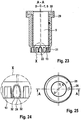
- bearing bush for use together with in Fig. 16 to 20 shown, bearing bush comprises an outer part 29 made of a dimensionally stable plastic, in which an inner part 30 is inserted from a friction-reducing plastic for supporting a hinge pin, not shown in the drawing.
- lower end comprises the bearing bush 4 in further difference from the particular with reference to Fig. 1 and 3 described embodiment, a key surface 13 which is approximately complementary to the counter key surface 14 and thus formed like a ring gear.
- a counter-latching device 22 for the latching device 21 of the lifting spindle 6 is formed in the contour 31 forming the wrench surface 13.
- the counter-latching device 22 comprises two mutually oppositely disposed latching recesses 24, which are formed approximately complementary to the latching projections 23 and thus have a constriction 32, under the elastic extension of the "bulbous" latching projections 23 selectively inserted or removed by displacement of the lifting spindle in the direction of the rotation axis D. are.
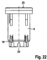
- Fig. 25 is removable - at the according FIGS. 22 to 24 upper end face 25, a first mark 26 is arranged in the form of an outwardly directed arrow.
- This first marking 26 points in a direction perpendicular to the connecting plane between the latching recesses 22, in which also the axis of rotation D and the hinge axis S or longitudinal axis T are offset from each other.
- the current adjustment position can be recognized by a user with the aid of the first marking 26.
- a second mark 27 is provided in the form of two recesses on the support side 9 of the lifting spindle 6.
- the two recesses are arranged opposite to the two locking projections 23, so that they characterize their position and thus the lifting spindle can be brought to place in their function as a rotary tool in the required position for latching.
Description
Die Erfindung betrifft einen Bandlappen eines Bandes zur um eine Scharnierachse scharniergelenkigen Verbindung eines Flügels an einem Rahmen, mit einer Längsausnehmung, mit einer in der Längsausnehmung angeordneten, um eine zur Scharnierachse parallelen, seitlich versetzten Drehachse mittels eines Drehwerkzeugs drehbaren Lagerbuchse, die eine Lagerbuchsenausnehmung zur Aufnahme eines die Scharnierachse definierenden Bandbolzens umfasst, mit einem in Betriebsstellung zumindest im unteren Bereich der Längsausnehmung vorgesehenen Innengewinde, und mit einer ein Außengewinde aufweisenden, in das Innengewinde einschraubbaren Hebespindel, die eine Stützseite zum mittelbaren oder unmittelbaren Abstützen der Lagerbuchse und/oder des Bandbolzens aufweist.The invention relates to a hinge strap of a band hinged to a hinge axis connection of a wing to a frame, with a longitudinal recess, arranged in the longitudinal recess with a hinge axis parallel to the laterally offset axis of rotation by means of a rotary tool rotatable bearing bush having a Lagerbuchsenausnehmung for receiving a hinge pin defining the hinge axis comprises, with a provided in the operating position at least in the lower region of the longitudinal recess internal thread, and having an external thread, screwed into the internal screw lifting spindle having a support side for direct or indirect support of the bearing bush and / or the hinge pin.
Das Dokument
Um die hierzu benötigte Verdrehung der Lagerbuchse zu bewerkstelligen, muss bei dem bekannten Türband zunächst die Hebespindel, auf der sich die Lagerbuchse und/oder der Bandbolzen abstützen, unter Einbußen der Höhenjustierung vollständig herausgedreht werden. An dem dann zugänglichen, bezogen auf die Betriebsstellung unteren Ende der Lagerbuchse, an welchem eine geeignete Schlüsselfläche vorgesehen ist, kann dann ein separat vorzuhaltendes Drehwerkzeug angesetzt werden, um die Lagerbuchse in der Längsausnehmung zu verdrehen, und zwar aus einer Mittelstellung um bis zu +/- 90°.In order to accomplish the required rotation of the bearing bush, in the known door hinge first, the lifting spindle, on which the bearing bush and / or the hinge pin are supported, must be completely unscrewed while sacrificing the height adjustment. At the then accessible, based on the operating position lower end of the bearing bush, on which a suitable key surface is provided, then a separately vorzuhaltendes rotary tool can be used to rotate the bearing bush in the longitudinal recess, and from a center position by up to + / - 90 °.
Nachdem durch diese Verdrehung der gewünschte Dichtungsandruck erreicht ist, erfolgt die erneute Höhenjustierung dadurch, dass die Hebespindel soweit in die Längsausnehmung eingedreht wird, bis der sich an der Lagerbuchse und/oder dem Bandbolzen abstützende, andere Bandlappen die für die korrekte Höhenjustierung des Flügels in dem Rahmen erforderliche Position erreicht hat.After this rotation of the desired sealing pressure is reached, the new height adjustment takes place in that the lifting spindle is screwed as far into the longitudinal recess until the bearing bush and / or the hinge pin supporting, other hinge tabs for the correct height adjustment of the wing in the Frame has reached the required position.
Nachteilig ist bei diesem gattungsgemäßen Band, dass zur Verdrehung der Lagerbuchse in der Längsausnehmung ein separates Drehwerkzeug erforderlich ist.A disadvantage of this generic tape that a separate turning tool is required for rotation of the bearing bush in the longitudinal recess.
Die Dokumente
Der Erfindung liegt daher die Aufgabe zugrunde, einen verbesserten Bandlappen zu schaffen.The invention is therefore based on the object to provide an improved hinge strap.
Diese Aufgabe wird durch den in Anspruch 1 wiedergegebenen Bandlappen gelöst.This object is achieved by the reproduced in claim 1 hinge flap.
Dadurch, dass die Hebespindel selbst als wahlweise ansetzbares Drehhilfsmittel ausgebildet ist, kann auf ein separat vorzuhaltendes Drehwerkzeug verzichtet werden. Die Hebespindel wird also selbst als Drehwerkzeug verwendet. Es ist daher wirksam vermieden, dass eine Dichtungsandruckeinstellung wegen Fehlen eines passenden Drehwerkzeugs unmöglich ist.The fact that the lifting spindle itself is designed as a selectively attachable rotary auxiliary means, can be dispensed with a separately vorzuhaltendes rotary tool. The lifting spindle is therefore used as a turning tool itself. It is therefore effectively avoided that a Dichtungsandruckeinstellung is impossible due to the lack of a suitable turning tool.
Ist die Lagerbuchsenausnehmung derart ausgebildet, dass ihre Längsachse seitlich versetzt zur Drehachse angeordnet ist, kann der Bandbolzen als gerades Bauteil mit über seiner Gesamtlänge konstantem, kreisrunden Querschnitt ausgebildet sein.If the bearing bush recess is formed in such a way that its longitudinal axis is arranged laterally offset from the axis of rotation, the hinge pin can be in the form of a straight component be formed over its entire length constant, circular cross-section.
Um die Hebespindel als wahlweise ansetzbares Drehhilfsmittel verwenden zu können, ist erfindungsgemäß an der Lagerbuchse eine Schlüsselfläche und an der Hebespindel eine mit der Schlüsselfläche in Wirkverbindung bringbare Gegenschlüsselfläche vorgesehen. Ist die Gegenschlüsselfläche an der der Stützseite gegenüberliegenden Seite der Hebespindel angeordnet, so kann die Hebespindel in ihrer Funktion als Drehwerkzeug verwendet werden, indem sie zunächst vollständig aus der Längsausnehmung herausgedreht und umgekehrt, d.h. mit der Stützseite nun von der Lagerbuchse und/oder dem Bandbolzen fort weisend, an die Lagerbuchse angesetzt wird. Befindet sich dabei das Außengewinde der Hebespindel außerhalb der Längsausnehmung, so kann es nun die Handhabe des Drehwerkzeugs bilden.In order to be able to use the lifting spindle as a selectively attachable turning aid, according to the invention a key face is provided on the bearing bush and a counter key face which can be brought into operative connection with the key face is provided on the lifting spindle. If the mating key surface is located on the opposite side of the lifting spindle from the support side, the lifting spindle can be used in their function as a turning tool by first completely unscrewed from the longitudinal recess and vice versa, i. now facing away from the bearing bush and / or the hinge pin with the support side, is attached to the bearing bush. If the external thread of the lifting spindle is outside the longitudinal recess, it can now form the handle of the turning tool.
Besonders bevorzugt ist eine Weiterbildung des erfindungsgemäßen Bandlappens, bei welcher die Längsausnehmung mindestens eine radiale Rastvertiefung aufweist. An der Lagerbuchse ist dann vorzugsweise mindestens ein Rastvorsprung vorgesehen, der mit der Rastvertiefung in Wirkverbindung bringbar ist. Sind lediglich eine einzige Rastvertiefung und ein einziger Rastvorsprung vorgesehen, so sind diese vorzugsweise derart angeordnet, dass sich diese in Mittelstellung in Wirkverbindung befinden, d.h. das Einrasten die Mittelstellung definiert, aus welcher die Lagerbuchse um +/- 90° verdrehbar ist. Vorzugsweise sind jedoch mehrere Rastvertiefungen und Rastvorsprünge vorgesehen, beispielsweise um 90° oder 45° um die Drehachse versetzt angeordnet. Ein Einrasten findet bei einer Drehung der Lagerbuchse in der Längsausnehmung dann alle 90° bzw. alle 45° statt, wodurch genau definierte Positionen der Lagerbuchse leichter auffindbar und einhaltbar sind.Particularly preferred is a development of the hinge flap according to the invention, in which the longitudinal recess has at least one radial detent recess. At the bearing bush then preferably at least one locking projection is provided which can be brought into operative connection with the latching recess. If only a single detent recess and a single detent projection are provided, then these are preferably arranged such that they are in operative connection in the middle position, i. the locking defines the middle position, from which the bearing bush can be rotated by +/- 90 °. Preferably, however, a plurality of locking recesses and locking projections are provided, for example, arranged offset by 90 ° or 45 ° about the axis of rotation. A snap takes place at a rotation of the bearing bush in the longitudinal recess then every 90 ° or every 45 °, whereby exactly defined positions of the bearing bush are easier to find and maintain.
Besonders bevorzugt ist dann eine Weiterbildung des erfindungsgemäßen Bandlappens, bei welcher die Hebespindel derart ausgebildet ist, dass der mindestens eine Rastvorsprung in Wirkverbindung mit der mindestens einen Rastvertiefung arretiert ist, wenn sich die Lagerbuchse und/oder der Bandbolzen in mittelbarer oder unmittelbarer Anlage mit der Stützseite befinden. Hierdurch wird verhindert, dass sich bei einer Verdrehung der Hebespindel zum Zwecke der Höhenjustierung die Lagerbuchse unerwünscht mitdreht, was ansonsten zu einer unerwünschten Veränderung des Dichtungsandrucks führen würde.Particularly preferred is a development of the hinge flap according to the invention, in which the lifting spindle is designed such that the at least one latching projection is locked in operative connection with the at least one latching recess when the bearing bush and / or the hinge bolt in indirectly or immediate contact with the support side. This prevents that during a rotation of the lifting spindle for the purpose of height adjustment, the bearing bush rotates undesirable, which would otherwise lead to an undesirable change in Dichtandrucks.
Um dieses Arretieren zu bewirken, kann die Hebespindel einen die Stützseite umgebenden, ringförmigen Ansatz aufweisen, der den mindestens einen Rastvorsprung hintergreift, wenn sich die Lagerbuchse und/oder der Bandbolzen in mittelbarer oder unmittelbarer Anlage mit der Stützseite befinden.In order to effect this locking, the lifting spindle can have an annular projection surrounding the support side, which engages behind the at least one latching projection when the bearing bush and / or the hinge bolt are in direct or indirect contact with the support side.
An der der Stützseite gegenüberliegenden Seite der Hebespindel kann ein ringförmiger Rand vorgesehen sein, der in eine an der Lagerbuchse vorgesehene oder zwischen der Lagerbuchse und dem Scharnierteil gebildete Ringnut eingreift, wenn sich die Schlüssel- und die Gegenschlüsselflächen in Wirkverbindung befinden. Aufgrund dieser Maßnahme lässt sich der "Sitz" der Hebespindel an der Lagerbuchse, wenn die Hebespindel als Drehhilfsmittel dient, gegen ein unerwünschtes Lösen während des Drehvorganges verbessern.On the support side opposite side of the lifting spindle, an annular rim may be provided which engages in a provided on the bearing bush or formed between the bearing bush and the hinge part annular groove when the key and the counter key surfaces are in operative connection. Due to this measure, the "seat" of the lifting spindle on the bearing bush, when the lifting spindle serves as a rotation aid, can be improved against unwanted loosening during the turning process.
Um das maximale Drehmoment, welches von der als Drehhilfsmittel dienenden Hebespindel auf die Lagerbuchse übertragen werden kann, zu erhöhen, können der Rand und die Lagerbuchse Mittel zum Übertragen von Drehmomenten zwischen dem Rand und der Lagerbuchse umfassen.In order to increase the maximum torque which can be transmitted to the bearing bushing from the lifting spindle serving as a turning aid, the edge and the bearing bushing can comprise means for transmitting torques between the edge and the bearing bush.
Die Mittel können durch mindestens einen an dem Rand vorgesehenen Vorsprung oder mindestens einer an dem Rand vorgesehenen Vertiefung und durch mindestens eine komplementäre Vertiefung oder mindestens einen komplementären Vorsprung der Lagerbuchse in Wirkverbindung befinden, wenn sich die Schlüssel- und Gegenschlüsselflächen in Eingriff befinden.The means may be operatively connected by at least one protrusion provided on the edge or at least one recess provided on the edge and by at least one complementary recess or at least one complementary protrusion of the bearing bush when the key and counter key surfaces are engaged.
Damit die Hebespindel in ihrer Funktion als Drehhilfsmittel sich nicht selbsttätig von der Lagerbuchse lösen kann, sind vorzugsweise auf der Seite der Gegenschlüsselfläche eine Rasteinrichtung und an der Lagerbuchse eine Gegenrasteinrichtung vorgesehen.Thus, the lifting spindle can not automatically solve their function as a rotary tool from the bearing bush, a locking device and on the bearing bush a counter-locking device are preferably provided on the side of the mating key surface.
Die Rasteinrichtung kann ein Rastvorsprung und die Gegenrasteinrichtung eine Rastausnehmung sein, derart, dass die Hebespindel wahlweise unter Überwindung einer Rastkraft auf die Lagerbuchse unter Ineingriffbringen von Schlüsselfläche und Gegenschlüsselfläche aufsetzbar oder unter Trennung von Schlüsselfläche und Gegenschlüsselfläche von der Lagerbuchse abnehmbar ist.The latching device may be a latching projection and the mating latching device may be a latching recess, such that the lifting spindle can be placed under overcoming a latching force on the bearing bushing by engaging the key surface and mating key surface or separating the key surface and mating key surface from the bearing bushing.
Bei einer konstruktiven, bevorzugten Variante erstreckt der Rastvorsprung sich von der Gegenschlüsselfläche radial nach außen.In a constructive, preferred variant, the latching projection extends radially outwards from the counterkey surface.
Die Gegenrastausnehmung kann in der die Schlüsselfläche bildenden Kontur der Lagerbuchse vorgesehen sein.The counter-latching recess can be provided in the contour of the bearing bush forming the key surface.
Besonders bevorzugt ist es, wenn zwei bezüglich der Drehachse um 180° zueinander versetzte Rast- und Gegenrasteinrichtungen vorgesehen sind, da hierdurch eine besonders wirksame Sicherung gegen selbsttätiges Lösen bewirkt wird.It is particularly preferred if two with respect to the axis of rotation by 180 ° staggered latching and counter-locking devices are provided, as this is a particularly effective protection against automatic release is effected.
Um das Aufsetzen der Hebespindel auf die Lagerbuchse in ihrer Funktion als Drehhilfsmittel zu erleichtern, sind die Gegenrasteinrichtungen vorzugsweise in bestimmten Winkelbeziehungen zum seitlichen Versatz der Längsachse und der Drehachse angeordnet. Befindet sich die Lagerbuchse beispielsweise im Auslieferzustand des Bandlappens in einer fest vordefinierten "Nullstellung", so ist für den Anwender zweifelsfrei vorgegeben, in welcher Ausrichtung sich die Gegenrasteinrichtungen befinden. Die Hebespindel in ihrer Funktion als Drehhilfsmittel kann dann gezielt ohne Fehlversuche aufgesetzt werden, selbst wenn aufgrund der Einbausituation das stirnseitige Ende der Lagerbuchse, auf welches die Hebespindel aufgesetzt wird, nicht optisch erfasst werden kann.In order to facilitate the placement of the lifting spindle on the bearing bush in its function as a rotation aid, the counter-locking devices are preferably arranged in certain angular relationships to the lateral offset of the longitudinal axis and the axis of rotation. If, for example, the bearing bushing is in a predefined "zero position" when the band strap is delivered, then the user is unambiguously given the orientation in which the counter-locking devices are located. The lifting spindle in its function as a rotation aid can then be placed specifically without failures, even if due to the installation situation, the front end of the bearing bush on which the lifting spindle is placed, can not be optically detected.
Um die Richtung des seitlichen Versatzes zwischen der Längsachse der Ausnehmung der Lagerbuchse und der Drehachse derselben in dem Bandlappen optisch zweifelsfrei erfassen zu können, ist die Richtung dieses seitlichen Versatzes vorzugsweise auf der von der Schlüsselfläche fortweisenden Stirnfläche der Lagerbuchse durch eine erste Markierung optisch hervorgehoben. Durch Betrachtung des Bandlappens von oben kann somit auf einfache Weise überprüft werden, ob sich die Lagerbuchse beispielsweise in ihrer Nullstellung befindet.In order to detect the direction of the lateral offset between the longitudinal axis of the recess of the bearing bush and the axis of rotation thereof in the hinge strap optically unambiguous, the direction of this lateral offset is preferably on the side facing away from the key surface end face of the bearing bush optically highlighted by a first mark. By looking at the hinge tab from the top can thus be checked in a simple manner, whether the bearing bush, for example, is in its zero position.
Besonders bevorzugt ist darüber hinaus, wenn auf der Stützseite der Hebespindel mindestens eine zweite Markierung vorgesehen ist, die in einer bestimmten Winkelbeziehung zur Rasteinrichtung angeordnet ist. Aufgrund dieser Maßnahme ist das Aufsetzen der Hebespindel in ihrer Funktion als Drehhilfsmittel auf die Lagerbuchse nochmals erleichtert.In addition, it is particularly preferred if at least one second marking is provided on the support side of the lifting spindle, which is arranged in a certain angular relationship to the latching device. Due to this measure, the placement of the lifting spindle is facilitated in its function as a rotary tool on the bearing bush again.
In der Zeichnung sind Ausführungsbeispiele eines erfindungsgemäßen Bandlappens dargestellt. Es zeigen:
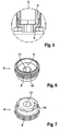
- Fig. 1
- den Bandlappen mit Lagerbuchse und Hebespindel im Längsschnitt, wobei sich die Hebespindel in ihrer eingedrehten Betriebsstellung befindet, in welcher sich die Lagerbuchse auf der Stützseite abstützt;
- Fig. 2
- eine Schnittansicht gemäß
Fig. 1 , jedoch von schräg unten mit separat dargestellter Hebespindel, in der Betriebsposition (oben) und in umgekehrter Position (unten); - Fig. 3
- eine weitere perspektivische Ansicht von schräg unten, wobei jedoch die Lagerbuchse und die Hebespindel nicht geschnitten dargestellt sind, wiederum mit separat dargestellter Hebespindel in Betriebsposition (oben) und umgekehrter Position (unten);
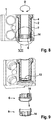
- Fig. 4
- eine
Fig. 2 entsprechende Schnittdarstellung, jedoch in einer perspektivischen Ansicht von schräg oben; - Fig. 5
- den Ausschnitt V in
Fig. 1 ; - Fig. 6
- eine perspektivische Ansicht der Hebespindel in einer bezogen auf ihre eingedrehte Betriebsstellung perspektivische Ansicht von schräg oben;
- Fig. 7
- dieselbe Hebespindel, jedoch um 180° gewendet und strichpunktiert dargestellt;
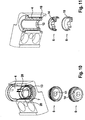
- Fig. 8
- eine
Fig. 1 entsprechende Ansicht, jedoch mit als Drehhilfsmittel dienender Hebespindel; - Fig. 9 bis 14
- Darstellungen, die
Fig. 2 bis 7 entsprechen, wobei jedoch die Hebespindel stets in ihrer Funktion als Drehhilfsmittel dargestellt ist; - Fig. 15
- ein anderes Ausführungsbeispiel der Hebespindel in einer
Fig. 13 entsprechenden Darstellung; - Fig. 16
- ein weiteres Ausführungsbeispiel der Hebespindel in einer
Fig. 15 entsprechenden Darstellung; - Fig. 17
- dasselbe Ausführungsbeispiel der Hebespindel wie in
Fig. 16 , jedoch in einerFig. 6 entsprechenden Darstellung; - Fig. 18
- dasselbe Ausführungsbeispiel der Hebespindel in umgekehrter Position (in ihrer Funktion als Drehhilfsmittel) in einer seitlichen Ansicht;
- Fig. 19
- den Schnitt A-A in
Fig. 18 ; - Fig. 20
- dasselbe Ausführungsbeispiel der Hebespindel in einer Ansicht gemäß
Fig. 18 von oben; - Fig. 21
- den Schnitt B-B in
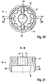
Fig. 20 ; - Fig. 22
- ein weiteres Ausführungsbeispiel einer Lagerbuchse, die zum Zusammenwirken mit dem Ausführungsbeispiel der Hebespindel gemäß
Fig. 16 vorgesehen ist, in einer Seitenansicht;bis 21 - Fig. 23
- einen Längsschnitt (Schnitt A-A gemäß
Fig. 25 ) durch die Lagerbuchse gemäßFig. 22 ; - Fig. 24
- den Ausschnitt X in
Fig. 23 in einer vergrößerten Darstellung sowie - Fig. 25
- die Ansicht der Lagerbuchse gemäß
Fig. 22 von oben.
- Fig. 1
- the hinge plate with bearing bush and lifting spindle in longitudinal section, wherein the lifting spindle is in its screwed operating position, in which the bearing bush is supported on the support side;
- Fig. 2
- a sectional view according to
Fig. 1 but obliquely from below with separately shown lifting spindle, in the operating position (top) and in the reverse position (bottom); - Fig. 3
- a further perspective view obliquely from below, but with the bearing bush and the lifting spindle are not shown in section, again with separately shown lifting spindle in the operating position (top) and reverse position (bottom);
- Fig. 4
- a
Fig. 2 corresponding sectional view, but in a perspective view obliquely from above; - Fig. 5
- the section V in
Fig. 1 ; - Fig. 6
- a perspective view of the lifting spindle in a relation to its screwed operating position perspective view obliquely from above;
- Fig. 7
- the same lifting spindle, but turned by 180 ° and shown in phantom;
- Fig. 8
- a
Fig. 1 corresponding view, but with serving as a rotation aid lifting spindle; - Fig. 9 to 14
- Representations that
Fig. 2 to 7 However, the lifting spindle is always shown in its function as a turning tool; - Fig. 15
- another embodiment of the lifting spindle in one
Fig. 13 corresponding representation; - Fig. 16
- Another embodiment of the lifting spindle in one
Fig. 15 corresponding representation; - Fig. 17
- the same embodiment of the lifting spindle as in
Fig. 16 but in oneFig. 6 corresponding representation; - Fig. 18
- the same embodiment of the lifting spindle in the reverse position (in its function as a rotation aid) in a side view;
- Fig. 19
- the cut AA in
Fig. 18 ; - Fig. 20
- the same embodiment of the lifting spindle in a view according to
Fig. 18 from above; - Fig. 21
- the cut BB in
Fig. 20 ; - Fig. 22
- a further embodiment of a bearing bush, which cooperates with the embodiment of the lifting spindle according to
Fig. 16 to 21 is provided, in a side view; - Fig. 23
- a longitudinal section (section AA according to
Fig. 25 ) through the bearing bush according toFig. 22 ; - Fig. 24
- the section X in
Fig. 23 in an enlarged view as well - Fig. 25
- the view of the bearing bush according to
Fig. 22 from above.
Das in der Zeichnung dargestellte Ausführungsbeispiel eines erfindungsgemäßen Bandlappens 100 ist Teil eines Bandes zur um eine Scharnierachse S scharniergelenkigen Verbindung eines nicht dargestellten Flügels an einem Rahmen. Der Bandlappen 100 ist als Rahmenbandlappen dargestellt.The exemplary embodiment of a
Er umfasst ein Befestigungsteil 1, welches der Befestigung - bei dem dargestellten Ausführungsbeispiel am Rahmen - dient. An das Befestigungsteil 1 ist ein Scharnierteil 2 angeformt. Das Scharnierteil 2 umfasst eine Längsausnehmung 3, in welcher eine Lagerbuchse 4 vorgesehen ist. Letztere ist um eine zur Scharnierachse S parallele, jedoch seitlich versetzte Drehachse D mit Hilfe eines noch im Einzelnen zu beschreibenden Drehhilfsmittels drehbar angeordnet.It comprises a fastening part 1, which is the attachment - in the illustrated embodiment on the frame - is used. On the fastening part 1, a hinge part 2 is formed. The hinge part 2 comprises a longitudinal recess 3, in which a
Die Lagerbuchse 4 weist eine Lagerbuchsenausnehmung 5 mit einer Längsachse T auf, die zur Drehachse D seitlich versetzt ist und bei dem dargestellten Ausführungsbeispiel mit der Scharnierachse S zusammenfällt. Die Lagerbuchsenausnehmung 5 ist mit anderen Worten zentrisch bezüglich des wirksamen Außenumfangs der Lagerbuchse 4 angeordnet. Mit "wirksamer Außenumfang" ist der Außenumfang bezeichnet, der die Drehachse D der Lagerbuchse 4 in der Längsausnehmung 3 definiert.The bearing
In der Längsausnehmung 3 ist ein Innengewinde 7 vorgesehen. In dieses Innengewinde 7 ist - bezogen auf die Betriebsstellung des Bandlappens - von unten eine Hebespindel 6, die ein zum Innengewinde 7 komplementäres Außengewinde 8 aufweist, eingedreht. Die Hebespindel 6 weist auf ihrer in der in
Wie aus
Wie bereits weiter oben erwähnt, ist die Lagerbuchsenausnehmung 5 exzentrisch zum wirksamen Außenumfang der Lagerbuchse 4 angeordnet. Wird die Lagerbuchse 4 innerhalb der Längsausnehmung 3 gedreht, so verlagert sich die Längsachse T und damit die Scharnierachse S relativ zum Scharnierteil 2. Hierdurch wird der in der Zeichnung nicht dargestellte andere Bandlappen - hier der Flügelbandlappen - relativ zum Bandlappen 100 senkrecht zur Drehachse D verlagert, wodurch beispielsweise eine Dichtungsandruckänderung erzielbar ist.As already mentioned above, the bearing
Um die Drehung der Lagerbuchse 4 in der Längsausnehmung 3 - wie durch Pfeil O symbolisiert - bewirken zu können, sind an dem unteren Endbereich der Lagerbuchse 4 eine als Innensechskant ausgebildete Schlüsselfläche 13 und an der der Stützseite 9 gegenüberliegenden Seite der Hebespindel 6 eine als komplementärer Außensechskant ausgebildete Gegenschlüsselfläche 14 vorgesehen. Die Drehbetätigung der Lagerbuchse 4 kann daher erfolgen, indem die Hebespindel 6 zunächst aus ihrer in
Um in dieser "Drehbetätigungsstellung" den Sitz der Hebespindel 6 an der Lagerbuchse 4 zu verbessern, ist ein die Gegenschlüsselfläche 14 umgebender Rand 15 vorgesehen, welcher in eine an der Lagerbuchse 4 vorgesehene Ringnut 16 eingreift.In order to improve the seat of the lifting
Wie insbesondere in
Die Rastvorsprünge 18 sind derart ausgelegt, dass sie von dem ringförmigen Ansatz 10 der Hebespindel 6 hintergriffen werden, wenn diese in ihrer Betriebsposition, in welcher sich die Lagerbuchse 4 an der Stützseite 9 abstützt, in das Innengewinde 7 eingeschraubt ist. Aufgrund dieser Maßnahme wird zuverlässig verhindert, dass sich die Lagerbuchse 4 innerhalb der Längsausnehmung 3 mitdrehen kann, wenn aufgrund eines Reibschlusses durch Abstützen auf der Stützseite 9 von der Hebespindel 6 ein Drehmoment auf die Lagerbuchse 4 während eines Höhenjustiervorganges in Richtung P ausgeübt wird.The latching
Ein weiteres Ausführungsbeispiel einer Hebespindel 6 ist in den
Wie insbesondere in
Schließlich sind an dem Außengewinde 8 der Hebespindel in einer gegenüberliegend und bezüglich der Rastvorsprünge 23 um die Drehachse D um 90° versetzt zwei ebene Flächen 28 zum Ansetzen eines in der Zeichnung nicht dargestellten Drehwerkzeugs zum Verdrehen der Hebespindel 6 in ihrer Funktion als Drehhilfsmittel vorgesehen.Finally, on the
Die in
An dem gemäß
Die Gegenrasteinrichtung 22 umfasst zwei einander gegenüberliegend angeordnete Rastausnehmungen 24, die etwa komplementär zu den Rastvorsprüngen 23 ausgebildet sind und damit eine Engstelle 32 aufweisen, unter deren elastischer Erweiterung die "bauchigen" Rastvorsprünge 23 wahlweise durch Verlagerung der Hebespindel in Richtung der Drehachse D einführbar oder entnehmbar sind.The counter-latching device 22 comprises two mutually oppositely disposed latching recesses 24, which are formed approximately complementary to the latching
Um das Auffinden der korrekten Drehstellungen bezüglich der Drehachse D zum Aufsetzen der Hebespindel 6 in ihrer Funktion als Drehhilfsmittel zu erleichtern, ist - wie
Wie in
- 100100
- Bandlappenhinge flap
- 11
- Befestigungsteilattachment portion
- 22
- Scharnierteilhinge part
- 33
- Längsausnehmunglongitudinal recess
- 44
- Lagerbuchsebearing bush
- 55
- LagerbuchsenausnehmungLagerbuchsenausnehmung
- 66
- Hebespindellifting spindle
- 77
- Innengewindeinner thread
- 88th
- Außengewindeexternal thread
- 99
- Stützseitesupport page
- 1010
- ringförmiger Ansatzannular approach
- 1111
- InnensechskantAllen
- 1212
- Drehhilfsmittelrotary tools
- 1313
- Schlüsselflächekey area
- 1414
- GegenschlüsselflächeAgainst key area
- 1515
- Randedge
- 1616
- Ringnutring groove
- 1717
- Rastvertiefungenlocking recesses
- 1818
- Rastvorsprüngelatching projections
- 1919
- Vorsprunghead Start
- 2020
- Vertiefungdeepening
- 2121
- Rasteinrichtunglocking device
- 2222
- GegenrasteinrichtungAgainst latching device
- 2323
- Rastvorsprungcatch projection
- 2424
- Rastausnehmungrecess
- 2525
- Stirnseitefront
- 2626
- erste Markierungfirst mark
- 2727
- zweite Markierungsecond mark
- 2828
- ebene Flächeflat surface
- 2929
- äußerer Teilouter part
- 3030
- innerer Teilinner part
- 3131
- Konturcontour
- 3232
- Engstellebottleneck
- DD
- Drehachseaxis of rotation
- OO
- Pfeilarrow
- PP
- Richtungdirection
- SS
- Scharnierachsehinge axis
- TT
- Längsachselongitudinal axis
- VV
- Einzelheitdetail
- XIIXII
- Einzelheitdetail
Claims (15)
- A hinge strap (100) of a hinge for an articulated connection, which is hinged around a hinge axis (S), between a door leaf and a frame,
having a longitudinal recess (3),
having a bushing (4) arranged in the longitudinal recess (3) that is rotatable by means of a rotary tool about a rotational axis (D) that is parallel to and laterally offset from the hinge axis (S), the bushing comprising a bushing recess (5) for receiving a hinge bolt, with an inner thread (7) which, in the operational position, is provided at least in the lower region of the longitudinal recess (3),
and with a lifting spindle (6) featuring an outer thread (8) that can be screwed into the inner thread (7), featuring a support side (9) for indirectly or directly supporting the bushing (4) and/or the hinge bolt,
characterized in that
a key surface (13) is provided on the bushing (4), and a counter-key surface (14) that may be brought into engagement with the key surface (13) is provided on the lifting spindle (6), the counter-key surface being arranged on the side of the lifting spindle (6) opposite the support side (9), so that the lifting spindle (6) is designed as an optionally applicable auxiliary rotary means (12) that may be used in its function as rotary tool in that it is initially screwed out completely from the longitudinal recess and then applied inversely to the bushing (4) with the support side (9) pointing away from the bushing (4) and/or the hinge bolt. - Hinge strap according to claim 1, characterized in that the bushing recess (5) has a longitudinal axis (T) that is laterally offset from the rotational axis (D).
- Hinge strap according to claim 1 or 2, characterized in that the longitudinal recess (3) has at least one radial detent depression (17) and that at least one detent protrusion (18) is provided on the bushing (4).
- Hinge strap according to claim 3, characterized in that the lifting spindle (6) is designed in such a way that the at least one detent protrusion (18) may be brought into engagement with the at least one detent depression (17) and locked, when the bushing (4) and/or the hinge bolt are indirectly or directly abutting the support side (9).
- Hinge strap according to claim 4, characterized in that the lifting spindle (6) has an annular lug (10) surrounding the support side (9), which engages the at least one detent protrusion (18) when the bushing (4) and/or the hinge bolt are indirectly or directly abutting the support side (9).
- Hinge strap according to any of claims 1 to 5, characterized in that an annular edge (15) is provided on the side of the lifting spindle (6) opposite the support side (9), engaging an annular groove (16) provided on the bushing (4) or formed between the bushing (4) and the hinge part (2) when the key surface and counter-key surface (13, 14) are operatively connected.
- Hinge strap according to claim 6, characterized in that the edge (15) and the bushing (4) comprise means for transmitting torque between the edge (15) and the bushing (4).
- Hinge strap according to claim 7, characterized in that at least one protrusion (19) or at least one depression is provided on the edge (15), operatively connected to at least one complementary depression (20) or at least one complementary protrusion or to the bushing (4) when the key surface and the counter-key surface (13, 14) are mutually engaged.
- Hinge strap according to any of claims 1 to 8, characterized in that a detent device (21) is provided on the side of the counter-key surface (14) and a counter-detent device (22) is provided on the bushing (4), wherein, preferably, the detent device (21) is a detent protrusion (23) and the counter-detent device is a detent recess (24), so that the lifting spindle (6) may be selectively applied, by overcoming a detent force, on the bushing (4), by bringing the key surface (13) and the counter-key surface (14) into engagement, or may be removed from the bushing (4) by separating the key surface (13) from the counter-key surface (14).
- Hinge strap according to claim 9, characterized in that the detent protrusion (23) radially and outwardly extends from the counter-key surface (14).
- Hinge strap according to claim 9 or 10, characterized in that the counter-detent recess is provided in the profile of the bushing (4) which forms the key surface (13).
- Hinge strap according to any of claims 9 to 11, characterized in that two detent and counter-detent devices are provided, which are mutually offset by 180° relative to the rotational axis.
- Hinge strap according to any of claims 9 to 12, characterized in that the counter-detent devices (22) are positioned with specific angular relationships to the lateral offset of the longitudinal axis (T) and the rotational axis (D).
- Hinge strap according to claim 13, characterized in that the direction of the lateral offset on the front side (25) of the bushing (4) facing away from the key surface (13) is optically emphasized by a first marking (26).
- Hinge strap according to claim 14, characterized in that at least one second marking (27) is provided on the support side (9) of the lifting spindle (6), wherein the marking is positioned in a specific angular relationship with respect to the detent device (23).
Priority Applications (1)
| Application Number | Priority Date | Filing Date | Title |
|---|---|---|---|
| PL14711503T PL3019683T3 (en) | 2013-07-12 | 2014-03-19 | Strap of a hinge |
Applications Claiming Priority (2)
| Application Number | Priority Date | Filing Date | Title |
|---|---|---|---|
| DE202013103109.7U DE202013103109U1 (en) | 2013-07-12 | 2013-07-12 | Band lobe of a band |
| PCT/EP2014/055464 WO2015003822A1 (en) | 2013-07-12 | 2014-03-19 | Strap of a hinge |
Publications (2)
| Publication Number | Publication Date |
|---|---|
| EP3019683A1 EP3019683A1 (en) | 2016-05-18 |
| EP3019683B1 true EP3019683B1 (en) | 2018-12-12 |
Family
ID=50342314
Family Applications (1)
| Application Number | Title | Priority Date | Filing Date |
|---|---|---|---|
| EP14711503.4A Active EP3019683B1 (en) | 2013-07-12 | 2014-03-19 | Strap of a hinge |
Country Status (7)
| Country | Link |
|---|---|
| EP (1) | EP3019683B1 (en) |
| CN (1) | CN105452585B (en) |
| DE (1) | DE202013103109U1 (en) |
| PL (1) | PL3019683T3 (en) |
| RU (1) | RU2638626C2 (en) |
| TR (1) | TR201900139T4 (en) |
| WO (1) | WO2015003822A1 (en) |
Families Citing this family (2)
| Publication number | Priority date | Publication date | Assignee | Title |
|---|---|---|---|---|
| DE102018100774B3 (en) * | 2018-01-15 | 2018-09-27 | Dr. Hahn Gmbh & Co. Kg | Band lobe of a band |
| DE102020109532B3 (en) * | 2020-04-06 | 2021-02-11 | Dr. Hahn Gmbh & Co. Kg | Tape for a hinge-joint connection around a hinge axis |
Family Cites Families (13)
| Publication number | Priority date | Publication date | Assignee | Title |
|---|---|---|---|---|
| US3999246A (en) * | 1974-09-24 | 1976-12-28 | The Stanley Works | Two knuckle hinges |
| DE29703324U1 (en) * | 1997-02-25 | 1998-07-02 | Hahn Gmbh & Co Kg Dr | Tape for doors, windows and the like |
| IT1308737B1 (en) * | 1999-06-16 | 2002-01-10 | Savio Spa | HINGE FOR OPENABLE FRAMES |
| PT1455042E (en) * | 2003-02-21 | 2007-10-29 | Master Srl | Adjustable hinge for window or door casing |
| DE202004011539U1 (en) * | 2004-07-22 | 2005-12-08 | Dr. Hahn Gmbh & Co. Kg | Tape for doors, windows and the like |
| ES2333552T3 (en) * | 2007-08-09 | 2010-02-23 | Roto Frank Aktiengesellschaft | HINGE HARDWARE FOR A WINDOW, A DOOR OR SIMILAR, WITH AN OBLIQUE CAP. |
| CN201170011Y (en) * | 2007-11-22 | 2008-12-24 | 李英学 | Flexible type hinge |
| DE202008014318U1 (en) * | 2008-10-28 | 2010-04-01 | Dr. Hahn Gmbh & Co. Kg | Band to hinged about a hinge axis connecting a wing to a frame |
| EP2194218B1 (en) * | 2008-12-05 | 2011-08-31 | SAVIO S.p.A. | A hinge for doors, windows or the like |
| IT1396871B1 (en) * | 2009-12-24 | 2012-12-20 | Gsg Int Spa | HINGE FOR HEAVY DUSTS |
| PL65336Y1 (en) * | 2009-12-28 | 2011-03-31 | Wala Społka Z Ograniczoną Odpowiedzialnością | Hinge, preferably for doors |
| RU2013120281A (en) * | 2010-10-04 | 2014-11-20 | Др. Хан Гмбх Унд Ко. Кг | METHOD AND DEVICE FOR TRANSMISSION OF SIGNALS BETWEEN A WALL AND A CASING, ATTACHED TO THIS WALL WITH HINGE HINGES WITH THE POSSIBILITY OF TURNING AROUND A HINGE AXLE |
| DE202011052372U1 (en) * | 2011-12-20 | 2013-03-21 | Dr. Hahn Gmbh & Co. Kg | Band for the pivotable connection of a wing to a frame |
-
2013
- 2013-07-12 DE DE202013103109.7U patent/DE202013103109U1/en not_active Expired - Lifetime
-
2014
- 2014-03-19 WO PCT/EP2014/055464 patent/WO2015003822A1/en active Application Filing
- 2014-03-19 TR TR2019/00139T patent/TR201900139T4/en unknown
- 2014-03-19 RU RU2016103922A patent/RU2638626C2/en active
- 2014-03-19 EP EP14711503.4A patent/EP3019683B1/en active Active
- 2014-03-19 PL PL14711503T patent/PL3019683T3/en unknown
- 2014-03-19 CN CN201480039667.0A patent/CN105452585B/en active Active
Non-Patent Citations (1)
| Title |
|---|
| None * |
Also Published As
| Publication number | Publication date |
|---|---|
| DE202013103109U1 (en) | 2014-10-13 |
| WO2015003822A1 (en) | 2015-01-15 |
| RU2638626C2 (en) | 2017-12-14 |
| CN105452585B (en) | 2017-05-10 |
| TR201900139T4 (en) | 2019-02-21 |
| CN105452585A (en) | 2016-03-30 |
| PL3019683T3 (en) | 2019-07-31 |
| EP3019683A1 (en) | 2016-05-18 |
| RU2016103922A (en) | 2017-08-17 |
Similar Documents
| Publication | Publication Date | Title |
|---|---|---|
| EP2318723B1 (en) | Fastening arrangement with tolerance compensation | |
| EP2715201B1 (en) | Combination of a plastic hose for laboratory equipments and of a threaded element | |
| EP3384167B1 (en) | Adjustable spacer sleeve | |
| EP1961976B1 (en) | Fastening device | |
| EP2063136B1 (en) | Fastening element with attachable captive washer sleeve | |
| DE60133441T2 (en) | Threaded fasteners | |
| EP1153186B1 (en) | Closure for connecting two thin walls | |
| DE19647742A1 (en) | Device tightening device for captive screws | |
| DE102007039208A1 (en) | Double roller with two wheels and roller with one impeller | |
| EP3612740B1 (en) | Adjustment unit and adjustment method for a component | |
| EP0362883A1 (en) | Box hinge | |
| EP2742199A1 (en) | Fastening assembly for fastening a component to a groove of a window, a door, or the like | |
| EP2209959B1 (en) | Compression closure | |
| EP3425155B1 (en) | Finger guard for a door | |
| EP3019683B1 (en) | Strap of a hinge | |
| WO2019192654A1 (en) | Electrical plug-in connector part and electrical plug-in connection system with locking | |
| EP1527660B1 (en) | Torsional fixing device, especially for the housing of a measuring transducer | |
| EP0939186B1 (en) | Hinge for doors, windows and the like | |
| EP2565351B1 (en) | Handle assembly | |
| DE102006033995A1 (en) | Hub cover for wheel bearing, comprises multiple secured areas, of rotary protection, distributed over periphery of hub cover, where secured areas are subdivided, in peripheral direction, into successive segments with radial extension | |
| DE19803372C2 (en) | Device and method for the assembly of locking devices | |
| DE102012020909B3 (en) | Arrangement for torque adjustment for screwdriver, has coupling element that is arranged in multi-edge retainer of position knob and is provided with multi-edge connecting rod which is inserted in multi-edge opening of press element | |
| EP3062958B1 (en) | Power clamping nut | |
| EP2750269A1 (en) | Pump power unit | |
| EP0467122A1 (en) | Sleeve for pins of hinge fittings |
Legal Events
| Date | Code | Title | Description |
|---|---|---|---|
| PUAI | Public reference made under article 153(3) epc to a published international application that has entered the european phase |
Free format text: ORIGINAL CODE: 0009012 |
|
| 17P | Request for examination filed |
Effective date: 20160212 |
|
| AK | Designated contracting states |
Kind code of ref document: A1 Designated state(s): AL AT BE BG CH CY CZ DE DK EE ES FI FR GB GR HR HU IE IS IT LI LT LU LV MC MK MT NL NO PL PT RO RS SE SI SK SM TR |
|
| AX | Request for extension of the european patent |
Extension state: BA ME |
|
| DAX | Request for extension of the european patent (deleted) | ||
| GRAJ | Information related to disapproval of communication of intention to grant by the applicant or resumption of examination proceedings by the epo deleted |
Free format text: ORIGINAL CODE: EPIDOSDIGR1 |
|
| STAA | Information on the status of an ep patent application or granted ep patent |
Free format text: STATUS: GRANT OF PATENT IS INTENDED |
|
| GRAP | Despatch of communication of intention to grant a patent |
Free format text: ORIGINAL CODE: EPIDOSNIGR1 |
|
| INTG | Intention to grant announced |
Effective date: 20180905 |
|
| GRAS | Grant fee paid |
Free format text: ORIGINAL CODE: EPIDOSNIGR3 |
|
| GRAA | (expected) grant |
Free format text: ORIGINAL CODE: 0009210 |
|
| STAA | Information on the status of an ep patent application or granted ep patent |
Free format text: STATUS: THE PATENT HAS BEEN GRANTED |
|
| AK | Designated contracting states |
Kind code of ref document: B1 Designated state(s): AL AT BE BG CH CY CZ DE DK EE ES FI FR GB GR HR HU IE IS IT LI LT LU LV MC MK MT NL NO PL PT RO RS SE SI SK SM TR |
|
| REG | Reference to a national code |
Ref country code: GB Ref legal event code: FG4D Free format text: NOT ENGLISH |
|
| REG | Reference to a national code |
Ref country code: CH Ref legal event code: EP |
|
| REG | Reference to a national code |
Ref country code: AT Ref legal event code: REF Ref document number: 1076192 Country of ref document: AT Kind code of ref document: T Effective date: 20181215 |
|
| REG | Reference to a national code |
Ref country code: DE Ref legal event code: R096 Ref document number: 502014010314 Country of ref document: DE |
|
| REG | Reference to a national code |
Ref country code: IE Ref legal event code: FG4D Free format text: LANGUAGE OF EP DOCUMENT: GERMAN |
|
| REG | Reference to a national code |
Ref country code: SE Ref legal event code: TRGR |
|
| REG | Reference to a national code |
Ref country code: NL Ref legal event code: FP |
|
| REG | Reference to a national code |
Ref country code: LT Ref legal event code: MG4D |
|
| PG25 | Lapsed in a contracting state [announced via postgrant information from national office to epo] |
Ref country code: FI Free format text: LAPSE BECAUSE OF FAILURE TO SUBMIT A TRANSLATION OF THE DESCRIPTION OR TO PAY THE FEE WITHIN THE PRESCRIBED TIME-LIMIT Effective date: 20181212 Ref country code: BG Free format text: LAPSE BECAUSE OF FAILURE TO SUBMIT A TRANSLATION OF THE DESCRIPTION OR TO PAY THE FEE WITHIN THE PRESCRIBED TIME-LIMIT Effective date: 20190312 Ref country code: LT Free format text: LAPSE BECAUSE OF FAILURE TO SUBMIT A TRANSLATION OF THE DESCRIPTION OR TO PAY THE FEE WITHIN THE PRESCRIBED TIME-LIMIT Effective date: 20181212 Ref country code: NO Free format text: LAPSE BECAUSE OF FAILURE TO SUBMIT A TRANSLATION OF THE DESCRIPTION OR TO PAY THE FEE WITHIN THE PRESCRIBED TIME-LIMIT Effective date: 20190312 Ref country code: ES Free format text: LAPSE BECAUSE OF FAILURE TO SUBMIT A TRANSLATION OF THE DESCRIPTION OR TO PAY THE FEE WITHIN THE PRESCRIBED TIME-LIMIT Effective date: 20181212 Ref country code: HR Free format text: LAPSE BECAUSE OF FAILURE TO SUBMIT A TRANSLATION OF THE DESCRIPTION OR TO PAY THE FEE WITHIN THE PRESCRIBED TIME-LIMIT Effective date: 20181212 Ref country code: LV Free format text: LAPSE BECAUSE OF FAILURE TO SUBMIT A TRANSLATION OF THE DESCRIPTION OR TO PAY THE FEE WITHIN THE PRESCRIBED TIME-LIMIT Effective date: 20181212 |
|
| PG25 | Lapsed in a contracting state [announced via postgrant information from national office to epo] |
Ref country code: AL Free format text: LAPSE BECAUSE OF FAILURE TO SUBMIT A TRANSLATION OF THE DESCRIPTION OR TO PAY THE FEE WITHIN THE PRESCRIBED TIME-LIMIT Effective date: 20181212 Ref country code: RS Free format text: LAPSE BECAUSE OF FAILURE TO SUBMIT A TRANSLATION OF THE DESCRIPTION OR TO PAY THE FEE WITHIN THE PRESCRIBED TIME-LIMIT Effective date: 20181212 Ref country code: GR Free format text: LAPSE BECAUSE OF FAILURE TO SUBMIT A TRANSLATION OF THE DESCRIPTION OR TO PAY THE FEE WITHIN THE PRESCRIBED TIME-LIMIT Effective date: 20190313 |
|
| PG25 | Lapsed in a contracting state [announced via postgrant information from national office to epo] |
Ref country code: PT Free format text: LAPSE BECAUSE OF FAILURE TO SUBMIT A TRANSLATION OF THE DESCRIPTION OR TO PAY THE FEE WITHIN THE PRESCRIBED TIME-LIMIT Effective date: 20190412 |
|
| PG25 | Lapsed in a contracting state [announced via postgrant information from national office to epo] |
Ref country code: EE Free format text: LAPSE BECAUSE OF FAILURE TO SUBMIT A TRANSLATION OF THE DESCRIPTION OR TO PAY THE FEE WITHIN THE PRESCRIBED TIME-LIMIT Effective date: 20181212 Ref country code: SM Free format text: LAPSE BECAUSE OF FAILURE TO SUBMIT A TRANSLATION OF THE DESCRIPTION OR TO PAY THE FEE WITHIN THE PRESCRIBED TIME-LIMIT Effective date: 20181212 Ref country code: IS Free format text: LAPSE BECAUSE OF FAILURE TO SUBMIT A TRANSLATION OF THE DESCRIPTION OR TO PAY THE FEE WITHIN THE PRESCRIBED TIME-LIMIT Effective date: 20190412 Ref country code: RO Free format text: LAPSE BECAUSE OF FAILURE TO SUBMIT A TRANSLATION OF THE DESCRIPTION OR TO PAY THE FEE WITHIN THE PRESCRIBED TIME-LIMIT Effective date: 20181212 Ref country code: SK Free format text: LAPSE BECAUSE OF FAILURE TO SUBMIT A TRANSLATION OF THE DESCRIPTION OR TO PAY THE FEE WITHIN THE PRESCRIBED TIME-LIMIT Effective date: 20181212 |
|
| REG | Reference to a national code |
Ref country code: DE Ref legal event code: R097 Ref document number: 502014010314 Country of ref document: DE |
|
| PLBE | No opposition filed within time limit |
Free format text: ORIGINAL CODE: 0009261 |
|
| STAA | Information on the status of an ep patent application or granted ep patent |
Free format text: STATUS: NO OPPOSITION FILED WITHIN TIME LIMIT |
|
| PG25 | Lapsed in a contracting state [announced via postgrant information from national office to epo] |
Ref country code: DK Free format text: LAPSE BECAUSE OF FAILURE TO SUBMIT A TRANSLATION OF THE DESCRIPTION OR TO PAY THE FEE WITHIN THE PRESCRIBED TIME-LIMIT Effective date: 20181212 Ref country code: SI Free format text: LAPSE BECAUSE OF FAILURE TO SUBMIT A TRANSLATION OF THE DESCRIPTION OR TO PAY THE FEE WITHIN THE PRESCRIBED TIME-LIMIT Effective date: 20181212 Ref country code: MC Free format text: LAPSE BECAUSE OF FAILURE TO SUBMIT A TRANSLATION OF THE DESCRIPTION OR TO PAY THE FEE WITHIN THE PRESCRIBED TIME-LIMIT Effective date: 20181212 |
|
| REG | Reference to a national code |
Ref country code: CH Ref legal event code: PL |
|
| 26N | No opposition filed |
Effective date: 20190913 |
|
| PG25 | Lapsed in a contracting state [announced via postgrant information from national office to epo] |
Ref country code: LU Free format text: LAPSE BECAUSE OF NON-PAYMENT OF DUE FEES Effective date: 20190319 |
|
| PG25 | Lapsed in a contracting state [announced via postgrant information from national office to epo] |
Ref country code: IE Free format text: LAPSE BECAUSE OF NON-PAYMENT OF DUE FEES Effective date: 20190319 Ref country code: LI Free format text: LAPSE BECAUSE OF NON-PAYMENT OF DUE FEES Effective date: 20190331 Ref country code: CH Free format text: LAPSE BECAUSE OF NON-PAYMENT OF DUE FEES Effective date: 20190331 |
|
| PG25 | Lapsed in a contracting state [announced via postgrant information from national office to epo] |
Ref country code: MT Free format text: LAPSE BECAUSE OF FAILURE TO SUBMIT A TRANSLATION OF THE DESCRIPTION OR TO PAY THE FEE WITHIN THE PRESCRIBED TIME-LIMIT Effective date: 20181212 |
|
| PG25 | Lapsed in a contracting state [announced via postgrant information from national office to epo] |
Ref country code: CY Free format text: LAPSE BECAUSE OF FAILURE TO SUBMIT A TRANSLATION OF THE DESCRIPTION OR TO PAY THE FEE WITHIN THE PRESCRIBED TIME-LIMIT Effective date: 20181212 |
|
| PGFP | Annual fee paid to national office [announced via postgrant information from national office to epo] |
Ref country code: GB Payment date: 20210310 Year of fee payment: 8 Ref country code: AT Payment date: 20210225 Year of fee payment: 8 |
|
| PG25 | Lapsed in a contracting state [announced via postgrant information from national office to epo] |
Ref country code: HU Free format text: LAPSE BECAUSE OF FAILURE TO SUBMIT A TRANSLATION OF THE DESCRIPTION OR TO PAY THE FEE WITHIN THE PRESCRIBED TIME-LIMIT; INVALID AB INITIO Effective date: 20140319 |
|
| PG25 | Lapsed in a contracting state [announced via postgrant information from national office to epo] |
Ref country code: MK Free format text: LAPSE BECAUSE OF FAILURE TO SUBMIT A TRANSLATION OF THE DESCRIPTION OR TO PAY THE FEE WITHIN THE PRESCRIBED TIME-LIMIT Effective date: 20181212 |
|
| REG | Reference to a national code |
Ref country code: AT Ref legal event code: MM01 Ref document number: 1076192 Country of ref document: AT Kind code of ref document: T Effective date: 20220319 |
|
| GBPC | Gb: european patent ceased through non-payment of renewal fee |
Effective date: 20220319 |
|
| REG | Reference to a national code |
Ref country code: DE Ref legal event code: R082 Ref document number: 502014010314 Country of ref document: DE Representative=s name: PATENTANWAELTE KLUIN DEBELIUS WEBER PARTG MBB, DE |
|
| PG25 | Lapsed in a contracting state [announced via postgrant information from national office to epo] |
Ref country code: GB Free format text: LAPSE BECAUSE OF NON-PAYMENT OF DUE FEES Effective date: 20220319 Ref country code: AT Free format text: LAPSE BECAUSE OF NON-PAYMENT OF DUE FEES Effective date: 20220319 |
|
| PGFP | Annual fee paid to national office [announced via postgrant information from national office to epo] |
Ref country code: FR Payment date: 20230309 Year of fee payment: 10 Ref country code: CZ Payment date: 20230313 Year of fee payment: 10 |
|
| PGFP | Annual fee paid to national office [announced via postgrant information from national office to epo] |
Ref country code: TR Payment date: 20230227 Year of fee payment: 10 Ref country code: SE Payment date: 20230227 Year of fee payment: 10 Ref country code: PL Payment date: 20230228 Year of fee payment: 10 Ref country code: IT Payment date: 20230228 Year of fee payment: 10 Ref country code: DE Payment date: 20230331 Year of fee payment: 10 Ref country code: BE Payment date: 20230315 Year of fee payment: 10 |
|
| P01 | Opt-out of the competence of the unified patent court (upc) registered |
Effective date: 20230523 |
|
| PGFP | Annual fee paid to national office [announced via postgrant information from national office to epo] |
Ref country code: NL Payment date: 20230314 Year of fee payment: 10 |