EP3018754B1 - Appareil de détection d'état de batterie et son procédé de fabrication - Google Patents
Appareil de détection d'état de batterie et son procédé de fabrication Download PDFInfo
- Publication number
- EP3018754B1 EP3018754B1 EP14819532.4A EP14819532A EP3018754B1 EP 3018754 B1 EP3018754 B1 EP 3018754B1 EP 14819532 A EP14819532 A EP 14819532A EP 3018754 B1 EP3018754 B1 EP 3018754B1
- Authority
- EP
- European Patent Office
- Prior art keywords
- battery post
- shunt resistor
- casing
- battery
- post terminal
- Prior art date
- Legal status (The legal status is an assumption and is not a legal conclusion. Google has not performed a legal analysis and makes no representation as to the accuracy of the status listed.)
- Active
Links
Images


Classifications
-
- H—ELECTRICITY
- H01—ELECTRIC ELEMENTS
- H01M—PROCESSES OR MEANS, e.g. BATTERIES, FOR THE DIRECT CONVERSION OF CHEMICAL ENERGY INTO ELECTRICAL ENERGY
- H01M10/00—Secondary cells; Manufacture thereof
- H01M10/42—Methods or arrangements for servicing or maintenance of secondary cells or secondary half-cells
- H01M10/48—Accumulators combined with arrangements for measuring, testing or indicating the condition of cells, e.g. the level or density of the electrolyte
-
- G—PHYSICS
- G01—MEASURING; TESTING
- G01R—MEASURING ELECTRIC VARIABLES; MEASURING MAGNETIC VARIABLES
- G01R1/00—Details of instruments or arrangements of the types included in groups G01R5/00 - G01R13/00 and G01R31/00
- G01R1/20—Modifications of basic electric elements for use in electric measuring instruments; Structural combinations of such elements with such instruments
- G01R1/203—Resistors used for electric measuring, e.g. decade resistors standards, resistors for comparators, series resistors, shunts
-
- G—PHYSICS
- G01—MEASURING; TESTING
- G01R—MEASURING ELECTRIC VARIABLES; MEASURING MAGNETIC VARIABLES
- G01R31/00—Arrangements for testing electric properties; Arrangements for locating electric faults; Arrangements for electrical testing characterised by what is being tested not provided for elsewhere
- G01R31/36—Arrangements for testing, measuring or monitoring the electrical condition of accumulators or electric batteries, e.g. capacity or state of charge [SoC]
- G01R31/364—Battery terminal connectors with integrated measuring arrangements
-
- H—ELECTRICITY
- H01—ELECTRIC ELEMENTS
- H01M—PROCESSES OR MEANS, e.g. BATTERIES, FOR THE DIRECT CONVERSION OF CHEMICAL ENERGY INTO ELECTRICAL ENERGY
- H01M50/00—Constructional details or processes of manufacture of the non-active parts of electrochemical cells other than fuel cells, e.g. hybrid cells
- H01M50/50—Current conducting connections for cells or batteries
- H01M50/543—Terminals
- H01M50/552—Terminals characterised by their shape
- H01M50/553—Terminals adapted for prismatic, pouch or rectangular cells
-
- H—ELECTRICITY
- H01—ELECTRIC ELEMENTS
- H01M—PROCESSES OR MEANS, e.g. BATTERIES, FOR THE DIRECT CONVERSION OF CHEMICAL ENERGY INTO ELECTRICAL ENERGY
- H01M50/00—Constructional details or processes of manufacture of the non-active parts of electrochemical cells other than fuel cells, e.g. hybrid cells
- H01M50/50—Current conducting connections for cells or batteries
- H01M50/569—Constructional details of current conducting connections for detecting conditions inside cells or batteries, e.g. details of voltage sensing terminals
-
- H—ELECTRICITY
- H01—ELECTRIC ELEMENTS
- H01R—ELECTRICALLY-CONDUCTIVE CONNECTIONS; STRUCTURAL ASSOCIATIONS OF A PLURALITY OF MUTUALLY-INSULATED ELECTRICAL CONNECTING ELEMENTS; COUPLING DEVICES; CURRENT COLLECTORS
- H01R11/00—Individual connecting elements providing two or more spaced connecting locations for conductive members which are, or may be, thereby interconnected, e.g. end pieces for wires or cables supported by the wire or cable and having means for facilitating electrical connection to some other wire, terminal, or conductive member, blocks of binding posts
- H01R11/11—End pieces or tapping pieces for wires, supported by the wire and for facilitating electrical connection to some other wire, terminal or conductive member
- H01R11/28—End pieces consisting of a ferrule or sleeve
- H01R11/281—End pieces consisting of a ferrule or sleeve for connections to batteries
- H01R11/287—Intermediate parts between battery post and cable end piece
-
- H—ELECTRICITY
- H01—ELECTRIC ELEMENTS
- H01R—ELECTRICALLY-CONDUCTIVE CONNECTIONS; STRUCTURAL ASSOCIATIONS OF A PLURALITY OF MUTUALLY-INSULATED ELECTRICAL CONNECTING ELEMENTS; COUPLING DEVICES; CURRENT COLLECTORS
- H01R13/00—Details of coupling devices of the kinds covered by groups H01R12/70 or H01R24/00 - H01R33/00
- H01R13/66—Structural association with built-in electrical component
- H01R13/6608—Structural association with built-in electrical component with built-in single component
- H01R13/6616—Structural association with built-in electrical component with built-in single component with resistor
-
- H—ELECTRICITY
- H01—ELECTRIC ELEMENTS
- H01R—ELECTRICALLY-CONDUCTIVE CONNECTIONS; STRUCTURAL ASSOCIATIONS OF A PLURALITY OF MUTUALLY-INSULATED ELECTRICAL CONNECTING ELEMENTS; COUPLING DEVICES; CURRENT COLLECTORS
- H01R13/00—Details of coupling devices of the kinds covered by groups H01R12/70 or H01R24/00 - H01R33/00
- H01R13/66—Structural association with built-in electrical component
- H01R13/665—Structural association with built-in electrical component with built-in electronic circuit
- H01R13/6658—Structural association with built-in electrical component with built-in electronic circuit on printed circuit board
-
- H—ELECTRICITY
- H01—ELECTRIC ELEMENTS
- H01M—PROCESSES OR MEANS, e.g. BATTERIES, FOR THE DIRECT CONVERSION OF CHEMICAL ENERGY INTO ELECTRICAL ENERGY
- H01M10/00—Secondary cells; Manufacture thereof
- H01M10/42—Methods or arrangements for servicing or maintenance of secondary cells or secondary half-cells
- H01M10/425—Structural combination with electronic components, e.g. electronic circuits integrated to the outside of the casing
-
- Y—GENERAL TAGGING OF NEW TECHNOLOGICAL DEVELOPMENTS; GENERAL TAGGING OF CROSS-SECTIONAL TECHNOLOGIES SPANNING OVER SEVERAL SECTIONS OF THE IPC; TECHNICAL SUBJECTS COVERED BY FORMER USPC CROSS-REFERENCE ART COLLECTIONS [XRACs] AND DIGESTS
- Y02—TECHNOLOGIES OR APPLICATIONS FOR MITIGATION OR ADAPTATION AGAINST CLIMATE CHANGE
- Y02E—REDUCTION OF GREENHOUSE GAS [GHG] EMISSIONS, RELATED TO ENERGY GENERATION, TRANSMISSION OR DISTRIBUTION
- Y02E60/00—Enabling technologies; Technologies with a potential or indirect contribution to GHG emissions mitigation
- Y02E60/10—Energy storage using batteries
Definitions
- the present invention relates to a battery state detection device, and mainly to a structure that connects a battery post terminal and a shunt resistor to each other.
- battery state detection device battery sensor
- Such battery state detection devices are disclosed in, for example, Japanese Patent Application Laid-Open No. 2011-210610 and Japanese Patent Application Laid-Open No. 2012-215452 .
- the battery state detection device of this type includes a battery post terminal for connection to a battery post, a shunt resistor, and a circuit board.
- the shunt resistor is electrically connected to the battery post terminal.
- the circuit board is configured to measure a current having flowed through the battery post terminal by measuring a potential difference across the shunt resistor.
- the conventional battery state detection device is configured such that the shunt resistor and the battery post terminal are electrically and mechanically connected to each other by being fastened to each other with a bolt and a nut.
- US 2008/194152 A1 discloses a connector suitable for establishing an electrical connection with any number of batteries.
- the connector comprising an electrically conducting terminal adapter connected at one end to a battery post of the vehicle battery and connected at another end to a non-conducting portion of a vehicle connector electrically connected to a vehicle element; and an electrically conducting shunt connected at one end to the battery terminal adapter and connected at another end to a conducting portion of the vehicle connector.
- US 2010/019733 A1 discloses a battery monitoring system configured for use in measuring operating conditions of a battery or other source of electric current.
- the battery monitoring system may include a housing configured to include a dampening element between a shunt and connection arm in order to limit the likelihood of vibrations and other forces acting on the battery monitoring system shorting or otherwise disrupting electrical connections used to measure current through the shunt.
- US 2011/062945 A1 relates to a measuring device for measuring a current flowing in a cable.
- the measuring device includes a measuring shunt in the form of a plate connected in series with the cable and associated with a measuring electronic card connected to a data transmission cable.
- the measuring shunt further includes a measuring portion of resistive alloy coupled to connection portions on either side of the measuring portion.
- the connection portions are integrally formed with the measuring portion, and the cable is secured to at least one of the connection portions of the measuring shunt.
- the bolt and nut are used to connect the battery post terminal and the shunt resistor to each other.
- This causes a size increase of the battery state detection device in accordance with the size of the bolt and nut.
- the casing is configured to house the bolt and nut from the viewpoint of waterproofness. This inevitably increases the size of the casing in accordance to the size of the bolt and nut. Downsizing of the casing is difficult.
- an operation of tightening the bolt and nut is required.
- An assembler firstly picks up a bolt, and appropriately inserts the bolt through reception holes of the battery post terminal and the shunt resistor. Then, the assembler picks up a nut, and makes the bolt received through the nut. Then, the assembler tightens the bolt and nut by using a tool such as a wrench.
- a tool such as a wrench
- the reception holes for receiving the bolt need to be formed in the battery post terminal and the shunt resistor.
- the casing is configured to house the bolt.
- the shapes of the shunt resistor and the casing are limited by the position where the bolt is inserted. Therefore, for example, a change of the design of the battery post terminal, which leads to a change of the position where the bolt is inserted, may result in the need to change the designs of the shunt resistor and the casing, too. This is why flexibly changing the design of the battery post terminal has been difficult and dynamically adapting to a variety of types of battery post terminals has been impossible.
- the present invention has been made in view of the circumstances described above, and a primary object of the present invention is to provide a configuration of a battery state detection device capable of downsizing and simplification of a manufacturing process while allowing a flexible design change.
- the battery state detection device of the present invention comprises the features of claim1.
- Such a configuration including the bent portion provided in the battery post terminal and the reinforcement wall connected to the lateral end surface of the bent portion can ensure a strength of the battery post terminal.
- connection between the shunt resistor and the battery post terminal is made by welding, the bolt and nut which have been conventionally used for the connection of them are not required.
- the battery state detection device can be downsized as compared with the conventional configuration.
- the connection made by welding is less complicated and can be completed in a shorter time than the operation of tightening the bolt and nut. Accordingly, the above-described configuration can shorten a time required for manufacturing the battery state detection device.
- connecting the shunt resistor and the battery post terminal to each other by welding is enabled as long as they have flat portions. Accordingly, the above-described configuration eliminates the need to provide holes for receiving the bolt in the shunt resistor and the casing. Therefore, when, for example, a change of the shape of the battery post terminal occurs, there is no need to change the designs of the shunt resistor and the casing. This makes it possible to dynamically adapt to a variety of types of battery post structures.
- an embodiment of the battery state detection device of the present invention comprises the features of claim 2.
- the waterproofness of the casing can be improved. Moreover, since the exposure boundary portion of the battery post terminal has a flat shape, leakage of a resin during the insert-molding can be avoided. As a result, the waterproofness of the casing can be improved.
- a preferred embodiment of the battery state detection device of the present invention comprises the features of claim 3.
- the battery state detection device of the present invention comprises the features of claim 4.
- Providing the boss portion makes the battery post terminal less likely to be twisted when a force is applied to the harness connecting part.
- a battery state detection device 1 of this embodiment includes a battery post terminal 4 for connection to a battery post 3 of a battery 2 that is provided in an automobile or the like, a harness connecting part 6 for connection to a harness 5 that is connected to a load (not shown), and a casing 8.
- the casing 8 is made of a resin, and in the shape of a box. As shown in FIG. 4 , a storage space 23 for storing a circuit board 9 and the like is formed in the casing 8.
- the casing 8 includes a lid part 24 that closes an opening of the storage space 23.
- the casing 8 is molded with a part of a shunt resistor 7 and a part of the battery post terminal 4 inserted (details will be given later).
- the battery post terminal 4 is formed of a metal plate through a stamping or bending process.
- the battery post terminal 4 includes a battery post connecting part 20 for connection to the battery post 3 of the battery 2.
- the battery post connecting part 20 is arranged outside the casing 8.
- the battery post connecting part 20 has a substantially tube-like shape. Under a state where this tube-like portion receives the battery post 3 therein, a tightening bolt 21 is tightened, so that the tube-like portion bites into a peripheral surface of the battery post 3. As a result, the battery post connecting part 20 is (electrically and mechanically) connected to the battery post 3.
- the harness connecting part 6 is configured as a bolt (stud bolt).
- the harness 5 has, in its end portion, a terminal 13 ( FIG. 1 ).
- the harness connecting part 6 is received through the terminal 13, and additionally a nut 18 is tightened to the harness connecting part 6, which results in (electrical and mechanical) connection of the harness 5 to the harness connecting part 6.
- the shunt resistor 7 is configured such that a resistor element 10 (e.g., Manganin) whose resistance value is known is arranged between a first conductor part 11 and a second conductor part 12.
- a resistor element 10 e.g., Manganin
- the shunt resistor 7 as a whole is in the shape of a flat plate.
- the shunt resistor 7 has an elongated shape elongated in a direction of arrangement of the first conductor part 11, the resistor element 10, and the second conductor part 12.
- the direction of arrangement of the first conductor part 11, the resistor element 10, and the second conductor part 12 will be called a longitudinal direction of the shunt resistor 7.
- a portion of the first conductor part 11, the second conductor part 12, and the resistor element 10 are arranged within the casing 8 (through the insert-molding). Referring to FIG. 4 , the first conductor part 11 is arranged so as to partially protrude out of the casing 8. The harness connecting part 6 is provided on this protruding portion.
- the battery post terminal 4 is connected to the second conductor part 12 of the shunt resistor 7. A specific configuration of connection between the shunt resistor 7 and the battery post terminal 4 will be described later.
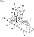
- each of the first conductor part 11 and the second conductor part 12 of the shunt resistor 7 is provided with one board connection terminal 15.
- the board connection terminal 15 of this embodiment is formed of a metal member in the shape of an elongated plate being bent into substantially U-like shape (or C-like shape).
- the board connection terminal 15 has two connecting parts 30 whose proximal end portions are connected via a middle portion 31. More specifically, the middle portion 31 has a substantially linear shape.
- the two connecting parts 30 of the board connection terminal 15 are substantially in parallel to each other. As shown in FIG. 4 , each of the connecting parts 30 is appropriately connected to an electronic circuit mounted on the circuit board 9. Thus, the shunt resistor 7 is electrically connected to the electronic circuit provided on the circuit board 9.
- the circuit board 9 is configured to apply pulse discharge via the board connection terminals 15 and to detect, for example, the intensity of a current having flowed through the resistor element 10 via the board connection terminals 15.
- the casing 8 includes a connector 14 (see FIGS. 1 and 4 ) that outputs a result of the detection.
- the circuit board 9 is connected to an output terminal 32 ( FIG. 4 ) provided in the connector 14, and configured to output a result of the detection through the output terminal 32.
- Another external device for example, an engine control unit (ECU) of an automobile
- ECU engine control unit
- a bolt and a nut are used to connect the battery post terminal 4 and the shunt resistor 7 to each other.
- one of the features of the battery state detection device 1 of this embodiment is that the battery post terminal 4 and the shunt resistor 7 are connected to each other by welding. A more specific description will be given below.
- the battery post terminal 4 of this embodiment includes a shunt resistor connecting part 22 for connection to the second conductor part 12 of the shunt resistor 7.
- the shunt resistor connecting part 22 has its upper surface flat, as shown in FIG. 6 .
- the second conductor part 12 of the shunt resistor 7 is in the shape of a flat plate.
- a lower surface of the second conductor part 12 is flat.
- the flat second conductor part 12 and the flat shunt resistor connecting part 22 are arranged one on the other and welded by an appropriate technique, and thereby they can be connected electrically and mechanically.
- the above-described configuration eliminates the need of the bolt and nut which have been required to connect the battery post terminal 4 and the shunt resistor 7 to each other in the conventional battery state detection device.
- a connection portion where the battery post terminal 4 and the shunt resistor 7 are connected to each other can be made small with respect to its thickness direction as compared with the conventional configuration.
- the connecting portion which is made through welding, has a sufficient strength and a high reliability.
- the shunt resistor connecting part 22 has a flatness of 0.5 mm or less, which enables a mechanical strength of a welded portion to be maintained against impacts, vibrations, and the like.
- the conventional battery state detection device requires the operation of tightening the bolt and nut in order to connect the battery post terminal 4 and the shunt resistor 7 to each other.
- they are connected by welding. This eliminates the need of the operation of tightening a bolt and a nut.
- the welding operation itself is uncomplicated and does not take much time. Accordingly, the battery state detection device 1 can be manufactured for a shortened time.
- the conventional battery state detection device adopts the bolt and nut for connection between the battery post terminal 4 and the shunt resistor 7, which makes it necessary that reception holes for receiving the bolt are formed in the battery post terminal 4, the shunt resistor 7, and the like. Therefore, for example, a change of the design of the battery post terminal 4, which leads to a change of the position where the bolt is inserted, may result in the need to change the design of the shunt resistor 7, too.
- this embodiment adopts welding for connection between the battery post terminal 4 and the shunt resistor 7. Therefore, holes for receiving a bolt for connecting them, and the like, are not required.
- the battery post terminal 4 can be connected to the shunt resistor 7 by welding, as long as the battery post terminal 4 includes the flat-shaped shunt resistor connecting part 22. When, for example, a change of the design of the battery post terminal 4 occurs, the change does not affect the shunt resistor 7. Accordingly, design of the battery state detection device 1 can be changed flexibly.
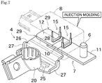
- the casing 8 is injection-molded while a part (the shunt resistor connecting part 22) of the battery post terminal 4 and a part (the second conductor part 12, the resistor element 10, and a portion of the first conductor part 11) of the shunt resistor 7 are inserted.
- Inserting the shunt resistor 7 and the battery post terminal 4 while molding the casing 8 provides improved adhesion of the casing 8 to the shunt resistor 7 and the battery post terminal 4. Accordingly, a situation where a gap between the casing 8 and the shunt resistor 7 or between the casing 8 and the battery post terminal 4 serves as a path of entry of water, is less likely to occur. As a result, waterproofness of the casing 8 can be further improved.
- a boundary between a portion of the battery post terminal 4 exposed to the outside of the casing 8 and a portion of the battery post terminal 4 inserted in the casing 8 will be called an exposure boundary portion 28.
- the exposure boundary portion 28 is positioned between the battery post connecting part 20 and the shunt resistor connecting part 22.
- the exposure boundary portion 28 is not flat (having unevenness), leakage of a resin is likely to occur during formation of the casing 8 with the battery post terminal 4 inserted.
- the battery post terminal 4 is configured such that the exposure boundary portion 28 has a flat plate shape. Since the exposure boundary portion 28 is flat, leakage of a resin during formation of the casing 8 with the battery post terminal 4 inserted can be avoided. As a result, the waterproofness of the casing 8 can be improved.
- the exposure boundary portion 28 has a larger width than that of the shunt resistor connecting part 22.
- the battery post terminal 4 is configured such that the width is increased in a boundary between its portion exposed to the outside of the casing 8 and its portion inserted in the casing 8. Such a configuration ensures a strength because a large area can be ensured as a contact area over which the battery post terminal 4 and the casing 8 are in contact.
- the battery post terminal 4 is arranged such that its portion located at the battery post connecting part 20 side relative to the exposure boundary portion 28 is exposed to the outside of the casing 8.
- the battery post connecting part 20 is exposed to the outside of the casing 8 (not inserted in the casing 8). Therefore, when, for example, a change of the shape of the battery post connecting part 20 occurs, the change does not affect the design of the casing 8. Accordingly, the battery state detection device of this embodiment enables the shape of the battery post connecting part 20 to be changed flexibly.
- a plurality of battery post terminals 4 are prepared whose battery post connecting parts 20 have different shapes each corresponding to each of different vehicle types.
- the plurality of battery post terminals 4 have in common the shape of the portion inserted in the casing 8 (the portion located at the shunt resistor connecting part 22 side relative to the exposure boundary portion 28).
- the design of the casing 8 need not be changed whichever of the battery post terminals 4 is adopted. Accordingly, battery state detection devices having the battery post connecting parts 20 with different shapes each corresponding to each vehicle type are provided at a low cost.
- the shunt resistor 7 and the battery post terminal 4 are provided with bevels 29.
- the shunt resistor 7 and the battery post terminal 4 are inserted in the casing 8, but a resin (the casing 8) and a metal (the shunt resistor 7 and the battery post terminal 4) have different coefficients of linear expansion, and therefore a stress is generated in a joint between them at a time of thermal expansion.
- the portions of the shunt resistor 7 and the battery post terminal 4 inserted in the casing 8 are beveled in advance (bevels 29) as described above, to make angulated portions as small as possible.
- This can prevent the stress generated due to the difference in coefficient of linear expansion from concentrating to a particular region of the casing 8. Accordingly, the durability of the casing 8 can be improved, and the battery state detection device 1 having a high reliability can be provided.
- the board connection terminal 15 is mounted to the shunt resistor 7 by welding. More specifically, as shown in FIG. 5 , the middle portion 31 of the board connection terminal 15 is welded to the shunt resistor 7, and thereby the board connection terminal 15 is (electrically and mechanically) connected to the shunt resistor 7.
- the board connection terminal 15 is mounted to the shunt resistor 7 with a mounting screw.
- an operation of screwing the mounting screw is required. Therefore, it takes time for assembling.
- welding is adopted to mount the board connection terminal 15 to the shunt resistor 7, which eliminates the conventional need for the operation of screwing the mounting screw. As a result, the battery state detection device can be assembled for a further shortened time.
- the harness 5 is connected to the harness connecting part 6 by the nut 18 ( FIG. 1 ) being tightened to the harness connecting part 6.
- the nut 18 FIG. 1
- a torque about the battery post 3 is produced in the battery state detection device 1, as indicated by the bold line in FIG. 1 .
- the battery post terminal 4 is required to have a degree of strength that withstands deformation against the torque.
- the portion inserted in the casing 8 (the portion at the shunt resistor connecting part 22 side relative to the exposure boundary portion 28) is in the shape of a flat plate. That is, the portion inserted in the casing 8, which is in the shape of a flat plate, is compact with respect to the thickness direction. As a result, the casing 8 itself can be made compact.
- the battery post terminal 4 of this embodiment includes a boss portion 25 and a bent portion 26, as shown in FIG. 2 , etc.
- the boss portion 25 and the bent portion 26 are provided in a region (region exposed from the casing 8) between the exposure boundary portion 28 and the battery post connecting part 20.
- the boss portion 25 is formed so as to protrude toward one side with respect to the thickness direction of the shunt resistor connecting part 22 (the direction perpendicular to the drawing plane of FIG. 2 ). When seen in the thickness direction of the shunt resistor connecting part 22 (as shown in FIG. 2 ), the boss portion 25 starts from the battery post connecting part 20 and extends along an imaginary line 40 connecting the battery post connecting part 20 to the harness connecting part 6.
- the bent portion 26 is a portion of the battery post terminal 4 being cranked.
- a "fold" line of the bent portion 26 is substantially in parallel to the longitudinal direction of the shunt resistor 7 (the horizontal direction in FIG. 2 ).
- Reinforcement walls 27 extending in a direction perpendicular to the fold line are provided.
- the reinforcement walls 27 are connected to lateral end surfaces of the bent portion 26.
- the reinforcement walls 27 reinforce a cranked structure of the bent portion 26.
- the presence of the boss portion 25 and the bent portion 26 described above makes the battery post terminal 4 resistant to a torsional force, thus ensuring a strength of the battery post terminal 4. Accordingly, even when a torque is applied to the battery post terminal 4 when the nut 18 is tightened, deformation of the battery post terminal 4 can be prevented.
- the battery post terminal 4 of this embodiment includes a boss portion 25 that, when seen in the thickness direction of the shunt resistor connecting part 22, starts from the battery post connecting part 20 and extends along an imaginary line 41 connecting the battery post connecting part 20 to the connector 14. That is, in the battery post terminal 4 of this embodiment, the boss portions 25 are arranged at two positions.
- the imaginary line 40 and the imaginary line 41 have almost the same length.
- the battery post connecting part 20, the harness connecting part 6, and the connector 14 define the vertices of a substantially isosceles triangle. Therefore, the battery post connecting part 20, the harness connecting part 6, and the connector 14 are arranged in a balanced distribution, with the two boss portions 25 arranged at a proper interval.
- the reinforcement walls 27 are arranged on opposite side portions of the bent portion 26.
- the battery post terminal 4 of this embodiment includes the reinforcement walls 27 provided at two positions.
- the two reinforcement walls 27 are arranged opposed to each other across the axis of symmetry 42 of the isosceles triangle defined by the battery post connecting part 20, the harness connecting part 6, and the connector 14.
- the two boss portions 25 and the two reinforcement walls 27 are arranged in a balanced distribution at proper intervals. Accordingly, even when the torque is applied to the battery post terminal 4, a load is distributed in a proper manner, which further makes the battery post terminal 4 less likely to deform.
- the battery state detection device 1 of this embodiment includes the shunt resistor 7 and the battery post terminal 4.
- the shunt resistor 7 includes the second conductor part 12 having a flat shape.
- the battery post terminal 4 includes the battery post connecting part 20 for connection to the battery post 3, and the shunt resistor connecting part 22 for connection to the second conductor part 12 of the shunt resistor 7.
- the shunt resistor connecting part 22 has a flat shape.
- the second conductor part 12 of the shunt resistor 7 and the shunt resistor connecting part 22 of the battery post terminal 4 are connected to each other by welding.
- the battery state detection device 1 of this embodiment is manufactured through the following manufacturing method.
- the manufacturing method includes a welding step and a casing molding step.
- the welding step the shunt resistor 7 and the battery post terminal 4 are connected to each other by welding.
- the casing molding step the casing 8 is molded while the shunt resistor 7 and the battery post terminal 4 connected to each other by welding are partially inserted.
- connection between the shunt resistor 7 and the battery post terminal 4 is made by welding, the bolt and nut which have been conventionally used for the connection of them are not required.
- the battery state detection device can be downsized as compared with the conventional configuration.
- the connection made by welding is less complicated and can be completed in a shorter time than the operation of tightening the bolt and nut.
- the configuration of this embodiment can shorten a time required for manufacturing the battery state detection device.
- connecting the shunt resistor 7 and the battery post terminal 4 to each other by welding is enabled as long as they have flat portions. Accordingly, the configuration of this embodiment eliminates the need to provide holes for receiving the bolt in the shunt resistor 7 and the casing 8. Therefore, even when, for example, a change of the shape of the battery post terminal 4 occurs, there is no need to change the designs of the shunt resistor 7 and the casing 8. This makes it possible to dynamically adapt to a variety of types of battery post structures.
- the battery post terminal 4 and the shunt resistor 7 are inserted during the molding of the casing 8. This, however, is not limiting. It may be acceptable that, after the casing 8 is molded in the conventional manner, the battery post terminal 4 and the shunt resistor 7 welded to each other are assemble to the casing 8. This also can exert the effect of the invention of the present application because of the elimination of the bolt and nut which have been conventionally required.
- the shapes of the battery post terminal 4, the shunt resistor 7, the casing 8, and the like, are not limited to the illustrated ones, and may be appropriately changed.
Claims (4)
- Dispositif de détection d'état de batterie comprenant :un boîtier (8), une résistance shunt (7) dans le boîtier (8) ; etune borne de batterie (4),la résistance shunt (7) comprenant une partie de conducteur ayant, au moins partiellement,une forme plate, la borne de batterie (4) comprenant :une partie de raccordement de borne de batterie (20) qui doit être raccordée à une borne de batterie, etune partie de raccordement de résistance shunt (22) qui doit être raccordée à la partie de conducteur de la résistance shunt (7), la partie de raccordement de résistance shunt (22) ayant une forme plate,la partie de conducteur de la résistance shunt (7) et la partie de raccordement de résistance shunt (22) de la borne de batterie (4) étant raccordée entre elles par soudage,caractérisé en ce que :la borne de batterie (4) comprend une partie pliée (26) et une paroi de renforcement (27),dans lequel :la partie pliée (27) a une partie déformée prévue entre la partie de raccordement de résistance shunt (22) et la partie de raccordement de borne de batterie (20), etune ligne de pliage de la partie pliée (27) est sensiblement parallèle à la direction longitudinale de la résistance shunt (7), en ce que :
la largeur de la borne de batterie (4) est augmentée dans une limite entre sa partie exposée à l'extérieur du boîtier et sa partie insérée dans le boîtier, et en ce que :
la paroi de renforcement (27) est raccordée à une surface d'extrémité latérale de la partie pliée (26). - Dispositif de détection d'état de batterie selon la revendication 1, comprenant :une carte de circuit imprimé (9) qui détecte un courant qui s'est écoulé à travers la résistance shunt (7) et qui est logée dans le boîtier (8), dans lequel :
le boîtier (8) est moulé alors que la résistance shunt (7) et la borne de batterie (4) raccordées entre elles par soudage, sont au moins partiellement insérées dans le boîtier (8), et dans lequel :la borne de batterie (4) comprend une partie de limite d'exposition (28) ayant une forme plate,la partie de limite d'exposition (28) étant une partie à la limite entre une partie de la borne de batterie (4) insérée dans le boîtier (8) et une partie de la borne de batterie (4) exposée à l'extérieur du boîtier (8). - Dispositif de détection d'état de batterie selon la revendication 2, dans lequel :
des parties de la résistance shunt (7) et de la borne de batterie (4) insérées dans le boîtier (8) sont prévues avec des biseaux (29). - Dispositif de détection d'état de batterie selon la revendication 1, dans lequel :la résistance shunt (7) comprend une partie de raccordement de faisceau (6) qui doit être raccordée à un faisceau (5),la borne de batterie (4) est prévue avec une partie de bossage qui s'étend le long d'une ligne imaginaire raccordant la partie de raccordement de borne de batterie (20) à la partie de raccordement de faisceau (6).
Applications Claiming Priority (2)
| Application Number | Priority Date | Filing Date | Title |
|---|---|---|---|
| JP2013140098 | 2013-07-03 | ||
| PCT/JP2014/003456 WO2015001781A1 (fr) | 2013-07-03 | 2014-06-30 | Appareil de détection d'état de batterie et son procédé de fabrication |
Publications (3)
| Publication Number | Publication Date |
|---|---|
| EP3018754A1 EP3018754A1 (fr) | 2016-05-11 |
| EP3018754A4 EP3018754A4 (fr) | 2017-01-18 |
| EP3018754B1 true EP3018754B1 (fr) | 2018-10-31 |
Family
ID=52143382
Family Applications (1)
| Application Number | Title | Priority Date | Filing Date |
|---|---|---|---|
| EP14819532.4A Active EP3018754B1 (fr) | 2013-07-03 | 2014-06-30 | Appareil de détection d'état de batterie et son procédé de fabrication |
Country Status (6)
| Country | Link |
|---|---|
| US (1) | US10388994B2 (fr) |
| EP (1) | EP3018754B1 (fr) |
| JP (1) | JP6294830B2 (fr) |
| KR (1) | KR102190620B1 (fr) |
| CN (2) | CN108054456A (fr) |
| WO (1) | WO2015001781A1 (fr) |
Families Citing this family (7)
| Publication number | Priority date | Publication date | Assignee | Title |
|---|---|---|---|---|
| WO2017002356A1 (fr) * | 2015-07-01 | 2017-01-05 | 古河電気工業株式会社 | Dispositif de détection d'état de batterie et son procédé de fabrication |
| JP6851803B2 (ja) * | 2016-12-14 | 2021-03-31 | 古河電気工業株式会社 | バッテリー状態検知装置及びその製造方法 |
| JP6559169B2 (ja) * | 2017-02-03 | 2019-08-14 | 矢崎総業株式会社 | バッテリー端子 |
| US20190369143A1 (en) * | 2018-06-05 | 2019-12-05 | Yazaki Corporation | Current sensor |
| JP7237596B2 (ja) * | 2019-01-10 | 2023-03-13 | サンコール株式会社 | シャントセンサ |
| JP7102456B2 (ja) * | 2020-04-13 | 2022-07-19 | 矢崎総業株式会社 | 電流センサ |
| JP7155191B2 (ja) * | 2020-04-13 | 2022-10-18 | 矢崎総業株式会社 | 電流センサ |
Family Cites Families (20)
| Publication number | Priority date | Publication date | Assignee | Title |
|---|---|---|---|---|
| US5619770A (en) * | 1995-11-24 | 1997-04-15 | Flo-Pac Corporation | Rotary pad holder with quick-release mechanism |
| JP2002122203A (ja) * | 2000-10-17 | 2002-04-26 | Minebea Co Ltd | リニアアクチュエータ |
| DE102004053648A1 (de) * | 2004-11-03 | 2006-05-04 | Leopold Kostal Gmbh & Co. Kg | Batteriestromsensor für ein Kraftfahrzeug |
| DE102004055849A1 (de) * | 2004-11-19 | 2006-06-01 | Bayerische Motoren Werke Ag | Batteriesensorvorrichtung |
| DE102004055847B4 (de) * | 2004-11-19 | 2007-01-11 | Bayerische Motoren Werke Ag | Verfahren zur Fertigung einer Batteriesensorvorrichtung |
| FR2879751B1 (fr) | 2004-12-20 | 2007-02-23 | Johnson Controls Tech Co | Dispositif de mesure d'un courant circulant dans un cable |
| JP4639851B2 (ja) * | 2005-03-02 | 2011-02-23 | 株式会社デンソー | 電流センサ付き連結部材 |
| US20080018120A1 (en) * | 2006-07-18 | 2008-01-24 | Bailey Steve | Door Handle Assembly |
| JP2008039571A (ja) * | 2006-08-04 | 2008-02-21 | Denso Corp | 電流センサ |
| DE102006046137B4 (de) * | 2006-09-28 | 2019-02-14 | Continental Automotive Gmbh | Batteriesensoreinheit |
| US7500888B2 (en) * | 2007-02-08 | 2009-03-10 | Lear Corporation | Battery post connector |
| DE112008001413T5 (de) * | 2007-06-04 | 2010-04-29 | Lear Corp., Southfield | Batteriepol-Anschluss |
| US8476864B2 (en) * | 2007-06-13 | 2013-07-02 | Lear Corporation | Battery monitoring system |
| JP2009177903A (ja) * | 2008-01-23 | 2009-08-06 | Denso Corp | 車両システム |
| US8305034B2 (en) * | 2008-07-23 | 2012-11-06 | Lear Corporation | Battery monitoring system |
| JP5582844B2 (ja) * | 2010-03-30 | 2014-09-03 | 古河電気工業株式会社 | バッテリー状態検知センサ |
| JP5723139B2 (ja) * | 2010-04-30 | 2015-05-27 | 矢崎総業株式会社 | 電流センサ付きバッテリターミナルユニット |
| JP5619663B2 (ja) | 2011-03-31 | 2014-11-05 | 古河電気工業株式会社 | シャント抵抗器の接続端子、及びバッテリー状態検知装置 |
| EP2779859B1 (fr) * | 2011-11-14 | 2020-07-08 | Samsonite IP Holdings S.à.r.l. | Bagage compenant un système de protection |
| US20140152313A1 (en) * | 2012-12-03 | 2014-06-05 | Isabellenhuette Heusler Gmbh & Co. Kg | Battery sensor |
-
2014
- 2014-06-30 WO PCT/JP2014/003456 patent/WO2015001781A1/fr active Application Filing
- 2014-06-30 CN CN201810006893.9A patent/CN108054456A/zh active Pending
- 2014-06-30 CN CN201480002185.8A patent/CN104604017B/zh active Active
- 2014-06-30 JP JP2014544281A patent/JP6294830B2/ja active Active
- 2014-06-30 KR KR1020157004951A patent/KR102190620B1/ko active IP Right Grant
- 2014-06-30 US US14/902,340 patent/US10388994B2/en active Active
- 2014-06-30 EP EP14819532.4A patent/EP3018754B1/fr active Active
Non-Patent Citations (1)
| Title |
|---|
| None * |
Also Published As
| Publication number | Publication date |
|---|---|
| KR20160026818A (ko) | 2016-03-09 |
| WO2015001781A1 (fr) | 2015-01-08 |
| CN104604017B (zh) | 2018-05-25 |
| US20160141731A1 (en) | 2016-05-19 |
| CN104604017A (zh) | 2015-05-06 |
| US10388994B2 (en) | 2019-08-20 |
| EP3018754A4 (fr) | 2017-01-18 |
| CN108054456A (zh) | 2018-05-18 |
| JPWO2015001781A1 (ja) | 2017-02-23 |
| EP3018754A1 (fr) | 2016-05-11 |
| JP6294830B2 (ja) | 2018-03-14 |
| KR102190620B1 (ko) | 2020-12-14 |
Similar Documents
| Publication | Publication Date | Title |
|---|---|---|
| EP3018754B1 (fr) | Appareil de détection d'état de batterie et son procédé de fabrication | |
| US7578710B2 (en) | Electrical device | |
| US8147280B2 (en) | Battery post connector | |
| US8305034B2 (en) | Battery monitoring system | |
| JP5137653B2 (ja) | 電流センサ装置 | |
| US10060989B2 (en) | Battery state detection apparatus | |
| EP2485299A1 (fr) | Capteur de détection de l'état d'une batterie | |
| US20170338520A1 (en) | Battery device and battery connection module | |
| EP3300143B1 (fr) | Dispositif de détection d'état de batterie et son procédé de fabrication | |
| CN109075406B (zh) | 温度传感器、电池系统和用于安装电池系统的方法 | |
| EP3196972A1 (fr) | Dispositif capteur de batterie | |
| US20190369143A1 (en) | Current sensor | |
| US20170034938A1 (en) | Wiring module | |
| US20170222282A1 (en) | Battery diagnostic sensor unit | |
| JP5755263B2 (ja) | バッテリー状態検知装置 | |
| JP2005188945A (ja) | 電圧降下式電流計測装置 | |
| US8701476B2 (en) | Sensor assembly with resilient contact portions | |
| KR102150467B1 (ko) | 커버에 전압센싱부재가 설치된 배터리 모듈 | |
| JP4614674B2 (ja) | バッテリートレイ装置 | |
| JP2011141191A (ja) | 電流検出装置 | |
| JP4897914B2 (ja) | バッテリートレイ装置 |
Legal Events
| Date | Code | Title | Description |
|---|---|---|---|
| PUAI | Public reference made under article 153(3) epc to a published international application that has entered the european phase |
Free format text: ORIGINAL CODE: 0009012 |
|
| 17P | Request for examination filed |
Effective date: 20160122 |
|
| AK | Designated contracting states |
Kind code of ref document: A1 Designated state(s): AL AT BE BG CH CY CZ DE DK EE ES FI FR GB GR HR HU IE IS IT LI LT LU LV MC MK MT NL NO PL PT RO RS SE SI SK SM TR |
|
| AX | Request for extension of the european patent |
Extension state: BA ME |
|
| DAX | Request for extension of the european patent (deleted) | ||
| A4 | Supplementary search report drawn up and despatched |
Effective date: 20161219 |
|
| RIC1 | Information provided on ipc code assigned before grant |
Ipc: H01M 10/42 20060101ALN20161213BHEP Ipc: G01R 31/36 20060101ALI20161213BHEP Ipc: H01M 2/20 20060101ALI20161213BHEP Ipc: H01M 2/30 20060101ALI20161213BHEP Ipc: H01M 10/48 20060101AFI20161213BHEP |
|
| RIC1 | Information provided on ipc code assigned before grant |
Ipc: G01R 31/36 20060101ALI20180313BHEP Ipc: H01M 10/42 20060101ALN20180313BHEP Ipc: H01M 2/30 20060101ALI20180313BHEP Ipc: H01M 2/20 20060101ALI20180313BHEP Ipc: H01M 10/48 20060101AFI20180313BHEP |
|
| GRAP | Despatch of communication of intention to grant a patent |
Free format text: ORIGINAL CODE: EPIDOSNIGR1 |
|
| STAA | Information on the status of an ep patent application or granted ep patent |
Free format text: STATUS: GRANT OF PATENT IS INTENDED |
|
| INTG | Intention to grant announced |
Effective date: 20180504 |
|
| RAP1 | Party data changed (applicant data changed or rights of an application transferred) |
Owner name: FURUKAWA AUTOMOTIVE SYSTEMS INC. Owner name: FURUKAWA ELECTRIC CO., LTD. |
|
| GRAJ | Information related to disapproval of communication of intention to grant by the applicant or resumption of examination proceedings by the epo deleted |
Free format text: ORIGINAL CODE: EPIDOSDIGR1 |
|
| STAA | Information on the status of an ep patent application or granted ep patent |
Free format text: STATUS: REQUEST FOR EXAMINATION WAS MADE |
|
| GRAS | Grant fee paid |
Free format text: ORIGINAL CODE: EPIDOSNIGR3 |
|
| STAA | Information on the status of an ep patent application or granted ep patent |
Free format text: STATUS: GRANT OF PATENT IS INTENDED |
|
| GRAP | Despatch of communication of intention to grant a patent |
Free format text: ORIGINAL CODE: EPIDOSNIGR1 |
|
| INTC | Intention to grant announced (deleted) | ||
| GRAA | (expected) grant |
Free format text: ORIGINAL CODE: 0009210 |
|
| STAA | Information on the status of an ep patent application or granted ep patent |
Free format text: STATUS: THE PATENT HAS BEEN GRANTED |
|
| RIC1 | Information provided on ipc code assigned before grant |
Ipc: H01M 10/42 20060101ALN20180830BHEP Ipc: G01R 31/36 20060101ALI20180830BHEP Ipc: H01M 10/48 20060101AFI20180830BHEP Ipc: H01M 2/30 20060101ALI20180830BHEP Ipc: H01M 2/20 20060101ALI20180830BHEP |
|
| INTG | Intention to grant announced |
Effective date: 20180919 |
|
| AK | Designated contracting states |
Kind code of ref document: B1 Designated state(s): AL AT BE BG CH CY CZ DE DK EE ES FI FR GB GR HR HU IE IS IT LI LT LU LV MC MK MT NL NO PL PT RO RS SE SI SK SM TR |
|
| REG | Reference to a national code |
Ref country code: CH Ref legal event code: EP Ref country code: GB Ref legal event code: FG4D |
|
| REG | Reference to a national code |
Ref country code: AT Ref legal event code: REF Ref document number: 1060509 Country of ref document: AT Kind code of ref document: T Effective date: 20181115 |
|
| REG | Reference to a national code |
Ref country code: DE Ref legal event code: R096 Ref document number: 602014035252 Country of ref document: DE |
|
| REG | Reference to a national code |
Ref country code: IE Ref legal event code: FG4D |
|
| REG | Reference to a national code |
Ref country code: NL Ref legal event code: MP Effective date: 20181031 |
|
| REG | Reference to a national code |
Ref country code: LT Ref legal event code: MG4D |
|
| REG | Reference to a national code |
Ref country code: AT Ref legal event code: MK05 Ref document number: 1060509 Country of ref document: AT Kind code of ref document: T Effective date: 20181031 |
|
| PG25 | Lapsed in a contracting state [announced via postgrant information from national office to epo] |
Ref country code: BG Free format text: LAPSE BECAUSE OF FAILURE TO SUBMIT A TRANSLATION OF THE DESCRIPTION OR TO PAY THE FEE WITHIN THE PRESCRIBED TIME-LIMIT Effective date: 20190131 Ref country code: NO Free format text: LAPSE BECAUSE OF FAILURE TO SUBMIT A TRANSLATION OF THE DESCRIPTION OR TO PAY THE FEE WITHIN THE PRESCRIBED TIME-LIMIT Effective date: 20190131 Ref country code: PL Free format text: LAPSE BECAUSE OF FAILURE TO SUBMIT A TRANSLATION OF THE DESCRIPTION OR TO PAY THE FEE WITHIN THE PRESCRIBED TIME-LIMIT Effective date: 20181031 Ref country code: HR Free format text: LAPSE BECAUSE OF FAILURE TO SUBMIT A TRANSLATION OF THE DESCRIPTION OR TO PAY THE FEE WITHIN THE PRESCRIBED TIME-LIMIT Effective date: 20181031 Ref country code: LV Free format text: LAPSE BECAUSE OF FAILURE TO SUBMIT A TRANSLATION OF THE DESCRIPTION OR TO PAY THE FEE WITHIN THE PRESCRIBED TIME-LIMIT Effective date: 20181031 Ref country code: AT Free format text: LAPSE BECAUSE OF FAILURE TO SUBMIT A TRANSLATION OF THE DESCRIPTION OR TO PAY THE FEE WITHIN THE PRESCRIBED TIME-LIMIT Effective date: 20181031 Ref country code: IS Free format text: LAPSE BECAUSE OF FAILURE TO SUBMIT A TRANSLATION OF THE DESCRIPTION OR TO PAY THE FEE WITHIN THE PRESCRIBED TIME-LIMIT Effective date: 20190228 Ref country code: FI Free format text: LAPSE BECAUSE OF FAILURE TO SUBMIT A TRANSLATION OF THE DESCRIPTION OR TO PAY THE FEE WITHIN THE PRESCRIBED TIME-LIMIT Effective date: 20181031 Ref country code: ES Free format text: LAPSE BECAUSE OF FAILURE TO SUBMIT A TRANSLATION OF THE DESCRIPTION OR TO PAY THE FEE WITHIN THE PRESCRIBED TIME-LIMIT Effective date: 20181031 Ref country code: LT Free format text: LAPSE BECAUSE OF FAILURE TO SUBMIT A TRANSLATION OF THE DESCRIPTION OR TO PAY THE FEE WITHIN THE PRESCRIBED TIME-LIMIT Effective date: 20181031 |
|
| PG25 | Lapsed in a contracting state [announced via postgrant information from national office to epo] |
Ref country code: PT Free format text: LAPSE BECAUSE OF FAILURE TO SUBMIT A TRANSLATION OF THE DESCRIPTION OR TO PAY THE FEE WITHIN THE PRESCRIBED TIME-LIMIT Effective date: 20190301 Ref country code: SE Free format text: LAPSE BECAUSE OF FAILURE TO SUBMIT A TRANSLATION OF THE DESCRIPTION OR TO PAY THE FEE WITHIN THE PRESCRIBED TIME-LIMIT Effective date: 20181031 Ref country code: NL Free format text: LAPSE BECAUSE OF FAILURE TO SUBMIT A TRANSLATION OF THE DESCRIPTION OR TO PAY THE FEE WITHIN THE PRESCRIBED TIME-LIMIT Effective date: 20181031 Ref country code: GR Free format text: LAPSE BECAUSE OF FAILURE TO SUBMIT A TRANSLATION OF THE DESCRIPTION OR TO PAY THE FEE WITHIN THE PRESCRIBED TIME-LIMIT Effective date: 20190201 Ref country code: AL Free format text: LAPSE BECAUSE OF FAILURE TO SUBMIT A TRANSLATION OF THE DESCRIPTION OR TO PAY THE FEE WITHIN THE PRESCRIBED TIME-LIMIT Effective date: 20181031 Ref country code: RS Free format text: LAPSE BECAUSE OF FAILURE TO SUBMIT A TRANSLATION OF THE DESCRIPTION OR TO PAY THE FEE WITHIN THE PRESCRIBED TIME-LIMIT Effective date: 20181031 |
|
| PG25 | Lapsed in a contracting state [announced via postgrant information from national office to epo] |
Ref country code: CZ Free format text: LAPSE BECAUSE OF FAILURE TO SUBMIT A TRANSLATION OF THE DESCRIPTION OR TO PAY THE FEE WITHIN THE PRESCRIBED TIME-LIMIT Effective date: 20181031 Ref country code: DK Free format text: LAPSE BECAUSE OF FAILURE TO SUBMIT A TRANSLATION OF THE DESCRIPTION OR TO PAY THE FEE WITHIN THE PRESCRIBED TIME-LIMIT Effective date: 20181031 Ref country code: IT Free format text: LAPSE BECAUSE OF FAILURE TO SUBMIT A TRANSLATION OF THE DESCRIPTION OR TO PAY THE FEE WITHIN THE PRESCRIBED TIME-LIMIT Effective date: 20181031 |
|
| REG | Reference to a national code |
Ref country code: DE Ref legal event code: R097 Ref document number: 602014035252 Country of ref document: DE |
|
| PG25 | Lapsed in a contracting state [announced via postgrant information from national office to epo] |
Ref country code: EE Free format text: LAPSE BECAUSE OF FAILURE TO SUBMIT A TRANSLATION OF THE DESCRIPTION OR TO PAY THE FEE WITHIN THE PRESCRIBED TIME-LIMIT Effective date: 20181031 Ref country code: SM Free format text: LAPSE BECAUSE OF FAILURE TO SUBMIT A TRANSLATION OF THE DESCRIPTION OR TO PAY THE FEE WITHIN THE PRESCRIBED TIME-LIMIT Effective date: 20181031 Ref country code: RO Free format text: LAPSE BECAUSE OF FAILURE TO SUBMIT A TRANSLATION OF THE DESCRIPTION OR TO PAY THE FEE WITHIN THE PRESCRIBED TIME-LIMIT Effective date: 20181031 Ref country code: SK Free format text: LAPSE BECAUSE OF FAILURE TO SUBMIT A TRANSLATION OF THE DESCRIPTION OR TO PAY THE FEE WITHIN THE PRESCRIBED TIME-LIMIT Effective date: 20181031 |
|
| PLBE | No opposition filed within time limit |
Free format text: ORIGINAL CODE: 0009261 |
|
| STAA | Information on the status of an ep patent application or granted ep patent |
Free format text: STATUS: NO OPPOSITION FILED WITHIN TIME LIMIT |
|
| 26N | No opposition filed |
Effective date: 20190801 |
|
| PG25 | Lapsed in a contracting state [announced via postgrant information from national office to epo] |
Ref country code: SI Free format text: LAPSE BECAUSE OF FAILURE TO SUBMIT A TRANSLATION OF THE DESCRIPTION OR TO PAY THE FEE WITHIN THE PRESCRIBED TIME-LIMIT Effective date: 20181031 |
|
| PG25 | Lapsed in a contracting state [announced via postgrant information from national office to epo] |
Ref country code: MC Free format text: LAPSE BECAUSE OF FAILURE TO SUBMIT A TRANSLATION OF THE DESCRIPTION OR TO PAY THE FEE WITHIN THE PRESCRIBED TIME-LIMIT Effective date: 20181031 |
|
| REG | Reference to a national code |
Ref country code: CH Ref legal event code: PL |
|
| GBPC | Gb: european patent ceased through non-payment of renewal fee |
Effective date: 20190630 |
|
| REG | Reference to a national code |
Ref country code: BE Ref legal event code: MM Effective date: 20190630 |
|
| PG25 | Lapsed in a contracting state [announced via postgrant information from national office to epo] |
Ref country code: TR Free format text: LAPSE BECAUSE OF FAILURE TO SUBMIT A TRANSLATION OF THE DESCRIPTION OR TO PAY THE FEE WITHIN THE PRESCRIBED TIME-LIMIT Effective date: 20181031 |
|
| PG25 | Lapsed in a contracting state [announced via postgrant information from national office to epo] |
Ref country code: IE Free format text: LAPSE BECAUSE OF NON-PAYMENT OF DUE FEES Effective date: 20190630 Ref country code: GB Free format text: LAPSE BECAUSE OF NON-PAYMENT OF DUE FEES Effective date: 20190630 |
|
| PG25 | Lapsed in a contracting state [announced via postgrant information from national office to epo] |
Ref country code: LU Free format text: LAPSE BECAUSE OF NON-PAYMENT OF DUE FEES Effective date: 20190630 Ref country code: BE Free format text: LAPSE BECAUSE OF NON-PAYMENT OF DUE FEES Effective date: 20190630 Ref country code: CH Free format text: LAPSE BECAUSE OF NON-PAYMENT OF DUE FEES Effective date: 20190630 Ref country code: LI Free format text: LAPSE BECAUSE OF NON-PAYMENT OF DUE FEES Effective date: 20190630 |
|
| PG25 | Lapsed in a contracting state [announced via postgrant information from national office to epo] |
Ref country code: FR Free format text: LAPSE BECAUSE OF NON-PAYMENT OF DUE FEES Effective date: 20190630 |
|
| PG25 | Lapsed in a contracting state [announced via postgrant information from national office to epo] |
Ref country code: CY Free format text: LAPSE BECAUSE OF FAILURE TO SUBMIT A TRANSLATION OF THE DESCRIPTION OR TO PAY THE FEE WITHIN THE PRESCRIBED TIME-LIMIT Effective date: 20181031 |
|
| PG25 | Lapsed in a contracting state [announced via postgrant information from national office to epo] |
Ref country code: HU Free format text: LAPSE BECAUSE OF FAILURE TO SUBMIT A TRANSLATION OF THE DESCRIPTION OR TO PAY THE FEE WITHIN THE PRESCRIBED TIME-LIMIT; INVALID AB INITIO Effective date: 20140630 Ref country code: MT Free format text: LAPSE BECAUSE OF FAILURE TO SUBMIT A TRANSLATION OF THE DESCRIPTION OR TO PAY THE FEE WITHIN THE PRESCRIBED TIME-LIMIT Effective date: 20181031 |
|
| PG25 | Lapsed in a contracting state [announced via postgrant information from national office to epo] |
Ref country code: MK Free format text: LAPSE BECAUSE OF FAILURE TO SUBMIT A TRANSLATION OF THE DESCRIPTION OR TO PAY THE FEE WITHIN THE PRESCRIBED TIME-LIMIT Effective date: 20181031 |
|
| P01 | Opt-out of the competence of the unified patent court (upc) registered |
Effective date: 20230512 |
|
| PGFP | Annual fee paid to national office [announced via postgrant information from national office to epo] |
Ref country code: DE Payment date: 20230502 Year of fee payment: 10 |