EP3018368A2 - Doppelhaken und systeme - Google Patents
Doppelhaken und systeme Download PDFInfo
- Publication number
- EP3018368A2 EP3018368A2 EP15187962.4A EP15187962A EP3018368A2 EP 3018368 A2 EP3018368 A2 EP 3018368A2 EP 15187962 A EP15187962 A EP 15187962A EP 3018368 A2 EP3018368 A2 EP 3018368A2
- Authority
- EP
- European Patent Office
- Prior art keywords
- hook
- perforation
- positively
- double
- rod
- Prior art date
- Legal status (The legal status is an assumption and is not a legal conclusion. Google has not performed a legal analysis and makes no representation as to the accuracy of the status listed.)
- Granted
Links
Images

Classifications
-
- F—MECHANICAL ENGINEERING; LIGHTING; HEATING; WEAPONS; BLASTING
- F16—ENGINEERING ELEMENTS AND UNITS; GENERAL MEASURES FOR PRODUCING AND MAINTAINING EFFECTIVE FUNCTIONING OF MACHINES OR INSTALLATIONS; THERMAL INSULATION IN GENERAL
- F16B—DEVICES FOR FASTENING OR SECURING CONSTRUCTIONAL ELEMENTS OR MACHINE PARTS TOGETHER, e.g. NAILS, BOLTS, CIRCLIPS, CLAMPS, CLIPS OR WEDGES; JOINTS OR JOINTING
- F16B45/00—Hooks; Eyes
- F16B45/005—Hooks; Eyes characterised by the material
- F16B45/008—Hooks; Eyes characterised by the material plastics
-
- F—MECHANICAL ENGINEERING; LIGHTING; HEATING; WEAPONS; BLASTING
- F16—ENGINEERING ELEMENTS AND UNITS; GENERAL MEASURES FOR PRODUCING AND MAINTAINING EFFECTIVE FUNCTIONING OF MACHINES OR INSTALLATIONS; THERMAL INSULATION IN GENERAL
- F16B—DEVICES FOR FASTENING OR SECURING CONSTRUCTIONAL ELEMENTS OR MACHINE PARTS TOGETHER, e.g. NAILS, BOLTS, CIRCLIPS, CLAMPS, CLIPS OR WEDGES; JOINTS OR JOINTING
- F16B45/00—Hooks; Eyes
- F16B45/002—Eyes
-
- F—MECHANICAL ENGINEERING; LIGHTING; HEATING; WEAPONS; BLASTING
- F16—ENGINEERING ELEMENTS AND UNITS; GENERAL MEASURES FOR PRODUCING AND MAINTAINING EFFECTIVE FUNCTIONING OF MACHINES OR INSTALLATIONS; THERMAL INSULATION IN GENERAL
- F16B—DEVICES FOR FASTENING OR SECURING CONSTRUCTIONAL ELEMENTS OR MACHINE PARTS TOGETHER, e.g. NAILS, BOLTS, CIRCLIPS, CLAMPS, CLIPS OR WEDGES; JOINTS OR JOINTING
- F16B5/00—Joining sheets or plates, e.g. panels, to one another or to strips or bars parallel to them
- F16B5/06—Joining sheets or plates, e.g. panels, to one another or to strips or bars parallel to them by means of clamps or clips
- F16B5/0685—Joining sheets or plates to strips or bars
Definitions
- the present invention relates to double hooks for releasable hooking into a perforation, comprising at a first end a first hook and at a second end a second hook.
- Double hooks especially S-hooks, which are hooked with one of their hooks in a perforation and on the second hook any other element can be fastened, are known.
- These double hooks are suspended, for example, with a hook in a perforation of a ceiling clip, wherein the ceiling clip is attached to a profile of a substructure of a ceiling covering, such as a Odenwalddecke, and on the second hook, an element is attached.
- the loading of the element may result in either the ceiling clip being destroyed or, if the ceiling clip is not destroyed, the profile of the ceiling structure being damaged.
- a double hook for detachable hooking into a perforation comprising at a first end a first hook and at a second end a second hook, characterized in that the first hook is open or closed and the second hook has an opening for positive and / or non-positive connection with the perforation, wherein the second hook separates from the perforation when a defined tensile force is exceeded.
- the perforation is formed on the ceiling clip.
- This perforation can be present as an opening or as a hole in the ceiling clip or be formed as a closed bracket on the ceiling clip.
- the task for a double hook for releasably hooking into a perforation comprising at a first end a first hook and at a second end a second hook, achieved in that the second hook is open or closed, wherein the second hook for connecting is provided with the perforation, and the first hook having an opening for positive and / or non-positive connection with a member, wherein the first hook dissolves when exceeding a predetermined tensile force of the element.
- the object is also for a double hook for releasably attaching to a rod, wherein the rod is positively and / or non-positively attached to a perforation, comprising at a first end a first hook and at a second end a second hook, solved in that the first hook is designed to be open or closed and the second hook has an opening for positive and / or non-positive connection with the rod, wherein the second hook detaches from the rod when a defined tensile force is exceeded.
- the task for a double hook for releasably attaching to a rod wherein the rod is positively and / or non-positively attached to a perforation, comprising at a first end a first hook and at a second end a second hook, achieved in that the second hook is open or closed, wherein the second hook is provided for connection to the rod, and the first hook has an opening for positive and / or non-positive connection with a member, wherein the first hook when exceeding a predetermined tensile force detached from the element.
- an element is arranged, wherein the element is an extension hook, a soundproofing curtain, a decorative panel or a privacy curtain.
- An embodiment of the invention provides that an extension hook is arranged on the double hook, wherein the extension hook at a first end has an open or closed hook and at a second end a receiving arrangement, so that one of the hooks of the double hook positively and non-positively in the recording arrangement can be kept.
- the hook as described above, has an opening for positive and / or non-positive connection, which dissolves when a defined tensile force from the element, the rod or the perforation is exceeded, it can be avoided that in the case when the patient is supported on the soundproofing curtain, the decorative panels or the privacy curtain, not the entire element (including the ceiling construction) is demolished, but only the loaded hook is detached from the ceiling clip.
- An advantageous embodiment of the invention provides that the opening of the hook, which has an opening for the positive and / or non-positive connection, is arranged on a longitudinal axis, wherein the longitudinal axis extends through the centers of the first and the second hook.
- the opening of the hook is formed by two elastic wall sections connected to one side, between whose free ends the opening is located.
- the opening is arranged at the point at which the hook is connected to either the perforation of the ceiling clip, a rod or with an eyelet or loop of the element.
- the hook over its opening positively and / or non-positively connected with the perforation of the ceiling clip, the rod or with the eyelet / loop of the element.
- the hook For attaching the hook to the element or the perforation, the hook is connected by applying pressure, wherein the two wall sections bend elastically. As soon as the two wall sections engage in the perforation or the eyelet / loop, they return to their original shape.
- the opening of the hook which has an opening for positive and / or non-positive connection, at an angle of 30 ° to 150 °, preferably at an angle 60 ° to 120 °, preferably at an angle is arranged from 85 ° to 95 ° relative to a longitudinal axis, wherein the longitudinal axis extends through the centers of the first and the second hook.
- the two wall sections are formed such that they bend at a tensile force on the hook, which is greater than the predetermined tensile force, such that the opening is increased, whereby the hook of the perforation of the ceiling clip, the rod or the eyelet / loop of the element releases.
- the double hook is formed in one piece and made of plastic - in particular polyamide -, metal or rubber.
- the desired elasticity values can be set to the maximum tensile force.
- An embodiment of the invention provides that the wall sections bend at a tensile force of 1.1 kilograms.
- the object of the invention is also for a system for fastening elements to a profile of a substructure of a ceiling panel comprising a ceiling clip with a perforation, which is positively and / or non-positively fastened to a profile of a substructure of a ceiling panel, and a double hook comprising at a first end a first hook and at a second end a second hook, wherein the double hook with the perforation of the ceiling clip form and / or can be positively connected, achieved in that the first hook is open or closed and the second hook has an opening for positive and / or non-positive connection with the perforation, wherein the second hook solves when exceeding a predetermined tensile force from the perforation.
- the object is achieved in that the second hook is open or closed, wherein the second hook is provided for connection to the perforation, and the first hook has an opening for positive and / or non-positive connection having an element, wherein the first hook detached from the element when a specified tensile force is exceeded.
- the object of the invention is also for a system for fixing elements to a profile of a substructure of a ceiling panel comprising a ceiling clip with a perforation, which is positively and / or non-positively fastened to a profile of a substructure of a ceiling panel, a rod to the the perforation of the ceiling clip is positively and / or non-positively fastened and a double hook, comprising at a first end a first hook and at a second end a second hook, the double hook with the rod form and / or non-positively connected, thereby solved in that the first hook is designed to be open or closed and the second hook has an opening for positive and / or non-positive connection to the rod, wherein the second hook is released from the rod when a defined tensile force is exceeded.
- the object is achieved in that the second hook is open or closed, wherein the second hook is provided for connection to the rod, and the first hook an opening for positive and / or non-positive connection having a member, wherein the first hook dissolves when exceeding a predetermined tensile force of the element.
- an element can be arranged on one of the hooks, wherein the element is an extension hook, a soundproofing curtain, a decorative panel or a privacy curtain.
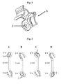
- a ceiling clip (6) with a perforation (2) is shown in a perspective view.
- the ceiling clip (6) has two grooves in the transverse plane.
- the grooves are arranged on two transverse (right and left) to the sagittal plane compression springs in the upper region (longitudinal to the transverse plane).
- the ceiling clip can therefore be arranged on a profile of a substructure of a ceiling arrangement and are fixed by releasing positive and non-positive on this.
- the perforation (2) is arranged on a medially arranged projection below the grooves.
- the perforation (2) is circular in the illustrated embodiment Opening shown. However, it is also conceivable that the perforation is designed as an open or closed hook.
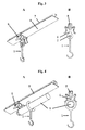
- Fig. 2 A shows here a double hook (1) for releasable hooking in a perforation, comprising at a first end a first hook (3) and at a second end a second hook (4), wherein the first hook (3) is open or closed and the second hook (4) has an opening (5) for positive and / or non-positive connection with the perforation (2).
- the opening (5) of the hook (4) is arranged at an angle of 30 ° to 150 ° with respect to a longitudinal axis.
- the longitudinal axis extends through the centers of the respective hooked by the hook shape surfaces of the first hook (3) and the second hook (4). It is envisaged that the second hook (4) detaches from the perforation (2) when a defined tensile force is exceeded.
- Fig. 2 B shows a double hook (1) for releasably hooking into a perforation, comprising at a first end a first hook (3) and at a second end a second hook (4), wherein the second hook (4) is open or closed formed and the Connecting with the perforation is provided, and the first hook (3) has an opening (5) for positive and / or non-positive connection with an element.
- the opening (5) of the hook (3) is arranged on a longitudinal axis, wherein the longitudinal axis extends through the respectively formed surface centers of the first hook (3) and the second hook (4). It is hereby provided that the first hook (3) dissolves when exceeding a specified tensile force of the element.
- Fig. 2C shows a double hook (1) for releasably attaching to a rod, wherein the rod at a perforation (2) is positively and / or non-positively attached, comprising at a first end a first hook (3) and at a second end a second hook (4), wherein the first hook (3) is open or closed and the second hook (4) has an opening (5) for positive and / or non-positive connection with the rod.
- the opening (5) of the hook (4) is arranged on a longitudinal axis, wherein the longitudinal axis extends through the respectively formed surface centers of the first hook (3) and the second hook (4). It is envisaged that the second hook (4) detaches from the rod when a specified tensile force is exceeded.
- Fig. 2 D shows a double hook (1) for releasable attachment to a rod, wherein the rod is positively and / or non-positively attached to a perforation, comprising at a first end a first hook (3) and at a second end a second hook (4) wherein the second hook (4) is formed open or closed and is provided for connection to the rod, and the first hook (3) has an opening (5) for positive and / or non-positive connection with a member, wherein the first hook (3) releases from the element when a defined tensile force is exceeded.
- the opening (5) of the hook (3) is arranged at an angle of 30 ° to 150 with respect to a longitudinal axis. The longitudinal axis extends through the centers of the respective hooked by the hook shape surfaces of the first hook (3) and the second hook (4).
- Fig. 3 A is a system for attaching elements to a profile (7) of a substructure (8) of a ceiling panel comprising a ceiling clip (6) with a perforation, which on a profile (7) of a substructure (8) form a ceiling panel form and / or can be fixed non-positively, and a double hook (1), comprising at a first end a first hook and at a second end a second hook, the double hook (1) with the perforation of the ceiling clip (6) positively and / or non-positively connectable shown in perspective view.
- the first hook (the lower hook of the double hook (1)) is open or closed and the second hook has an opening for positive and / or non-positive connection with the perforation. It is envisaged that the second hook (4) detaches from the perforation when a defined tensile force is exceeded.
- Fig. 3B shows the system just described in side view.
- Fig. 4 A is a system for securing elements to a profile (7) of a substructure (8) of a ceiling panel, comprising a ceiling clip with a perforation which on a profile (7) of a substructure (8) of a ceiling panel form and / or non-positively fastened a rod (9) which can be fixed positively and / or non-positively to the perforation of the ceiling clip (6) and a double hook (1) comprising at a first end a first hook and at a second end a second hook, wherein the Double hook (1) with the rod (9) positively and / or non-positively connectable is shown in a perspective view.
- the first hook (the lower hook of the double hook (1)) is open or closed and the second Hook has an opening for positive and / or non-positive connection with the rod (9).
- the double hook (1) along the rod (9) can be performed.
- an end piece whose diameter is greater than the inner diameter of the hook, with the shape of the rod - and / or non-positively connected, can be arranged at the end of the rod (9). It is provided for this system that the second hook disengages from the rod (9) when a specified tensile force is exceeded.
- Fig. 4B shows the system just described in side view.
- Fig. 5 is that in Fig. 3 described system in side view ( Fig. 5 A) and in perspective view ( Fig. 5B ).
- an extension hook (10) non-positively and positively arranged on the double hook (1).
- the extension hook (10) has an open or closed hook at one end and an approximately hook-shaped receiving arrangement at the opposite end, so that the extension hook can be positively and non-positively connected to a further hook (of a double hook or extension hook).
- the distance to the ceiling clip (6) which is arranged on the substructure (8) can be set arbitrarily.
- a plurality of extension hooks (10) are interconnected.
- a soundproofing curtain, a decorative panel or a privacy curtain can be attached to the double hook (1).
Landscapes
- Engineering & Computer Science (AREA)
- General Engineering & Computer Science (AREA)
- Mechanical Engineering (AREA)
- Curtains And Furnishings For Windows Or Doors (AREA)
- Hooks, Suction Cups, And Attachment By Adhesive Means (AREA)
- Supports Or Holders For Household Use (AREA)
Abstract
Description
- Die vorliegende Erfindung betrifft Doppelhaken zum lösbaren Einhängen in eine Perforation, umfassend an einem ersten Ende einen ersten Haken und an einem zweiten Ende einen zweiten Haken.
- Doppelhaken, insbesondere S-Haken, die mit einem ihrer Haken in eine Perforation eingehängt werden und an deren zweiten Haken ein beliebiges weiteres Element befestigbar ist, sind bekannt.
- Diese Doppelhaken werden beispielsweise mit einem Haken in eine Perforation eines Deckenclips eingehängt, wobei der Deckenclip an einem Profil einer Unterkonstruktion einer Deckenverkleidung, wie beispielsweise einer Odenwalddecke, angebracht ist, und an dem zweiten Haken wird ein Element befestigt.
- Nachteilig bei den bekannten Doppelhaken ist, dass sie derart starr ausgebildet sind, dass wenn an dem befestigten Element gezogen wird, der Deckenclip, oder sogar das gesamte Profil der Unterkonstruktion der Deckenverkleidung, mit der Zugkraft belastet wird.
- In einem ungünstigen Fall kann die Belastung des Elementes dazu führen, dass entweder der Deckenclip zerstört wird oder, falls der Deckenclip nicht zerstört wird, das Profil der Deckenkonstruktion beschädigt wird.
- Ein derartiger Schaden muss dann behoben werden, was mit hohen Kosten verbunden ist.
- Es ist daher die Aufgabe der Erfindung, Doppelhaken sowie Systeme bereitzustellen, die es ermöglichen, oben beschriebene Probleme zu vermeiden.
- Die Aufgabe wird für einen Doppelhaken zum lösbaren Einhängen in eine Perforation, umfassend an einem ersten Ende einen ersten Haken und an einem zweiten Ende einen zweiten Haken, dadurch gelöst, dass der erste Haken offen oder geschlossen ausgebildet ist und der zweite Haken eine Öffnung zum form- und/oder kraftschlüssigen Verbinden mit der Perforation aufweist, wobei sich der zweite Haken bei Überschreiten einer festgelegten Zugkraft von der Perforation löst.
- Die Perforation ist an dem Deckenclip ausgebildet. Diese Perforation kann als eine Öffnung bzw. als Loch in dem Deckenclip vorliegen oder als geschlossener Bügel an dem Deckenclip ausgebildet sein.
- Ebenso wird die Aufgabe für einen Doppelhaken zum lösbaren Einhängen in eine Perforation, umfassend an einem ersten Ende einen ersten Haken und an einem zweiten Ende einen zweiten Haken, dadurch gelöst, dass der zweite Haken offen oder geschlossen ausgebildet ist, wobei der zweite Haken zum Verbinden mit der Perforation vorgesehen ist, und der erste Haken eine Öffnung zum form- und/oder kraftschlüssigen Verbinden mit einem Element aufweist, wobei sich der erste Haken bei Überschreiten einer festgelegten Zugkraft von dem Element löst.
- Die Aufgabe wird ebenfalls für einen Doppelhaken zum lösbaren Befestigen an einer Stange, wobei die Stange an einer Perforation form- und/oder kraftschlüssig befestigt ist, umfassend an einem ersten Ende einen ersten Haken und an einem zweiten Ende einen zweiten Haken, dadurch gelöst, dass der erste Haken offen oder geschlossen ausgebildet ist und der zweite Haken eine Öffnung zum form- und/oder kraftschlüssigen Verbinden mit der Stange aufweist, wobei sich der zweite Haken bei Überschreiten einer festgelegten Zugkraft von dem Stange löst.
- Ebenso wird die Aufgabe für einen Doppelhaken zum lösbaren Befestigen an einer Stange, wobei die Stange an einer Perforation form- und/oder kraftschlüssig befestigt ist, umfassend an einem ersten Ende einen ersten Haken und an einem zweiten Ende einen zweiten Haken, dadurch gelöst, dass der zweite Haken offen oder geschlossen ausgebildet ist, wobei der zweite Haken zum Verbinden mit der Stange vorgesehen ist, und der erste Haken eine Öffnung zum form- und/oder kraftschlüssigen Verbinden mit einem Element aufweist, wobei sich der erste Haken bei Überschreiten einer festgelegten Zugkraft von dem Element löst.
- In Krankenhäusern werden Patienten auf Grund von Platzmangel oftmals nicht in separaten Räumen behandelt. Um zu gewährleisten, dass andere Patienten die Behandlung des Arztes nicht wahrnehmen, werden oftmals Vorhänge, die über Deckenclips an einem Profil einer Unterkonstruktion einer Deckenverkleidung befestigt werden, verwendet, die die Privatsphäre des Patienten schützen sollen. Ebenso gibt es Vorhänge, die an Stangen geführt werden, wobei die Stangen an Deckenclips an einem Profil einer Unterkonstruktion einer Deckenverkleidung befestigt werden.
- Es ist daher zu der Erfindung gehörig, dass an dem Haken ein Element angeordnet ist, wobei das Element ein Verlängerungshaken, ein Schallschutzvorhang, eine Dekorationspaneele oder ein Sichtschutzvorhang ist.
- Hierbei sieht eine Ausgestaltung der Erfindung vor, dass an dem Doppelhaken ein Verlängerungshaken angeordnet ist, wobei der Verlängerungshaken an einem ersten Ende einen offenen oder geschlossenen Haken und an einem zweiten Ende eine Aufnahmeanordnung aufweist, so dass einer der Haken des Doppelhakens form- und kraftschlüssig in der Aufnahmeanordnung gehalten werden kann.
- Da der Haken, wie oben beschrieben, eine Öffnung zum form- und/oder kraftschlüssigen Verbinden aufweist, die sich bei Überschreiten einer festgelegten Zugkraft von dem Element, der Stange oder der Perforation löst, kann vermieden werden, dass im Falle, wenn der Patient sich an dem Schallschutzvorhang, der Dekorationspaneele oder dem Sichtschutzvorhang abstützt, nicht das gesamte Element (inklusive der Deckenkonstruktion) abgerissen wird, sondern lediglich der belastete Haken von dem Deckenclip abgelöst wird.
- Eine vorteilhafte Ausgestaltung der Erfindung sieht vor, dass die Öffnung des Hakens, der eine Öffnung zum form- und/oder kraftschlüssigen Verbinden aufweist, auf einer Längsachse angeordnet ist, wobei die Längsachse durch die Mittelpunkte des ersten und des zweiten Hakens verläuft.
- Die Öffnung des Hakens wird durch zwei an einer Seite verbundene elastische Wandabschnitte gebildet, zwischen deren freien Enden sich die Öffnung befindet. In der beschriebenen Ausgestaltung ist die Öffnung an der Stelle angeordnet, an der der Haken entweder mit der Perforation des Deckenclips, einer Stange oder mit einer Öse oder Schlaufe des Elementes verbunden ist. Hierbei ist vorgesehen, dass der Haken über seine Öffnung form- und/oder kraftschlüssig mit der Perforation des Deckenclips, der Stange oder mit der Öse/Schlaufe des Elements verbindbar ist.
- Zum Befestigen des Hakens an dem Element oder der Perforation wird der Haken unter Ausübung von Druck, wobei sich die beiden Wandabschnitte elastisch verbiegen, verbunden. Sobald die beiden Wandabschnitte in die Perforation oder die Öse/Schlaufe eingreifen, gehen diese in ihre Ursprungsform zurück.
- Es liegt im Rahmen der Erfindung, dass die Öffnung des Hakens, der eine Öffnung zum form- und/oder kraftschlüssigen Verbinden aufweist, in einem Winkel von 30° bis 150°, vorzugsweise in einem Winkel 60° bis 120°, bevorzugt in einem Winkel von 85° bis 95° gegenüber einer Längsachse angeordnet ist, wobei die Längsachse durch die Mittelpunkte des ersten und des zweiten Hakens verläuft.
- Hierbei ist vorgesehen, dass die beiden Wandabschnitte derart ausgebildet sind, dass sie bei einer Zugkraft an dem Haken, die größer ist als die vorbestimmte Zugkraft, derart verbiegen, dass die Öffnung vergrößert wird, wodurch sich der Haken von der Perforation des Deckenclips, der Stange oder der Öse/Schlaufe des Elements löst.
- Dementsprechend ist vorteilhaft vorgesehen, dass der Doppelhaken einstückig ausgebildet ist und aus Kunststoff - insbesondere Polyamid -, Metall oder Gummi besteht.
- Die Materialeigenschaften dieser Materialien sind bekannt. Dementsprechend lassen sich die gewünschten Elastizitätswerte auf die maximale Zugkraft einstellen.
- Eine Ausgestaltung der Erfindung sieht vor, dass sich die Wandabschnitte bei einer Zugkraft von 1,1 Kilogramm verbiegen.
- Die Aufgabe der Erfindung wird ebenfalls für ein System zum Befestigen von Elementen an einem Profil einer Unterkonstruktion einer Deckenverkleidung, umfassend einen Deckenclip mit einer Perforation, welcher an einem Profil einer Unterkonstruktion einer Deckenverkleidung form- und/oder kraftschlüssig befestigbar ist, und einen Doppelhaken, umfassend an einem ersten Ende einen ersten Haken und an einem zweiten Ende einen zweiten Haken, wobei der Doppelhaken mit der Perforation des Deckenclips form- und/oder kraftschlüssig verbindbar ist, dadurch gelöst, dass der erste Haken offen oder geschlossen ausgebildet ist und der zweite Haken eine Öffnung zum form- und/oder kraftschlüssigen Verbinden mit der Perforation aufweist, wobei sich der zweite Haken bei Überschreiten einer festgelegten Zugkraft von der Perforation löst.
- Es ist natürlich ebenso vorstellbar, dass die Aufgabe dadurch gelöst wird, dass der zweite Haken offen oder geschlossen ausgebildet ist, wobei der zweite Haken zum Verbinden mit der Perforation vorgesehen ist, und der erste Haken eine Öffnung zum form- und/oder kraftschlüssigen Verbinden mit einem Element aufweist, wobei sich der erste Haken bei Überschreiten einer festgelegten Zugkraft von dem Element löst.
- Die Aufgabe der Erfindung wird ebenfalls für ein System zum Befestigen von Elementen an einem Profil einer Unterkonstruktion einer Deckenverkleidung, umfassend einen Deckenclip mit einer Perforation, welcher an einem Profil einer Unterkonstruktion einer Deckenverkleidung form- und/oder kraftschlüssig befestigbar ist, eine Stange, die an der Perforation des Deckenclips form- und/oder kraftschlüssig befestigbar ist und einen Doppelhaken, umfassend an einem ersten Ende einen ersten Haken und an einem zweiten Ende einen zweiten Haken, wobei der Doppelhaken mit der Stange form- und/oder kraftschlüssig verbindbar ist, dadurch gelöst, dass der erste Haken offen oder geschlossen ausgebildet ist und der zweite Haken eine Öffnung zum form- und/oder kraftschlüssigen Verbinden mit der Stange aufweist, wobei sich der zweite Haken bei Überschreiten einer festgelegten Zugkraft von dem Stange löst.
- Auch hier ist natürlich ebenso vorstellbar, dass die Aufgabe dadurch gelöst wird, dass der zweite Haken offen oder geschlossen ausgebildet ist, wobei der zweite Haken zum Verbinden mit der Stange vorgesehen ist, und der erste Haken eine Öffnung zum form- und/oder kraftschlüssigen Verbinden mit einem Element aufweist, wobei sich der erste Haken bei Überschreiten einer festgelegten Zugkraft von dem Element löst.
- Es ist im Rahmen der Erfindung für die Systeme vorgesehen, dass an einem der Haken ein Element angeordnet werden kann, wobei das Element ein Verlängerungshaken, ein Schallschutzvorhang, eine Dekorationspaneele oder ein Sichtschutzvorhang ist.
- Nachfolgend wird die Erfindung anhand von Ausführungsbeispielen näher erläutert. Es zeigen:
- Fig. 1
- einen Deckenclip mit einer Perforation in perspektivischer Ansicht,
- Fig. 2 A- D
- verschiedene erfindungsgemäße Doppelhaken in perspektivischer Ansicht,
- Fig. 3 A
- eine Unterkonstruktion einer Deckenverkleidung mit einem Deckenclip und einem Doppelhaken in perspektivischer Ansicht,
- Fig. 3 B
- eine Unterkonstruktion einer Deckenverkleidung mit einem Deckenclip und einem Doppelhaken in Seitenansicht,
- Fig. 4 A
- eine Unterkonstruktion einer Deckenverkleidung mit einem Deckenclip, einer Stange und einem Doppelhaken in perspektivischer Ansicht,
- Fig. 4 B
- eine Unterkonstruktion einer Deckenverkleidung mit einem Deckenclip, einer Stange und einem Doppelhaken in Seitenansicht,
- Fig. 5 A
- eine Unterkonstruktion einer Deckenverkleidung mit einem Deckenclip, einem Doppelhaken und einem Verlängerungshaken in Seitenansicht,
- Fig. 5 B
- eine Unterkonstruktion einer Deckenverkleidung mit einem Deckenclip, einem Doppelhaken und einem Verlängerungshaken in perspektivischer Ansicht.
- In
Fig. 1 ist ein Deckenclip (6) mit einer Perforation (2) in perspektivischer Ansicht dargestellt. Der Deckenclip (6) weist in der Transversalebene zwei Nuten auf. Die Nuten sind auf zwei transversal (rechts und links) zur Sagittalebene angeordneten Pressfedern im oberen Bereich (longitudinal zur Transversalebene) angeordnet. Durch Zusammendrücken der Pressfedern im unteren Bereich weiten sich die Pressfedern im oberen Bereich. Der Deckenclip kann daher auf einem Profil einer Unterkonstruktion einer Deckenanordnung angeordnet werden und durch Loslassen form- und kraftschlüssig an diesem befestigt werden. Die Perforation (2) ist auf einem medial angeordneten Vorsprung unterhalb der Nuten angeordnet. Die Perforation (2) ist in der dargestellten Ausführungsform als kreisrunde Durchbrechung dargestellt. Es ist jedoch ebenfalls vorstellbar, dass die Perforation als offener oder geschlossener Haken ausgebildet ist. - In
Fig. 2 A bis 2 D sind verschiedene Doppelhaken (1) in perspektivischer Ansicht dargestellt. -
Fig. 2 A zeigt hierbei einen Doppelhaken (1) zum lösbaren Einhängen in eine Perforation, umfassend an einem ersten Ende einen ersten Haken (3) und an einem zweiten Ende einen zweiten Haken (4), wobei der erste Haken (3) offen oder geschlossen ausgebildet ist und der zweite Haken (4) eine Öffnung (5) zum form- und/oder kraftschlüssigen Verbinden mit der Perforation (2) aufweist. Wie dargestellt, ist die Öffnung (5) des Hakens (4) in einem Winkel von 30° bis 150° gegenüber einer Längsachse angeordnet. Die Längsachse verläuft durch die Mittelpunkte der jeweiligen durch die Hakenform aufgespannten Flächen des ersten Hakens (3) und des zweiten Hakens (4). Es ist vorgesehen, dass sich der zweite Haken (4) bei Überschreiten einer festgelegten Zugkraft von der Perforation (2) löst. -
Fig. 2 B zeigt einen Doppelhaken (1) zum lösbaren Einhängen in eine Perforation, umfassend an einem ersten Ende einen ersten Haken (3) und an einem zweiten Ende einen zweiten Haken (4), wobei der zweite Haken (4) offen oder geschlossen ausgebildet ist und zum Verbinden mit der Perforation vorgesehen ist, und der erste Haken (3) eine Öffnung (5) zum form- und/oder kraftschlüssigen Verbinden mit einem Element aufweist. Die Öffnung (5) des Hakens (3) ist auf einer Längsachse angeordnet, wobei die Längsachse durch die jeweils gebildeten Flächenmittelpunkte des ersten Hakens (3) und des zweiten Hakens (4) verläuft. Es ist hierbei vorgesehen, dass sich der erste Haken (3) bei Überschreiten einer festgelegten Zugkraft von dem Element löst. -
Fig. 2 C zeigt einen Doppelhaken (1) zum lösbaren Befestigen an einer Stange, wobei die Stange an einer Perforation (2) form- und/oder kraftschlüssig befestigt ist, umfassend an einem ersten Ende einen ersten Haken (3) und an einem zweiten Ende einen zweiten Haken (4), wobei der erste Haken (3) offen oder geschlossen ausgebildet ist und der zweite Haken (4) eine Öffnung (5) zum form- und/oder kraftschlüssigen Verbinden mit der Stange aufweist. Die Öffnung (5) des Hakens (4) ist auf einer Längsachse angeordnet, wobei die Längsachse durch die jeweils gebildeten Flächenmittelpunkte des ersten Hakens (3) und des zweiten Hakens (4) verläuft. Es ist vorgesehen, dass sich der zweite Haken (4) bei Überschreiten einer festgelegten Zugkraft von dem Stange löst. -
Fig. 2 D zeigt einen Doppelhaken (1) zum lösbaren Befestigen an einer Stange, wobei die Stange an einer Perforation form- und/oder kraftschlüssig befestigt ist, umfassend an einem ersten Ende einen ersten Haken (3) und an einem zweiten Ende einen zweiten Haken (4), wobei der zweite Haken (4) offen oder geschlossen ausgebildet ist und zum Verbinden mit der Stange vorgesehen ist, und der erste Haken (3) eine Öffnung (5) zum form- und/oder kraftschlüssigen Verbinden mit einem Element aufweist, wobei sich der erste Haken (3) bei Überschreiten einer festgelegten Zugkraft von dem Element löst. Wie dargestellt, ist die Öffnung (5) des Hakens (3) in einem Winkel von 30° bis 150 gegenüber einer Längsachse angeordnet. Die Längsachse verläuft durch die Mittelpunkte der jeweiligen durch die Hakenform aufgespannten Flächen des ersten Hakens (3) und des zweiten Hakens (4). - In
Fig. 3 A ist ein System zum Befestigen von Elementen an einem Profil (7) einer Unterkonstruktion (8) einer Deckenverkleidung, umfassend einen Deckenclip (6) mit einer Perforation, welcher an einem Profil (7) einer Unterkonstruktion (8) einer Deckenverkleidung form- und/oder kraftschlüssig befestigbar ist, und einen Doppelhaken (1), umfassend an einem ersten Ende einen ersten Haken und an einem zweiten Ende einen zweiten Haken, wobei der Doppelhaken (1) mit der Perforation des Deckenclips (6) form- und/oder kraftschlüssig verbindbar ist in perspektivischer Ansicht dargestellt. Wie dargestellt, ist der erste Haken (der untere Haken des Doppelhakens (1)) offen oder geschlossen ausgebildet und der zweite Haken weist eine Öffnung zum form- und/oder kraftschlüssigen Verbinden mit der Perforation auf. Es ist vorgesehen, dass sich der zweite Haken (4) bei Überschreiten einer festgelegten Zugkraft von der Perforation löst.Fig. 3 B zeigt das soeben beschriebene System in Seitenansicht. - In
Fig. 4 A ist ein System zum Befestigen von Elementen an einem Profil (7) einer Unterkonstruktion (8) einer Deckenverkleidung, umfassend einen Deckenclip mit einer Perforation, welcher an einem Profil (7) einer Unterkonstruktion (8) einer Deckenverkleidung form- und/oder kraftschlüssig befestigbar ist, eine Stange (9), die an der Perforation des Deckenclips (6) form- und/oder kraftschlüssig befestigbar ist und einen Doppelhaken (1), umfassend an einem ersten Ende einen ersten Haken und an einem zweiten Ende einen zweiten Haken, wobei der Doppelhaken (1) mit der Stange (9) form- und/oder kraftschlüssig verbindbar ist in perspektivischer Ansicht dargestellt. Wie dargestellt, ist der erste Haken (der untere Haken des Doppelhakens (1)) offen oder geschlossen ausgebildet und der zweite Haken weist eine Öffnung zum form- und/oder kraftschlüssigen Verbinden mit der Stange (9) auf. Dadurch, dass der zweite Haken nicht endfest mit der Stange verbunden ist, kann der Doppelhaken (1) entlang der Stange (9) geführt werden. Um zu verhindern, dass der Doppelhaken (1) an einem Ende der Stange (9) von der Stange (9) entfernt werden kann, ist vorgesehen, dass ein Endstück, dessen Durchmesser größer ist als der Innendurchmesser des Hakens, das mit der Stange form- und/oder kraftschlüssig verbunden ist, an dem Ende der Stange (9) angeordnet sein kann. Es ist für dieses System vorgesehen, dass sich der zweite Haken bei Überschreiten einer festgelegten Zugkraft von dem Stange (9) löst. Es ist ebenfalls vorteilhaft zu der Erfindung gehörig, dass die Stange (9) oder ein Adapterstück, welches an einem Ende der Stange befestigt sein kann, durch die Perforation des Deckenclips (6) geführt wird. Hierdurch wird die Stange gehalten.Fig. 4 B zeigt das soeben beschriebene System in Seitenansicht. - In
Fig. 5 ist das inFig. 3 beschriebene System in Seitenansicht (Fig. 5 A) und in perspektivischer Ansicht (Fig. 5B ) dargestellt. Am unteren Haken des Doppelhakens (1) ist ein Element, hier ein Verlängerungshaken (10) kraft- und formschlüssig an dem Doppelhaken (1) angeordnet. Der Verlängerungshaken (10) weist an einem Ende einen offenen oder geschlossenen Haken auf und an dem gegenüberliegenden Ende eine in etwa hakenförmige Aufnahmeanordnung, so dass der Verlängerungshaken mit einem weiteren Haken (eines Doppelhakens oder Verlängerungshakens) form- und kraftschlüssig verbunden werden kann. Durch diese Ausgestaltung kann der Abstand zu dem Deckenclip (6), der an der Unterkonstruktion (8) angeordnet ist, beliebig eingestellt werden. Es ist ebenso vorstellbar, dass mehrere Verlängerungshaken (10) miteinander verbunden sind. Anstelle des Verlängerungshakens (10) kann auch ein Schallschutzvorhang, eine Dekorationspaneele oder ein Sichtschutzvorhang an dem Doppelhaken (1) befestigt werden.
Claims (16)
- Doppelhaken (1) zum lösbaren Einhängen in eine Perforation (2), umfassend an einem ersten Ende einen ersten Haken (3) und an einem zweiten Ende einen zweiten Haken (4), dadurch gekennzeichnet, dass der erste Haken (3) offen oder geschlossen ausgebildet ist und der zweite Haken (4) eine Öffnung (5) zum form- und/oder kraftschlüssigen Verbinden mit der Perforation (2) aufweist, wobei sich der zweite Haken (4) bei Überschreiten einer festgelegten Zugkraft von der Perforation (2) löst.
- Doppelhaken (1) zum lösbaren Einhängen in eine Perforation (2), umfassend an einem ersten Ende einen ersten Haken (3) und an einem zweiten Ende einen zweiten Haken (4), dadurch gekennzeichnet, dass der zweite Haken (4) offen oder geschlossen ausgebildet ist, wobei der zweite Haken (4) zum Verbinden mit der Perforation (2) vorgesehen ist, und der erste Haken (3) eine Öffnung (5) zum form- und/oder kraftschlüssigen Verbinden mit einem Element aufweist, wobei sich der erste Haken (3) bei Überschreiten einer festgelegten Zugkraft von dem Element löst.
- Doppelhaken (1) zum lösbaren Befestigen an einer Stange (9), wobei die Stange (9) an einer Perforation (2) form- und/oder kraftschlüssig befestigt ist, umfassend an einem ersten Ende einen ersten Haken (3) und an einem zweiten Ende einen zweiten Haken (4), dadurch gekennzeichnet, dass der erste Haken (3) offen oder geschlossen ausgebildet ist und der zweite Haken (4) eine Öffnung (5) zum form- und/oder kraftschlüssigen Verbinden mit der Stange (9) aufweist, wobei sich der zweite Haken (4) bei Überschreiten einer festgelegten Zugkraft von dem Stange (9) löst.
- Doppelhaken (1) zum lösbaren Befestigen an einer Stange (9), wobei die Stange (9) an einer Perforation (2) form- und/oder kraftschlüssig befestigt ist, umfassend an einem ersten Ende einen ersten Haken (3) und an einem zweiten Ende einen zweiten Haken (4), dadurch gekennzeichnet, dass der zweite Haken (4) offen oder geschlossen ausgebildet ist, wobei der zweite Haken (4) zum Verbinden mit der Stange (9) vorgesehen ist, und der erste Haken (3) eine Öffnung (5) zum form- und/oder kraftschlüssigen Verbinden mit einem Element aufweist, wobei sich der erste Haken (3) bei Überschreiten einer festgelegten Zugkraft von dem Element löst.
- Doppelhaken (1) gemäß einem der Ansprüche 2 oder 4,
dadurch gekennzeichnet, dass das Element ein Verlängerungshaken (10), ein Schallschutzvorhang, eine Dekorationspaneele oder ein Sichtschutzvorhang ist. - Doppelhaken (1) gemäß einem der Ansprüche 1 oder 3,
dadurch gekennzeichnet, dass an dem ersten Haken (3) ein Element angeordnet ist, wobei das Element ein Verlängerungshaken (10), ein Schallschutzvorhang, eine Dekorationspaneele oder ein Sichtschutzvorhang ist. - Doppelhaken (1) gemäß einem der Ansprüche 5 oder 6,
dadurch gekennzeichnet, dass an dem Doppelhaken (1) ein Verlängerungshaken (10) angeordnet ist, wobei der Verlängerungshaken (10) an einem ersten Ende einen offenen oder geschlossenen Haken und an einem zweiten Ende eine Aufnahmeanordnung aufweist, so dass einer der Haken (3; 4) des Doppelhakens (1) form- und kraftschlüssig in der Aufnahmeanordnung gehalten werden kann. - Doppelhaken (1) gemäß einem der Ansprüche 1 bis 7,
dadurch gekennzeichnet, dass die Öffnung (5) des Hakens (3; 4), der eine Öffnung (5) zum form- und/oder kraftschlüssigen Verbinden aufweist, auf einer Längsachse angeordnet ist, wobei die Längsachse durch die Mittelpunkte des ersten Hakens (3) und des zweiten Hakens (4) verläuft. - Doppelhaken (1) gemäß einem der Ansprüche 1 bis 6,
dadurch gekennzeichnet, dass die Öffnung (5) des Hakens (3; 4), der eine Öffnung (5) zum form- und/oder kraftschlüssigen Verbinden aufweist, in einem Winkel von 30° bis 150°, vorzugsweise in einem Winkel 60° bis 120°, bevorzugt in einem Winkel von 85° bis 95° gegenüber einer Längsachse angeordnet ist, wobei die Längsachse durch die Mittelpunkte des ersten Hakens (3) und des zweiten Hakens (4) verläuft. - Doppelhaken (1) gemäß einem der Ansprüche 1 bis 9,
dadurch gekennzeichnet, dass der Doppelhaken (1) einstückig ausgebildet ist und aus Kunststoff - insbesondere Polyamid -, Metall oder Gummi besteht. - System zum Befestigen von Elementen an einem Profil (7) einer Unterkonstruktion (8) einer Deckenverkleidung, umfassend einen Deckenclip (6) mit einer Perforation (2), welcher an einem Profil (7) einer Unterkonstruktion (8) einer Deckenverkleidung form- und/oder kraftschlüssig befestigbar ist, und einen Doppelhaken (1), umfassend an einem ersten Ende einen ersten Haken (3) und an einem zweiten Ende einen zweiten Haken (4), wobei der Doppelhaken (1) mit der Perforation (2) des Deckenclips (6) form- und/oder kraftschlüssig verbindbar ist, dadurch gekennzeichnet, dass der erste Haken (3) offen oder geschlossen ausgebildet ist und der zweite Haken (4) eine Öffnung (5) zum form- und/oder kraftschlüssigen Verbinden mit der Perforation (2) aufweist, wobei sich der zweite Haken (4) bei Überschreiten einer festgelegten Zugkraft von der Perforation (2) löst.
- System zum Befestigen von Elementen an einem Profil (7) einer Unterkonstruktion (8) einer Deckenverkleidung, umfassend einen Deckenclip (6) mit einer Perforation (2), welcher an einem Profil (7) einer Unterkonstruktion (8) einer Deckenverkleidung form- und/oder kraftschlüssig befestigbar ist, und einen Doppelhaken (1), umfassend an einem ersten Ende einen ersten Haken (3) und an einem zweiten Ende einen zweiten Haken (4), wobei der Doppelhaken (1) mit der Perforation (2) des Deckenclips (6) form- und/oder kraftschlüssig verbindbar ist, dadurch gekennzeichnet, dass der zweite Haken (4) offen oder geschlossen ausgebildet ist, wobei der zweite Haken (4) zum Verbinden mit der Perforation (2) vorgesehen ist, und der erste Haken (3) eine Öffnung (5) zum form- und/oder kraftschlüssigen Verbinden mit einem Element aufweist, wobei sich der erste Haken (3) bei Überschreiten einer festgelegten Zugkraft von dem Element löst.
- System zum Befestigen von Elementen an einem Profil (7) einer Unterkonstruktion (8) einer Deckenverkleidung, umfassend einen Deckenclip mit einer Perforation (2), welcher an einem Profil (7) einer Unterkonstruktion (8) einer Deckenverkleidung form- und/oder kraftschlüssig befestigbar ist, eine Stange (9), die an der Perforation (2) des Deckenclips (6) form- und/oder kraftschlüssig befestigbar ist und einen Doppelhaken (1), umfassend an einem ersten Ende einen ersten Haken (3) und an einem zweiten Ende einen zweiten Haken (4), wobei der Doppelhaken (1) mit der Stange (9) form- und/oder kraftschlüssig verbindbar ist, dadurch gekennzeichnet, dass der erste Haken (3) offen oder geschlossen ausgebildet ist und der zweite Haken (4) eine Öffnung (5) zum form- und/oder kraftschlüssigen Verbinden mit der Stange (9) aufweist, wobei sich der zweite Haken (4) bei Überschreiten einer festgelegten Zugkraft von dem Stange (9) löst.
- System zum Befestigen von Elementen an einem Profil (7) einer Unterkonstruktion (8) einer Deckenverkleidung, umfassend einen Deckenclip (6) mit einer Perforation (2), welcher an einem Profil (7) einer Unterkonstruktion (8) einer Deckenverkleidung form- und/oder kraftschlüssig befestigbar ist, eine Stange (9), die an der Perforation (2) des Deckenclips (6) form- und/oder kraftschlüssig befestigbar ist und einen Doppelhaken (1), umfassend an einem ersten Ende einen ersten Haken (3) und an einem zweiten Ende einen zweiten Haken (4), wobei der Doppelhaken (1) mit der Stange (9) form- und/oder kraftschlüssig verbindbar ist, dadurch gekennzeichnet, dass der zweite Haken (4) offen oder geschlossen ausgebildet ist, wobei der zweite Haken (4) zum Verbinden mit der Stange (9) vorgesehen ist, und der erste Haken (3) eine Öffnung (5) zum form- und/oder kraftschlüssigen Verbinden mit einem Element aufweist, wobei sich der erste Haken (3) bei Überschreiten einer festgelegten Zugkraft von dem Element löst.
- System gemäß einem der Ansprüche 12 oder 14,
dadurch gekennzeichnet, dass das Element ein Verlängerungshaken (10), ein Schallschutzvorhang, eine Dekorationspaneele oder ein Sichtschutzvorhang ist. - System gemäß einem der Ansprüche 11 oder 13,
dadurch gekennzeichnet, dass an dem ersten Haken (3) ein Element angeordnet ist, wobei das Element ein Verlängerungshaken (10), ein Schallschutzvorhang, eine Dekorationspaneele oder ein Sichtschutzvorhang ist.
Applications Claiming Priority (1)
| Application Number | Priority Date | Filing Date | Title |
|---|---|---|---|
| DE202014104785.9U DE202014104785U1 (de) | 2014-10-06 | 2014-10-06 | Doppelhaken und Systeme |
Publications (3)
| Publication Number | Publication Date |
|---|---|
| EP3018368A2 true EP3018368A2 (de) | 2016-05-11 |
| EP3018368A3 EP3018368A3 (de) | 2016-05-25 |
| EP3018368B1 EP3018368B1 (de) | 2021-03-10 |
Family
ID=51899978
Family Applications (1)
| Application Number | Title | Priority Date | Filing Date |
|---|---|---|---|
| EP15187962.4A Active EP3018368B1 (de) | 2014-10-06 | 2015-10-01 | Doppelhaken und systeme |
Country Status (2)
| Country | Link |
|---|---|
| EP (1) | EP3018368B1 (de) |
| DE (1) | DE202014104785U1 (de) |
Families Citing this family (2)
| Publication number | Priority date | Publication date | Assignee | Title |
|---|---|---|---|---|
| DE202015007560U1 (de) * | 2015-10-31 | 2017-02-02 | Ovibell Pflanzen, Deko Und Freizeit Gmbh & Co. Kg | Sanitäranordnung |
| DE102023135229A1 (de) | 2023-12-14 | 2025-06-18 | Smart Industrieservice UG (haftungsbeschränkt) | Pneumatikträgerhalteklammer |
Family Cites Families (10)
| Publication number | Priority date | Publication date | Assignee | Title |
|---|---|---|---|---|
| US4073458A (en) * | 1976-10-05 | 1978-02-14 | Sease True F | Hanger clip for displaying articles from suspended ceilings |
| US5480116A (en) * | 1994-05-17 | 1996-01-02 | Callas; Mike T. | Sign holder |
| US5806823A (en) * | 1995-06-12 | 1998-09-15 | Callas; Mike T. | Sign holder and tool for installation and removing a sign holder from a support |
| US6027091A (en) * | 1998-02-17 | 2000-02-22 | Johnson; Scott A. | Curtain clip |
| AU777109B2 (en) * | 1999-07-30 | 2004-09-30 | Mathers, Geoffrey | Hanging clip |
| JP3641404B2 (ja) * | 2000-01-14 | 2005-04-20 | 株式会社ニトムズ | 吊り下げ具 |
| US6634610B1 (en) * | 2002-11-27 | 2003-10-21 | Design & Deliver, Incorporated | Retractable self-leveling ceiling sign hanger |
| US7117650B2 (en) * | 2002-12-09 | 2006-10-10 | Forrest Dockery | Hanger system |
| US20050108860A1 (en) * | 2003-11-20 | 2005-05-26 | John Crane | Child safety clip |
| US20120018106A1 (en) * | 2010-07-26 | 2012-01-26 | Susana Robledo | Disposable hospital curtain system with sliding curtain carriers for snap-in installation on existing ceiling tracks |
-
2014
- 2014-10-06 DE DE202014104785.9U patent/DE202014104785U1/de not_active Expired - Lifetime
-
2015
- 2015-10-01 EP EP15187962.4A patent/EP3018368B1/de active Active
Non-Patent Citations (1)
| Title |
|---|
| None |
Also Published As
| Publication number | Publication date |
|---|---|
| EP3018368B1 (de) | 2021-03-10 |
| DE202014104785U1 (de) | 2014-10-23 |
| EP3018368A3 (de) | 2016-05-25 |
Similar Documents
| Publication | Publication Date | Title |
|---|---|---|
| DE202009016230U1 (de) | Haltevorrichtung für Raffrollo-Perlenraffseile | |
| DE102009040319A1 (de) | Schuppenhalter für die Schnellmontage von Platten und Glastafeln sowie Verfahren zur Montage eines Schuppenhalters | |
| DE102016106357A1 (de) | Beschlag für ein Bordbrett eines Gerüsts | |
| EP2848737A1 (de) | Verbauungsschild | |
| DE202017100785U1 (de) | Baukasten für den Zusammenbau einer Burg | |
| EP3018368B1 (de) | Doppelhaken und systeme | |
| EP2807959A1 (de) | Ausfallsicherung für ein Schaufensterpuppenglied | |
| DE202015102784U1 (de) | Schieber | |
| DE202021100176U1 (de) | Vorrichtung zur Befestigung von Belagriegeln an Baugerüsten | |
| DE102012202258A1 (de) | Gerüst mit hoher Tragfähigkeit | |
| DE202015102787U1 (de) | Puffer-Vorrichtung | |
| AT525957B1 (de) | Montageanordnung | |
| DE102015000206B4 (de) | Befestigungsvorrichtung für Absperrholme an Pfosten von Absperreinrichtungen | |
| DE202017107416U1 (de) | Beschlag und Befestigungsset | |
| DE202017107406U1 (de) | Befestigungsstruktur, die leicht zu demontieren und montieren ist, und Reglerbox | |
| DE102013015352A1 (de) | Blendenprofil, insbesondere zur Anbringung einer Abschlussblende an einem Ojekt, zum Beispiel einem Möbelstück | |
| DE202015007560U1 (de) | Sanitäranordnung | |
| DE102013113593A1 (de) | Türgarderobe | |
| EP4431798A1 (de) | Befestigungssystem | |
| DE102011016161B4 (de) | Befestigungsvorrichtung | |
| EP2881015B1 (de) | Türgarderobe | |
| DE202006006150U1 (de) | Anordnung zur Befestigung einer Rollleinwand in einer Decke | |
| DE202013105394U1 (de) | Befestigungsvorrichtung für eine Gardinenstange | |
| DE202018000736U1 (de) | Montagehilfe für Scherenlager | |
| DE202008010876U1 (de) | Einrichtung an Sonnen- und Blickschutzvorrichtungen |
Legal Events
| Date | Code | Title | Description |
|---|---|---|---|
| PUAL | Search report despatched |
Free format text: ORIGINAL CODE: 0009013 |
|
| PUAI | Public reference made under article 153(3) epc to a published international application that has entered the european phase |
Free format text: ORIGINAL CODE: 0009012 |
|
| AK | Designated contracting states |
Kind code of ref document: A2 Designated state(s): AL AT BE BG CH CY CZ DE DK EE ES FI FR GB GR HR HU IE IS IT LI LT LU LV MC MK MT NL NO PL PT RO RS SE SI SK SM TR |
|
| AX | Request for extension of the european patent |
Extension state: BA ME |
|
| AK | Designated contracting states |
Kind code of ref document: A3 Designated state(s): AL AT BE BG CH CY CZ DE DK EE ES FI FR GB GR HR HU IE IS IT LI LT LU LV MC MK MT NL NO PL PT RO RS SE SI SK SM TR |
|
| AX | Request for extension of the european patent |
Extension state: BA ME |
|
| RIC1 | Information provided on ipc code assigned before grant |
Ipc: F16B 5/06 20060101ALN20160419BHEP Ipc: F16B 45/00 20060101AFI20160419BHEP |
|
| STAA | Information on the status of an ep patent application or granted ep patent |
Free format text: STATUS: REQUEST FOR EXAMINATION WAS MADE |
|
| 17P | Request for examination filed |
Effective date: 20161109 |
|
| RBV | Designated contracting states (corrected) |
Designated state(s): AL AT BE BG CH CY CZ DE DK EE ES FI FR GB GR HR HU IE IS IT LI LT LU LV MC MK MT NL NO PL PT RO RS SE SI SK SM TR |
|
| STAA | Information on the status of an ep patent application or granted ep patent |
Free format text: STATUS: EXAMINATION IS IN PROGRESS |
|
| 17Q | First examination report despatched |
Effective date: 20180719 |
|
| GRAP | Despatch of communication of intention to grant a patent |
Free format text: ORIGINAL CODE: EPIDOSNIGR1 |
|
| STAA | Information on the status of an ep patent application or granted ep patent |
Free format text: STATUS: GRANT OF PATENT IS INTENDED |
|
| RIC1 | Information provided on ipc code assigned before grant |
Ipc: F16B 45/00 20060101AFI20201119BHEP Ipc: F16B 5/06 20060101ALN20201119BHEP |
|
| INTG | Intention to grant announced |
Effective date: 20201202 |
|
| GRAS | Grant fee paid |
Free format text: ORIGINAL CODE: EPIDOSNIGR3 |
|
| GRAA | (expected) grant |
Free format text: ORIGINAL CODE: 0009210 |
|
| STAA | Information on the status of an ep patent application or granted ep patent |
Free format text: STATUS: THE PATENT HAS BEEN GRANTED |
|
| AK | Designated contracting states |
Kind code of ref document: B1 Designated state(s): AL AT BE BG CH CY CZ DE DK EE ES FI FR GB GR HR HU IE IS IT LI LT LU LV MC MK MT NL NO PL PT RO RS SE SI SK SM TR |
|
| REG | Reference to a national code |
Ref country code: GB Ref legal event code: FG4D Free format text: NOT ENGLISH |
|
| REG | Reference to a national code |
Ref country code: AT Ref legal event code: REF Ref document number: 1370111 Country of ref document: AT Kind code of ref document: T Effective date: 20210315 Ref country code: CH Ref legal event code: EP |
|
| REG | Reference to a national code |
Ref country code: DE Ref legal event code: R096 Ref document number: 502015014366 Country of ref document: DE |
|
| REG | Reference to a national code |
Ref country code: IE Ref legal event code: FG4D Free format text: LANGUAGE OF EP DOCUMENT: GERMAN |
|
| REG | Reference to a national code |
Ref country code: LT Ref legal event code: MG9D |
|
| PG25 | Lapsed in a contracting state [announced via postgrant information from national office to epo] |
Ref country code: LT Free format text: LAPSE BECAUSE OF FAILURE TO SUBMIT A TRANSLATION OF THE DESCRIPTION OR TO PAY THE FEE WITHIN THE PRESCRIBED TIME-LIMIT Effective date: 20210310 Ref country code: BG Free format text: LAPSE BECAUSE OF FAILURE TO SUBMIT A TRANSLATION OF THE DESCRIPTION OR TO PAY THE FEE WITHIN THE PRESCRIBED TIME-LIMIT Effective date: 20210610 Ref country code: NO Free format text: LAPSE BECAUSE OF FAILURE TO SUBMIT A TRANSLATION OF THE DESCRIPTION OR TO PAY THE FEE WITHIN THE PRESCRIBED TIME-LIMIT Effective date: 20210610 Ref country code: FI Free format text: LAPSE BECAUSE OF FAILURE TO SUBMIT A TRANSLATION OF THE DESCRIPTION OR TO PAY THE FEE WITHIN THE PRESCRIBED TIME-LIMIT Effective date: 20210310 Ref country code: GR Free format text: LAPSE BECAUSE OF FAILURE TO SUBMIT A TRANSLATION OF THE DESCRIPTION OR TO PAY THE FEE WITHIN THE PRESCRIBED TIME-LIMIT Effective date: 20210611 Ref country code: HR Free format text: LAPSE BECAUSE OF FAILURE TO SUBMIT A TRANSLATION OF THE DESCRIPTION OR TO PAY THE FEE WITHIN THE PRESCRIBED TIME-LIMIT Effective date: 20210310 |
|
| REG | Reference to a national code |
Ref country code: NL Ref legal event code: MP Effective date: 20210310 |
|
| PG25 | Lapsed in a contracting state [announced via postgrant information from national office to epo] |
Ref country code: RS Free format text: LAPSE BECAUSE OF FAILURE TO SUBMIT A TRANSLATION OF THE DESCRIPTION OR TO PAY THE FEE WITHIN THE PRESCRIBED TIME-LIMIT Effective date: 20210310 Ref country code: LV Free format text: LAPSE BECAUSE OF FAILURE TO SUBMIT A TRANSLATION OF THE DESCRIPTION OR TO PAY THE FEE WITHIN THE PRESCRIBED TIME-LIMIT Effective date: 20210310 Ref country code: SE Free format text: LAPSE BECAUSE OF FAILURE TO SUBMIT A TRANSLATION OF THE DESCRIPTION OR TO PAY THE FEE WITHIN THE PRESCRIBED TIME-LIMIT Effective date: 20210310 |
|
| PG25 | Lapsed in a contracting state [announced via postgrant information from national office to epo] |
Ref country code: NL Free format text: LAPSE BECAUSE OF FAILURE TO SUBMIT A TRANSLATION OF THE DESCRIPTION OR TO PAY THE FEE WITHIN THE PRESCRIBED TIME-LIMIT Effective date: 20210310 |
|
| PG25 | Lapsed in a contracting state [announced via postgrant information from national office to epo] |
Ref country code: EE Free format text: LAPSE BECAUSE OF FAILURE TO SUBMIT A TRANSLATION OF THE DESCRIPTION OR TO PAY THE FEE WITHIN THE PRESCRIBED TIME-LIMIT Effective date: 20210310 Ref country code: CZ Free format text: LAPSE BECAUSE OF FAILURE TO SUBMIT A TRANSLATION OF THE DESCRIPTION OR TO PAY THE FEE WITHIN THE PRESCRIBED TIME-LIMIT Effective date: 20210310 Ref country code: SM Free format text: LAPSE BECAUSE OF FAILURE TO SUBMIT A TRANSLATION OF THE DESCRIPTION OR TO PAY THE FEE WITHIN THE PRESCRIBED TIME-LIMIT Effective date: 20210310 |
|
| PG25 | Lapsed in a contracting state [announced via postgrant information from national office to epo] |
Ref country code: IS Free format text: LAPSE BECAUSE OF FAILURE TO SUBMIT A TRANSLATION OF THE DESCRIPTION OR TO PAY THE FEE WITHIN THE PRESCRIBED TIME-LIMIT Effective date: 20210710 Ref country code: ES Free format text: LAPSE BECAUSE OF FAILURE TO SUBMIT A TRANSLATION OF THE DESCRIPTION OR TO PAY THE FEE WITHIN THE PRESCRIBED TIME-LIMIT Effective date: 20210310 Ref country code: PT Free format text: LAPSE BECAUSE OF FAILURE TO SUBMIT A TRANSLATION OF THE DESCRIPTION OR TO PAY THE FEE WITHIN THE PRESCRIBED TIME-LIMIT Effective date: 20210712 Ref country code: PL Free format text: LAPSE BECAUSE OF FAILURE TO SUBMIT A TRANSLATION OF THE DESCRIPTION OR TO PAY THE FEE WITHIN THE PRESCRIBED TIME-LIMIT Effective date: 20210310 Ref country code: SK Free format text: LAPSE BECAUSE OF FAILURE TO SUBMIT A TRANSLATION OF THE DESCRIPTION OR TO PAY THE FEE WITHIN THE PRESCRIBED TIME-LIMIT Effective date: 20210310 Ref country code: RO Free format text: LAPSE BECAUSE OF FAILURE TO SUBMIT A TRANSLATION OF THE DESCRIPTION OR TO PAY THE FEE WITHIN THE PRESCRIBED TIME-LIMIT Effective date: 20210310 |
|
| REG | Reference to a national code |
Ref country code: DE Ref legal event code: R097 Ref document number: 502015014366 Country of ref document: DE |
|
| PLBE | No opposition filed within time limit |
Free format text: ORIGINAL CODE: 0009261 |
|
| STAA | Information on the status of an ep patent application or granted ep patent |
Free format text: STATUS: NO OPPOSITION FILED WITHIN TIME LIMIT |
|
| PG25 | Lapsed in a contracting state [announced via postgrant information from national office to epo] |
Ref country code: DK Free format text: LAPSE BECAUSE OF FAILURE TO SUBMIT A TRANSLATION OF THE DESCRIPTION OR TO PAY THE FEE WITHIN THE PRESCRIBED TIME-LIMIT Effective date: 20210310 Ref country code: AL Free format text: LAPSE BECAUSE OF FAILURE TO SUBMIT A TRANSLATION OF THE DESCRIPTION OR TO PAY THE FEE WITHIN THE PRESCRIBED TIME-LIMIT Effective date: 20210310 |
|
| 26N | No opposition filed |
Effective date: 20211213 |
|
| PG25 | Lapsed in a contracting state [announced via postgrant information from national office to epo] |
Ref country code: SI Free format text: LAPSE BECAUSE OF FAILURE TO SUBMIT A TRANSLATION OF THE DESCRIPTION OR TO PAY THE FEE WITHIN THE PRESCRIBED TIME-LIMIT Effective date: 20210310 |
|
| REG | Reference to a national code |
Ref country code: CH Ref legal event code: PL |
|
| PG25 | Lapsed in a contracting state [announced via postgrant information from national office to epo] |
Ref country code: IS Free format text: LAPSE BECAUSE OF FAILURE TO SUBMIT A TRANSLATION OF THE DESCRIPTION OR TO PAY THE FEE WITHIN THE PRESCRIBED TIME-LIMIT Effective date: 20210710 |
|
| REG | Reference to a national code |
Ref country code: BE Ref legal event code: MM Effective date: 20211031 |
|
| GBPC | Gb: european patent ceased through non-payment of renewal fee |
Effective date: 20211001 |
|
| PG25 | Lapsed in a contracting state [announced via postgrant information from national office to epo] |
Ref country code: MC Free format text: LAPSE BECAUSE OF FAILURE TO SUBMIT A TRANSLATION OF THE DESCRIPTION OR TO PAY THE FEE WITHIN THE PRESCRIBED TIME-LIMIT Effective date: 20210310 |
|
| PG25 | Lapsed in a contracting state [announced via postgrant information from national office to epo] |
Ref country code: LU Free format text: LAPSE BECAUSE OF NON-PAYMENT OF DUE FEES Effective date: 20211001 Ref country code: GB Free format text: LAPSE BECAUSE OF NON-PAYMENT OF DUE FEES Effective date: 20211001 Ref country code: BE Free format text: LAPSE BECAUSE OF NON-PAYMENT OF DUE FEES Effective date: 20211031 |
|
| PG25 | Lapsed in a contracting state [announced via postgrant information from national office to epo] |
Ref country code: LI Free format text: LAPSE BECAUSE OF NON-PAYMENT OF DUE FEES Effective date: 20211031 Ref country code: CH Free format text: LAPSE BECAUSE OF NON-PAYMENT OF DUE FEES Effective date: 20211031 |
|
| PG25 | Lapsed in a contracting state [announced via postgrant information from national office to epo] |
Ref country code: IE Free format text: LAPSE BECAUSE OF NON-PAYMENT OF DUE FEES Effective date: 20211001 |
|
| REG | Reference to a national code |
Ref country code: AT Ref legal event code: MM01 Ref document number: 1370111 Country of ref document: AT Kind code of ref document: T Effective date: 20211001 |
|
| PG25 | Lapsed in a contracting state [announced via postgrant information from national office to epo] |
Ref country code: AT Free format text: LAPSE BECAUSE OF NON-PAYMENT OF DUE FEES Effective date: 20211001 |
|
| PG25 | Lapsed in a contracting state [announced via postgrant information from national office to epo] |
Ref country code: HU Free format text: LAPSE BECAUSE OF FAILURE TO SUBMIT A TRANSLATION OF THE DESCRIPTION OR TO PAY THE FEE WITHIN THE PRESCRIBED TIME-LIMIT; INVALID AB INITIO Effective date: 20151001 |
|
| PG25 | Lapsed in a contracting state [announced via postgrant information from national office to epo] |
Ref country code: CY Free format text: LAPSE BECAUSE OF FAILURE TO SUBMIT A TRANSLATION OF THE DESCRIPTION OR TO PAY THE FEE WITHIN THE PRESCRIBED TIME-LIMIT Effective date: 20210310 |
|
| PG25 | Lapsed in a contracting state [announced via postgrant information from national office to epo] |
Ref country code: MK Free format text: LAPSE BECAUSE OF FAILURE TO SUBMIT A TRANSLATION OF THE DESCRIPTION OR TO PAY THE FEE WITHIN THE PRESCRIBED TIME-LIMIT Effective date: 20210310 |
|
| PG25 | Lapsed in a contracting state [announced via postgrant information from national office to epo] |
Ref country code: TR Free format text: LAPSE BECAUSE OF FAILURE TO SUBMIT A TRANSLATION OF THE DESCRIPTION OR TO PAY THE FEE WITHIN THE PRESCRIBED TIME-LIMIT Effective date: 20210310 |
|
| PG25 | Lapsed in a contracting state [announced via postgrant information from national office to epo] |
Ref country code: MT Free format text: LAPSE BECAUSE OF FAILURE TO SUBMIT A TRANSLATION OF THE DESCRIPTION OR TO PAY THE FEE WITHIN THE PRESCRIBED TIME-LIMIT Effective date: 20210310 |
|
| PGFP | Annual fee paid to national office [announced via postgrant information from national office to epo] |
Ref country code: DE Payment date: 20251020 Year of fee payment: 11 |
|
| PGFP | Annual fee paid to national office [announced via postgrant information from national office to epo] |
Ref country code: IT Payment date: 20251031 Year of fee payment: 11 |
|
| PGFP | Annual fee paid to national office [announced via postgrant information from national office to epo] |
Ref country code: FR Payment date: 20251014 Year of fee payment: 11 |