EP3018337A1 - Kraftstoffinjektor - Google Patents
Kraftstoffinjektor Download PDFInfo
- Publication number
- EP3018337A1 EP3018337A1 EP15190124.6A EP15190124A EP3018337A1 EP 3018337 A1 EP3018337 A1 EP 3018337A1 EP 15190124 A EP15190124 A EP 15190124A EP 3018337 A1 EP3018337 A1 EP 3018337A1
- Authority
- EP
- European Patent Office
- Prior art keywords
- sensor element
- housing
- fuel injector
- injector
- region
- Prior art date
- Legal status (The legal status is an assumption and is not a legal conclusion. Google has not performed a legal analysis and makes no representation as to the accuracy of the status listed.)
- Granted
Links
Images
Classifications
-
- F—MECHANICAL ENGINEERING; LIGHTING; HEATING; WEAPONS; BLASTING
- F02—COMBUSTION ENGINES; HOT-GAS OR COMBUSTION-PRODUCT ENGINE PLANTS
- F02M—SUPPLYING COMBUSTION ENGINES IN GENERAL WITH COMBUSTIBLE MIXTURES OR CONSTITUENTS THEREOF
- F02M57/00—Fuel-injectors combined or associated with other devices
- F02M57/005—Fuel-injectors combined or associated with other devices the devices being sensors
-
- F—MECHANICAL ENGINEERING; LIGHTING; HEATING; WEAPONS; BLASTING
- F02—COMBUSTION ENGINES; HOT-GAS OR COMBUSTION-PRODUCT ENGINE PLANTS
- F02M—SUPPLYING COMBUSTION ENGINES IN GENERAL WITH COMBUSTIBLE MIXTURES OR CONSTITUENTS THEREOF
- F02M2200/00—Details of fuel-injection apparatus, not otherwise provided for
- F02M2200/24—Fuel-injection apparatus with sensors
- F02M2200/247—Pressure sensors
-
- F—MECHANICAL ENGINEERING; LIGHTING; HEATING; WEAPONS; BLASTING
- F02—COMBUSTION ENGINES; HOT-GAS OR COMBUSTION-PRODUCT ENGINE PLANTS
- F02M—SUPPLYING COMBUSTION ENGINES IN GENERAL WITH COMBUSTIBLE MIXTURES OR CONSTITUENTS THEREOF
- F02M2200/00—Details of fuel-injection apparatus, not otherwise provided for
- F02M2200/80—Fuel injection apparatus manufacture, repair or assembly
- F02M2200/8038—Fuel injection apparatus manufacture, repair or assembly the assembly involving use of adhesives, glue or the like
-
- F—MECHANICAL ENGINEERING; LIGHTING; HEATING; WEAPONS; BLASTING
- F02—COMBUSTION ENGINES; HOT-GAS OR COMBUSTION-PRODUCT ENGINE PLANTS
- F02M—SUPPLYING COMBUSTION ENGINES IN GENERAL WITH COMBUSTIBLE MIXTURES OR CONSTITUENTS THEREOF
- F02M2200/00—Details of fuel-injection apparatus, not otherwise provided for
- F02M2200/80—Fuel injection apparatus manufacture, repair or assembly
- F02M2200/8084—Fuel injection apparatus manufacture, repair or assembly involving welding or soldering
Definitions
- the invention relates to a fuel injector, in particular a common rail injector, according to the preamble of claim 1.
- a fuel injector according to the preamble of claim 1 is from the post-published DE 10 2014 209330 A1 the applicant known.
- a measuring device with a sensor element which is arranged in the region of a supply bore on the injector housing is used in particular for detecting the point in time of the closing of the nozzle needle when it hits its seat in the injector housing and thereby at least indirectly closes the injection opening formed in the injector housing ,
- the supply bore supplies a high-pressure space, in which the nozzle needle is arranged, with fuel under high pressure.
- the injector housing in the region of the measuring device on a deformation region which is formed elastically deformable in dependence on the fuel pressure in the supply bore.
- the deformation area bulges outwards, which can be detected by means of the sensor element.
- the sensor element is connected in the known fuel injector by means of an adhesive bond with the deformation region and adapted to detect occurring in the contact region to the injector housing strains or tensile stresses, the size or height of the strains depending on the pressure in the supply bore.
- Characteristic of the above-mentioned closing the injection openings through the nozzle needle is that thereby takes place (relatively strong or faster) pressure increase in the supply line, since no more fuel is discharged through the injection openings, wherein the pressure increase is detected by the sensor element.
- the adhesive bond is exposed not only to different temperatures, but also other environmental influences such as, in particular, soiling or gases which, depending on the composition, can adversely affect the fatigue strength of the adhesive bond.
- the invention has the object, a fuel injector according to the preamble of claim 1, wherein the sensor element is connected to the deformation region via an adhesive bond, such that a reliable over the operating life of the fuel injector compound or Coupling of the sensor element is achieved at the deformation region by means of the adhesive connection.
- the support device is arranged in operative connection with the sensor element such that a force component is achieved on the sensor element by means of the support device, which is aligned at least substantially perpendicular to the sensor surface or to the adhesive connection.
- the support means is rigidly connected to the injector. Due to the rigid connection of the support device with the injector housing in particular the required acting on the sensor element support force is generated.
- the support device may be supported on the sensor element on the side of the sensor element facing away from the adhesive connection via an elastic intermediate element.
- the elastic intermediate element causes for a mechanical relief of the sensor element or the avoidance of mechanical damage to the sensor element and on the other hand the application of an elastic biasing force on the sensor element, which is particularly suitable for deformation of the deformation region and an associated movement of the sensor element with respect to to allow or allow the support device. This in turn improves the resolution or accuracy of the deformation of the deformation region detected by the sensor element.
- this has a preferably made of metal housing, which is connected to the injector by means of a welded joint, preferably by means of a laser weld.
- a connection can be relatively easily integrated in the manufacturing process of the fuel injector and enables a secure and reliable connection of the housing to the injector housing.
- the senor element is designed as a piezoelectric element.
- a sensor element enables a reliable and reliable detection of stresses in the surface of the deformation region and thus a conclusion on the deformation of the deformation region, caused by the fuel pressure, at relatively low production costs.
- the support device is arranged in operative connection with the sensor element only in a partial region of the sensor element, preferably in a radially encircling partial region of the sensor element.
- the support means is supported on the piezoelectric element via an annular portion which is flush with the outer periphery of the piezoelectric element.
- This in turn, has the advantage that, in the case of a deformation of the deformation region, the central region of the deformation region, which is arranged in overlap with the sensor element or the piezoelectric element and which experiences a maximum deflection relative to a rest position, is not arranged in operative connection with the support device. This in turn favors the accuracy or resolution of the sensor element and thus the accuracy of the measurement results.
- the housing is cup-shaped and seals the sensor element against the environment media-tight.
- the access of media which affects the functionality of the sensor element, so that the reliability of the measuring device is increased, is prevented, in particular over the service life of the fuel injector.
- the arrangement of the deformation region in the region of the supply bore or a branch arranged in operative connection with the supply bore is particularly preferred.
- This has the advantage that the connection point between the deformation region and the sensor element can be arranged in a region relatively distant from the combustion chamber in which lower temperatures prevail, in particular during operation of the internal combustion engine than in a region of the injector housing which is close to the combustion chamber.
- the connection between the addressed components thermally relatively little claimed.
- a structural design of the deformation region in the region of a blind-hole-shaped depression or a flattening of the injector housing is preferred. Both variants can be produced particularly easily and accurately in terms of production technology and, moreover, enable the formation of a flat surface for connecting the sensor element in the region of the adhesive connection in a relatively simple manner.
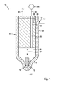
- the Indian Fig. 1 fuel injector 10 shown greatly simplified is designed as a so-called common rail injector, and is used to inject fuel into the combustion chamber, not shown, of an internal combustion engine, in particular a self-igniting internal combustion engine.
- the fuel injector 10 has an essentially made of metal, possibly multi-part design injector housing 11, in which on the combustion chamber of the internal combustion engine side facing at least one, preferably a plurality of injection openings 12 are arranged for injecting the fuel.
- this forms a high-pressure chamber 15, in which a nozzle needle 16 serving as an injection member is arranged in a liftable manner in the direction of the double arrow 17.
- a nozzle needle 16 serving as an injection member is arranged in a liftable manner in the direction of the double arrow 17.
- this forms together with the inner wall of the high-pressure chamber 15 and the injector 11 a sealing seat, so that the injection openings 12 are at least indirectly closed, such that the injection of fuel from the high-pressure chamber 15 in the Combustion chamber of the internal combustion engine is avoided.
- the nozzle needle 16 In the other, not shown, lifted from the sealing seat position of the nozzle needle 16, this releases the injection openings 12 for injecting the fuel into the combustion chamber of the internal combustion engine.
- the movement of the nozzle needle 16, in particular for releasing the injection openings 12, takes place in a manner known per se by means of an actuator, not shown, which can be actuated via a voltage supply line 18 by a control device of the internal combustion engine.
- the actuator may in particular be a magnetic actuator or else a piezoactuator.
- the supply of the high-pressure chamber 15 with fuel under high pressure takes place via a valve disposed within the injector housing 11 or formed in components of the fuel injector 10 Supply bore 19, which in particular eccentrically to the longitudinal axis 21 of the injector 11 in an edge region of the fuel injector 10, at least substantially parallel to the longitudinal axis 21 extends.
- the supply bore 19 is also connected via a fuel connection, not shown, with a fuel line 22, which in turn is coupled to a fuel reservoir 25 (rail).
- a blind hole-shaped recess 24 is formed, so that the wall thickness of the injector 11 is reduced in the region of the recess 24.
- the injector housing 11 may also have a flattening, in the region of which the wall thickness of the injector housing 11 is reduced.
- the flat bottom 26 of the recess 24 forms part of a deformation region 27.
- the injector 11 is arranged for example in operative connection with a branch 28, which in turn opens into the supply hole 19.
- the fuel pressure currently prevailing in the supply bore 19 also acts in the injector housing 11 on the side facing away from the recess 24.
- the wall section 29 of the injector housing 11 acts on the recess 24 facing side as a deformation region 27 in the manner of an elastically deformable membrane, wherein the deformation, which forms as a curvature, the higher the instantaneous fuel pressure in the supply bore 19 or the branch 28 is, the greater.
- the fuel injector 10 For detecting the instantaneous fuel pressure in the branch 28 or in the supply bore 19 and thus also in the high-pressure chamber 15, which is used as an indication of the instantaneous position of the nozzle needle 16 for controlling the nozzle needle 16, the fuel injector 10 has a measuring device 30.
- the measuring device 30 comprises a sensor element 32 designed as a piezo element 31.
- the piezo element 31 is connected to the deformation region 27 via a material connection in the form of an adhesive connection 34. On the side of the piezoelectric element 31 opposite the adhesive joint 34, this is arranged in operative connection with a support device 35.
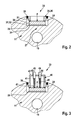
- the support means 35 has a support ring 36, preferably made of metal, which is in operative connection with a partial region of the adhesive surface 34 opposite end face of the piezoelectric element 31, in particular via an annular peripheral outer portion 37, with the interposition of an elastic, preferably also annular intermediate member 38 is arranged with the piezoelectric element 31.
- the support ring 36 is rigidly connected to the (metallic) injector housing 11 via a weld seam 39, which at least partially surrounds its outer circumference and which is preferably designed as a laser weld seam. It is essential that an at least substantially perpendicular to the surface of the piezoelectric element 31 acting axial force F is generated by the rigid connection of the support ring 36 and the support means 35 to the piezoelectric element 31, which also acts on the adhesive connection 34 via the piezoelectric element 31.
- the electrical contacting of the piezoelectric element 31 takes place in a manner known per se, and therefore not shown, on the end face of the piezoelectric element 31 opposite the adhesive joint 34 in the central region of the piezoelectric element 31, i. in the released from the support ring 36 central region of the piezoelectric element 31st
- modified support means 40 differs from the support means 35 by the use of a cup-shaped housing 41 instead of the support ring 36.
- the housing 41 is connected in analogy to the support ring 36 via a welded joint 39 with the injector 11. Due to the cup-shaped design of the housing 41, a media-tight seal of both the sensor element 32, as well as the recess 24 is achieved on the injector 11.
- housing wall 42 of the housing 41 has two openings 43, 44 are formed through which two, the electrical contacting of the piezoelectric element 31 serving contact pins or connector elements 45, 46 protrude.
- the plug elements 45, 46 are sealing in the region of the openings 43, 44 with the housing 11 and rigidly connected.
- a contact element 47, 48 formed by way of example as a compression spring, in particular with their two electrodes serving the electrical contacting of the piezo element 31 (which, for the sake of simplicity not shown in the drawing).
- the deformation region 27 elastically deforms outward as a function of the fuel pressure prevailing in the supply bore 19. This deformation is transmitted via the adhesive connection 34 to the piezoelectric element 31, 31a and there generates, as a function of the deformation or the tensile stresses, electrical voltages which can be used by means of a suitable evaluation circuit, at least indirectly to a position of the nozzle needle 16 in the injector housing 11 close.
- the fuel injector 10 described so far can be modified or modified in many ways without deviating from the idea of the invention, in particular the shape or structure of the piezoelectric element 31, 31a may deviate from the illustrated embodiments.
Landscapes
- Engineering & Computer Science (AREA)
- Chemical & Material Sciences (AREA)
- Analytical Chemistry (AREA)
- Combustion & Propulsion (AREA)
- Mechanical Engineering (AREA)
- General Engineering & Computer Science (AREA)
- Fuel-Injection Apparatus (AREA)
Abstract
Description
- Die Erfindung betrifft einen Kraftstoffinjektor, insbesondere einen Common-Rail-Injektor, nach dem Oberbegriff des Anspruchs 1.
- Ein Kraftstoffinjektor nach dem Oberbegriff des Anspruchs 1 ist aus der nachveröffentlichten
DE 10 2014 209330 A1 der Anmelderin bekannt. Bei dem bekannten Kraftstoffinjektor wird insbesondere zur Erkennung des Zeitpunkts des Schließens der Düsennadel, bei dem diese auf ihren Sitz im Injektorgehäuse auftrifft und dadurch im Injektorgehäuse ausgebildete Einspritzöffnung zumindest mittelbar verschließt, eine Messeinrichtung mit einem Sensorelement verwendet, das im Bereich einer Versorgungsbohrung am Injektorgehäuse angeordnet ist. Die Versorgungsbohrung versorgt einen Hochdruckraum, in dem auch die Düsennadel angeordnet ist, mit unter Hochdruck stehendem Kraftstoff. Insbesondere weist das Injektorgehäuse im Bereich der Messeinrichtung einen Verformungsbereich auf, der in Abhängigkeit des Kraftstoffdrucks in der Versorgungsbohrung elastisch deformierbar ausgebildet ist. Bei einer Druckerhöhung in der Versorgungsbohrung wölbt sich der Verformungsbereich nach außen hin, was mittels des Sensorelements detektierbar ist. Das Sensorelement ist bei dem bekannten Kraftstoffinjektor mittels einer Klebeverbindung mit dem Verformungsbereich verbunden und dazu ausgebildet, in dem Kontaktbereich zum Injektorgehäuse auftretende Dehnungen bzw. Zugspannungen zu erfassen, wobei die Größe bzw. Höhe der Dehnungen in Abhängigkeit von dem Druck in der Versorgungsbohrung ist. Charakteristisch beim angesprochenen Verschließen der Einspritzöffnungen durch die Düsennadel ist es, dass dadurch ein (relativ starker bzw. schneller) Druckanstieg in der Versorgungsleitung stattfindet, da kein Kraftstoff mehr über die Einspritzöffnungen abgegeben wird, wobei der Druckanstieg mittels des Sensorelements erfasst wird. - Während des Betriebs der Brennkraftmaschine ist die Klebeverbindung nicht nur unterschiedlichen Temperaturen ausgesetzt, sondern auch anderen Umwelteinflüssen wie insbesondere Verschmutzungen oder Gasen, die je nach Zusammensetzung die Dauerfestigkeit der Klebeverbindung negativ beeinflussen können.
- Ausgehend von dem dargestellten Stand der Technik liegt der Erfindung die Aufgabe zugrunde, einen Kraftstoffinjektor nach dem Oberbegriff des Anspruchs 1, bei der das Sensorelement mit dem Verformungsbereich über eine Klebeverbindung verbunden ist, derart weiterzubilden, dass eine über die Betriebsdauer des Kraftstoffinjektors zuverlässige Verbindung bzw. Ankopplung des Sensorelements an dem Verformungsbereich mittels der Klebeverbindung erzielt wird.
- Diese Aufgabe wird erfindungsgemäß bei einem Kraftstoffinjektor mit den kennzeichnenden Merkmalen des Anspruchs 1 dadurch gelöst, dass das Sensorelement mittels einer Stützeinrichtung in Richtung des Verformungsbereichs kraftbeaufschlagt ist.
- Mit anderen Worten gesagt bedeutet dies, dass zusätzlich zur Verbindung des Sensorelements über die Klebeverbindung das Sensorelement mittels der angesprochenen Stützeinrichtung derart in Richtung des Verformungsbereichs kraftbeaufschlagt ist, dass selbst bei einem Nachlassen bzw. Versagen der Klebeverbindung über die Stützeinrichtung eine Kontaktierung bzw. Anlage des Sensorelements an dem Verformungsbereich erzielt wird. Vorzugsweise ist die Stützeinrichtung derart in Wirkverbindung mit dem Sensorelement angeordnet, dass mittels der Stützeinrichtung eine Kraftkomponente auf das Sensorelement erzielt wird, die zumindest im Wesentlichen senkrecht zur Sensoroberfläche bzw. zur Klebeverbindung ausgerichtet ist.
- Vorteilhafte Weiterbildungen des erfindungsgemäßen Kraftstoffinjektors sind in den Unteransprüchen angeführt.
- In konstruktiv bevorzugter Ausgestaltung der Stützeinrichtung ist es vorgesehen, dass die Stützeinrichtung mit dem Injektorgehäuse starr verbunden ist. Durch die starre Verbindung der Stützeinrichtung mit dem Injektorgehäuse wird insbesondere die benötigte auf das Sensorelement wirkende Abstützkraft erzeugt.
- Insbesondere kann es vorgesehen sein, dass sich die Stützeinrichtung auf der der Klebeverbindung abgewandten Seite des Sensorelements über ein elastisches Zwischenelement an dem Sensorelement abstützt. Das elastische Zwischenelement bewirkt zum einem eine mechanische Entlastung des Sensorelements bzw. das Vermeiden mechanischer Beschädigungen des Sensorelements sowie andererseits das Aufbringen einer elastischen Vorspannkraft auf das Sensorelement, die insbesondere dazu geeignet ist, eine Deformation des Verformungsbereichs und einer damit verbundenen Bewegung des Sensorelements in Bezug auf die Stützeinrichtung zu ermöglichen bzw. zuzulassen. Dies wiederum verbessert die Auflösung bzw. Genauigkeit der von dem Sensorelement erfassten Deformation des Verformungsbereichs.
- In konstruktiv bevorzugter Umsetzung der Stützeinrichtung weist diese ein vorzugsweise aus Metall bestehendes Gehäuse auf, das mit dem Injektorgehäuse mittels einer Schweißverbindung, vorzugsweise mittels einer Laserschweißnaht, verbunden ist. Eine derartige Verbindung lässt sich fertigungstechnisch relativ einfach in den Fertigungsablauf des Kraftstoffinjektors integrieren und ermöglicht eine sichere und zuverlässige Verbindung des Gehäuses mit dem Injektorgehäuse.
- Ganz besonders bevorzugt ist es, wenn das Sensorelement als Piezoelement ausgebildet ist. Ein derartiges Sensorelement ermöglicht bei relativ geringen Herstellkosten eine sichere und zuverlässige Erfassung von Spannungen in der Oberfläche des Verformungsbereichs und somit einen Rückschluss auf die Deformation des Verformungsbereichs, hervorgerufen durch den Kraftstoffdruck.
- Ganz besonders bevorzugt ist es darüber hinaus, wenn die Stützeinrichtung lediglich in einem Teilbereich des Sensorelements, vorzugsweise in einem radial umlaufenden Teilbereich des Sensorelements, in Wirkverbindung mit dem Sensorelement angeordnet ist. Bei Verwendung eines beispielhaft eine runde Querschnittsfläche aufweisenden Piezoelements als Sensorelement kann es dabei vorgesehen sein, dass die Stützeinrichtung sich über einen ringförmigen Teilbereich, der mit dem Außenumfang des Piezoelements bündig verläuft, an dem Piezoelement abstützt. Dadurch wird der besondere Vorteil erzielt, dass der zentrale Bereich des Sensorelements nicht in Wirkverbindung mit der Stützeinrichtung angeordnet ist. Dies wiederum hat den Vorteil, dass bei einer Deformation des Verformungsbereichs der zentrale Bereich des Verformungsbereichs, der in Überdeckung mit dem Sensorelement bzw. dem Piezoelement angeordnet ist, und der gegenüber einer Ruhelage eine größte Auslenkung erfährt, nicht in Wirkverbindung mit der Stützeinrichtung angeordnet ist. Dies wiederum begünstigt die Genauigkeit bzw. Auflösung des Sensorelements und somit die Genauigkeit der Messergebnisse.
- Insbesondere bei Verwendung eines Piezoelements als Sensorelement wird dieses üblicherweise auf der der Klebeverbindung gegenüberliegenden Stirnfläche elektrisch kontaktiert. Zur Realisierung einer besonders einfachen und zuverlässigen Kontaktierung des Sensorelements ist es vorgesehen, dass an dem Gehäuse starr angeordnete Steckerelemente zur elektrischen Kontaktierung des Sensorelements vorgesehen sind, und dass die Steckerelemente mittels elastisch angeordneter Kontaktelemente in elektrischer Wirkverbindung mit dem Sensorelement, insbesondere mit der der Klebeverbindung gegenüberliegenden Seite des Sensorelements, angeordnet bzw. verbunden sind. Dadurch wird es ermöglicht, dass bei einer Verformung bzw. Bewegung des Sensorelements beispielsweise in dessen zentralem Bereich trotz an dem Gehäuse starr angeordneter elektrischer Steckerelemente die elektrische Kontaktierung mit der Oberfläche des Sensorelements ermöglicht wird, obwohl sich der Abstand zwischen der Oberfläche des Sensorelements zu den starr angeordneten Steckerelementen am Gehäuse ändert.
- Besonders bevorzugt ist es darüber hinaus, wenn das Gehäuse becherförmig ausgebildet ist und das Sensorelement gegenüber der Umgebung mediendicht abdichtet. Dadurch wird insbesondere über die Lebensdauer des Kraftstoffinjektors betrachtet der Zutritt von Medien verhindert, die die Funktionalität des Sensorelements beeinträchtigen, sodass die Zuverlässigkeit der Messeinrichtung erhöht wird.
- Besonders bevorzugt ist die Anordnung des Verformungsbereichs im Bereich der Versorgungsbohrung oder eines mit der Versorgungsbohrung in Wirkverbindung angeordneten Abzweigs. Dies hat den Vorteil, dass die Verbindungsstelle zwischen dem Verformungsbereich und dem Sensorelement in einem relativ brennraumfernen Bereich angeordnet werden kann, in dem insbesondere während des Betriebs der Brennkraftmaschine geringere Temperaturen herrschen als in einem relativ brennraumnahen Bereich des Injektorgehäuses. Dadurch wird insbesondere auch die Verbindung zwischen den angesprochenen Bauteilen thermisch relativ wenig beansprucht. Bei Verwendung eines Abzweigs wird darüber hinaus der besondere Vorteil erzielt, dass trotz der brennraumfernen Anordnung des Sensorelements dieses an nahezu beliebigem Ort in Umfangsrichtung des Injektorgehäuses angeordnet werden kann.
- Bevorzugt ist darüber hinaus eine konstruktive Ausbildung des Verformungsbereichs im Bereich einer sacklochförmigen Vertiefung oder einer Abflachung des Injektorgehäuses. Beide Varianten lassen sich herstellungstechnisch besonders einfach und genau herstellen und ermöglichen darüber hinaus auf relativ einfache Art und Weise die Ausbildung einer ebenen Fläche zur Anbindung des Sensorelements im Bereich der Klebeverbindung.
- Weitere Vorteile, Merkmale und Einzelheiten der Erfindung ergeben sich aus der nachfolgenden Beschreibung bevorzugter Ausführungsbeispiele sowie anhand der Zeichnung.
- Diese zeigt in:
- Fig. 1
- eine stark vereinfachte, teilweise geschnittene Seitenansicht eines erfindungsgemäßen Kraftstoffinjektors mit einer Messeinrichtung zur zumindest mittelbaren Erfassung des Kraftstoffdrucks im Kraftstoffinjektor,
- Fig. 2
- eine erste erfindungsgemäße Stützeinrichtung, die in Wirkverbindung mit einem Sensorelement angeordnet ist, im Bereich der Verbindungsstelle zum Injektorgehäuse in teilweise geschnittener Darstellung und
- Fig. 3
- eine gegenüber
Fig. 2 abgewandelte Stützeinrichtung, ebenfalls in teilweise geschnittener Darstellung. - Gleiche Elemente bzw. Elemente mit gleicher Funktion sind in den Figuren mit den gleichen Bezugsziffern versehen.
- Der in der
Fig. 1 stark vereinfacht dargestellte Kraftstoffinjektor 10 ist als sogenannter Common-Rail-Injektor ausgebildet, und dient dem Einspritzen von Kraftstoff in den nicht gezeigten Brennraum einer Brennkraftmaschine, insbesondere einer selbstzündenden Brennkraftmaschine. - Der Kraftstoffinjektor 10 weist ein im Wesentlichen aus Metall bestehendes, ggf. mehrteilig ausgebildetes Injektorgehäuse 11 auf, in dem auf der dem Brennraum der Brennkraftmaschine zugewandten Seite wenigstens eine, vorzugsweise mehrere Einspritzöffnungen 12 zum Einspritzen des Kraftstoffs eingeordnet sind. Innerhalb des Injektorgehäuses 11 bildet dieses einen Hochdruckraum 15 aus, in dem eine als Einspritzglied dienende Düsennadel 16 in Richtung des Doppelpfeils 17 hubbeweglich angeordnet ist. In der dargestellten, abgesenkten Stellung der Düsennadel 16 bildet diese zusammen mit der Innenwand des Hochdruckraums 15 bzw. des Injektorgehäuses 11 einen Dichtsitz aus, so dass die Einspritzöffnungen 12 zumindest mittelbar verschlossen sind, derart, dass das Einspritzen von Kraftstoff aus dem Hochdruckraum 15 in den Brennraum der Brennkraftmaschine vermieden wird. In der anderen, nicht dargestellten, von dem Dichtsitz abgehobenen Position der Düsennadel 16 gibt diese die Einspritzöffnungen 12 zum Einspritzen des Kraftstoffs in den Brennraum der Brennkraftmaschine frei. Die Bewegung der Düsennadel 16, insbesondere zum Freigeben der Einspritzöffnungen 12, erfolgt auf eine an sich bekannte Art und Weise mittels eines nicht dargestellten Aktuators, der über eine Spannungsversorgungsleitung 18 von einer Steuereinrichtung der Brennkraftmaschine ansteuerbar ist. Bei dem Aktuator kann es sich insbesondere um einen Magnetaktuator oder aber um einen Piezoaktuator handeln.
- Die Versorgung des Hochdruckraums 15 mit unter Hochdruck (Systemdruck) stehendem Kraftstoff erfolgt über eine innerhalb des Injektorgehäuses 11 angeordnete bzw. in Bauteilen des Kraftstoffinjektors 10 ausgebildete Versorgungsbohrung 19, die insbesondere exzentrisch zur Längsachse 21 des Injektorgehäuses 11 in einem Randbereich des Kraftstoffinjektors 10, zumindest im Wesentlichen parallel zur Längsachse 21, verläuft. Die Versorgungsbohrung 19 ist darüber hinaus über einen nicht dargestellten Kraftstoffanschlussstutzen mit einer Kraftstoffleitung 22 verbunden, welche wiederum mit einem Kraftstoffspeicher 25 (Rail) gekoppelt ist.
- In einem von den Einspritzöffnungen 12 bzw. dem Brennraum axial relativ weit beabstandeten Bereich des Injektorgehäuses 11 ist in dessen Außenwand 23 beispielhaft eine sacklochförmige Vertiefung 24 ausgebildet, so dass die Wanddicke des Injektorgehäuses 11 im Bereich der Vertiefung 24 reduziert ist. Ergänzend wird erwähnt, dass anstelle einer sacklochförmigen Vertiefung 24 das Injektorgehäuse 11 auch eine Abflachung aufweisen kann, in deren Bereich die Wanddicke des Injektorgehäuses 11 reduziert ist.
- Der ebene ausgebildete Grund 26 der Vertiefung 24 bildet einen Teil eines Verformungsbereichs 27 aus. Auf der der Vertiefung 24 abgewandten Seite des Injektorgehäuses 11 ist das Injektorgehäuse 11 beispielhaft in Wirkverbindung mit einem Abzweig 28 angeordnet, der wiederum in der Versorgungsbohrung 19 mündet. Dadurch wirkt der in der Versorgungsbohrung 19 augenblicklich herrschende Kraftstoffdruck auch in dem Injektorgehäuse 11 auf der der Vertiefung 24 abgewandten Seite. Dadurch, dass die Wanddicke des Injektorgehäuses 11 im Bereich der Vertiefung 24 reduziert ist, wirkt der Wandabschnitt 29 des Injektorgehäuses 11 auf der der Vertiefung 24 zugewandten Seite als Verformungsbereich 27 in Art einer elastisch verformbaren Membran, wobei die Verformung, welche sich als Wölbung ausbildet, umso größer ist, je höher der augenblickliche Kraftstoffdruck in der Versorgungsbohrung 19 bzw. dem Abzweig 28 ist.
- Zur Detektion des augenblicklichen Kraftstoffdrucks in dem Abzweig 28 bzw. in der Versorgungsbohrung 19 und damit auch in dem Hochdruckraum 15, welcher als Indiz für die augenblickliche Stellung der Düsennadel 16 zur Ansteuerung der Düsennadel 16 verwendet wird, weist der Kraftstoffinjektor 10 eine Messeinrichtung 30 auf. Die Messeinrichtung 30 umfasst ein als Piezoelement 31 ausgebildetes Sensorelement 32.
- Das Piezoelement 31 ist mit dem Verformungsbereich 27 über eine stoffschlüssige Verbindung in Form einer Klebeverbindung 34 verbunden. Auf der der Klebeverbindung 34 gegenüberliegenden Seite des Piezoelements 31 ist dieses in Wirkverbindung mit einer Stützeinrichtung 35 angeordnet. Die Stützeinrichtung 35 weist einen vorzugsweise aus Metall bestehenden Abstützring 36 auf, der in Überdeckung mit einem Teilbereich der der Klebeverbindung 34 gegenüberliegenden Stirnfläche des Piezoelements 31, insbesondere über einen ringförmig umlaufenden äußeren Teilbereich 37, unter Zwischenlage eines elastischen, vorzugsweise ebenfalls ringförmigen Zwischenelements 38 in Wirkverbindung mit dem Piezoelement 31 angeordnet ist. Der Abstützring 36 ist über eine an seinem Außenumfang zumindest teilweise umlaufende Schweißnaht 39, die vorzugsweise als Laserschweißnaht ausgebildet ist, mit dem (metallischen) Injektorgehäuse 11 starr verbunden. Wesentlich dabei ist, dass durch die starre Verbindung des Abstützrings 36 bzw. der Stützeinrichtung 35 auf das Piezoelement 31 eine zumindest im Wesentlichen senkrecht zur Oberfläche des Piezoelements 31 wirkende Axialkraft F erzeugt wird, die über das Piezoelement 31 auch auf die Klebeverbindung 34 wirkt.
- Die elektrische Kontaktierung des Piezoelements 31 erfolgt in an sich bekannter, und daher nicht dargestellter Art und Weise auf der der Klebeverbindung 34 gegenüberliegenden Stirnfläche des Piezoelements 31 in dem zentralen Bereich des Piezoelements 31, d.h. in dem von dem Abstützring 36 freigelassenen zentralen Bereich des Piezoelements 31.
- Die in der
Fig. 3 dargestellte abgewandelte Stützeinrichtung 40 unterscheidet sich von der Stützeinrichtung 35 durch die Verwendung eines becherförmigen Gehäuses 41 anstatt des Abstützrings 36. Das Gehäuse 41 ist in Analogie zu dem Abstützring 36 über eine Schweißverbindung 39 mit dem Injektorgehäuse 11 verbunden. Durch die becherförmige Ausbildung des Gehäuses 41 wird eine mediendichte Dichtung sowohl des Sensorelements 32, als auch der Vertiefung 24 am Injektorgehäuse 11 erzielt. An der dem Piezoelement 31 abgewandten Gehäusewand 42 des Gehäuses 41 sind zwei Durchbrüche 43, 44 ausgebildet, durch die zwei, der elektrischen Kontaktierung des Piezoelements 31 dienende Kontaktstifte bzw. Steckerelemente 45, 46 hindurchragen. Die Steckerelemente 45, 46 sind im Bereich der Durchbrüche 43, 44 mit dem Gehäuse 11 dichtend und starr verbunden. Auf der dem Piezoelement 31 zugewandten Seite der Steckerelemente 45, 46 sind diese über eine beispielhaft als Druckfeder ausgebildete Kontaktelemente 47, 48 mit der Oberfläche des Piezoelements 31 verbunden, insbesondere mit deren beiden, der elektrischen Kontaktierung des Piezoelements 31 dienenden Elektroden (die der Einfachheit halber in der Zeichnung nicht dargestellt sind). - Beim Betrieb des Kraftstoffinjektors 10 verformt sich der Verformungsbereich 27 in Abhängigkeit des in der Versorgungsbohrung 19 herrschenden Kraftstoffdrucks elastisch nach außen. Diese Verformung überträgt sich über die Klebeverbindung 34 auf das Piezoelement 31, 31a und erzeugt dort in Abhängigkeit der Verformung bzw. der Zugspannungen elektrische Spannungen, die mittels einer geeigneten Auswerteschaltung dazu verwendet werden können, zumindest mittelbar auf eine Stellung der Düsennadel 16 in dem Injektorgehäuse 11 zu schließen.
- Der soweit beschriebene Kraftstoffinjektor 10 kann in vielfältiger Art und Weise abgewandelt bzw. modifiziert werden, ohne vom Erfindungsgedanken abzuweichen, so kann insbesondere die Form oder der Aufbau des Piezoelements 31, 31a von den dargestellten Ausführungsformen abweichen.
Claims (10)
- Kraftstoffinjektor (10), insbesondere Common-Rail-Injektor, mit einem Injektorgehäuse (11), in dem ein Hochdruckraum (15) ausgebildet ist, der über eine im Injektorgehäuse (11) angeordnete Versorgungsbohrung (19) mit unter Druck stehendem Kraftstoff versorgbar ist, mit wenigstens einer zumindest mittelbar mit dem Hochdruckraum (15) verbundenen, im Injektorgehäuse (11) ausgebildeten Einspritzöffnung (12) zum Einspritzen von Kraftstoff in den Brennraum einer Brennkraftmaschine, mit einem die wenigstens eine Einspritzöffnung (12) freigebenden oder verschließenden Einspritzglied (16), und mit einer Messeinrichtung (30) zur zumindest mittelbaren Erfassung des Drucks im Hochdruckraum (15) oder der Versorgungsbohrung (19), wobei die Messeinrichtung (35) dazu ausgebildet ist, eine elastische Verformung eines zumindest mittelbar mit der Versorgungsbohrung (19) oder dem Hochdruckraum (15) in Wirkverbindung angeordneten Verformungsbereichs (27) zu erfassen, und wobei die Messeinrichtung (30) ein Sensorelement (32) aufweist, das mit der Oberfläche des Verformungsbereichs (27) über eine Klebeverbindung (34) verbunden ist,
dadurch gekennzeichnet,
dass das Sensorelement (32) mittels einer Stützeinrichtung (35; 40) in Richtung des Verformungsbereichs (27) kraftbeaufschlagt ist. - Kraftstoffinjektor nach Anspruch 1,
dadurch gekennzeichnet,
dass die Stützeinrichtung (35; 40) mit dem Injektorgehäuse (11) starr verbunden ist. - Kraftstoffinjektor nach Anspruch 1 oder 2,
dadurch gekennzeichnet,
dass sich die Stützeinrichtung (35; 40) auf der der Klebeverbindung (34) abgewandten Seite des Sensorelements (32) über ein elastisches Zwischenelement (38) an dem Sensorelement (32) abstützt. - Kraftstoffinjektor nach Anspruch 3,
dadurch gekennzeichnet,
dass die Stützeinrichtung (35; 40) ein vorzugsweise aus Metall bestehendes Gehäuse (41) aufweist, das mit dem Injektorgehäuse (11) mittels einer Schweißverbindung (39), vorzugsweise mittels einer Laserschweißnaht, verbunden ist. - Kraftstoffinjektor nach einem der Ansprüche 1 bis 4,
dadurch gekennzeichnet,
dass das Sensorelement (32) als Piezoelement (31, 31 a) ausgebildet ist. - Kraftstoffinjektor nach einem der Ansprüche 1 bis 5,
dadurch gekennzeichnet,
dass die Stützeinrichtung (35; 40) lediglich in einem Teilbereich (37) des Sensorelements (32), vorzugsweise in einem randseitig umlaufenden Teilbereich (37) des Sensorelements (32), in Wirkverbindung mit dem Sensorelement (32) angeordnet ist. - Kraftstoffinjektor nach einem der Ansprüche 4 bis 6,
dadurch gekennzeichnet,
dass an dem Gehäuse (41) starr angeordnete Steckerelemente (45, 46) zur elektrischen Kontaktierung des Sensorelements (32) vorgesehen sind, und dass die Steckerelemente (45, 46) mittels elastisch angeordneter Kontaktelemente (47, 48) in elektrischer Wirkverbindung mit dem Sensorelement (32), insbesondere mit der der Klebeverbindung (34) gegenüberliegenden Seite des Sensorelements (32), angeordnet sind. - Kraftstoffinjektor nach einem der Ansprüche 4 bis 7,
dadurch gekennzeichnet,
dass das Gehäuse (41) becherförmig ausgebildet ist und das Sensorelement (32) gegenüber der Umgebung mediendicht abdichtet. - Kraftstoffinjektor nach einem der Ansprüche 1 bis 8,
dadurch gekennzeichnet,
dass der Verformungsbereich (27) im Bereich einer sacklochförmigen Vertiefung (24) oder einer Abflachung des Injektorgehäuses (11) angeordnet ist. - Kraftstoffinjektor nach einem der Ansprüche 1 bis 9,
dadurch gekennzeichnet,
dass der Verformungsbereich (27) im Bereich der Versorgungsbohrung (19) oder eines mit der Versorgungsbohrung (19) in Wirkverbindung angeordneten Abzweigs (28) angeordnet ist.
Applications Claiming Priority (1)
| Application Number | Priority Date | Filing Date | Title |
|---|---|---|---|
| DE102014222811.5A DE102014222811A1 (de) | 2014-11-07 | 2014-11-07 | Kraftstoffinjektor |
Publications (2)
| Publication Number | Publication Date |
|---|---|
| EP3018337A1 true EP3018337A1 (de) | 2016-05-11 |
| EP3018337B1 EP3018337B1 (de) | 2018-03-14 |
Family
ID=54359795
Family Applications (1)
| Application Number | Title | Priority Date | Filing Date |
|---|---|---|---|
| EP15190124.6A Active EP3018337B1 (de) | 2014-11-07 | 2015-10-16 | Kraftstoffinjektor |
Country Status (2)
| Country | Link |
|---|---|
| EP (1) | EP3018337B1 (de) |
| DE (1) | DE102014222811A1 (de) |
Cited By (3)
| Publication number | Priority date | Publication date | Assignee | Title |
|---|---|---|---|---|
| EP3088729A1 (de) * | 2015-04-30 | 2016-11-02 | Robert Bosch Gmbh | Kraftstoffinjektor sowie vorrichtung und verfahren zur montage einer messeinrichtung |
| EP3222844A1 (de) * | 2016-03-23 | 2017-09-27 | Robert Bosch GmbH | Kraftstoffinjektor |
| EP3076001B1 (de) * | 2015-04-02 | 2020-07-08 | Robert Bosch GmbH | Kraftstoffinjektor |
Families Citing this family (6)
| Publication number | Priority date | Publication date | Assignee | Title |
|---|---|---|---|---|
| DE102015206032A1 (de) | 2015-04-02 | 2016-10-06 | Robert Bosch Gmbh | Kraftstoffinjektor und Verfahren zum Herstellen eines Kraftstoffinjektors |
| DE102015208069A1 (de) | 2015-04-30 | 2016-11-03 | Robert Bosch Gmbh | Kraftstoffinjektor |
| DE102015223902A1 (de) | 2015-12-01 | 2017-06-01 | Robert Bosch Gmbh | Sensorvorrichtung und Kraftstoffinjektor mit einer Sensorvorrichtung |
| DE102015225047A1 (de) | 2015-12-14 | 2017-06-14 | Robert Bosch Gmbh | Sensorvorrichtung und Kraftstoffinjektor mit einer Sensorvorrichtung |
| DE102017209560A1 (de) | 2017-06-07 | 2018-12-13 | Robert Bosch Gmbh | Kraftstoffinjektor |
| DE102019200232A1 (de) * | 2019-01-10 | 2020-07-16 | Robert Bosch Gmbh | Kraftstoffinjektor |
Citations (3)
| Publication number | Priority date | Publication date | Assignee | Title |
|---|---|---|---|---|
| EP2105602A2 (de) * | 2008-03-28 | 2009-09-30 | Denso Corporation | Kraftstoffdrucksensor/Sensormontageanordnung, Kraftstoffeinspritzvorrichtung und Drucksensorvorrichtung |
| EP2918819A1 (de) * | 2014-03-13 | 2015-09-16 | Robert Bosch Gmbh | Kraftstoffinjektor, insbesondere Common-Rail-Injektor |
| EP2918820A1 (de) * | 2014-03-14 | 2015-09-16 | Robert Bosch Gmbh | Kraftstoffinjektor, insbesondere Common-Rail-Injektor |
Family Cites Families (1)
| Publication number | Priority date | Publication date | Assignee | Title |
|---|---|---|---|---|
| DE102014209330A1 (de) | 2014-05-16 | 2015-11-19 | Robert Bosch Gmbh | Vorrichtung zur Erfassung des Kraftstoffdrucks für einen Kraftstoffinjektor, Kraftstoffinjektor sowie Kraftstoffzuführleitung zu einem Kraftstoffinjektor |
-
2014
- 2014-11-07 DE DE102014222811.5A patent/DE102014222811A1/de not_active Withdrawn
-
2015
- 2015-10-16 EP EP15190124.6A patent/EP3018337B1/de active Active
Patent Citations (3)
| Publication number | Priority date | Publication date | Assignee | Title |
|---|---|---|---|---|
| EP2105602A2 (de) * | 2008-03-28 | 2009-09-30 | Denso Corporation | Kraftstoffdrucksensor/Sensormontageanordnung, Kraftstoffeinspritzvorrichtung und Drucksensorvorrichtung |
| EP2918819A1 (de) * | 2014-03-13 | 2015-09-16 | Robert Bosch Gmbh | Kraftstoffinjektor, insbesondere Common-Rail-Injektor |
| EP2918820A1 (de) * | 2014-03-14 | 2015-09-16 | Robert Bosch Gmbh | Kraftstoffinjektor, insbesondere Common-Rail-Injektor |
Cited By (3)
| Publication number | Priority date | Publication date | Assignee | Title |
|---|---|---|---|---|
| EP3076001B1 (de) * | 2015-04-02 | 2020-07-08 | Robert Bosch GmbH | Kraftstoffinjektor |
| EP3088729A1 (de) * | 2015-04-30 | 2016-11-02 | Robert Bosch Gmbh | Kraftstoffinjektor sowie vorrichtung und verfahren zur montage einer messeinrichtung |
| EP3222844A1 (de) * | 2016-03-23 | 2017-09-27 | Robert Bosch GmbH | Kraftstoffinjektor |
Also Published As
| Publication number | Publication date |
|---|---|
| EP3018337B1 (de) | 2018-03-14 |
| DE102014222811A1 (de) | 2016-05-12 |
Similar Documents
| Publication | Publication Date | Title |
|---|---|---|
| EP3018337B1 (de) | Kraftstoffinjektor | |
| EP3076002B1 (de) | Kraftstoffinjektor | |
| EP3088729B1 (de) | Kraftstoffinjektor sowie vorrichtung und verfahren zur montage einer messeinrichtung | |
| EP3179090B1 (de) | Kraftstoffinjektor | |
| EP3023627B1 (de) | Kraftstoffinjektor | |
| EP3076001B1 (de) | Kraftstoffinjektor | |
| EP3018336B1 (de) | Kraftstoffinjektor | |
| EP3023758B1 (de) | Kraftstoffinjektor | |
| EP3908743B1 (de) | Kraftstoffinjektor | |
| EP3026253B1 (de) | Kraftstoffinjektor | |
| DE102018200357A1 (de) | Ventil zum Zumessen eines Fluids, insbesondere Brennstoffeinspritzventil | |
| EP3088723B1 (de) | Kraftstoffinjektor | |
| DE102015208488A1 (de) | Kraftstoffinjektor sowie Vorrichtung und Verfahren zur Montage einer Messeinrichtung | |
| DE102015211186A1 (de) | Kraftstoffinjektor | |
| EP3076005B1 (de) | Kraftstoffinjektor und verfahren zum herstellen eines kraftstoffinjektors | |
| EP3034854B1 (de) | Kraftstoffinjektor und verfahren zur erkennung zumindest des schliesszeitpunkts eines einspritzglieds | |
| DE102018208318A1 (de) | Kraftstoffinjektor | |
| EP3176556B1 (de) | Sensorvorrichtung und kraftstoffinjektor mit einer sensorvorrichtung | |
| EP3181890A1 (de) | Sensorvorrichtung und kraftstoffinjektor mit einer sensorvorrichtung | |
| EP3018338A1 (de) | Kraftstoffinjektor und verfahren zum herstellen eines kraftstoffinjektors | |
| EP3088724A1 (de) | Kraftstoffinjektor | |
| DE102015224683A1 (de) | Kraftstoffinjektor | |
| EP3109453A1 (de) | Kraftstoffinjektor | |
| EP3112662A1 (de) | Kraftstoffinjektor |
Legal Events
| Date | Code | Title | Description |
|---|---|---|---|
| PUAI | Public reference made under article 153(3) epc to a published international application that has entered the european phase |
Free format text: ORIGINAL CODE: 0009012 |
|
| AK | Designated contracting states |
Kind code of ref document: A1 Designated state(s): AL AT BE BG CH CY CZ DE DK EE ES FI FR GB GR HR HU IE IS IT LI LT LU LV MC MK MT NL NO PL PT RO RS SE SI SK SM TR |
|
| AX | Request for extension of the european patent |
Extension state: BA ME |
|
| 17P | Request for examination filed |
Effective date: 20161111 |
|
| RBV | Designated contracting states (corrected) |
Designated state(s): AL AT BE BG CH CY CZ DE DK EE ES FI FR GB GR HR HU IE IS IT LI LT LU LV MC MK MT NL NO PL PT RO RS SE SI SK SM TR |
|
| GRAP | Despatch of communication of intention to grant a patent |
Free format text: ORIGINAL CODE: EPIDOSNIGR1 |
|
| INTG | Intention to grant announced |
Effective date: 20171214 |
|
| GRAS | Grant fee paid |
Free format text: ORIGINAL CODE: EPIDOSNIGR3 |
|
| GRAA | (expected) grant |
Free format text: ORIGINAL CODE: 0009210 |
|
| AK | Designated contracting states |
Kind code of ref document: B1 Designated state(s): AL AT BE BG CH CY CZ DE DK EE ES FI FR GB GR HR HU IE IS IT LI LT LU LV MC MK MT NL NO PL PT RO RS SE SI SK SM TR |
|
| REG | Reference to a national code |
Ref country code: GB Ref legal event code: FG4D Free format text: NOT ENGLISH |
|
| REG | Reference to a national code |
Ref country code: CH Ref legal event code: EP Ref country code: AT Ref legal event code: REF Ref document number: 979142 Country of ref document: AT Kind code of ref document: T Effective date: 20180315 |
|
| REG | Reference to a national code |
Ref country code: IE Ref legal event code: FG4D Free format text: LANGUAGE OF EP DOCUMENT: GERMAN |
|
| REG | Reference to a national code |
Ref country code: DE Ref legal event code: R096 Ref document number: 502015003368 Country of ref document: DE |
|
| REG | Reference to a national code |
Ref country code: NL Ref legal event code: MP Effective date: 20180314 |
|
| REG | Reference to a national code |
Ref country code: LT Ref legal event code: MG4D |
|
| PG25 | Lapsed in a contracting state [announced via postgrant information from national office to epo] |
Ref country code: NO Free format text: LAPSE BECAUSE OF FAILURE TO SUBMIT A TRANSLATION OF THE DESCRIPTION OR TO PAY THE FEE WITHIN THE PRESCRIBED TIME-LIMIT Effective date: 20180614 Ref country code: HR Free format text: LAPSE BECAUSE OF FAILURE TO SUBMIT A TRANSLATION OF THE DESCRIPTION OR TO PAY THE FEE WITHIN THE PRESCRIBED TIME-LIMIT Effective date: 20180314 Ref country code: CY Free format text: LAPSE BECAUSE OF FAILURE TO SUBMIT A TRANSLATION OF THE DESCRIPTION OR TO PAY THE FEE WITHIN THE PRESCRIBED TIME-LIMIT Effective date: 20180314 Ref country code: LT Free format text: LAPSE BECAUSE OF FAILURE TO SUBMIT A TRANSLATION OF THE DESCRIPTION OR TO PAY THE FEE WITHIN THE PRESCRIBED TIME-LIMIT Effective date: 20180314 Ref country code: FI Free format text: LAPSE BECAUSE OF FAILURE TO SUBMIT A TRANSLATION OF THE DESCRIPTION OR TO PAY THE FEE WITHIN THE PRESCRIBED TIME-LIMIT Effective date: 20180314 |
|
| PG25 | Lapsed in a contracting state [announced via postgrant information from national office to epo] |
Ref country code: BG Free format text: LAPSE BECAUSE OF FAILURE TO SUBMIT A TRANSLATION OF THE DESCRIPTION OR TO PAY THE FEE WITHIN THE PRESCRIBED TIME-LIMIT Effective date: 20180614 Ref country code: GR Free format text: LAPSE BECAUSE OF FAILURE TO SUBMIT A TRANSLATION OF THE DESCRIPTION OR TO PAY THE FEE WITHIN THE PRESCRIBED TIME-LIMIT Effective date: 20180615 Ref country code: LV Free format text: LAPSE BECAUSE OF FAILURE TO SUBMIT A TRANSLATION OF THE DESCRIPTION OR TO PAY THE FEE WITHIN THE PRESCRIBED TIME-LIMIT Effective date: 20180314 Ref country code: SE Free format text: LAPSE BECAUSE OF FAILURE TO SUBMIT A TRANSLATION OF THE DESCRIPTION OR TO PAY THE FEE WITHIN THE PRESCRIBED TIME-LIMIT Effective date: 20180314 Ref country code: RS Free format text: LAPSE BECAUSE OF FAILURE TO SUBMIT A TRANSLATION OF THE DESCRIPTION OR TO PAY THE FEE WITHIN THE PRESCRIBED TIME-LIMIT Effective date: 20180314 |
|
| PG25 | Lapsed in a contracting state [announced via postgrant information from national office to epo] |
Ref country code: MT Free format text: LAPSE BECAUSE OF FAILURE TO SUBMIT A TRANSLATION OF THE DESCRIPTION OR TO PAY THE FEE WITHIN THE PRESCRIBED TIME-LIMIT Effective date: 20180314 |
|
| REG | Reference to a national code |
Ref country code: FR Ref legal event code: PLFP Year of fee payment: 4 |
|
| PG25 | Lapsed in a contracting state [announced via postgrant information from national office to epo] |
Ref country code: EE Free format text: LAPSE BECAUSE OF FAILURE TO SUBMIT A TRANSLATION OF THE DESCRIPTION OR TO PAY THE FEE WITHIN THE PRESCRIBED TIME-LIMIT Effective date: 20180314 Ref country code: PL Free format text: LAPSE BECAUSE OF FAILURE TO SUBMIT A TRANSLATION OF THE DESCRIPTION OR TO PAY THE FEE WITHIN THE PRESCRIBED TIME-LIMIT Effective date: 20180314 Ref country code: AL Free format text: LAPSE BECAUSE OF FAILURE TO SUBMIT A TRANSLATION OF THE DESCRIPTION OR TO PAY THE FEE WITHIN THE PRESCRIBED TIME-LIMIT Effective date: 20180314 Ref country code: NL Free format text: LAPSE BECAUSE OF FAILURE TO SUBMIT A TRANSLATION OF THE DESCRIPTION OR TO PAY THE FEE WITHIN THE PRESCRIBED TIME-LIMIT Effective date: 20180314 Ref country code: RO Free format text: LAPSE BECAUSE OF FAILURE TO SUBMIT A TRANSLATION OF THE DESCRIPTION OR TO PAY THE FEE WITHIN THE PRESCRIBED TIME-LIMIT Effective date: 20180314 Ref country code: ES Free format text: LAPSE BECAUSE OF FAILURE TO SUBMIT A TRANSLATION OF THE DESCRIPTION OR TO PAY THE FEE WITHIN THE PRESCRIBED TIME-LIMIT Effective date: 20180314 |
|
| PG25 | Lapsed in a contracting state [announced via postgrant information from national office to epo] |
Ref country code: CZ Free format text: LAPSE BECAUSE OF FAILURE TO SUBMIT A TRANSLATION OF THE DESCRIPTION OR TO PAY THE FEE WITHIN THE PRESCRIBED TIME-LIMIT Effective date: 20180314 Ref country code: SK Free format text: LAPSE BECAUSE OF FAILURE TO SUBMIT A TRANSLATION OF THE DESCRIPTION OR TO PAY THE FEE WITHIN THE PRESCRIBED TIME-LIMIT Effective date: 20180314 Ref country code: SM Free format text: LAPSE BECAUSE OF FAILURE TO SUBMIT A TRANSLATION OF THE DESCRIPTION OR TO PAY THE FEE WITHIN THE PRESCRIBED TIME-LIMIT Effective date: 20180314 |
|
| REG | Reference to a national code |
Ref country code: DE Ref legal event code: R097 Ref document number: 502015003368 Country of ref document: DE |
|
| PG25 | Lapsed in a contracting state [announced via postgrant information from national office to epo] |
Ref country code: PT Free format text: LAPSE BECAUSE OF FAILURE TO SUBMIT A TRANSLATION OF THE DESCRIPTION OR TO PAY THE FEE WITHIN THE PRESCRIBED TIME-LIMIT Effective date: 20180716 |
|
| PLBE | No opposition filed within time limit |
Free format text: ORIGINAL CODE: 0009261 |
|
| STAA | Information on the status of an ep patent application or granted ep patent |
Free format text: STATUS: NO OPPOSITION FILED WITHIN TIME LIMIT |
|
| PG25 | Lapsed in a contracting state [announced via postgrant information from national office to epo] |
Ref country code: DK Free format text: LAPSE BECAUSE OF FAILURE TO SUBMIT A TRANSLATION OF THE DESCRIPTION OR TO PAY THE FEE WITHIN THE PRESCRIBED TIME-LIMIT Effective date: 20180314 |
|
| 26N | No opposition filed |
Effective date: 20181217 |
|
| PG25 | Lapsed in a contracting state [announced via postgrant information from national office to epo] |
Ref country code: SI Free format text: LAPSE BECAUSE OF FAILURE TO SUBMIT A TRANSLATION OF THE DESCRIPTION OR TO PAY THE FEE WITHIN THE PRESCRIBED TIME-LIMIT Effective date: 20180314 |
|
| REG | Reference to a national code |
Ref country code: CH Ref legal event code: PL |
|
| REG | Reference to a national code |
Ref country code: BE Ref legal event code: MM Effective date: 20181031 |
|
| PG25 | Lapsed in a contracting state [announced via postgrant information from national office to epo] |
Ref country code: MC Free format text: LAPSE BECAUSE OF FAILURE TO SUBMIT A TRANSLATION OF THE DESCRIPTION OR TO PAY THE FEE WITHIN THE PRESCRIBED TIME-LIMIT Effective date: 20180314 Ref country code: LU Free format text: LAPSE BECAUSE OF NON-PAYMENT OF DUE FEES Effective date: 20181016 |
|
| REG | Reference to a national code |
Ref country code: IE Ref legal event code: MM4A |
|
| PG25 | Lapsed in a contracting state [announced via postgrant information from national office to epo] |
Ref country code: LI Free format text: LAPSE BECAUSE OF NON-PAYMENT OF DUE FEES Effective date: 20181031 Ref country code: CH Free format text: LAPSE BECAUSE OF NON-PAYMENT OF DUE FEES Effective date: 20181031 Ref country code: BE Free format text: LAPSE BECAUSE OF NON-PAYMENT OF DUE FEES Effective date: 20181031 |
|
| PG25 | Lapsed in a contracting state [announced via postgrant information from national office to epo] |
Ref country code: IE Free format text: LAPSE BECAUSE OF NON-PAYMENT OF DUE FEES Effective date: 20181016 |
|
| PG25 | Lapsed in a contracting state [announced via postgrant information from national office to epo] |
Ref country code: TR Free format text: LAPSE BECAUSE OF FAILURE TO SUBMIT A TRANSLATION OF THE DESCRIPTION OR TO PAY THE FEE WITHIN THE PRESCRIBED TIME-LIMIT Effective date: 20180314 |
|
| PG25 | Lapsed in a contracting state [announced via postgrant information from national office to epo] |
Ref country code: MK Free format text: LAPSE BECAUSE OF NON-PAYMENT OF DUE FEES Effective date: 20180314 Ref country code: HU Free format text: LAPSE BECAUSE OF FAILURE TO SUBMIT A TRANSLATION OF THE DESCRIPTION OR TO PAY THE FEE WITHIN THE PRESCRIBED TIME-LIMIT; INVALID AB INITIO Effective date: 20151016 |
|
| PG25 | Lapsed in a contracting state [announced via postgrant information from national office to epo] |
Ref country code: IS Free format text: LAPSE BECAUSE OF FAILURE TO SUBMIT A TRANSLATION OF THE DESCRIPTION OR TO PAY THE FEE WITHIN THE PRESCRIBED TIME-LIMIT Effective date: 20180714 |
|
| GBPC | Gb: european patent ceased through non-payment of renewal fee |
Effective date: 20191016 |
|
| PG25 | Lapsed in a contracting state [announced via postgrant information from national office to epo] |
Ref country code: GB Free format text: LAPSE BECAUSE OF NON-PAYMENT OF DUE FEES Effective date: 20191016 |
|
| REG | Reference to a national code |
Ref country code: AT Ref legal event code: MM01 Ref document number: 979142 Country of ref document: AT Kind code of ref document: T Effective date: 20201016 |
|
| PG25 | Lapsed in a contracting state [announced via postgrant information from national office to epo] |
Ref country code: AT Free format text: LAPSE BECAUSE OF NON-PAYMENT OF DUE FEES Effective date: 20201016 |
|
| PGFP | Annual fee paid to national office [announced via postgrant information from national office to epo] |
Ref country code: DE Payment date: 20251209 Year of fee payment: 11 |
|
| PGFP | Annual fee paid to national office [announced via postgrant information from national office to epo] |
Ref country code: IT Payment date: 20251031 Year of fee payment: 11 |
|
| PGFP | Annual fee paid to national office [announced via postgrant information from national office to epo] |
Ref country code: FR Payment date: 20251024 Year of fee payment: 11 |