EP3018190A1 - Verfahren zur Herstellung von methanreichem Gas - Google Patents
Verfahren zur Herstellung von methanreichem Gas Download PDFInfo
- Publication number
- EP3018190A1 EP3018190A1 EP14191663.5A EP14191663A EP3018190A1 EP 3018190 A1 EP3018190 A1 EP 3018190A1 EP 14191663 A EP14191663 A EP 14191663A EP 3018190 A1 EP3018190 A1 EP 3018190A1
- Authority
- EP
- European Patent Office
- Prior art keywords
- gas
- methanation
- methane
- reactor
- feed
- Prior art date
- Legal status (The legal status is an assumption and is not a legal conclusion. Google has not performed a legal analysis and makes no representation as to the accuracy of the status listed.)
- Withdrawn
Links
- VNWKTOKETHGBQD-UHFFFAOYSA-N methane Chemical compound C VNWKTOKETHGBQD-UHFFFAOYSA-N 0.000 title claims abstract description 248
- 238000000034 method Methods 0.000 title claims abstract description 64
- 238000004519 manufacturing process Methods 0.000 title claims abstract description 12
- 239000007789 gas Substances 0.000 claims abstract description 311
- 239000003054 catalyst Substances 0.000 claims abstract description 56
- 238000004064 recycling Methods 0.000 claims abstract description 30
- CURLTUGMZLYLDI-UHFFFAOYSA-N Carbon dioxide Chemical compound O=C=O CURLTUGMZLYLDI-UHFFFAOYSA-N 0.000 claims abstract description 29
- XLYOFNOQVPJJNP-UHFFFAOYSA-N water Substances O XLYOFNOQVPJJNP-UHFFFAOYSA-N 0.000 claims abstract description 26
- UGFAIRIUMAVXCW-UHFFFAOYSA-N Carbon monoxide Chemical compound [O+]#[C-] UGFAIRIUMAVXCW-UHFFFAOYSA-N 0.000 claims abstract description 20
- 229910002092 carbon dioxide Inorganic materials 0.000 claims abstract description 16
- 229910002090 carbon oxide Inorganic materials 0.000 claims abstract description 14
- 229910002091 carbon monoxide Inorganic materials 0.000 claims abstract description 11
- 229910052739 hydrogen Inorganic materials 0.000 claims abstract description 10
- 239000001257 hydrogen Substances 0.000 claims abstract description 10
- 239000001569 carbon dioxide Substances 0.000 claims abstract description 9
- UFHFLCQGNIYNRP-UHFFFAOYSA-N Hydrogen Chemical compound [H][H] UFHFLCQGNIYNRP-UHFFFAOYSA-N 0.000 claims abstract description 6
- 230000015572 biosynthetic process Effects 0.000 claims description 54
- 238000003786 synthesis reaction Methods 0.000 claims description 43
- NINIDFKCEFEMDL-UHFFFAOYSA-N Sulfur Chemical compound [S] NINIDFKCEFEMDL-UHFFFAOYSA-N 0.000 claims description 22
- 229910052717 sulfur Inorganic materials 0.000 claims description 22
- 239000011593 sulfur Substances 0.000 claims description 22
- 229930195733 hydrocarbon Natural products 0.000 claims description 13
- 150000002430 hydrocarbons Chemical class 0.000 claims description 13
- 238000011144 upstream manufacturing Methods 0.000 claims description 9
- 239000000571 coke Substances 0.000 claims description 8
- 239000003245 coal Substances 0.000 claims description 6
- 239000000470 constituent Substances 0.000 claims description 6
- PXHVJJICTQNCMI-UHFFFAOYSA-N Nickel Chemical compound [Ni] PXHVJJICTQNCMI-UHFFFAOYSA-N 0.000 claims description 5
- 239000003575 carbonaceous material Substances 0.000 claims description 5
- 238000000746 purification Methods 0.000 claims description 5
- 239000002028 Biomass Substances 0.000 claims description 4
- -1 calcium aluminates Chemical class 0.000 claims description 4
- 150000002431 hydrogen Chemical class 0.000 claims description 4
- 239000002006 petroleum coke Substances 0.000 claims description 4
- 229910052759 nickel Inorganic materials 0.000 claims description 3
- 239000002699 waste material Substances 0.000 claims description 3
- 229910020068 MgAl Inorganic materials 0.000 claims description 2
- MCMNRKCIXSYSNV-UHFFFAOYSA-N ZrO2 Inorganic materials O=[Zr]=O MCMNRKCIXSYSNV-UHFFFAOYSA-N 0.000 claims description 2
- PNEYBMLMFCGWSK-UHFFFAOYSA-N aluminium oxide Inorganic materials [O-2].[O-2].[O-2].[Al+3].[Al+3] PNEYBMLMFCGWSK-UHFFFAOYSA-N 0.000 claims description 2
- 239000011575 calcium Substances 0.000 claims description 2
- 229910052791 calcium Inorganic materials 0.000 claims description 2
- 238000009833 condensation Methods 0.000 claims description 2
- 230000005494 condensation Effects 0.000 claims description 2
- 239000003921 oil Substances 0.000 claims description 2
- 229910052596 spinel Inorganic materials 0.000 claims description 2
- 239000011029 spinel Substances 0.000 claims description 2
- OKTJSMMVPCPJKN-UHFFFAOYSA-N Carbon Chemical compound [C] OKTJSMMVPCPJKN-UHFFFAOYSA-N 0.000 description 30
- 229910052799 carbon Inorganic materials 0.000 description 29
- 239000000047 product Substances 0.000 description 21
- 239000000203 mixture Substances 0.000 description 18
- 238000006243 chemical reaction Methods 0.000 description 14
- OTMSDBZUPAUEDD-UHFFFAOYSA-N Ethane Chemical compound CC OTMSDBZUPAUEDD-UHFFFAOYSA-N 0.000 description 7
- 238000001816 cooling Methods 0.000 description 7
- ATUOYWHBWRKTHZ-UHFFFAOYSA-N Propane Chemical compound CCC ATUOYWHBWRKTHZ-UHFFFAOYSA-N 0.000 description 5
- 238000010438 heat treatment Methods 0.000 description 4
- 238000004364 calculation method Methods 0.000 description 3
- 239000012467 final product Substances 0.000 description 3
- 239000003345 natural gas Substances 0.000 description 3
- 239000004215 Carbon black (E152) Substances 0.000 description 2
- RWSOTUBLDIXVET-UHFFFAOYSA-N Dihydrogen sulfide Chemical compound S RWSOTUBLDIXVET-UHFFFAOYSA-N 0.000 description 2
- YTPLMLYBLZKORZ-UHFFFAOYSA-N Thiophene Chemical compound C=1C=CSC=1 YTPLMLYBLZKORZ-UHFFFAOYSA-N 0.000 description 2
- 238000009835 boiling Methods 0.000 description 2
- 230000000694 effects Effects 0.000 description 2
- 239000000463 material Substances 0.000 description 2
- 238000012986 modification Methods 0.000 description 2
- 230000004048 modification Effects 0.000 description 2
- 239000001294 propane Substances 0.000 description 2
- 238000000926 separation method Methods 0.000 description 2
- 239000004449 solid propellant Substances 0.000 description 2
- QGJOPFRUJISHPQ-UHFFFAOYSA-N Carbon disulfide Chemical compound S=C=S QGJOPFRUJISHPQ-UHFFFAOYSA-N 0.000 description 1
- ZAMOUSCENKQFHK-UHFFFAOYSA-N Chlorine atom Chemical compound [Cl] ZAMOUSCENKQFHK-UHFFFAOYSA-N 0.000 description 1
- 150000001336 alkenes Chemical class 0.000 description 1
- 230000003466 anti-cipated effect Effects 0.000 description 1
- 229910052785 arsenic Inorganic materials 0.000 description 1
- RQNWIZPPADIBDY-UHFFFAOYSA-N arsenic atom Chemical compound [As] RQNWIZPPADIBDY-UHFFFAOYSA-N 0.000 description 1
- QVGXLLKOCUKJST-UHFFFAOYSA-N atomic oxygen Chemical compound [O] QVGXLLKOCUKJST-UHFFFAOYSA-N 0.000 description 1
- 230000009286 beneficial effect Effects 0.000 description 1
- 239000001273 butane Substances 0.000 description 1
- 125000004432 carbon atom Chemical group C* 0.000 description 1
- 230000003197 catalytic effect Effects 0.000 description 1
- 239000000460 chlorine Substances 0.000 description 1
- 229910052801 chlorine Inorganic materials 0.000 description 1
- 229910052804 chromium Inorganic materials 0.000 description 1
- 150000001875 compounds Chemical class 0.000 description 1
- 229910052802 copper Inorganic materials 0.000 description 1
- 230000009849 deactivation Effects 0.000 description 1
- 230000003247 decreasing effect Effects 0.000 description 1
- 238000005516 engineering process Methods 0.000 description 1
- 238000011067 equilibration Methods 0.000 description 1
- 238000009472 formulation Methods 0.000 description 1
- 239000000446 fuel Substances 0.000 description 1
- 238000002309 gasification Methods 0.000 description 1
- 229910002804 graphite Inorganic materials 0.000 description 1
- 239000010439 graphite Substances 0.000 description 1
- 239000007788 liquid Substances 0.000 description 1
- 229910052751 metal Inorganic materials 0.000 description 1
- 239000002184 metal Substances 0.000 description 1
- 150000002739 metals Chemical class 0.000 description 1
- IJDNQMDRQITEOD-UHFFFAOYSA-N n-butane Chemical compound CCCC IJDNQMDRQITEOD-UHFFFAOYSA-N 0.000 description 1
- OFBQJSOFQDEBGM-UHFFFAOYSA-N n-pentane Natural products CCCCC OFBQJSOFQDEBGM-UHFFFAOYSA-N 0.000 description 1
- 239000001301 oxygen Substances 0.000 description 1
- 229910052760 oxygen Inorganic materials 0.000 description 1
- 238000000629 steam reforming Methods 0.000 description 1
- 229930192474 thiophene Natural products 0.000 description 1
- 229910052725 zinc Inorganic materials 0.000 description 1
Images


Classifications
-
- C—CHEMISTRY; METALLURGY
- C10—PETROLEUM, GAS OR COKE INDUSTRIES; TECHNICAL GASES CONTAINING CARBON MONOXIDE; FUELS; LUBRICANTS; PEAT
- C10L—FUELS NOT OTHERWISE PROVIDED FOR; NATURAL GAS; SYNTHETIC NATURAL GAS OBTAINED BY PROCESSES NOT COVERED BY SUBCLASSES C10G, C10K; LIQUEFIED PETROLEUM GAS; ADDING MATERIALS TO FUELS OR FIRES TO REDUCE SMOKE OR UNDESIRABLE DEPOSITS OR TO FACILITATE SOOT REMOVAL; FIRELIGHTERS
- C10L3/00—Gaseous fuels; Natural gas; Synthetic natural gas obtained by processes not covered by subclass C10G, C10K; Liquefied petroleum gas
- C10L3/06—Natural gas; Synthetic natural gas obtained by processes not covered by C10G, C10K3/02 or C10K3/04
- C10L3/08—Production of synthetic natural gas
-
- C—CHEMISTRY; METALLURGY
- C10—PETROLEUM, GAS OR COKE INDUSTRIES; TECHNICAL GASES CONTAINING CARBON MONOXIDE; FUELS; LUBRICANTS; PEAT
- C10L—FUELS NOT OTHERWISE PROVIDED FOR; NATURAL GAS; SYNTHETIC NATURAL GAS OBTAINED BY PROCESSES NOT COVERED BY SUBCLASSES C10G, C10K; LIQUEFIED PETROLEUM GAS; ADDING MATERIALS TO FUELS OR FIRES TO REDUCE SMOKE OR UNDESIRABLE DEPOSITS OR TO FACILITATE SOOT REMOVAL; FIRELIGHTERS
- C10L3/00—Gaseous fuels; Natural gas; Synthetic natural gas obtained by processes not covered by subclass C10G, C10K; Liquefied petroleum gas
- C10L3/06—Natural gas; Synthetic natural gas obtained by processes not covered by C10G, C10K3/02 or C10K3/04
- C10L3/10—Working-up natural gas or synthetic natural gas
- C10L3/101—Removal of contaminants
- C10L3/106—Removal of contaminants of water
Definitions
- Embodiments of the invention generally relate to a process and a reactor system for production of a methane rich product gas.
- embodiments of the invention relate to a process and a reactor system for the production of substitute natural gas (SNG) from carbonaceous materials.
- SNG substitute natural gas
- the invention relates to a process for the production of SNG from a carbonaceous material in which the carbonaceous material is converted to a synthesis gas.
- Coke is a solid fuel produced from coal by baking the coal in an airless furnace.
- volatile coal constituents are driven off, purified, and an off-gas comprising i.a. one or both of carbon dioxide and carbon monoxide, as well as hydrogen and hydrocarbons is produced.
- This coke oven off-gas is energy rich, and may often be combusted for generation of heat, e.g. for heating the coke furnace.
- excess off-gas may be available.
- the carbon formed depends on the operating conditions and the catalyst. Typically, carbon on a Ni-catalyst is in the form of carbon whiskers. Carbon whiskers are described in the literature, see e.g. " Concepts in Syngas Manufacture” of Jens Rostrup-Nielsen and Lars J. Christiansen, "Catalytic Science Series - Vol. 10", 2011, pages 233-235 . As mentioned, the choice of catalyst and operating conditions will determine whether or not carbon will form. According to the so-called principle of equilibrated gas, carbon will form if thermodynamics predict carbon formation from one or more of reactions (4-6) after equilibration of reactions (1-3). See for example the above referenced book, pages 247-252. Means to avoid carbon formation in this case include reducing the temperature and increasing the steam content in the feed gas to the reactor.
- carbon may form in the form of whiskers or gum even if the principle of equilibrated gas does not predict carbon formation. This possibility depends on the actual catalyst and detailed operating conditions and is typically assessed based on experimental data.
- the carbon formed from higher hydrocarbons may also be in the form of whisker, graphite, or gum. It is a complex task to assess the risk of carbon formation from higher hydrocarbons. The risk of carbon formation in this case also depends upon the catalyst and the selected operating conditions. Also in this case, increasing the content of steam is one way to ensure operation out of the carbon forming operating conditions. In some cases the so-called critical steam to higher hydrocarbon ratio (S/HHC) can be used as an indicator of whether or not carbon will form on the catalyst.
- S/HHC critical steam to higher hydrocarbon ratio
- a first methanation reactor of the one or more methanation reactors is meant to denote the most upstream methanation reactor of the one or more methanation reactors.
- methanation catalyst is meant to denote any material, in any configuration, catalytically active in methanation.
- the term “catalyst” may also cover more than one material, so that the "one or more methanation reactors with methanation catalyst” may contain more than one kind of methanation catalyst, e.g. catalysts with different composition and/or form.
- One methanation reactor may comprise more than one kind of catalyst and/or different methanation reactors may comprise different kinds of catalyst.
- step (b) of reacting the feed gas takes place in one or two reactors with methanation catalyst in series.
- the recycling of the first part of the first gas may take place after reaction in one or two methanation reactors, with optional further methanation reactors downstream the recycling.
- the first methanation reactor is a boiling water reactor. In this case, no further methanation reactors are necessary in step b) downstream the boiling water reactor, even though the embodiment may comprise one or more optional methanation reactors of step (d).
- the methanation catalyst comprises nickel as a catalytically active constituent.
- the methanation catalyst is provided on a support comprising alumina.
- the support may further comprise one or more constituents from the group consisting of MgAl spinel, alumina-zirconia, and calcium aluminates.
- step (a) is preceded by a gas purification step wherein at least sulfur is removed from the feed gas.
- at least sulfur is meant to cover components and compounds comprising sulfur, such as e.g. hydrogen sulfide H 2 S, COS, CS 2 , thiophene, or mercaptans.
- the gas purification step may be arranged to remove further elements from the gas, such as for example chlorine, arsenic, oxygen and/or olefins.
- sulfur is removed is meant to denote that some sulfur is removed. The term is thus not meant to indicate that no sulfur is left after sulfur removal.
- the feed gas to the first methanation reactor is formed by combining:
- step (d) comprises reacting the second part of said first gas rich in methane together with fresh synthesis gas in the second methanation reactor of the one or more methanation reactors.
- This embodiment is called a split-flow reaction, in that the fresh synthesis gas is split between the first and second methanation reactor.
- the fresh synthesis gas is a gas generated from a carbonaceous material selected from the group of: coke, coal, petroleum coke, biomass, oil, black liquor, waste and combinations thereof. Petroleum coke is also denoted "petcoke”.
- the fresh synthesis gas further comprises at least 0.1 vol%, at least 0.2 vol% or at least 1 vol% C 2+ hydrocarbons.
- C2+ hydrocarbons is meant to denote any hydrocarbon or hydrocarbonaceous gas comprising at least two carbon atoms, also denoted “higher hydrocarbons” (abbreviated to "HHC"). Examples of such C 2+ hydrocarbons, viz. C 2 -, C 3 - or C 4 -hydrocarbons, are for example ethane, propane, butane.
- the fresh synthesis gas further comprises between 0 and 30 vol%, methane CH 4 .
- the fresh synthesis gas could comprise between 4 and 18 vol% CH 4 , such as between 10 and 17 vol% CH 4 .
- a stream comprising carbon oxides is added to the gas downstream the first methanation reactor.
- the carbon oxides are e.g. added upstream the second methanation reactor or the carbon oxides are mixed with the second part of the second gas, e.g. upstream one or more final methanation reactor(s).
- the stream comprising carbon oxides is a substoichiometric stream with a ratio (H 2 -CO 2 )/(CO-CO 2 ) ⁇ 3.
- step (g) is preceded by the step of reacting the second part of the second gas in the presence of a methanation catalyst in one or more final methanation reactors in order to provide the methane rich product gas.
- step (g) further comprises the step of separating water from the third gas, thereby forming the methane rich product gas.
- a stream comprising carbon oxides could be added to the second part of the second gas upstream the final methanation reactor, in order to control the quality of the product gas.
- Embodiments of the invention further comprise cooling the gas output from one or more of the methanation reactors.
- the feed gas entering said first methanation reactor has a temperature of between 280°C and 380°C, wherein the first gas exiting from the first methanation reactor has a temperature in the range from 500°C to 750°C.
- the gas exiting subsequent methanation reactors will have a temperature equal to or lower than the temperature of the first gas exiting from the first methanation reactor.
- At least one methanation reactor of the one or more methanation reactors used in step (b) further comprises a layer of shift catalyst directly upstream the methanation catalyst.
- the shift catalyst When using a downwards direction of the gas flow within the methanation reactor, the shift catalyst thus forms a layer directly on top of the methanation catalyst.
- the shift catalyst may be a conventional shift catalyst.
- Such conventional shift catalysts typically comprise at least two of the metals Cu, Zn and Cr, optionally in the form of oxides and optionally on a carrier.
- reaction (3) The weakly exothermic shift process (reaction (3)) will heat the feed gas a little and partly convert carbon monoxide.
- reaction (3) When the gas is hereafter passed over the methanation catalyst, any tendency to nickel carbonyl formation has been substantially removed because of the weak temperature increase and lower CO-contents.
- the inlet temperature to the first methanation reactor may be decreased compared to a situation without shift catalyst.
- the inlet temperature to the first methanation reactor may e.g. be 250°C or even lower, whilst the first gas exiting from the first methanation reactor has a temperature in the range 500-750°C.
- the water withdrawal in step (e) is carried out by condensation at a temperature of at least about 80°C.
- Another aspect of the invention relates to a reactor system for production of a methane rich product gas from a feed gas, where the reactor system comprises:
- An ejector is arranged to cause the recycling in the first recycle line and a compressor is arranged to cause the recycling of the second recycle line.
- the ejector is configured for having a steam feed as motive gas and a recycled methane rich product gas as a suction gas.
- a separator is arranged to withdraw the methane rich product gas from a second part of the second gas, subsequent to a further methanation reactor.
- the invention provides numerous advantages over the prior art.
- embodiments of the invention may achieve advantages over other possible solutions and/or over the prior art, whether or not a particular advantage is achieved by a given embodiment is not limiting of the invention.
- the following aspects, features, embodiments and advantages are merely illustrative and are not considered elements or limitations of the appended claims except where explicitly recited in a claim(s).
- reference to "the invention” shall not be construed as a generalization of any inventive subject matter disclosed herein and shall not be considered to be an element or limitation of the appended claims except where explicitly recited in a claim(s).
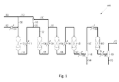
- Figure 1 illustrates a methanation process 100 with an ejector according to prior art.
- the methanation process shown in figure 1 relates to a methanation process 100 with four adiabatic methanation reactors 124, 134, 140, 162 and an ejector 118.
- a fresh synthesis gas 102 is heated 104 and led to a sulfur guard 112 in addition with steam 108, providing a desulfurized synthesis gas 114.
- the desulfurized synthesis gas 114 is mixed with a mixture of steam and methane rich recycled gas 120 in order to obtain a first methanation reactor feed gas 122 to be inlet to a first methanation reactor 124.
- the first methanation reactor feed gas 122 is directed to a first methanation reactor 124, providing a first methane rich gas 126, which is cooled in a heat exchanger 128.
- a part of the first methane rich gas 126 is recycled around the first methanation reactor 124, driven by an ejector 118 with steam 110 as a motive gas.
- the part 132 of the first methane rich gas which is not recycled, is allowed to react further in a second methanation reactor 134 and in a third methanation reactor 140 with intermediate cooling 138 of a second stage methane rich gas 136 from the second methanation reactor 134 and intermediate cooling 144 of a third stage methane rich gas 142 from the third methanation reactor 140.
- water 148 Prior to a fourth and final methanation reactor 162, water 148 is condensed, after cooling 144, in a separator 146 in order to shift the reaction equilibrium of a final methanation feed gas 150.
- the final methanation feed gas 150 is subsequently heated in 160 and led to a final methanation reactor 162 resulting in a final stage methane rich gas 164.
- the final stage methane rich gas 164 led from the final methanation reactor 162 is cooled 166 and led to a separator 168 in order to separate water 170 from the final stage methane rich gas 164.
- the separator 168 is arranged to separate water 170 from the final stage methane rich gas and thereby produce a synthetic natural gas 172.
- Figure 2 illustrates a methanation process 200 with a compressor according to prior art.
- the methanation process shown in figure 2 relates to a methanation process 200 with four adiabatic methanation reactors 224, 234, 240, 262 and a compressor 254.
- a feedstock gas 202 e.g. a synthesis gas
- a sulfur guard 212 in addition with steam 208, providing a desulfurized synthesis gas 214.
- the desulfurized synthesis gas 214 is mixed with a mixture of steam 210 and methane rich gas recycled 256 in order to obtain a first methanation feed gas 222 to be inlet to a first methanation reactor 224.
- the first methanation feed gas 222 is directed to a first methanation reactor 224, providing a first stage methane rich gas 226, which is cooled in a heat exchanger 228. Subsequently, the cooled, first methane rich gas 226 is driven to a second methanation reactor 234, providing a second stage methane rich gas 236, and thereafter to a third methanation reactor 240, with intermediate cooling the second stage methane rich gas 236.
- water 248 Prior to a fourth and final methanation reactor 262, water 248 is condensed, after cooling 244, in a separator 246 in order to shift the reaction equilibrium of a final methanation feed gas 250.
- a part of the final methanation feed gas 250 is recycled as recycled methane rich gas 252 to the first methanation 224, via a cold compressor 254, and heated by means of a heat exchanger 255, providing the recycle stream 256.
- the part 258 of the final methanation feed gas not recycled is heated 260 and allowed to react further in a fourth and final methanation reactor 262 resulting in a final stage methane rich gas 264.
- the final stage methane rich gas 264 is cooled 266 and led to a separator 268 in order to separate water 270 from the final stage methane rich gas 264 and thereby produce a synthetic natural gas 272.
- Figure 3 illustrates a methanation process 300 with an ejector and a compressor according to the invention.
- the methanation process 300 shown in Figure 3 is a methanation process with four adiabatic methanation reactors 324, 334, 340, 362, an ejector 318 and a compressor 354.
- a feedstock gas 302 e.g. a synthesis gas comprising carbon monoxide and/or carbon dioxide, and hydrogen
- a feedstock gas 302 is heated 304 and directed to a sulfur guard 312 in addition with steam 308 from a source 306 or steam, providing a desulfurized feedstock gas 314.
- a sulfur guard 312 in addition with steam 308 from a source 306 or steam, providing a desulfurized feedstock gas 314.
- the desulfurized synthesis gas 314 is mixed with a mixture 320 of steam, a first recycle stream 330 of methane rich gas and a second recycle stream 356 of methane rich gas in order to obtain a feed gas 322 for the first methanation reactor.
- the first recycle is driven by an ejector 318 with steam 310 from the steam source 306 as a motive gas.
- the feed gas 322 is directed to a first methanation reactor 324, providing a first gas 326 rich in methane; this first methane rich gas 326 is subsequently cooled in a heat exchanger 328.
- the first part 330 of the first methane rich gas 326 is recycled back to the first methanation reactor 324.
- This first part 330 of the first gas is driven together with steam 310 by the ejector 318, providing the first recycle stream 320.
- the part 332 of the first methane rich gas 326 which is not recycled is allowed to react further in a second methanation reactor 334 providing a second stage methane rich gas 336 and is cooled 338.
- the cooled second stage methane rich gas 336 is allowed to react further in a third methanation reactor 340 providing a third stage methane rich gas 342 which is cooled 344.
- the cooled third stage methane rich gas is led to a separator 346 in order to condense water 348, resulting in a second gas 350 rich in methane.
- the separation of water from the cooled third stage methane rich gas 342 ensures that the equilibrium is shifted in further methanation reactor.
- a first part 352 of the second gas 350 is recycled to the feed gas to the first methanation reactor 324.
- the recycling of the first part 352 of the second gas 350 is driven or caused by a cold compressor 354.
- the first part 352 of the second gas 350 is heated by a heat exchanger 355, providing a second recycle stream 356 of methane rich gas.
- the second recycle stream of methane rich gas 356 is mixed with the desulfurized synthesis gas 314 and with a first recycle of methane rich gas 320 at or upstream of an inlet to the first methanation reactor 324 with methanation catalyst.
- the fresh synthesis gas 302 may be provided directly to the first methanation reactor 324 together with steam added by the ejector 318, the first part 330 of the first methane rich gas 326 recycled and the second recycle stream of methane rich gas 356.
- a second part 358 of the second gas i.e. the part of methane rich gas 350 not recycled, is heated 360 and allowed to react further in a fourth and final methanation reactor 362.
- a final stage methane rich gas 364 exiting the fourth reactor 362 is cooled 366 and led to a separator 368.
- water 370 is separated from the cooled final stage methane rich gas 364 and the remaining gas 372 is the methane rich product gas 372 in the form of a synthetic natural gas 372.
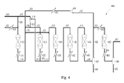
- Figure 4 illustrates a methanation process 400 with an ejector 418 and a compressor 454 according to the invention, the process comprising a split-flow around the first methanation reactor 424.
- the methanation process 400 shown in figure 4 is a methanation process with five adiabatic methanation reactors 424, 434, 440, 444, 462, an ejector 418 and a compressor 454.
- a feedstock gas 402 e.g. a synthesis gas comprising carbon oxides and hydrogen
- a feedstock gas 402 is heated in a heat exchanger 404 and directed to a sulfur guard 412 in addition with steam 408, providing a desulfurized synthesis gas 414.
- the desulfurized synthesis gas 414 is heated in a heat exchanger 413. It should be noted, however, that if the methanation catalysts in the methanation reactors 424, 434, 440, 444, 462 are insensitive to sulfur or if sulfur is absent in the feedstock gas 402, the process 400 could do without the sulfur guard 412.
- the desulfurized synthesis gas 414 is split into a first part 415 and a second part 421.
- the first part 415 of the desulfurized synthesis gas is mixed with a second recycle stream 456 of methane rich gas in order to provide stream 416.
- the mixed stream 416 is mixed with a mixture 420 of steam, a first recycle stream 423 of methane rich gas in order to obtain a feed gas 422 for the first methanation reactor 424.
- the first recycle is driven by an ejector 418 with steam 410 from a steam source 406 as a motive gas.
- the second recycle is driven by a cold compressor 454.
- the feed gas 422 is directed to a first methanation reactor 424, providing a first methane rich gas 426.
- the first methane rich gas 426 is subsequently cooled in a heat exchanger 425.
- the first part 423 of the first methane rich gas 426 is recycled back to the first methanation reactor 424.
- This first part 423 of the first gas is driven together with steam 410 by the ejector 418, providing the first recycle stream 420.
- the part 427 of the first methane rich gas 426, which is not recycled, is mixed with a second part 421 of the desulfurized synthesis gas 414.
- the mixture 428 of the non-recycled part 427 of the first methane rich gas and the second part 421 of the desulfurized synthesis gas is allowed to react further in a second methanation reactor 434, a third methanation reactor 440 and a fourth methanation reactor 444 with intermediate cooling of the second stage 437 and third stage 443 methane rich gas, by means of the heat exchangers 436, 442.
- the fourth stage methane rich gas 446 exiting from the fourth methanation reactor 444 is cooled by the heat exchanger 445.
- the cooled fourth stage methane rich gas 446 is led to a separator 447 in order to condense water 448, resulting in a second gas 450 rich in methane.
- the separation of water from the cooled fourth stage methane rich gas 446 ensures that the equilibrium is shifted in a further methanation reactor.
- a first part 452 of the second gas 450 is recycled to the feed gas to the first methanation reactor 424.
- the recycling of the first part 452 of the second gas 450 is driven or caused by a cold compressor 454.
- the first part 452 of the second gas 450 is heated by a heat exchanger 455, providing a second recycle stream 456 of methane rich gas.
- the second recycle stream of methane rich gas 456 is mixed with the first part 415 of the desulfurized synthesis gas 414 and with a first recycle of methane rich gas 423 at or upstream of an inlet to the first methanation reactor 324 with methanation catalyst.
- a first part of the fresh synthesis gas 402 may be provided directly to the first methanation reactor 424 together with steam added by the ejector 418, the first part 430 of the first methane rich gas 423 recycled and the second recycle stream of methane rich gas 456, whilst a second part of the fresh synthesis gas 402 may be provided to the second methanation reactor 434.
- a second part 458 of the second gas i.e. the part of methane rich gas 450 not recycled, is heated in a heat exchanger 460 and allowed to react further in a fifth and final methanation reactor 462.
- a final stage methane rich gas 464 exiting the fifth reactor 462 is cooled in a heat exchanger 466 and led to a separator 468.
- water 470 is separated from the cooled final stage methane rich gas 464 and the remaining gas 472 is the methane rich product gas 472 in the form of a synthetic natural gas 472.
- composition of the fresh synthesis gas used in the processes shown in of Figure 1 , Figure 2 and Figure 4 corresponds to that of the fresh synthesis gas used in the first example, the example "Ex I", of figure 3 .
- Example II the composition of final SNG product has also been calculated for a gas with another composition, as indicated in Table 1.
- Table I Fresh synthesis gas composition Nm 3 /h Mole% Nm 3 /h Mole% Fig. 3 - Ex I Fig 1 , 2 , 4 Fig.
- Example II of Figure 3 It is seen from Table I, that the fresh synthesis gas used in Example II of Figure 3 is somewhat harsher, due to the higher content of C2+ gas.
- the C2+ gas is substantially exclusively ethane C 2 H 6
- the C2+ gas in Ex II of figure 3 comprises two thirds ethane C 2 H 6 and one third propane C 3 H 8 .
- Tables 2 and 3 below show the low heating value and the composition of the final methane rich product gas from the processes shown in figure 1-4 , with the fresh synthesis gas as indicated in Table 1.
- Table 2 Final SNG Product - Low Heating Value
- Figure 1 Figure 2
- Figure 3 Ex I
- Figure 3 Ex II Figure 4 LHV [kcal/N m 3 ] 8,273 8,383 8,384 8,436 8,393
- Table 3 Final SNG Product - Composition (mole%)
- Tables 2 and 3 above show that the process 100 shown in figure 1 , having an ejector for recycling around the first methanation reactor 124, results in a final product gas comprising 95.5 mole% of CH 4 and having a Lower Heating Value (LHV) of 8,226 kcal/Nm 3 .
- LHV Lower Heating Value
- the tables show that the process 200 of figure 2 comprising a cold compressor for recycling methane rich gas from a third methanation reactor 240 to the first methanation reactor 224, results in a final product gas comprising 97.4 mole% of CH 4 and having a LHV of 8,359 kcal/Nm 3 .
- Table 4 indicates the shaft power necessary for driving the compressor in the examples shown in figures 1-4 as well as the methane content of the product gas. It is clear that the embodiments of the invention shown in figures 3 and 4 provides a product gas with a comparable methane content to the embodiment shown in figure 2 , whilst the power consumption for driving the process is reduced considerably. Compared to the embodiment where only an ejector is used, figure 1 , the power consumed for driving the processes of the invention, shown in figures 3 and 4 , is higher; however, the methane content in the product gas is also higher.
- the carbon limit of the first methanation reactor 224, 424 of figures 2 and 4 is comparable to that of the first methanation reactor 324 of figure 3 (for both gas compositions of Ex I and Ex II). Even though the carbon limit of the first methanation reactor of the processes of figures 2-4 is somewhat lower than that of the process shown in figure 1 , at least partly due to lower water content, the carbon limit of the first methanation reactor of the processes in figures 2-4 is sufficient.
- the process of the invention whereby an ejector adding steam is used together with a cold compressor to drive two independent recycle streams is suitable for the production of methane rich gas whilst controlling the extent of carbon formation. It should be noted, that the process of figure 3 even the harsher gas of Ex II
Landscapes
- Chemical & Material Sciences (AREA)
- Oil, Petroleum & Natural Gas (AREA)
- Engineering & Computer Science (AREA)
- Chemical Kinetics & Catalysis (AREA)
- General Chemical & Material Sciences (AREA)
- Organic Chemistry (AREA)
- Organic Low-Molecular-Weight Compounds And Preparation Thereof (AREA)
Priority Applications (2)
| Application Number | Priority Date | Filing Date | Title |
|---|---|---|---|
| EP14191663.5A EP3018190A1 (de) | 2014-11-04 | 2014-11-04 | Verfahren zur Herstellung von methanreichem Gas |
| PCT/EP2015/075089 WO2016071192A1 (en) | 2014-11-04 | 2015-10-29 | Process for production of methane rich gas |
Applications Claiming Priority (1)
| Application Number | Priority Date | Filing Date | Title |
|---|---|---|---|
| EP14191663.5A EP3018190A1 (de) | 2014-11-04 | 2014-11-04 | Verfahren zur Herstellung von methanreichem Gas |
Publications (1)
| Publication Number | Publication Date |
|---|---|
| EP3018190A1 true EP3018190A1 (de) | 2016-05-11 |
Family
ID=51844625
Family Applications (1)
| Application Number | Title | Priority Date | Filing Date |
|---|---|---|---|
| EP14191663.5A Withdrawn EP3018190A1 (de) | 2014-11-04 | 2014-11-04 | Verfahren zur Herstellung von methanreichem Gas |
Country Status (2)
| Country | Link |
|---|---|
| EP (1) | EP3018190A1 (de) |
| WO (1) | WO2016071192A1 (de) |
Cited By (2)
| Publication number | Priority date | Publication date | Assignee | Title |
|---|---|---|---|---|
| GB2537219A (en) * | 2015-03-03 | 2016-10-12 | Johnson Matthey Davy Technologies Ltd | Process |
| CN106190382A (zh) * | 2016-07-16 | 2016-12-07 | 中国科学院山西煤炭化学研究所 | 煤制合成气进行甲烷化合成代用天然气的工艺 |
Families Citing this family (2)
| Publication number | Priority date | Publication date | Assignee | Title |
|---|---|---|---|---|
| FR3067719B1 (fr) | 2017-06-20 | 2021-05-28 | Michel Bonhomme | Procede et dispositif de production de biomethane en reacteur compartimente en voie visqueuse |
| CN108018103A (zh) * | 2017-12-15 | 2018-05-11 | 新地能源工程技术有限公司 | 一种火山型温度序列甲烷合成工艺 |
Citations (5)
| Publication number | Priority date | Publication date | Assignee | Title |
|---|---|---|---|---|
| US4124628A (en) * | 1977-07-28 | 1978-11-07 | Union Carbide Corporation | Serial adiabatic methanation and steam reforming |
| US20100272619A1 (en) * | 2009-04-22 | 2010-10-28 | General Electric Company | Method and apparatus for substitute natural gas generation |
| CN102517108A (zh) * | 2011-12-15 | 2012-06-27 | 西南化工研究设计院 | 一种利用焦炉气制液化天然气联产液氨的工艺 |
| WO2012084076A1 (en) * | 2010-12-20 | 2012-06-28 | Haldor Topsøe A/S | Process for the production of methane rich gas |
| WO2014060168A2 (de) * | 2012-10-17 | 2014-04-24 | Rohöl-Aufsuchungs Aktiengesellschaft Vorstandsbereich Technik | Vorrichtung zur erdgasverdichtung und verfahren zur methanherstellung |
Family Cites Families (1)
| Publication number | Priority date | Publication date | Assignee | Title |
|---|---|---|---|---|
| CN102660339B (zh) * | 2012-04-27 | 2014-04-30 | 阳光凯迪新能源集团有限公司 | 基于生物质气化与甲烷化的燃气-蒸汽高效联产工艺及系统 |
-
2014
- 2014-11-04 EP EP14191663.5A patent/EP3018190A1/de not_active Withdrawn
-
2015
- 2015-10-29 WO PCT/EP2015/075089 patent/WO2016071192A1/en active Application Filing
Patent Citations (5)
| Publication number | Priority date | Publication date | Assignee | Title |
|---|---|---|---|---|
| US4124628A (en) * | 1977-07-28 | 1978-11-07 | Union Carbide Corporation | Serial adiabatic methanation and steam reforming |
| US20100272619A1 (en) * | 2009-04-22 | 2010-10-28 | General Electric Company | Method and apparatus for substitute natural gas generation |
| WO2012084076A1 (en) * | 2010-12-20 | 2012-06-28 | Haldor Topsøe A/S | Process for the production of methane rich gas |
| CN102517108A (zh) * | 2011-12-15 | 2012-06-27 | 西南化工研究设计院 | 一种利用焦炉气制液化天然气联产液氨的工艺 |
| WO2014060168A2 (de) * | 2012-10-17 | 2014-04-24 | Rohöl-Aufsuchungs Aktiengesellschaft Vorstandsbereich Technik | Vorrichtung zur erdgasverdichtung und verfahren zur methanherstellung |
Non-Patent Citations (2)
| Title |
|---|
| HEINZ HILLER: "Gas Production", 15 June 2006 (2006-06-15), XP055124312, Retrieved from the Internet <URL:http://onlinelibrary.wiley.com/store/10.1002/14356007.a12_169.pub2/asset/a12_169.pdf?v=1&t=hwm5zfw4&s=9bfedd1f9ab59af4510478f91d96e8f5b3978437> [retrieved on 20140619], DOI: 10.1002/14356007.a12 * |
| JENS ROSTRUP-NIELSEN; LARS J. CHRISTIANSEN: "Concepts in Syngas Manufacture", CATALYTIC SCIENCE SERIES, vol. 10, 2011, pages 233 - 235 |
Cited By (4)
| Publication number | Priority date | Publication date | Assignee | Title |
|---|---|---|---|---|
| GB2537219A (en) * | 2015-03-03 | 2016-10-12 | Johnson Matthey Davy Technologies Ltd | Process |
| GB2537219B (en) * | 2015-03-03 | 2017-04-26 | Johnson Matthey Davy Technologies Ltd | Process for producing substitute natural gas |
| CN106190382A (zh) * | 2016-07-16 | 2016-12-07 | 中国科学院山西煤炭化学研究所 | 煤制合成气进行甲烷化合成代用天然气的工艺 |
| CN106190382B (zh) * | 2016-07-16 | 2019-08-06 | 中国科学院山西煤炭化学研究所 | 煤制合成气进行甲烷化合成代用天然气的工艺 |
Also Published As
| Publication number | Publication date |
|---|---|
| WO2016071192A1 (en) | 2016-05-12 |
Similar Documents
| Publication | Publication Date | Title |
|---|---|---|
| Saeidi et al. | Hydrogen production: Perspectives, separation with special emphasis on kinetics of WGS reaction: A state-of-the-art review | |
| Basile et al. | Methanol: science and engineering | |
| AU2004295295B2 (en) | Control of CO2 emissions from a Fischer-Tropsch facility by use of dual functional syngas conversion | |
| AU2004295297B2 (en) | Control of CO2 emissions from a Fischer-Tropsch facility by use of multiple reactors | |
| US7879919B2 (en) | Production of hydrocarbons from natural gas | |
| US9145525B2 (en) | Acid gas management in liquid fuel production process | |
| JP2012514039A (ja) | メタンリッチガスの生成方法 | |
| US20080098654A1 (en) | Synthetic fuel production methods and apparatuses | |
| EP0574633A1 (de) | Trockenes, schwefelfreies Methan-angereichertes Synthese- oder Brenngas | |
| US8816137B2 (en) | Efficient and environmentally friendly processing of heavy oils to methanol and derived products | |
| WO2009007061A1 (en) | Process to produce a methane rich gas mixture from gasification derived sulphur containing synthesis gases | |
| WO2015012882A1 (en) | Process and catalyst system for the production of high quality syngas from light hydrocarbons and carbon dioxide | |
| JP2010144183A (ja) | 合成ガス及び高価値製品へのlpg及びch4の変換方法 | |
| CN102918136A (zh) | 生产烃组合物的方法 | |
| BR112013032890B1 (pt) | Método para ajustar a proporção de hidrogênio para monóxido de carbono em gás de síntese | |
| EP3018190A1 (de) | Verfahren zur Herstellung von methanreichem Gas | |
| CA2892149A1 (en) | Hybrid plant for liquid fuel production and method for operating it where a gasification unit in the hybrid plant is operating at less than its design capacity or is not operational | |
| JP4231415B2 (ja) | 液体燃料へ転化される天然ガス中のco2レベルの低下 | |
| WO2018072989A1 (en) | Gasification process employing acid gas recycle | |
| Speight | Gasification processes for syngas and hydrogen production | |
| GB2593179A (en) | Production of hydrocarbons | |
| Koytsoumpa et al. | Modelling of methanol production via combined gasification and power to fuel | |
| WO2012084076A1 (en) | Process for the production of methane rich gas | |
| CA2872194C (en) | Process for co-producing commercially valuable products from byproducts of fischer-tropsch process for hydrocarbon fuel formulation in a gtl environment | |
| US20150322358A1 (en) | Purification of a raw gas by hydrogenation |
Legal Events
| Date | Code | Title | Description |
|---|---|---|---|
| PUAI | Public reference made under article 153(3) epc to a published international application that has entered the european phase |
Free format text: ORIGINAL CODE: 0009012 |
|
| AK | Designated contracting states |
Kind code of ref document: A1 Designated state(s): AL AT BE BG CH CY CZ DE DK EE ES FI FR GB GR HR HU IE IS IT LI LT LU LV MC MK MT NL NO PL PT RO RS SE SI SK SM TR |
|
| AX | Request for extension of the european patent |
Extension state: BA ME |
|
| STAA | Information on the status of an ep patent application or granted ep patent |
Free format text: STATUS: REQUEST FOR EXAMINATION WAS MADE |
|
| STAA | Information on the status of an ep patent application or granted ep patent |
Free format text: STATUS: THE APPLICATION HAS BEEN WITHDRAWN |
|
| 17P | Request for examination filed |
Effective date: 20161108 |
|
| RBV | Designated contracting states (corrected) |
Designated state(s): AL AT BE BG CH CY CZ DE DK EE ES FI FR GB GR HR HU IE IS IT LI LT LU LV MC MK MT NL NO PL PT RO RS SE SI SK SM TR |
|
| 18W | Application withdrawn |
Effective date: 20161130 |