US20080098654A1 - Synthetic fuel production methods and apparatuses - Google Patents
Synthetic fuel production methods and apparatuses Download PDFInfo
- Publication number
- US20080098654A1 US20080098654A1 US11/563,243 US56324306A US2008098654A1 US 20080098654 A1 US20080098654 A1 US 20080098654A1 US 56324306 A US56324306 A US 56324306A US 2008098654 A1 US2008098654 A1 US 2008098654A1
- Authority
- US
- United States
- Prior art keywords
- synthesis gas
- carbon
- gas
- carbon dioxide
- coal
- Prior art date
- Legal status (The legal status is an assumption and is not a legal conclusion. Google has not performed a legal analysis and makes no representation as to the accuracy of the status listed.)
- Abandoned
Links
- 238000004519 manufacturing process Methods 0.000 title claims abstract description 159
- 239000000446 fuel Substances 0.000 title claims abstract description 136
- 239000007789 gas Substances 0.000 claims abstract description 285
- 239000007788 liquid Substances 0.000 claims abstract description 232
- 150000002430 hydrocarbons Chemical class 0.000 claims abstract description 171
- 229930195733 hydrocarbon Natural products 0.000 claims abstract description 169
- 230000015572 biosynthetic process Effects 0.000 claims abstract description 137
- 238000003786 synthesis reaction Methods 0.000 claims abstract description 135
- OKTJSMMVPCPJKN-UHFFFAOYSA-N Carbon Chemical compound [C] OKTJSMMVPCPJKN-UHFFFAOYSA-N 0.000 claims abstract description 85
- 229910052799 carbon Inorganic materials 0.000 claims abstract description 65
- 238000006243 chemical reaction Methods 0.000 claims abstract description 58
- 238000000034 method Methods 0.000 claims description 366
- CURLTUGMZLYLDI-UHFFFAOYSA-N Carbon dioxide Chemical compound O=C=O CURLTUGMZLYLDI-UHFFFAOYSA-N 0.000 claims description 167
- UFHFLCQGNIYNRP-UHFFFAOYSA-N Hydrogen Chemical compound [H][H] UFHFLCQGNIYNRP-UHFFFAOYSA-N 0.000 claims description 95
- 239000001569 carbon dioxide Substances 0.000 claims description 87
- 229910002092 carbon dioxide Inorganic materials 0.000 claims description 87
- 239000001257 hydrogen Substances 0.000 claims description 86
- 229910052739 hydrogen Inorganic materials 0.000 claims description 86
- 239000003245 coal Substances 0.000 claims description 84
- 238000002309 gasification Methods 0.000 claims description 62
- UGFAIRIUMAVXCW-UHFFFAOYSA-N Carbon monoxide Chemical compound [O+]#[C-] UGFAIRIUMAVXCW-UHFFFAOYSA-N 0.000 claims description 55
- 229910002091 carbon monoxide Inorganic materials 0.000 claims description 55
- VNWKTOKETHGBQD-UHFFFAOYSA-N methane Chemical compound C VNWKTOKETHGBQD-UHFFFAOYSA-N 0.000 claims description 10
- 239000000203 mixture Substances 0.000 claims description 4
- 239000012530 fluid Substances 0.000 claims description 3
- 239000002699 waste material Substances 0.000 claims description 3
- 239000002028 Biomass Substances 0.000 claims description 2
- 239000003077 lignite Substances 0.000 claims description 2
- 239000003345 natural gas Substances 0.000 claims description 2
- 239000004058 oil shale Substances 0.000 claims description 2
- -1 refuse Substances 0.000 claims description 2
- 239000004215 Carbon black (E152) Substances 0.000 abstract description 128
- 239000003344 environmental pollutant Substances 0.000 abstract description 35
- 231100000719 pollutant Toxicity 0.000 abstract description 35
- 239000000047 product Substances 0.000 description 227
- 229910001868 water Inorganic materials 0.000 description 45
- XLYOFNOQVPJJNP-UHFFFAOYSA-N water Substances O XLYOFNOQVPJJNP-UHFFFAOYSA-N 0.000 description 42
- QVGXLLKOCUKJST-UHFFFAOYSA-N atomic oxygen Chemical compound [O] QVGXLLKOCUKJST-UHFFFAOYSA-N 0.000 description 32
- 239000001301 oxygen Substances 0.000 description 32
- 229910052760 oxygen Inorganic materials 0.000 description 32
- 238000000926 separation method Methods 0.000 description 28
- 238000011084 recovery Methods 0.000 description 23
- MYMOFIZGZYHOMD-UHFFFAOYSA-N Dioxygen Chemical compound O=O MYMOFIZGZYHOMD-UHFFFAOYSA-N 0.000 description 12
- 150000002431 hydrogen Chemical class 0.000 description 11
- 238000004064 recycling Methods 0.000 description 11
- 238000010926 purge Methods 0.000 description 10
- RWSOTUBLDIXVET-UHFFFAOYSA-N Dihydrogen sulfide Chemical compound S RWSOTUBLDIXVET-UHFFFAOYSA-N 0.000 description 9
- 238000010586 diagram Methods 0.000 description 9
- ZIBGPFATKBEMQZ-UHFFFAOYSA-N triethylene glycol Chemical compound OCCOCCOCCO ZIBGPFATKBEMQZ-UHFFFAOYSA-N 0.000 description 9
- 230000005611 electricity Effects 0.000 description 8
- 238000005868 electrolysis reaction Methods 0.000 description 8
- 238000010248 power generation Methods 0.000 description 8
- GVGLGOZIDCSQPN-PVHGPHFFSA-N Heroin Chemical compound O([C@H]1[C@H](C=C[C@H]23)OC(C)=O)C4=C5[C@@]12CCN(C)[C@@H]3CC5=CC=C4OC(C)=O GVGLGOZIDCSQPN-PVHGPHFFSA-N 0.000 description 7
- 230000018044 dehydration Effects 0.000 description 7
- 238000006297 dehydration reaction Methods 0.000 description 7
- 238000004821 distillation Methods 0.000 description 7
- 238000004088 simulation Methods 0.000 description 7
- OKKJLVBELUTLKV-UHFFFAOYSA-N Methanol Chemical compound OC OKKJLVBELUTLKV-UHFFFAOYSA-N 0.000 description 6
- 230000007423 decrease Effects 0.000 description 6
- 239000012528 membrane Substances 0.000 description 6
- IJGRMHOSHXDMSA-UHFFFAOYSA-N Atomic nitrogen Chemical compound N#N IJGRMHOSHXDMSA-UHFFFAOYSA-N 0.000 description 5
- 229910000037 hydrogen sulfide Inorganic materials 0.000 description 5
- 239000002351 wastewater Substances 0.000 description 5
- LCGLNKUTAGEVQW-UHFFFAOYSA-N Dimethyl ether Chemical compound COC LCGLNKUTAGEVQW-UHFFFAOYSA-N 0.000 description 4
- NINIDFKCEFEMDL-UHFFFAOYSA-N Sulfur Chemical compound [S] NINIDFKCEFEMDL-UHFFFAOYSA-N 0.000 description 4
- 239000010866 blackwater Substances 0.000 description 4
- 238000004517 catalytic hydrocracking Methods 0.000 description 4
- 239000012535 impurity Substances 0.000 description 4
- 239000011593 sulfur Substances 0.000 description 4
- 238000004364 calculation method Methods 0.000 description 3
- 238000002485 combustion reaction Methods 0.000 description 3
- 238000007796 conventional method Methods 0.000 description 3
- 230000010354 integration Effects 0.000 description 3
- 239000002893 slag Substances 0.000 description 3
- ATUOYWHBWRKTHZ-UHFFFAOYSA-N Propane Chemical compound CCC ATUOYWHBWRKTHZ-UHFFFAOYSA-N 0.000 description 2
- 239000007795 chemical reaction product Substances 0.000 description 2
- 239000000470 constituent Substances 0.000 description 2
- 238000001035 drying Methods 0.000 description 2
- 230000000694 effects Effects 0.000 description 2
- 230000008030 elimination Effects 0.000 description 2
- 238000003379 elimination reaction Methods 0.000 description 2
- QSHDDOUJBYECFT-UHFFFAOYSA-N mercury Chemical compound [Hg] QSHDDOUJBYECFT-UHFFFAOYSA-N 0.000 description 2
- 229910052753 mercury Inorganic materials 0.000 description 2
- 230000004048 modification Effects 0.000 description 2
- 238000012986 modification Methods 0.000 description 2
- 229910052757 nitrogen Inorganic materials 0.000 description 2
- 238000010791 quenching Methods 0.000 description 2
- 238000002407 reforming Methods 0.000 description 2
- 230000009919 sequestration Effects 0.000 description 2
- 239000004071 soot Substances 0.000 description 2
- 238000003860 storage Methods 0.000 description 2
- 229910052717 sulfur Inorganic materials 0.000 description 2
- RAHZWNYVWXNFOC-UHFFFAOYSA-N sulfur dioxide Inorganic materials O=S=O RAHZWNYVWXNFOC-UHFFFAOYSA-N 0.000 description 2
- OTMSDBZUPAUEDD-UHFFFAOYSA-N Ethane Chemical compound CC OTMSDBZUPAUEDD-UHFFFAOYSA-N 0.000 description 1
- 239000000654 additive Substances 0.000 description 1
- 230000000996 additive effect Effects 0.000 description 1
- 150000001298 alcohols Chemical class 0.000 description 1
- 150000001299 aldehydes Chemical class 0.000 description 1
- 150000001335 aliphatic alkanes Chemical class 0.000 description 1
- 150000001336 alkenes Chemical class 0.000 description 1
- 239000003054 catalyst Substances 0.000 description 1
- 238000006555 catalytic reaction Methods 0.000 description 1
- 150000001875 compounds Chemical class 0.000 description 1
- 230000006835 compression Effects 0.000 description 1
- 238000007906 compression Methods 0.000 description 1
- 238000001816 cooling Methods 0.000 description 1
- 239000000112 cooling gas Substances 0.000 description 1
- 238000009826 distribution Methods 0.000 description 1
- 238000000605 extraction Methods 0.000 description 1
- 239000010881 fly ash Substances 0.000 description 1
- 238000010348 incorporation Methods 0.000 description 1
- VUZPPFZMUPKLLV-UHFFFAOYSA-N methane;hydrate Chemical compound C.O VUZPPFZMUPKLLV-UHFFFAOYSA-N 0.000 description 1
- 238000002156 mixing Methods 0.000 description 1
- 239000003208 petroleum Substances 0.000 description 1
- 239000001294 propane Substances 0.000 description 1
- 238000000197 pyrolysis Methods 0.000 description 1
- 238000007670 refining Methods 0.000 description 1
- 239000002910 solid waste Substances 0.000 description 1
- 238000000629 steam reforming Methods 0.000 description 1
- 239000000126 substance Substances 0.000 description 1
- 239000013589 supplement Substances 0.000 description 1
Images


Classifications
-
- C—CHEMISTRY; METALLURGY
- C10—PETROLEUM, GAS OR COKE INDUSTRIES; TECHNICAL GASES CONTAINING CARBON MONOXIDE; FUELS; LUBRICANTS; PEAT
- C10G—CRACKING HYDROCARBON OILS; PRODUCTION OF LIQUID HYDROCARBON MIXTURES, e.g. BY DESTRUCTIVE HYDROGENATION, OLIGOMERISATION, POLYMERISATION; RECOVERY OF HYDROCARBON OILS FROM OIL-SHALE, OIL-SAND, OR GASES; REFINING MIXTURES MAINLY CONSISTING OF HYDROCARBONS; REFORMING OF NAPHTHA; MINERAL WAXES
- C10G1/00—Production of liquid hydrocarbon mixtures from oil-shale, oil-sand, or non-melting solid carbonaceous or similar materials, e.g. wood, coal
- C10G1/002—Production of liquid hydrocarbon mixtures from oil-shale, oil-sand, or non-melting solid carbonaceous or similar materials, e.g. wood, coal in combination with oil conversion- or refining processes
Definitions
- the present invention relates to processes and systems for converting carbonaceous feedstocks to liquid hydrocarbons and liquid fuel products and, more particularly, to the use of alternative energy sources and recycling processes to provide improved recovery in coal-to-liquid or carbon-to-liquid processes and systems.
- Synthesis gas for use in the Fischer-Tropsch process may be produced by the gasification of coal which produces carbon monoxide and hydrogen.
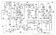
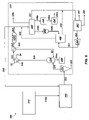
- the coal-to-liquid hydrocarbon (CTL) process 100 may include a number of sub-processes occurring within the CTL process 100 .
- a conventional CTL process 100 may include a coal gasification process 110 , a gas and heat recovery process 120 , a gas cleanup process 130 , a Fischer-Tropsch process 160 , and a heat recovery and power generation process 190 .
- Each of the sub-processes illustrated in FIG. 1 is separated by dashed lines.
- the coal gasification process 110 of the CTL process 100 includes a dryer 112 , a pulverizer 114 , an entrained flow gasifier 116 , and an air separation unit 118 .
- Coal 111 for use in the coal gasification process 110 is fed to one or more dryers 112 to reduce moisture in the coal 111 .
- Moisture extracted from the coal 111 may be discharged from the dryers 112 .
- a dryer 112 may include a heat exchanger or other conventional drying process typically used with CTL processes 100 .
- the dried coal 113 is fed to a pulverizer 114 where the dried coal 113 is pulverized, crushed, or otherwise reduced to a sufficient size for coal gasification.
- the pulverized coal 115 is fed to the entrained flow gasifier 116 where the coal is gasified.
- Air 119 fed to the air separation unit 118 such as a cryogenic air separation unit, is converted into nitrogen (N 2 ) and oxygen (O 2 ).
- the nitrogen is purged as nitrogen stream 118 b while the oxygen stream 118 a is fed to the entrained flow gasifier 116 .
- the pulverized coal 115 fed to the entrained flow gasifier 116 is gasified with oxygen from the oxygen stream 118 a in the presence of steam 50 fed to the entrained flow gasifier 116 .
- Boiler feed water (BFW) 52 may also be fed to the entrained flow gasifier to absorb heat produced in the gasification process, forming a medium pressure steam (MPS) 54 which may be removed from the entrained flow gasifier 116 and used elsewhere in the CTL process 100 .
- MPS medium pressure steam
- the combustion, pyrolysis, and gasification of the pulverized coal 115 fed to the entrained flow gasifier 116 produces a syngas product 116 a and a slag 116 b .
- the syngas product 116 a is removed from the entrained flow gasifier 116 and the coal gasification process 110 and is fed to a gas and heat recovery process 120 .
- Slag 116 b is removed from the entrained flow gasifier 116 and is disposed of or otherwise utilized according to conventional methods.
- the syngas product 116 a from the entrained flow gasifier 116 includes carbon monoxide (CO), hydrogen (H 2 ), and other gas products.
- the hot syngas product 116 a is fed to a syngas cooler 122 in the gas and heat recovery process 120 .
- the syngas cooler 122 cools the hot syngas product 116 a and produces a cool syngas product 123 which is withdrawn from the syngas cooler 122 .
- the cool syngas product 123 is then fed to a gas cleanup process 130 .
- the hot syngas product 116 a fed to the syngas cooler 122 may also be combined with a quench gas 143 from the gas cleanup process 130 , the quench gas having been fed through one or more compressors 124 .
- Boiler feed water 52 may also be fed to the syngas cooler 122 .
- the boiler feed water 52 absorbs heat within the syngas cooler 122 producing steam, such as high pressure steam 56 and medium pressure steam 54 .
- High pressure steam 56 produced in the syngas cooler 122 is discharged.
- High pressure steam 56 may also be fed to the sour shift reactor 138 of the gas cleanup process 130 .
- Medium pressure steam 54 produced in the syngas cooler 122 may be recovered and used elsewhere in the CTL process 100 .
- the gas cleanup process 130 is used to remove pollutants and other unwanted products from the cool syngas product 123 fed to the gas cleanup process 130 .
- the gas cleanup process 130 includes a cyclone 132 , a water scrubber 134 , a black water system 136 , a sour shift reactor 138 , a heat exchanger 140 , a condenser 142 , and an activated carbon bed 144 .
- the gas cleanup process 130 also includes equipment for removing hydrogen sulfide (H 2 S) and carbon dioxide (CO 2 ) from synthesis gas.
- Cool syngas product 123 fed to the gas cleanup process 130 is fed to a cyclone 132 to remove flash 133 and other particulates from the cool syngas product 123 .
- the cool syngas product 123 is then fed to a water scrubber 134 with water 60 .
- the water scrubber 134 removes pollutants and other impurities from the cool syngas product 123 and discharges the removed pollutants and other impurities with water 60 in a waste water stream 134 a .
- a scrubbed syngas product 135 is split into a first scrubbed syngas stream 135 a that is fed to the sour shift reactor 138 and a second scrubbed syngas stream 135 b that bypasses the sour shift reactor 138 and is combined with the shifted syngas product 138 a from the sour shift reactor 138 .
- the first scrubbed syngas stream 135 a fed to the sour shift reactor 138 is combined with high pressure steam 56 fed to the sour shift reactor 138 to produce desired ratios of hydrogen and carbon monoxide for the syngas being produced.
- the shift of the hydrogen and carbon monoxide ratios in the shifted syngas product 138 a from the sour shift reactor 138 may be manipulated such that the combination of the shifted syngas product 138 a with the second scrubbed syngas product 135 b produces a syngas product 139 having a desired ratio of hydrogen and carbon monoxide for the Fischer-Tropsch process 160 .
- the waste water stream 134 a is fed to a black water treatment system 136 for treatment of the waste water stream 134 a according to conventional methods.
- the syngas product 139 is fed to a heat exchanger 140 that cools the syngas product 139 .
- Boiler feed water 52 fed to the heat exchanger 140 may be converted into medium pressure steam 54 , which may be used in other portions of the CTL process 100 .
- the cooled syngas product 141 from the heat exchanger 140 is fed to a condenser 142 where water 60 in the cooled syngas product 141 is condensed and removed from the cooled syngas product 141 .
- the water 60 may be fed to the water scrubber 134 in the gas cleanup process 130 .
- the syngas product 143 from the condenser 142 is fed to an activated carbon bed 144 .
- the activated carbon bed 144 removes unwanted mercury pollutants from the syngas product 143 .
- a portion of the syngas product 143 exiting the activated carbon bed 144 may be removed and fed to the compressor 124 of the gas and heat recovery process 120 and combined with the syngas product 116 a as feed stock to the syngas cooler 122 .
- the remainder of the syngas product 143 is fed to a Rectisol process 146 to further remove hydrogen sulfide (H 2 S) and carbon dioxide (CO 2 ) from the syngas product 143 .
- H 2 S hydrogen sulfide
- CO 2 carbon dioxide
- the Rectisol process 146 removes hydrogen sulfide and carbon dioxide from the syngas product 143 , producing a first product stream 146 a containing hydrogen sulfide and carbon dioxide, a second product stream 146 b containing carbon dioxide, a purge gas 146 c , and a syngas product stream 147 .
- the first product stream 146 a can be fed to a Claus process 148 for removal of sulfur 148 a from the gaseous hydrogen sulfide in the first product stream 146 a .
- the Claus tail gases 148 b are fed to a SCOT process 150 for further treatment before being discharged as a SCOT process purge gas 150 a.
- the second product stream 146 b of carbon dioxide is compressed in a first compressor 152 and then fed to a triethylene glycol (TEG) dehydration process 154 where water is removed from the second product stream 146 b . Water removed from the second product stream 146 b may be used elsewhere in the CTL process 100 .
- Carbon dioxide gas from the TEG process 154 is fed to a compressor 156 where it is cooled to form liquid carbon dioxide 157 .
- the liquid carbon dioxide 157 is pumped to a storage tank or other process for further use.
- the purge gas 146 c from the Rectisol process 146 is released into the environment.
- the Rectisol process 146 , Claus process 148 , SCOT process 150 , and TEG dehydration process 154 are well known processes conventionally used to remove sulfur and carbon dioxide pollutants from CTL processes 100 .
- the syngas product stream 147 is fed to a Fischer-Tropsch process 160 for conversion of the syngas product stream 147 into liquid fuel products.
- the Fischer-Tropsch process 160 illustrated in FIG. 1 includes a first Fischer-Tropsch reactor 162 , a first heat exchanger 164 , a first separation unit 166 , a compressor 168 , a second Fischer-Tropsch reactor 172 , a second heat exchanger 174 , a second separation unit 176 , a hydrocracker 170 , a hydrogen separation membrane 178 , a second compressor 180 , a tank 182 , and distillation columns 184 .
- the syngas product stream 147 from the gas cleanup process 130 contains hydrogen (H 2 ) and carbon monoxide (CO).
- the syngas product stream 147 is fed to the first Fischer-Tropsch reactor 162 where the hydrogen and carbon monoxide in the syngas product stream 147 are converted into liquid fuel products through a catalysis reaction, such as Reaction 1:
- n may be between about 1 and about 42, although n may also be greater than 42.
- n may be between about 1 and about 7
- intermediate hydrocarbons n may be from about 8 to about 13
- heavy hydrocarbons n may be above about 14.
- a first hydrocarbon stream 163 containing both liquid fuel products and gas from the first Fischer-Tropsch reactor 162 is cooled in the first heat exchanger 164 .
- Boiler feed water 52 fed to the first heat exchanger 164 absorbs heat from the first hydrocarbon stream 163 , producing medium pressure steam 54 that is purged for use in other processes.
- the cooled first hydrocarbon stream 163 is fed to the first separation unit 166 where various constituents of the first-hydrocarbon stream 163 are separated. Syngas 167 remaining in the first hydrocarbon stream 163 is separated by the first separation unit 166 and purged to be fed to the second Fischer-Tropsch reactor 172 .
- the liquid fuel products in the first hydrocarbon stream 163 are separated by the first separation unit 166 into two hydrocarbon streams: a first light hydrocarbon product 166 a containing intermediate distillates and light hydrocarbons, and a first heavy hydrocarbon product 166 b containing heavy hydrocarbons.
- the first separation unit 166 also removes water 60 from the first hydrocarbon stream 163 and purges the water 60 from the other products.
- Syngas 167 from the first separation unit 166 is compressed in the compressor 168 and is then fed to the second Fischer-Tropsch reactor 172 where the syngas 167 is catalytically reacted to convert the hydrogen and carbon monoxide in the syngas 167 into liquid fuel products.
- the syngas 167 may be converted into liquid fuel products in accordance with Reaction 1.
- a second hydrocarbon stream 173 from the second Fischer-Tropsch reactor 172 is cooled in the second heat exchanger 174 and fed to the second separation unit 176 .
- Boiler feed water 52 fed to the second heat exchanger 174 absorbs heat from the second hydrocarbon stream 173 , producing medium pressure steam 54 that is purged for use in other processes or other parts of the CTL process 100 .
- the second separation unit 176 separates the second hydrocarbon stream 173 into its various constituents. Water 60 separated from the second hydrocarbon stream 173 is purged from the second separation unit 176 for use elsewhere. Liquid fuel products in the second hydrocarbon stream 173 are separated into two hydrocarbon streams: a second light hydrocarbon product 176 a containing intermediate distillates and light hydrocarbons, and a second heavy hydrocarbon product 176 b containing heavy hydrocarbons.
- the tail gases 177 separated from the second hydrocarbon stream 173 in the second separation unit 176 are fed to the hydrogen separation membrane 178 where the hydrogen (H 2 ) 179 in the tail gases 177 is removed.
- Heavy hydrocarbons produced in the Fischer-Tropsch process 160 are converted to light hydrocarbons or liquid fuel products in the hydrocracker 170 .
- the first heavy hydrocarbon product 166 b and the second heavy hydrocarbon product 176 b produced by the Fischer-Tropsch reactors are mixed together to form a heavy hydrocarbon stream 169 that is fed to the hydrocracker 170 .
- Heavy hydrocarbons 185 from the distillation column 184 are also fed to the hydrocracker 170 .
- Hydrogen 179 separated from the tail gases 177 by the hydrogen separation membrane 178 , is pressurized or compressed in compressor 180 before being fed to the hydrocracker 170 to facilitate the hydrocracking of the heavy hydrocarbons to produce a hydrocarbon product 171 of lighter hydrocarbons or liquid fuel products from the hydrocracker 170 .
- the hydrocarbon product 171 is combined with the second light hydrocarbon product 176 a and then with the first light hydrocarbon product 166 a and mixed in tank 182 to form a light hydrocarbon product 183 .
- the light hydrocarbon product 183 is fed to the distillation column 184 .
- the light hydrocarbon product 183 produced by the Fischer-Tropsch process 160 is distilled into naphtha products 186 and diesel products 187 .
- Heavy hydrocarbons 185 produced in the distillation column 184 are removed from the distillation column 184 and fed to the hydrocracker 170 .
- Purge gases 188 from the distillation column 184 may be combined with the tail gases 177 and fed to the hydrogen separation membrane 178 for separation of hydrogen from the purge gases 188 .
- the CTL process 100 may also include a heat recovery and power generation process 190 .
- the heat recovery and power generation process 190 converts heat recovered from the CTL process 100 into power.
- Recovered steam 58 such as high pressure steam 56 and medium pressure steam 54 , collected in the CTL process 100 is fed to a heat recovery steam generator 194 along with boiler feed water 52 and air 119 .
- Tail gases 191 from the hydrogen separation membrane 178 are combined with air 119 and burned in a gas turbine 192 connected to a generator to produce electricity.
- Exhaust gases 193 from the gas turbine 192 are fed to the heat recovery steam generator 194 to further heat the boiler feed water 52 and recovered steam 58 fed to the heat recovery steam generator 194 .
- Superheated steam 195 produced in the heat recovery steam generator 194 is fed to a condensing steam turbine 196 which produces electricity from the expansion and cooling of the superheated steam 195 .
- the water produced in the condensing steam turbine 196 is fed to a pump 199 and pumped throughout the CTL process 100 to be used as boiler feed water 52 .
- the exhaust gases 193 are cooled in the heat recovery steam generator 194 and are then fed to a stack 198 .
- the gases exiting the stack may be further treated or released into the environment.
- CTL processes 100 such as the one illustrated in FIG. 1 may be used to produce liquid hydrocarbons and liquid fuel products from synthesis gas produced by the gasification of coal, such processes often produce a larger amount of pollutants than do conventional petroleum extraction and refining processes associated with liquid fuel production.
- One of the most prevalent pollutants produced by coal gasification is carbon dioxide (CO 2 ).
- CO 2 carbon dioxide
- Increased production of synthesis gases from coal gasification to supply Fischer-Tropsch processes with sufficient synthesis gas to produce liquid hydrocarbons and liquid fuel products would result in the unwanted increased production of carbon dioxide emissions.
- Proposals to counter the increased carbon dioxide emissions resulting from coal gasification have included proposals to sequester the carbon dioxide or otherwise convert the carbon dioxide produced in such a process prior to release into the environment.
- Carbon dioxide sequestration processes are expensive and add additional costs to liquid hydrocarbon production processes.
- Other proposed alternatives to encourage sequestration or conversion of carbon dioxide to a non-pollutant have also been made, including proposals to tax carbon dioxide emissions from coal gasification and Fischer-Tropsch processes.
- a CTL process 100 such as that illustrated in FIG. 1 may convert about thirty-percent of the carbon contained in the coal fed to the process to liquid hydrocarbons or liquid fuel products. The remaining seventy-percent of the carbon in the coal is converted to carbon dioxide, other pollutants, or solid wastes that must be disposed.
- the conversion of carbon to liquid fuel products in a coal-to-liquid hydrocarbon production process may be improved by modifying a conventional coal-to-liquid hydrocarbon production process or by incorporating the modifications into new process plants.
- the modifications to a coal-to-liquid hydrocarbon production process facilitate the conversion of carbon to liquid fuel products and reduce the amount of carbon-based pollutants produced by a coal-to-liquid hydrocarbon production process.
- a water-splitting process such as an electrolysis or thermochemical process, for producing oxygen may be integrated with a liquid fuel production process, such as a coal-to-liquid hydrocarbon production process, or may be configured to supply oxygen to a liquid fuel production process.
- the oxygen may be used in the liquid fuel production process to gasify coal in the production of a synthesis gas containing hydrogen and carbon monoxide.
- the water-splitting process may produce oxygen from water utilizing conventional electrolysis processes.
- the power or heat required by the water-splitting process to produce oxygen from water may be supplied from a nuclear power source.
- the use of a nuclear power source to produce electricity or power to supply to the water-splitting process decreases the production of pollutants associated with conventional coal-fired electricity generation operations.
- the resulting liquid fuel production process therefore produces fewer pollutants.
- the use of a water-splitting process reduces the need for air separation units conventionally used with gasification processes to produce oxygen, reducing the equipment and operating costs associated with the production of liquid fuels, such as by the gasification of coal.
- the water-splitting process may also produce hydrogen.
- the water-splitting process may be configured to supply the produced hydrogen to the liquid fuel production process.
- hydrogen produced by the water-splitting process may be mixed with synthesis gas produced in the liquid fuel production process to achieve a desired ratio of hydrogen to carbon monoxide in the synthesis gas.
- the hydrogen produced by the water-splitting process may also be used to facilitate hydrocracking of heavy hydrocarbons or liquid fuel products produced from the synthesis gas generated in the liquid fuel production process.
- pollutant gases removed from the synthesis gases produced in a liquid fuel production process may be recycled to a coal gasification process or other synthesis gas production process.
- Carbon-containing compounds and pollutants such as carbon dioxide, carbon monoxide, methane, alkanes, alkenes, alcohols, aldehydes, or other species, produced in a liquid fuel production process may be recycled to a coal gasification process, for example, where the carbon-containing pollutants may be further reacted to produce additional synthesis gas.
- the production of additional synthesis gas from the carbon-containing pollutants improves the yield of liquid hydrocarbons and liquid fuel products produced in the process while reducing the amount of carbon-containing pollutants produced by the process.
- tail gases from a Fischer-Tropsch process associated with a liquid fuel production process may be recycled to generate additional synthesis gas in the process.
- the tail gases may be recycled because they are not needed to supply energy due to the availability of an alternative energy source, such as a nuclear reactor.
- At least a portion of the reaction product of carbon monoxide and hydrogen produced by the reaction of tail gases from a liquid fuel production process may be recycled to a gas cleanup process.
- the reaction product may be mixed with a product gas from a gasification process. The recycling of the carbon monoxide and hydrogen to the gasification process may improve the conversion of the carbon in the carbon-containing fuel into useful synthesis gas products rather than pollutants or unwanted products.
- liquid fuel production processes of various embodiments of the invention provide enhanced yields of liquid hydrocarbons and liquid fuel products per ton of coal or fuel when compared to conventional processes.
- the liquid fuel production processes of embodiments of the invention reduce the production of carbon-containing pollutants in the process.
- FIG. 1 illustrates a process flow and system diagram of a conventional coal-to-liquid hydrocarbon production process
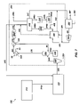
- FIG. 2 illustrates a process flow and system diagram of a coal-to-liquid hydrocarbon production process according to certain embodiments of the invention
- FIG. 4 illustrates a process flow and system diagram of a coal-to-liquid hydrocarbon production process according to certain embodiments of the invention
- FIG. 5 illustrates a process flow and system diagram of a coal-to-liquid hydrocarbon production process according to certain embodiments of the invention
- FIG. 6 illustrates a process flow and system diagram of a liquid fuel production process according to certain embodiments of the invention
- FIG. 7 illustrates a process flow and system diagram of a liquid fuel production process according to certain embodiments of the invention.
- FIG. 8 illustrates a process flow and system diagram of a liquid fuel production process according to certain embodiments of the invention.
- a nuclear power source may be integrated with or incorporated into a liquid fuel production process, such as a coal-to-liquid hydrocarbon production process, to facilitate the production of hydrocarbons and liquid fuel products from coal.
- a liquid fuel production process such as a coal-to-liquid hydrocarbon production process
- the integration of a nuclear power source with a coal-to-liquid hydrocarbon production process, or other liquid fuel production process facilitates the use of alternative processes to produce oxygen (O 2 ) and hydrogen (H 2 ), allowing expensive equipment to be removed from a liquid fuel production process.
- a nuclear power source may be configured to provide electric power, heat, or a combination of electric power and heat to operate a water-splitting process.
- the water-splitting process may be used to generate oxygen and hydrogen from water.
- Oxygen produced by the water-splitting process may be substituted for the oxygen produced by an air separation unit 118 in a conventional CTL process 100 such as the process illustrated in FIG. 1 .
- the alternative source of oxygen provided by the water-splitting process and nuclear power source eliminates the need for an air separation unit in a CTL process 100 .
- Air separation units, such as air separation unit 118 in the conventional CTL process 100 illustrated in FIG. 1 are often expensive to install and expensive to operate. The use of oxygen from a water-splitting process operated with nuclear power may therefore decrease the costs associated with the operation of a coal-to-liquid hydrocarbon production process.
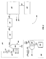
- coal-to-liquid hydrocarbon production processes 200 may include sub-processes such as a coal gasification process 210 , a gas and heat recovery process 220 , a gas cleanup process 230 , a Fischer-Tropsch process 260 , and a heat recovery and power generation process 290 .
- the sub-processes of the coal-to-liquid hydrocarbon production process 200 which do not differ from convention CTL process 100 sub-processes are illustrated as sub-process blocks in FIG. 2 .
- the coal-to-liquid hydrocarbon production process 200 illustrated in FIG. 2 may also include a water-splitting process 300 .
- a water-splitting process 300 may include an electrolysis process or a thermochemical water-splitting process. While various water-splitting processes may be used with various embodiments of the invention, certain embodiments are described with respect to the use of an electrolysis process. It is understood that other water-splitting processes may be used in place of or in combination with an electrolysis process according to various embodiments of the invention.
- a water-splitting process 300 according to embodiments of the invention may include one or more nuclear power sources 302 , one or more electrolyzers 304 , one or more oxygen compressors 312 , and one or more hydrogen compressors 314 .
- the one or more nuclear power sources 302 may include any source of power resulting from nuclear energy.
- multiple high-temperature nuclear reactors may be used to produce electricity 303 capable of operating one or more electrolyzers 304 to produce oxygen 308 and hydrogen 310 from water 306 .
- the oxygen 308 may be compressed by one or more compressors 312 and fed to the entrained flow gasifier 216 of the coal gasification process 210 .
- the introduction of oxygen 308 from the electrolyzers 304 into the entrained flow gasifier 216 eliminates the need for an oxygen supply from an air separation unit.
- Electrolyzers 304 may include conventional electrolyzers 304 such as electrolyzers used in conventional low temperature electrolysis, high temperature electrolysis, or thermochemical processes.
- coal 211 for use in the coal gasification process 210 may be fed to one or more dryers 212 to reduce moisture in the coal 211 .
- the one or more dryers 212 may include heat exchangers or other conventional drying processes.
- the dried coal 213 may be fed to a pulverizer 214 where the dried coal 213 is pulverized, crushed, or otherwise reduced to a sufficient size for coal gasification.
- the pulverized coal 215 may be fed to an entrained flow gasifier 216 to gasify the pulverized coal 215 .
- Oxygen 308 or compressed oxygen 308 from the electrolysis process 300 is also fed to the entrained flow gasifier 216 to facilitate gasification of coal within the entrained flow gasifier 216 .
- Steam 50 and boiler feed water 52 may also be fed to the entrained flow gasifier 216 .
- the gasification of coal within the entrained flow gasifier 216 produces a synthesis gas product 216 a , or syngas, comprising hydrogen and carbon monoxide.
- Slag 216 b produced in the entrained flow gasifier 216 may be removed from the entrained flow gasifier 216 and disposed of as desired.
- Heat generated in the entrained flow gasifier 216 may be used to produce medium pressure steam 54 from the boiler feed water 52 introduced to the entrained flow gasifier 216 .
- the medium pressure steam 54 produced by the entrained flow gasifier 216 may be used elsewhere in the coal-to-liquid hydrocarbon production process 200 as desired.
- coal gasification processes 210 of the coal-to-liquid hydrocarbon production processes 200 described in various embodiments of the invention utilize entrained flow gasifiers 216 to gasify coal
- other gasification units may be substituted for the entrained flow gasifiers 216 .
- gasification units that may be used with coal gasification processes 210 of the various embodiments of the invention may include, but are not limited to, entrained flow gasifiers, counter-current fixed bed gasifiers, co-current fixed bed gasifiers, and fluid bed gasifiers.
- Other coal gasification equipment capable of producing a synthesis gas from the gasification of coal could also be used as a gasification unit.
- the entrained flow gasifier 216 may be configured to gasify coal at a desired temperature.
- the entrained flow gasifier 216 may operate within a temperature range of between about 1300° C. and about 1600° C. Operation within such a temperature range may reduce the formation of carbon dioxide (CO 2 ) and methane (CH 4 ) within the entrained flow gasifier 216 .
- the synthesis gas product 216 a from the coal gasification process 210 may be fed to a gas and heat recovery process 220 which produces a synthesis gas product 223 that may be fed to a gas cleanup process 230 .
- the gas cleanup process 230 removes pollutants such as hydrogen sulfide (H 2 S) and carbon dioxide (CO 2 ) from the synthesis gas product 223 .
- pollutants such as hydrogen sulfide (H 2 S) and carbon dioxide (CO 2 )
- processes such as Rectisol processes, Claus processes, SCOT processes, and TEG dehydration processes may be used to remove pollutants from the synthesis gas product 223 .
- the cleaned synthesis gas from the gas cleanup process 230 may be fed to a Fischer-Tropsch process 260 as a syngas product stream 247 .
- the Fischer-Tropsch process 260 may convert the syngas product stream 247 into naphtha products 286 and diesel products 287 . Tail gases 291 from the Fischer-Tropsch process 260 may be fed to a heat recovery and power generation process 290 to produce electricity.
- hydrogen produced by a water-splitting process 300 in a coal-to-liquid hydrocarbon production process 200 may be added to synthesis gas produced in the coal-to-liquid hydrocarbon production process 200 .
- hydrogen 310 produced by one or more electrolyzers 304 in a water-splitting process 300 may be compressed by one or more compressors 314 and combined with a synthesis gas product stream 247 being fed to a Fischer-Tropsch process 260 of a coal-to-liquid hydrocarbon production process 200 .
- the addition of hydrogen 310 to the synthesis gas product stream 247 may be used to obtain a desired ratio of hydrogen to carbon monoxide within the synthesis gas product stream 247 .
- the synthesis gas fed to the Fischer-Tropsch process 260 may have a hydrogen to carbon monoxide mole ratio (H 2 /CO) of about 2.15.
- H 2 /CO hydrogen to carbon monoxide mole ratio
- the addition of hydrogen 310 to the synthesis gas product stream 247 may also reduce or eliminate the need for water-gas shift chemistry in a gas cleanup process 230 , which removes the need for the inclusion of a sour shift reactor in the coal-to-liquid hydrocarbon production process 200 .
- hydrogen 310 produced in a water-splitting process 300 may be combined with the synthesis gas product stream 247 to achieve the desired ratios of hydrogen and carbon dioxide for a Fischer-Tropsch process 260 .
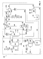
- a synthesis gas product 216 a from the coal gasification process 210 may be introduced into a syngas cooler 222 of a gas and heat recovery process 220 of the coal-to-liquid hydrocarbon production process 200 .
- the syngas cooler 222 cools the hot synthesis gas product 216 a and produces a cool synthesis gas product 223 which is withdrawn from the syngas cooler 222 and fed to the gas cleanup process 230 .
- Boiler feed water 52 fed to the syngas cooler 222 may absorb heat from the hot synthesis gas product 216 a fed to the syngas cooler 222 , resulting in the production of high pressure steam 56 and medium pressure steam 54 which are removed from the syngas cooler 222 for use elsewhere in the coal-to-liquid hydrocarbon production process 200 .
- the syngas cooler 222 may include conventional equipment for cooling gases produced in a coal gasification process 210 .
- the syngas cooler 222 may include one or more convective syngas coolers, radiant syngas coolers, or a combination of convective and radiant syngas coolers.
- the synthesis gas product 223 may be fed to a gas cleanup process 230 .
- the gas cleanup process may include a cyclone 232 , a water scrubber 234 , a black water treatment system 236 , a heat exchanger 240 , a condenser 242 , an activated carbon bed 244 , a Rectisol process 246 , a Claus process 248 , a SCOT process 250 , a TEG dehydration process 254 , and one or more compressors 252 , 256 associated with the TEG dehydration process 254 .
- the gas cleanup process 230 illustrated in FIG. 3 includes single pieces of equipment utilized in the process, multiple pieces of equipment may also be used.
- the heat exchanger 240 may be replaced by two or more heat exchangers 240 as desired. Scaling of the gas cleanup process 230 in order to accommodate desired product flows is feasible.
- Fly ash 233 and other particulates entrained in the synthesis gas product 223 fed to the cyclone 232 may be removed from the cyclone 232 and the synthesis gas product may be fed to a water scrubber 234 .
- Water 60 fed to the water scrubber 234 removes pollutants and other impurities from the synthesis gas product 223 and discharges the water 60 and other impurities as waste water stream 234 a which may be fed to a black water treatment system 236 or other treatment system to treat the waste water stream 234 a .
- a scrubbed synthesis gas product 239 from the water scrubber 234 may be fed to a heat exchanger 240 to cool the scrubbed synthesis gas product 239 .
- Boiler feed water 52 fed to the heat exchanger 240 may absorb heat from the scrubbed synthesis gas 239 , producing steam such as a medium pressure steam 54 that may be used elsewhere in the coal-to-liquid hydrocarbon production process 200 .
- the cooled, scrubbed synthesis gas product 241 may be fed to a condenser 242 where water 60 in the cooled, scrubbed synthesis gas product 241 is recovered.
- the synthesis gas product 243 exiting the condenser 242 may then be treated to further remove pollutants from the synthesis gas product 243 .
- Mercury in the synthesis gas product 243 may be removed by contacting the synthesis gas product 243 with activated carbon in an activated carbon bed 244 .
- the synthesis gas product 243 exiting the activated carbon bed 244 may be fed to one or more processes for removing hydrogen sulfide and carbon dioxide from the synthesis gas product 243 .
- a portion of the synthesis gas product 243 may be diverted to a compressor 224 and then mixed with synthesis gas product 216 a from the coal gasification process 210 .
- a portion of the synthesis gas product 243 exiting the condenser 242 may be diverted to a compressor 224 rather than being fed to the activated carbon bed 244 . This diversion may be in combination with or in place of the diversion of the portion of synthesis gas product 243 exiting the activated carbon bed 244 .
- the synthesis gas product 243 may be fed to a Rectisol process 246 to remove hydrogen sulfide (H 2 S) and carbon dioxide (CO 2 ) from the synthesis gas product 243 .
- the Rectisol process 246 may produce a first product stream 246 a containing hydrogen sulfide and carbon dioxide, a second product stream 246 b containing carbon dioxide, a purge gas 246 c , and a synthesis gas product stream 247 .
- the first product stream 246 a may be further treated by a Claus process 248 and a SCOT process 250 to remove sulfur and carbon dioxide pollutants from the first product stream 246 a and to produce tail gases 250 a that are sufficiently clean to be released into the environment.
- a sulfur product 248 a may be discharged from the Claus process 248 .
- the second product stream 246 b may be compressed in compressor 252 and treated with a TEG dehydration process 254 to purify carbon dioxide from the second product stream 246 b .
- Carbon dioxide gas removed from the second product stream 246 b may be fed to a compressor 256 and cooled to form liquid carbon dioxide 257 .
- the liquid carbon dioxide 257 may be pumped with a pump 258 to a storage container or other process as desired.
- carbon dioxide pollutants recovered from the synthesis gas product 243 may be converted to liquid carbon dioxide for use or sale.
- Rectisol processes 246 , Claus processes 248 , SCOT processes 250 and TEG dehydration processes 254 are well known processes and conventional equipment may be readily utilized to carry out such processes in the gas cleanup process 230 of the coal-to-liquid hydrocarbon production processes 200 according to embodiments of the invention may be readily utilized.
- the synthesis gas product stream 247 produced by the gas cleanup process 230 may be fed to one or more Fischer-Tropsch processes 260 where the synthesis gas product stream 247 is converted into naphtha products 286 and diesel products 287 .
- hydrogen 310 from a water-splitting process 300 may be mixed with the synthesis gas product stream 247 prior to or at the same time that the synthesis gas product stream 247 is fed to the Fischer-Tropsch process 260 .
- the addition of hydrogen 310 to the synthesis gas product stream 247 may be controlled to achieve a desired ratio of hydrogen and carbon monoxide being fed to the Fischer-Tropsch process 260 .
- Tail gases 291 from the Fischer-Tropsch process 260 may be fed to a heat recovery and power generation process 290 if desired.
- coal-to-liquid hydrocarbon production process 200 illustrated in FIG. 3 includes the use of both the hydrogen 310 and oxygen 308 produced by the water-splitting process 300 in the coal-to-liquid hydrocarbon production process 200 , it is understood that various embodiments of the invention may also utilize just the oxygen 308 produced by the electrolyzers 304 as a feed stream to the coal gasification process 210 as illustrated in FIG. 2 , or just the hydrogen 310 produced by the electrolyzers 304 as a synthesis gas product stream 247 additive.
- hydrogen 310 produced by a water-splitting process 300 may be fed to a Fischer-Tropsch process 260 and combined with hydrogen produced by a hydrogen membrane of the Fischer-Tropsch process 260 (not shown).
- hydrogen 310 produced by the water-splitting process 300 may be used with hydrocracking and hydrotreating processes of a Fischer-Tropsch process 260 .
- hydrogen 310 produced by a water-splitting process 300 may be fed to a gasifier 216 as illustrated in FIG. 3 .
- Hydrogen 310 fed to a gasifier 216 may assist in the conversion of carbon dioxide to carbon monoxide when carbon dioxide is formed in the gasifier 216 or recycled to the gasifier 216 .
- a water-splitting process 300 with a coal-to-liquid hydrocarbon production process 200 as illustrated in FIGS. 2 and 3 offers many advantages over conventional coal-to-liquid hydrocarbon production processes.
- the use of oxygen 308 produced by the water-splitting process 300 with the coal gasification process 210 may reduce or eliminate the need for an air separation unit to produce oxygen for coal gasification.
- the hydrogen 310 produced in the water-splitting process 300 may be used to control the ratios of hydrogen and carbon monoxide in a synthesis gas product stream 247 fed to a Fischer-Tropsch process 260 .
- the ability to balance or shift the ratios of hydrogen and carbon monoxide in the synthesis gas product stream 247 with hydrogen 310 produced by the water-splitting process 300 reduces or eliminates the need for sour shift reaction equipment in the coal-to-liquid hydrocarbon production process 200 .
- the hydrogen 310 may also be utilized to facilitate hydrocracking and hydrotreating processes within a Fischer-Tropsch process 260 .
- the use of oxygen 308 , hydrogen 310 , or a combination of oxygen 308 and hydrogen 310 produced by a water-splitting process 300 with a coal-to-liquid hydrocarbon production process 200 may reduce the amount of equipment necessary to operate the coal-to-liquid hydrocarbon production process 200 and reduce costs associated with the operation of the processes of the coal-to-liquid hydrocarbon production process 200 .
- the combination of a water-splitting process 300 with a coal-to-liquid hydrocarbon production process 200 as illustrated in FIGS. 2 and 3 may also improve the production of liquid hydrocarbons and liquid fuel products and reduce the amount of pollutants generated in the coal-to-liquid hydrocarbon production process 200 .
- simulations of the conventional CTL process 100 illustrated in FIG. 1 were run and compared to simulations of the coal-to-liquid hydrocarbon production process 200 illustrated in FIG. 3 .
- the simulations were performed using AspenTM software and the results are illustrated in Table 1:
- CTL Process 200 (FIG. 1) (FIG. 3) Coal Feed (ton/day) 18,840 18,840 Liquid Fuel Produced 26,037 58,182 (bbl/day) Conversion 1.38 3.09 (bbl liquids/ton of coal) Carbon Partitioned to 29.5 65.8 Liquid Fuel (% of carbon input)
- the data of Table 1 indicate that the coal-to-liquid hydrocarbon production process 200 according to embodiments of the invention produces more liquid fuel per ton of coal than does a conventional CTL process 100 .
- the increased production of liquid fuel from the coal in a coal-to-liquid hydrocarbon production process 200 also increases the amount of carbon converted to liquid fuel, which in turn results in less carbon in the process which can be converted to carbon dioxide pollutants.
- the use of oxygen 308 and hydrogen 310 produced by a water-splitting process 300 with a coal-to-liquid hydrocarbon production process 200 according to embodiments of the invention provides improved production of liquid hydrocarbon fuels over conventional carbon-to-liquid hydrocarbon production processes and reduces carbon-based pollutants produced in such processes.
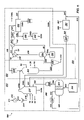
- carbon recovery in a coal-to-liquid hydrocarbon production process 200 may be improved by recycling carbon-containing gas streams in the coal-to-liquid hydrocarbon production process 200 to the coal gasification process 210 .
- carbon dioxide gases separated from the synthesis gas product 243 fed to a Rectisol process 246 may be recycled to the entrained flow gasifier 216 .
- the introduction of additional carbon dioxide into the entrained flow gasifier 216 may result in additional reactions of the carbon dioxide with hydrogen to produce additional carbon monoxide.
- An example of such a process is illustrated in FIG. 4 .
- the second product stream 246 b produced in the Rectisol process 246 contains carbon dioxide. As illustrated in FIG. 4 , the second product stream 246 b may be compressed in compressor 252 and recycled to the entrained flow gasifier 216 , or other gasification equipment, so that the carbon dioxide in the second product stream 246 b may react with hydrogen in the entrained flow gasifier 216 to produce carbon monoxide.
- the ability to redirect the second product stream 246 b from the Rectisol process 246 in the coal-to-liquid hydrocarbon production process 200 illustrated in FIG. 4 is achieved in part because of the integration of the water-splitting process 300 with the coal-to-liquid hydrocarbon production process 200 .
- the elimination of a sour shift reactor from the coal-to-liquid hydrocarbon production process 200 due to the availability of hydrogen 310 from the water-splitting process 300 reduces the size of the second product stream 246 b from the Rectisol process 246 .
- the reduction in the size of the second product stream 246 b allows the second product stream 246 b to be recycled to the coal gasification process 210 . Recycling of the carbon-containing second product stream 246 b improves carbon conversion in the coal-to-liquid hydrocarbon production process 200 and decreases the amount of carbon-based pollutants produced by the process.
- tail gases 291 , light fuel components, or a mixture of tail gases 291 and light fuel components from a Fischer-Tropsch process 260 of a coal-to-liquid hydrocarbon production process 200 may be recycled to the coal gasification process 210 .
- carbon-containing tail gases 291 and any light fuel components may be fed to the entrained flow gasifier 216 , or other gasification unit, to facilitate the conversion of the carbon in the coal to desirable fuel products.
- An example of such recycling is illustrated in FIG. 5 .
- the tail gases 291 from a Fischer-Tropsch process 260 are recycled to the entrained flow gasifier 216 .
- the tail gases 291 may undergo compression in compressor 299 before being fed to the entrained flow gasifier 216 .
- the recycling of the tail gases 291 to the coal gasification process 210 eliminates the tail gas 291 feed for a heat recovery and power generation process 290 in the coal-to-liquid hydrocarbon production process 200 .
- the elimination of the tail gas 291 feed to a heat recovery and power generation process 290 eliminates the need for the heat recovery and generation equipment associated with such processes.
- tail gases 291 may include light hydrocarbons, residual hydrogen, carbon monoxide, water, and carbon dioxide that may be converted into synthesis gas in the coal gasification process 210 .
- While the process illustrated in FIG. 5 includes the recycling of the tail gases 291 from the Fischer-Tropsch process 260 and the second product stream 246 b from the Rectisol process 246 to the entrained flow gasifier 216 , it is understood that the tail gases 291 from the Fischer-Tropsch process 260 may be recycled without recycling the second product stream 246 b to the entrained flow gasifier 216 .
- the recycled tail gases 291 from the Fischer-Tropsch process 260 may include all or only a portion of the total tail gases 291 produced by the Fischer-Tropsch process 260 .
- the second product stream 246 b from the Rectisol process 246 that is recycled to the entrained flow gasifier 216 may include all or only a portion of the second product stream 246 b.
- the recycling of the second product stream 246 b , the tail gases 291 , or a portion or all of the second product stream 246 b and tail gases 291 to the entrained flow gasifier 216 may occur in a process that does not employ a water-splitting process 300 .
- carbon-containing products from the gas cleanup process 130 and from the Fischer-Tropsch process 160 may be recycled to the entrained flow gasifier 116 in a manner similar to that illustrated in FIGS. 4 and 5 .
- the steam generated within the coal-to-liquid hydrocarbon production process 200 may be recovered and combined with heat from one or more nuclear power sources 302 associated with the water-splitting process 300 to superheat the recovered steam and generate electricity according to conventional methods.
- steam recovered from the coal-to-liquid hydrocarbon production process 200 may be utilized or superheated by one or more nuclear power sources 302 or reactors in a water-splitting process 300 associated with the coal-to-liquid hydrocarbon production process 200 .
- the data in Table 2 confirm that the coal-to-liquid hydrocarbon production processes 200 illustrated in FIGS. 3 and 5 produce a greater amount of liquid hydrocarbon fuels for a given amount of coal than does the conventional CTL process 100 illustrated in FIG. 1 .
- the coal-to-liquid hydrocarbon production process 200 illustrated in FIG. 5 produces a greater amount of liquid hydrocarbon fuel as compared to the coal-to-liquid hydrocarbon production process 200 illustrated in FIG. 3 for an equivalent amount of coal.
- the data also indicate that the yield of liquid hydrocarbon fuels produced as a percentage of carbon input into the processes is greatest in the coal-to-liquid hydrocarbon production process 200 illustrated in FIG. 5 .
- the coal-to-liquid hydrocarbon production process 200 illustrated in FIG. 3 is also better at converting carbon to liquid hydrocarbon fuels than is the conventional CTL process 100 illustrated in FIG. 1 .
- the data of Table 2 also provide some insight into the production efficiencies of certain embodiments of the invention.
- the small coal-to-liquid hydrocarbon production process simulated for Table 2 produces the same amount of liquid hydrocarbon fuels as does the conventional CTL process illustrated in FIG. 1 .
- the small coal-to-liquid hydrocarbon production process based upon the configuration of the coal-to-liquid hydrocarbon production process 200 illustrated in FIG. 5 produces the same amount of liquid hydrocarbon fuels as does the conventional CTL process 100 with 5,800 tons of coal per day as compared to the 18,800 tons per day required for the conventional CTL process 100 .
- coal-to-liquid hydrocarbon production processes 200 according to embodiments of the invention are much more efficient at converting coal to hydrocarbon fuels than are conventional processes.
- Table 2 also illustrate the fact that coal-to-liquid hydrocarbon production processes according to particular embodiments of the invention have reduced pollutant emissions as compared to conventional CTL processes 100 .
- the increased yield of liquid fuel based upon the carbon input into each process indicates that the processes illustrated in FIGS. 3 and 5 convert more carbon to liquid fuel than does a conventional process, resulting in less carbon-based pollution from the coal-to-liquid hydrocarbon production process.
- the second product stream 246 b from the Rectisol process 246 may be combined and mixed with the tail gases 291 from the Fischer-Tropsch process 260 as illustrated in FIG. 6 .
- the second product stream 246 b contains carbon dioxide, which may react with the fuel components in the tail gases 291 in a reactor 400 .
- a catalyst may be present in the reactor 400 during the reaction.
- the tail gases 291 from the Fischer-Tropsch process 260 may include hydrocarbons or other liquid fuels, represented by the chemical formula (—CH 2 —).
- the mixing of the carbon dioxide in the second product stream 246 b with the hydrocarbons or fuels in the tail gases 291 may result in a reaction which produces carbon monoxide and hydrogen as shown in Reaction 2:
- the carbon dioxide pollutants in the second product stream 246 b may react with the tail gases 291 from the Fischer-Tropsch process 260 to produce additional carbon monoxide and hydrogen, or syngas, that may be used to produce liquid fuels or liquid hydrocarbons according to embodiments of the invention.
- the second product stream 246 b and the tail gases 291 are clean gas streams that have been previously treated to remove unwanted pollutants. Therefore, the reaction to produce carbon monoxide and hydrogen according to Reaction 2 produces a clean product of carbon monoxide and hydrogen that does not need to be treated to remove pollutants.
- a product 410 containing carbon monoxide and hydrogen formed in the reactor 400 may be recycled and combined with the synthesis gas product 243 fed to the Rectisol process 246 .
- the addition of the product 410 to the synthesis gas product 243 adds additional carbon monoxide and hydrogen to the synthesis gas product 243 , which may be converted to liquid hydrocarbons or other carbon-containing liquid fuels in the Fischer-Tropsch process 260 or other liquid fuel production process.
- the product 410 containing carbon monoxide and hydrogen formed in the reactor 400 may be recycled and combined with the synthesis gas product stream 247 from the Rectisol process 246 .
- the combination of the product 410 and the synthesis gas product stream 247 may be fed to a Fischer-Tropsch process 260 , or other liquid fuel production process, to produce liquid hydrocarbons or other carbon-containing liquid fuels.
- product 410 may be recycled and included in the synthesis gas product 243 or in the synthesis gas product stream 247 , in some embodiments, product 410 may be recycled to both the synthesis gas product 243 and to the synthesis gas product stream 247 .
- the amount of carbon monoxide and hydrogen in product 410 may also be controlled such that the carbon monoxide and hydrogen ratios resulting from the combination of the product 410 with the synthesis gas product 243 , with the synthesis gas product stream 247 , or with both the synthesis gas product 243 and synthesis gas product stream 247 are at a desired ratio.
- the recapture of the waste carbon dioxide separated by the Rectisol process 246 in the liquid fuel production process may improve the total amount of carbon conversion achieved by the coal-to-liquid hydrocarbon production process 200 .
- the conversion of greater amounts of carbon to liquid fuels also decreases the amount of coal or other carbon-containing resource necessary to produce the liquid fuels.
- the ability to recapture carbon dioxide produced by the coal-to-liquid hydrocarbon production process 200 and to convert it into carbon-containing liquid fuels decreases the overall amount of carbon dioxide pollution produced by the coal-to-liquid hydrocarbon production process 200 .
- steam 425 may also be mixed with the second product stream 246 b from the Rectisol process 246 and with tail gases 291 from a Fischer-Tropsch process 260 or other liquid fuel production process.
- steam 425 may be fed to the reactor 400 along with the second product stream 246 b and the tail gases 291 .
- steam 425 may be added directly to the reactor 400 .
- steam 425 may be added to the second product stream 246 b , to the tail gases 291 , or to both the second product stream 246 b and to the tail gases 291 prior to introduction into the reactor 400 .
- steam 425 may be added to the second product stream 246 b and to the tail gases 291 before being introduced into the reactor 400 along with steam 425 introduced directly into the reactor 400 .
- the combination of the second product stream 246 b with steam 425 or the tail gases 291 with steam 425 may be performed in any desired manner.
- the combination of steam 425 with the second product stream 246 b and the tail gases 291 produces water-gas shift reaction and steam reformation of the second product stream 246 b and the tail gases 291 .
- the steam reformation and water-gas shift in the second product stream 246 b and tail gases 291 improve the yield of carbon monoxide and hydrogen from the reaction of the carbon dioxide of the second product stream 246 b with the tail gases 291 and the added steam 425 .
- the improved yield improves the overall performance of the process and the overall conversion of carbon to liquid fuels.
- the use of steam 425 to improve the reaction of carbon dioxide and tail gases 291 to produce carbon monoxide and hydrogen may also produce a desired ratio of carbon monoxide to hydrogen for liquid fuels production.
- the amount of steam 425 added to the second product stream 246 b , to the tail gases 291 , or to the reactor 400 may be tailored to achieve a desired carbon monoxide to hydrogen ratio sufficient for direct feed to a Fischer-Tropsch process 260 or other liquid fuel production process.
- the addition of steam 425 may be controlled to produce a ratio of hydrogen to carbon monoxide in 2.1 to 1.0 molar ratio, which may be optimal for production of liquid fuels in a Fischer-Tropsch process 260 .
- steam 425 may be added to the second product stream 246 b , to the tail gases 291 , or to the reactor 400 for syngas production.
- the amount of steam 425 added may produce a syngas with a H 2 :CO ratio that, when added to the synthesis gas product stream 247 , makes a combined stream with the desired ratio of hydrogen to carbon monoxide.
- Tailgas 7,376 7,376 7,376 7,376 7,376 lbmol/hr CO 2 , lbmol/hr 977 977 977 H 2 O, lbmol/hr — — 8,339 8,339
- Outputs H 2 , lbmol/hr 4,026 9,398 8,150 17,600 CO, lbmol/hr 670 2,227 570 8,426 Soot, lbmol/hr 5,406 6,179 6,991 186 H 2 /CO Ratio 6.00 4.22 14.30 2.09
- steam 425 may be supplied from a renewable energy source.
- a renewable energy source for example, steam 425 produced by a nuclear power plant or by the heat produced by a nuclear reaction, may be combined with the second product stream 246 b or tail gases 291 according to embodiments of the invention.
- steam 425 may be produced by other renewable energy sources, such as by wind power, geothermal power, tidal power, and solar power.
- the use of a renewable or alternative energy source to produce the steam 425 may make up for any heat loss resulting from the recycling of the tail gases 291 rather than the burning of the tail gases 291 as performed in conventional processes, such as that illustrated in FIG. 1 .
- the use of nuclear power to provide the steam 425 requirements of embodiments of the invention may be advantageous especially if the steam 425 is being used with a coal-to-liquid hydrocarbon production process 200 already employing the use of nuclear power.
- hydrogen or oxygen produced by a water-splitting process 300 may be added to the reactor 400 or product 410 produced by the reaction of the second product stream 246 b with the tail gases 291 to alter the composition of the product 410 being recycled to the liquid fuel production process.
- a portion of the second product stream 246 b may be fed to the coal gasification process 210 , such as to an entrained flow gasifier 216 , and the remainder recycled to form product 410 .
- a portion of the tail gases 291 may also be fed to the coal gasification process 210 and the remaining portion recycled to form product 410 or fed to a combustion process.
- a portion of the second product stream 246 b is fed to reactor 400 while a second portion is fed to the coal gasification process 210 .
- a portion of the tail gases 291 are fed to the reactor 400 and a second portion of the tail gases 291 are fed to the coal gasification process 210 .
- the embodiments of the invention may be used with other carbon-conversion processes where carbon-containing products are converted into carbon-containing liquid fuels such as liquid hydrocarbons, methanol, dimethyl ether, and other liquid fuels.
- the product 410 produced in those embodiments illustrated in FIGS. 6 through 8 may be used as a syngas feed to a liquid fuels production process or may be combined with a carbon-containing gas feed stream for conversion in a liquid fuels production process.
- While various embodiments of the invention employ the use of a Fischer-Tropsch process 260 to produce liquid hydrocarbons from a synthesis gas, it is understood that other processes may be used in combination with, or as a substitute for, the Fischer-Tropsch process 260 to produce liquid hydrocarbons, liquid fuel products, or a combination of liquid hydrocarbons and liquid fuel products.
- any processes capable of converting a synthesis gas to liquid hydrocarbons or liquid fuel products may be used in place of, or in combination with, the Fischer-Tropsch process 260 .
- processes having preferred hydrogen to carbon monoxide ratios may be combined with various embodiments of the invention to produce liquid hydrocarbons and liquid fuel products according to the desired ratios.
- synthesis gas conversion processes which produce carbon-containing purge gases may be integrated with various embodiments of the invention to recycle the purge gases to produce additional synthesis gas for conversion to liquid hydrocarbons and liquid fuel products.
- processes that may be substituted for, or combined with, a Fischer-Tropsch process 260 include, but are not limited to, processes for producing methanol or dimethyl ether.
- a water-splitting process 300 with a coal-to-liquid hydrocarbon production process 200 improves the conversion of carbon in coal to liquid hydrocarbon fuels while also reducing the total amount of carbon pollutants produced in such processes.
- water-splitting processes 300 of the present invention include the use of nuclear power sources 302 to provide heat or electricity for the water-splitting process 300
- other power supplies may also be used to operate the electrolyzers 304 .
- nuclear power sources 302 may be substituted or combined with wind power, hydroelectric power, geothermal power, tidal power, or solar power to produce sufficient energy to operate the water-splitting process 300 .
- conventional coal-fired or combustion power plants may be used to supply power to the electrolyzers 304 to generate hydrogen and oxygen for use with coal-to-liquid hydrocarbon production processes 200 according to embodiments of the invention.
- the various coal-to-liquid hydrocarbon production processes 200 may also be scaled up or scaled down to achieve a desired coal consumption rate or hydrocarbon production rate.
- alternative fuels such as carbon-containing fuels, may be used or burned in the coal-to-liquid hydrocarbon production processes 200 to produce synthesis gases.
- fuels that may be used include, but are not limited to, coal, oil shale, biomass, refuse, waste materials, natural gas, lignite, and mixtures thereof.
Landscapes
- Chemical & Material Sciences (AREA)
- Engineering & Computer Science (AREA)
- Oil, Petroleum & Natural Gas (AREA)
- Life Sciences & Earth Sciences (AREA)
- Wood Science & Technology (AREA)
- Chemical Kinetics & Catalysis (AREA)
- General Chemical & Material Sciences (AREA)
- Organic Chemistry (AREA)
- Production Of Liquid Hydrocarbon Mixture For Refining Petroleum (AREA)
- Organic Low-Molecular-Weight Compounds And Preparation Thereof (AREA)
Abstract
Carbon-containing tail gases and pollutants in a coal-to-liquid hydrocarbon production process, or other liquid fuel production process, may be reacted to produce additional synthesis gas which may be used to produce liquid fuels and hydrocarbons or which may be recycled within the liquid fuel production process to improve conversion of carbon to liquid fuels or hydrocarbons.
Description
- This application is a continuation-in-part application of U.S. patent application Ser. No. 11/552,604 filed on Oct. 25, 2006, and entitled “SYNTHETIC FUEL PRODUCTION USING COAL AND NUCLEAR ENERGY,” the disclosure of which is incorporated herein by reference in its entirety.
- The United States Government has certain rights in this invention pursuant to Contract No. DE-AC07-05-ID14517 between the United States Department of Energy and Battelle Energy Alliance, LLC.
- 1. Field of the Invention
- The present invention relates to processes and systems for converting carbonaceous feedstocks to liquid hydrocarbons and liquid fuel products and, more particularly, to the use of alternative energy sources and recycling processes to provide improved recovery in coal-to-liquid or carbon-to-liquid processes and systems.
- 2. State of the Art
- Processes for producing liquid fuel products from coal are well known. One of the more common processes involving the conversion of coal to liquid hydrocarbon fuels involves Fischer-Tropsch processes whereby synthesis gas, or syngas, is converted into liquid fuel products of various forms. Synthesis gas for use in the Fischer-Tropsch process may be produced by the gasification of coal which produces carbon monoxide and hydrogen.
- An example of a conventional coal-to-liquid hydrocarbon process is illustrated in the process flow diagram of
FIG. 1 . The coal-to-liquid hydrocarbon (CTL)process 100 may include a number of sub-processes occurring within theCTL process 100. For example, aconventional CTL process 100 may include acoal gasification process 110, a gas andheat recovery process 120, agas cleanup process 130, a Fischer-Tropschprocess 160, and a heat recovery andpower generation process 190. Each of the sub-processes illustrated inFIG. 1 is separated by dashed lines. - The
coal gasification process 110 of theCTL process 100 includes adryer 112, apulverizer 114, anentrained flow gasifier 116, and anair separation unit 118.Coal 111 for use in thecoal gasification process 110 is fed to one ormore dryers 112 to reduce moisture in thecoal 111. Moisture extracted from thecoal 111 may be discharged from thedryers 112. Adryer 112 may include a heat exchanger or other conventional drying process typically used withCTL processes 100. The driedcoal 113 is fed to apulverizer 114 where the driedcoal 113 is pulverized, crushed, or otherwise reduced to a sufficient size for coal gasification. The pulverizedcoal 115 is fed to the entrainedflow gasifier 116 where the coal is gasified.Air 119 fed to theair separation unit 118, such as a cryogenic air separation unit, is converted into nitrogen (N2) and oxygen (O2). The nitrogen is purged asnitrogen stream 118 b while the oxygen stream 118 a is fed to the entrainedflow gasifier 116. - The pulverized
coal 115 fed to the entrainedflow gasifier 116 is gasified with oxygen from the oxygen stream 118 a in the presence ofsteam 50 fed to the entrainedflow gasifier 116. Boiler feed water (BFW) 52 may also be fed to the entrained flow gasifier to absorb heat produced in the gasification process, forming a medium pressure steam (MPS) 54 which may be removed from the entrainedflow gasifier 116 and used elsewhere in theCTL process 100. The combustion, pyrolysis, and gasification of the pulverizedcoal 115 fed to the entrainedflow gasifier 116 produces asyngas product 116 a and aslag 116 b. Thesyngas product 116 a is removed from the entrainedflow gasifier 116 and thecoal gasification process 110 and is fed to a gas andheat recovery process 120.Slag 116 b is removed from the entrainedflow gasifier 116 and is disposed of or otherwise utilized according to conventional methods. - The
syngas product 116 a from the entrainedflow gasifier 116 includes carbon monoxide (CO), hydrogen (H2), and other gas products. Thehot syngas product 116 a is fed to asyngas cooler 122 in the gas andheat recovery process 120. Thesyngas cooler 122 cools thehot syngas product 116 a and produces acool syngas product 123 which is withdrawn from thesyngas cooler 122. Thecool syngas product 123 is then fed to agas cleanup process 130. - The
hot syngas product 116 a fed to thesyngas cooler 122 may also be combined with aquench gas 143 from thegas cleanup process 130, the quench gas having been fed through one ormore compressors 124. -
Boiler feed water 52 may also be fed to thesyngas cooler 122. Theboiler feed water 52 absorbs heat within thesyngas cooler 122 producing steam, such ashigh pressure steam 56 andmedium pressure steam 54.High pressure steam 56 produced in thesyngas cooler 122 is discharged.High pressure steam 56 may also be fed to thesour shift reactor 138 of thegas cleanup process 130.Medium pressure steam 54 produced in thesyngas cooler 122 may be recovered and used elsewhere in theCTL process 100. - The
gas cleanup process 130 is used to remove pollutants and other unwanted products from thecool syngas product 123 fed to thegas cleanup process 130. Thegas cleanup process 130 includes acyclone 132, awater scrubber 134, ablack water system 136, asour shift reactor 138, aheat exchanger 140, acondenser 142, and an activated carbon bed 144. Thegas cleanup process 130 also includes equipment for removing hydrogen sulfide (H2S) and carbon dioxide (CO2) from synthesis gas. -
Cool syngas product 123 fed to thegas cleanup process 130 is fed to acyclone 132 to removeflash 133 and other particulates from thecool syngas product 123. Thecool syngas product 123 is then fed to awater scrubber 134 withwater 60. Thewater scrubber 134 removes pollutants and other impurities from thecool syngas product 123 and discharges the removed pollutants and other impurities withwater 60 in awaste water stream 134 a. Ascrubbed syngas product 135 is split into a firstscrubbed syngas stream 135 a that is fed to thesour shift reactor 138 and a secondscrubbed syngas stream 135 b that bypasses thesour shift reactor 138 and is combined with the shiftedsyngas product 138 a from thesour shift reactor 138. The firstscrubbed syngas stream 135 a fed to thesour shift reactor 138 is combined withhigh pressure steam 56 fed to thesour shift reactor 138 to produce desired ratios of hydrogen and carbon monoxide for the syngas being produced. The shift of the hydrogen and carbon monoxide ratios in the shiftedsyngas product 138 a from thesour shift reactor 138 may be manipulated such that the combination of the shiftedsyngas product 138 a with the secondscrubbed syngas product 135 b produces asyngas product 139 having a desired ratio of hydrogen and carbon monoxide for the Fischer-Tropschprocess 160. - The
waste water stream 134 a is fed to a blackwater treatment system 136 for treatment of thewaste water stream 134 a according to conventional methods. - The
syngas product 139 is fed to aheat exchanger 140 that cools thesyngas product 139.Boiler feed water 52 fed to theheat exchanger 140 may be converted intomedium pressure steam 54, which may be used in other portions of theCTL process 100. - The cooled
syngas product 141 from theheat exchanger 140 is fed to acondenser 142 wherewater 60 in the cooledsyngas product 141 is condensed and removed from the cooledsyngas product 141. Thewater 60 may be fed to thewater scrubber 134 in thegas cleanup process 130. - The
syngas product 143 from thecondenser 142 is fed to an activated carbon bed 144. The activated carbon bed 144 removes unwanted mercury pollutants from thesyngas product 143. A portion of thesyngas product 143 exiting the activated carbon bed 144 may be removed and fed to thecompressor 124 of the gas andheat recovery process 120 and combined with thesyngas product 116 a as feed stock to thesyngas cooler 122. The remainder of thesyngas product 143 is fed to aRectisol process 146 to further remove hydrogen sulfide (H2S) and carbon dioxide (CO2) from thesyngas product 143. - The
Rectisol process 146 removes hydrogen sulfide and carbon dioxide from thesyngas product 143, producing afirst product stream 146 a containing hydrogen sulfide and carbon dioxide, asecond product stream 146 b containing carbon dioxide, apurge gas 146 c, and asyngas product stream 147. - The
first product stream 146 a can be fed to aClaus process 148 for removal ofsulfur 148 a from the gaseous hydrogen sulfide in thefirst product stream 146 a. TheClaus tail gases 148 b are fed to aSCOT process 150 for further treatment before being discharged as a SCOTprocess purge gas 150 a. - The
second product stream 146 b of carbon dioxide is compressed in afirst compressor 152 and then fed to a triethylene glycol (TEG)dehydration process 154 where water is removed from thesecond product stream 146 b. Water removed from thesecond product stream 146 b may be used elsewhere in theCTL process 100. Carbon dioxide gas from theTEG process 154 is fed to acompressor 156 where it is cooled to formliquid carbon dioxide 157. Theliquid carbon dioxide 157 is pumped to a storage tank or other process for further use. - The
purge gas 146 c from theRectisol process 146 is released into the environment. TheRectisol process 146,Claus process 148,SCOT process 150, andTEG dehydration process 154 are well known processes conventionally used to remove sulfur and carbon dioxide pollutants from CTL processes 100. - The
syngas product stream 147 is fed to a Fischer-Tropsch process 160 for conversion of thesyngas product stream 147 into liquid fuel products. The Fischer-Tropsch process 160 illustrated inFIG. 1 includes a first Fischer-Tropsch reactor 162, afirst heat exchanger 164, afirst separation unit 166, acompressor 168, a second Fischer-Tropsch reactor 172, asecond heat exchanger 174, asecond separation unit 176, ahydrocracker 170, ahydrogen separation membrane 178, asecond compressor 180, atank 182, anddistillation columns 184. - The
syngas product stream 147 from thegas cleanup process 130 contains hydrogen (H2) and carbon monoxide (CO). In the Fischer-Tropsch process 160, thesyngas product stream 147 is fed to the first Fischer-Tropsch reactor 162 where the hydrogen and carbon monoxide in thesyngas product stream 147 are converted into liquid fuel products through a catalysis reaction, such as Reaction 1: -
(2n+1)H2 +nCO→CnH2n+2 +nH2O (1), - where n may be between about 1 and about 42, although n may also be greater than 42. For example, for light hydrocarbons n may be between about 1 and about 7, for intermediate hydrocarbons n may be from about 8 to about 13, and for heavy hydrocarbons n may be above about 14.
- A
first hydrocarbon stream 163 containing both liquid fuel products and gas from the first Fischer-Tropsch reactor 162 is cooled in thefirst heat exchanger 164.Boiler feed water 52 fed to thefirst heat exchanger 164 absorbs heat from thefirst hydrocarbon stream 163, producingmedium pressure steam 54 that is purged for use in other processes. The cooledfirst hydrocarbon stream 163 is fed to thefirst separation unit 166 where various constituents of the first-hydrocarbon stream 163 are separated.Syngas 167 remaining in thefirst hydrocarbon stream 163 is separated by thefirst separation unit 166 and purged to be fed to the second Fischer-Tropsch reactor 172. The liquid fuel products in thefirst hydrocarbon stream 163 are separated by thefirst separation unit 166 into two hydrocarbon streams: a firstlight hydrocarbon product 166 a containing intermediate distillates and light hydrocarbons, and a firstheavy hydrocarbon product 166 b containing heavy hydrocarbons. Thefirst separation unit 166 also removeswater 60 from thefirst hydrocarbon stream 163 and purges thewater 60 from the other products. -
Syngas 167 from thefirst separation unit 166 is compressed in thecompressor 168 and is then fed to the second Fischer-Tropsch reactor 172 where thesyngas 167 is catalytically reacted to convert the hydrogen and carbon monoxide in thesyngas 167 into liquid fuel products. For example, thesyngas 167 may be converted into liquid fuel products in accordance with Reaction 1. Asecond hydrocarbon stream 173 from the second Fischer-Tropsch reactor 172 is cooled in thesecond heat exchanger 174 and fed to thesecond separation unit 176.Boiler feed water 52 fed to thesecond heat exchanger 174 absorbs heat from thesecond hydrocarbon stream 173, producingmedium pressure steam 54 that is purged for use in other processes or other parts of theCTL process 100. - The
second separation unit 176 separates thesecond hydrocarbon stream 173 into its various constituents.Water 60 separated from thesecond hydrocarbon stream 173 is purged from thesecond separation unit 176 for use elsewhere. Liquid fuel products in thesecond hydrocarbon stream 173 are separated into two hydrocarbon streams: a secondlight hydrocarbon product 176 a containing intermediate distillates and light hydrocarbons, and a secondheavy hydrocarbon product 176 b containing heavy hydrocarbons. Thetail gases 177 separated from thesecond hydrocarbon stream 173 in thesecond separation unit 176 are fed to thehydrogen separation membrane 178 where the hydrogen (H2) 179 in thetail gases 177 is removed. - Heavy hydrocarbons produced in the Fischer-
Tropsch process 160 are converted to light hydrocarbons or liquid fuel products in thehydrocracker 170. The firstheavy hydrocarbon product 166 b and the secondheavy hydrocarbon product 176 b produced by the Fischer-Tropsch reactors are mixed together to form aheavy hydrocarbon stream 169 that is fed to thehydrocracker 170.Heavy hydrocarbons 185 from thedistillation column 184 are also fed to thehydrocracker 170.Hydrogen 179, separated from thetail gases 177 by thehydrogen separation membrane 178, is pressurized or compressed incompressor 180 before being fed to thehydrocracker 170 to facilitate the hydrocracking of the heavy hydrocarbons to produce ahydrocarbon product 171 of lighter hydrocarbons or liquid fuel products from thehydrocracker 170. - The
hydrocarbon product 171 is combined with the secondlight hydrocarbon product 176 a and then with the firstlight hydrocarbon product 166 a and mixed intank 182 to form alight hydrocarbon product 183. Thelight hydrocarbon product 183 is fed to thedistillation column 184. Within thedistillation column 184, thelight hydrocarbon product 183 produced by the Fischer-Tropsch process 160 is distilled intonaphtha products 186 anddiesel products 187.Heavy hydrocarbons 185 produced in thedistillation column 184 are removed from thedistillation column 184 and fed to thehydrocracker 170. Purgegases 188 from thedistillation column 184 may be combined with thetail gases 177 and fed to thehydrogen separation membrane 178 for separation of hydrogen from thepurge gases 188. - The
CTL process 100 may also include a heat recovery andpower generation process 190. The heat recovery andpower generation process 190 converts heat recovered from theCTL process 100 into power.Recovered steam 58, such ashigh pressure steam 56 andmedium pressure steam 54, collected in theCTL process 100 is fed to a heatrecovery steam generator 194 along withboiler feed water 52 andair 119.Tail gases 191 from thehydrogen separation membrane 178 are combined withair 119 and burned in agas turbine 192 connected to a generator to produce electricity.Exhaust gases 193 from thegas turbine 192 are fed to the heatrecovery steam generator 194 to further heat theboiler feed water 52 and recoveredsteam 58 fed to the heatrecovery steam generator 194.Superheated steam 195 produced in the heatrecovery steam generator 194 is fed to a condensingsteam turbine 196 which produces electricity from the expansion and cooling of thesuperheated steam 195. The water produced in the condensingsteam turbine 196 is fed to apump 199 and pumped throughout theCTL process 100 to be used as boiler feedwater 52. - The
exhaust gases 193 are cooled in the heatrecovery steam generator 194 and are then fed to astack 198. The gases exiting the stack may be further treated or released into the environment. - Although CTL processes 100 such as the one illustrated in
FIG. 1 may be used to produce liquid hydrocarbons and liquid fuel products from synthesis gas produced by the gasification of coal, such processes often produce a larger amount of pollutants than do conventional petroleum extraction and refining processes associated with liquid fuel production. One of the most prevalent pollutants produced by coal gasification is carbon dioxide (CO2). Increased production of synthesis gases from coal gasification to supply Fischer-Tropsch processes with sufficient synthesis gas to produce liquid hydrocarbons and liquid fuel products would result in the unwanted increased production of carbon dioxide emissions. Proposals to counter the increased carbon dioxide emissions resulting from coal gasification have included proposals to sequester the carbon dioxide or otherwise convert the carbon dioxide produced in such a process prior to release into the environment. Carbon dioxide sequestration processes are expensive and add additional costs to liquid hydrocarbon production processes. Other proposed alternatives to encourage sequestration or conversion of carbon dioxide to a non-pollutant have also been made, including proposals to tax carbon dioxide emissions from coal gasification and Fischer-Tropsch processes. - Furthermore, coal gasification processes tend to be fairly inefficient. For example, a
CTL process 100 such as that illustrated inFIG. 1 may convert about thirty-percent of the carbon contained in the coal fed to the process to liquid hydrocarbons or liquid fuel products. The remaining seventy-percent of the carbon in the coal is converted to carbon dioxide, other pollutants, or solid wastes that must be disposed. - Therefore, it would be desirable to improve the efficiency of coal-to-liquid hydrocarbon production process and to increase the conversion of carbon obtained from coal to liquid fuel products. It would also be desirable to decrease the carbon dioxide emissions of coal-to-liquid hydrocarbon production processes.
- According to embodiments of the invention, the conversion of carbon to liquid fuel products in a coal-to-liquid hydrocarbon production process may be improved by modifying a conventional coal-to-liquid hydrocarbon production process or by incorporating the modifications into new process plants. The modifications to a coal-to-liquid hydrocarbon production process facilitate the conversion of carbon to liquid fuel products and reduce the amount of carbon-based pollutants produced by a coal-to-liquid hydrocarbon production process.
- In some embodiments of the invention, a water-splitting process, such as an electrolysis or thermochemical process, for producing oxygen may be integrated with a liquid fuel production process, such as a coal-to-liquid hydrocarbon production process, or may be configured to supply oxygen to a liquid fuel production process. The oxygen may be used in the liquid fuel production process to gasify coal in the production of a synthesis gas containing hydrogen and carbon monoxide. The water-splitting process may produce oxygen from water utilizing conventional electrolysis processes. The power or heat required by the water-splitting process to produce oxygen from water may be supplied from a nuclear power source. The use of a nuclear power source to produce electricity or power to supply to the water-splitting process decreases the production of pollutants associated with conventional coal-fired electricity generation operations. The resulting liquid fuel production process therefore produces fewer pollutants. In addition, the use of a water-splitting process reduces the need for air separation units conventionally used with gasification processes to produce oxygen, reducing the equipment and operating costs associated with the production of liquid fuels, such as by the gasification of coal.
- In other embodiments of the invention, the water-splitting process may also produce hydrogen. The water-splitting process may be configured to supply the produced hydrogen to the liquid fuel production process. In particular, hydrogen produced by the water-splitting process may be mixed with synthesis gas produced in the liquid fuel production process to achieve a desired ratio of hydrogen to carbon monoxide in the synthesis gas. The hydrogen produced by the water-splitting process may also be used to facilitate hydrocracking of heavy hydrocarbons or liquid fuel products produced from the synthesis gas generated in the liquid fuel production process.
- The incorporation of a hydrogen-producing water-splitting process with a liquid fuel production process also allows for the reduction of equipment needed in a liquid fuel production process. The availability of hydrogen to mix with synthesis gas produced in the process reduces or eliminates the need for shift reactions within the liquid fuel production process. Therefore, equipment associated with such shift reactions may be made smaller or removed from the process, reducing the overall equipment and operational costs of the process.
- According to still other embodiments of the invention, pollutant gases removed from the synthesis gases produced in a liquid fuel production process may be recycled to a coal gasification process or other synthesis gas production process. Carbon-containing compounds and pollutants, such as carbon dioxide, carbon monoxide, methane, alkanes, alkenes, alcohols, aldehydes, or other species, produced in a liquid fuel production process may be recycled to a coal gasification process, for example, where the carbon-containing pollutants may be further reacted to produce additional synthesis gas. The production of additional synthesis gas from the carbon-containing pollutants improves the yield of liquid hydrocarbons and liquid fuel products produced in the process while reducing the amount of carbon-containing pollutants produced by the process.
- According to other particular embodiments of the invention, tail gases from a Fischer-Tropsch process associated with a liquid fuel production process, such as a coal-to-liquid hydrocarbon production process, may be recycled to generate additional synthesis gas in the process. In some embodiments, the tail gases may be recycled because they are not needed to supply energy due to the availability of an alternative energy source, such as a nuclear reactor.
- According to other embodiments of the invention, tail gases from a Fischer-Tropsch process associated with a liquid fuel production process may be reacted with carbon dioxide removed from a synthesis gas produced by a carbon-containing fuel gasification process. The reaction of the tail gases with the carbon dioxide may produce carbon monoxide and hydrogen which may be recycled and combined with synthesis gas produced by a gasification process, recycled and combined with a cleaned synthesis gas, or recycled to a Fischer-Tropsch process or other liquid fuel production process. In some embodiments of the invention, steam may be combined with the tail gas, with the carbon dioxide, or with both the tail gas and carbon dioxide prior to or during the reaction of the tail gas and carbon dioxide. The inclusion of steam in the reaction of the carbon dioxide and the tail gas may improve the production of carbon monoxide and hydrogen or may alter the amounts of carbon monoxide and hydrogen produced by the reaction.
- In still other embodiments of the invention, at least a portion of the reaction product of carbon monoxide and hydrogen produced by the reaction of tail gases from a liquid fuel production process may be recycled to a gas cleanup process. Alternatively, the reaction product may be mixed with a product gas from a gasification process. The recycling of the carbon monoxide and hydrogen to the gasification process may improve the conversion of the carbon in the carbon-containing fuel into useful synthesis gas products rather than pollutants or unwanted products.
- The liquid fuel production processes of various embodiments of the invention provide enhanced yields of liquid hydrocarbons and liquid fuel products per ton of coal or fuel when compared to conventional processes. In addition, the liquid fuel production processes of embodiments of the invention reduce the production of carbon-containing pollutants in the process.
- While the specification concludes with claims particularly pointing out and distinctly claiming that which is regarded as the present invention, this invention can be more readily understood and appreciated by one of ordinary skill in the art from the following description of the invention when read in conjunction with the accompanying drawings in which:
-
FIG. 1 illustrates a process flow and system diagram of a conventional coal-to-liquid hydrocarbon production process; -
FIG. 2 illustrates a process flow and system diagram of a coal-to-liquid hydrocarbon production process according to certain embodiments of the invention; -
FIG. 3 illustrates a process flow and system diagram of a coal-to-liquid hydrocarbon production process according to certain embodiments of the invention; -
FIG. 4 illustrates a process flow and system diagram of a coal-to-liquid hydrocarbon production process according to certain embodiments of the invention; -
FIG. 5 illustrates a process flow and system diagram of a coal-to-liquid hydrocarbon production process according to certain embodiments of the invention; -
FIG. 6 illustrates a process flow and system diagram of a liquid fuel production process according to certain embodiments of the invention; -
FIG. 7 illustrates a process flow and system diagram of a liquid fuel production process according to certain embodiments of the invention; and -
FIG. 8 illustrates a process flow and system diagram of a liquid fuel production process according to certain embodiments of the invention. - According to embodiments of the invention, a nuclear power source may be integrated with or incorporated into a liquid fuel production process, such as a coal-to-liquid hydrocarbon production process, to facilitate the production of hydrocarbons and liquid fuel products from coal. Although the additional heat produced by a nuclear power source may not be needed in a conventional coal-to-liquid hydrocarbon production process, the integration of a nuclear power source with a coal-to-liquid hydrocarbon production process, or other liquid fuel production process, facilitates the use of alternative processes to produce oxygen (O2) and hydrogen (H2), allowing expensive equipment to be removed from a liquid fuel production process.
- While various embodiments of the invention may be integrated with liquid fuel production processes, many of the embodiments will be described with respect to a coal-to-liquid hydrocarbon production process. It is understood that other liquid fuel production processes may be substituted for the coal-to-liquid hydrocarbon production processes described with respect to particular embodiments of the invention.
- According to certain embodiments of the invention, a nuclear power source may be configured to provide electric power, heat, or a combination of electric power and heat to operate a water-splitting process. The water-splitting process may be used to generate oxygen and hydrogen from water. Oxygen produced by the water-splitting process may be substituted for the oxygen produced by an
air separation unit 118 in aconventional CTL process 100 such as the process illustrated inFIG. 1 . The alternative source of oxygen provided by the water-splitting process and nuclear power source eliminates the need for an air separation unit in aCTL process 100. Air separation units, such asair separation unit 118 in theconventional CTL process 100 illustrated inFIG. 1 , are often expensive to install and expensive to operate. The use of oxygen from a water-splitting process operated with nuclear power may therefore decrease the costs associated with the operation of a coal-to-liquid hydrocarbon production process. - An example of a coal-to-liquid
hydrocarbon production process 200 utilizing oxygen produced by a water-splitting process 300 rather than by an air separation unit is illustrated inFIG. 2 . As with aconventional CTL process 100, coal-to-liquidhydrocarbon production processes 200 may include sub-processes such as acoal gasification process 210, a gas andheat recovery process 220, agas cleanup process 230, a Fischer-Tropsch process 260, and a heat recovery andpower generation process 290. The sub-processes of the coal-to-liquidhydrocarbon production process 200 which do not differ fromconvention CTL process 100 sub-processes are illustrated as sub-process blocks inFIG. 2 . - The coal-to-liquid
hydrocarbon production process 200 illustrated inFIG. 2 may also include a water-splitting process 300. For example, a water-splitting process 300 may include an electrolysis process or a thermochemical water-splitting process. While various water-splitting processes may be used with various embodiments of the invention, certain embodiments are described with respect to the use of an electrolysis process. It is understood that other water-splitting processes may be used in place of or in combination with an electrolysis process according to various embodiments of the invention. For example, a water-splitting process 300 according to embodiments of the invention may include one or morenuclear power sources 302, one ormore electrolyzers 304, one ormore oxygen compressors 312, and one ormore hydrogen compressors 314. - The one or more
nuclear power sources 302 may include any source of power resulting from nuclear energy. For example, multiple high-temperature nuclear reactors may be used to produceelectricity 303 capable of operating one ormore electrolyzers 304 to produceoxygen 308 andhydrogen 310 fromwater 306. Theoxygen 308 may be compressed by one ormore compressors 312 and fed to the entrainedflow gasifier 216 of thecoal gasification process 210. The introduction ofoxygen 308 from theelectrolyzers 304 into the entrainedflow gasifier 216 eliminates the need for an oxygen supply from an air separation unit. -
Electrolyzers 304 may includeconventional electrolyzers 304 such as electrolyzers used in conventional low temperature electrolysis, high temperature electrolysis, or thermochemical processes. - According to particular embodiments of the invention,
coal 211 for use in thecoal gasification process 210 may be fed to one ormore dryers 212 to reduce moisture in thecoal 211. The one ormore dryers 212 may include heat exchangers or other conventional drying processes. The driedcoal 213 may be fed to apulverizer 214 where the driedcoal 213 is pulverized, crushed, or otherwise reduced to a sufficient size for coal gasification. The pulverizedcoal 215 may be fed to an entrainedflow gasifier 216 to gasify the pulverizedcoal 215.Oxygen 308 orcompressed oxygen 308 from theelectrolysis process 300 is also fed to the entrainedflow gasifier 216 to facilitate gasification of coal within the entrainedflow gasifier 216.Steam 50 and boiler feedwater 52 may also be fed to the entrainedflow gasifier 216. The gasification of coal within the entrainedflow gasifier 216 produces asynthesis gas product 216 a, or syngas, comprising hydrogen and carbon monoxide.Slag 216 b produced in the entrainedflow gasifier 216 may be removed from the entrainedflow gasifier 216 and disposed of as desired. Heat generated in the entrainedflow gasifier 216 may be used to producemedium pressure steam 54 from theboiler feed water 52 introduced to the entrainedflow gasifier 216. Themedium pressure steam 54 produced by the entrainedflow gasifier 216 may be used elsewhere in the coal-to-liquidhydrocarbon production process 200 as desired. - While the coal gasification processes 210 of the coal-to-liquid hydrocarbon production processes 200 described in various embodiments of the invention utilize entrained
flow gasifiers 216 to gasify coal, it is understood that other gasification units may be substituted for the entrainedflow gasifiers 216. For example, gasification units that may be used with coal gasification processes 210 of the various embodiments of the invention may include, but are not limited to, entrained flow gasifiers, counter-current fixed bed gasifiers, co-current fixed bed gasifiers, and fluid bed gasifiers. Other coal gasification equipment capable of producing a synthesis gas from the gasification of coal could also be used as a gasification unit. - The entrained
flow gasifier 216, or other gasification equipment, may be configured to gasify coal at a desired temperature. In certain embodiments, for example, the entrainedflow gasifier 216 may operate within a temperature range of between about 1300° C. and about 1600° C. Operation within such a temperature range may reduce the formation of carbon dioxide (CO2) and methane (CH4) within the entrainedflow gasifier 216. - The
synthesis gas product 216 a from thecoal gasification process 210 may be fed to a gas andheat recovery process 220 which produces asynthesis gas product 223 that may be fed to agas cleanup process 230. Thegas cleanup process 230 removes pollutants such as hydrogen sulfide (H2S) and carbon dioxide (CO2) from thesynthesis gas product 223. For example, processes such as Rectisol processes, Claus processes, SCOT processes, and TEG dehydration processes may be used to remove pollutants from thesynthesis gas product 223. The cleaned synthesis gas from thegas cleanup process 230 may be fed to a Fischer-Tropsch process 260 as asyngas product stream 247. The Fischer-Tropsch process 260 may convert thesyngas product stream 247 intonaphtha products 286 anddiesel products 287.Tail gases 291 from the Fischer-Tropsch process 260 may be fed to a heat recovery andpower generation process 290 to produce electricity. - According to other embodiments of the invention, hydrogen produced by a water-
splitting process 300 in a coal-to-liquidhydrocarbon production process 200 may be added to synthesis gas produced in the coal-to-liquidhydrocarbon production process 200. As illustrated inFIG. 3 ,hydrogen 310 produced by one ormore electrolyzers 304 in a water-splitting process 300 may be compressed by one ormore compressors 314 and combined with a synthesisgas product stream 247 being fed to a Fischer-Tropsch process 260 of a coal-to-liquidhydrocarbon production process 200. The addition ofhydrogen 310 to the synthesisgas product stream 247 may be used to obtain a desired ratio of hydrogen to carbon monoxide within the synthesisgas product stream 247. For example, in some coal-to-liquidhydrocarbon production processes 200 according to embodiments of the invention, the synthesis gas fed to the Fischer-Tropsch process 260 may have a hydrogen to carbon monoxide mole ratio (H2/CO) of about 2.15. The ability to supplement the synthesisgas product stream 247 with hydrogen from the water-splitting process 300 allows the H2/CO ratio of the Fischer-Tropsch process 260 feed gas to be tailored or configured as desired. - The addition of
hydrogen 310 to the synthesisgas product stream 247 may also reduce or eliminate the need for water-gas shift chemistry in agas cleanup process 230, which removes the need for the inclusion of a sour shift reactor in the coal-to-liquidhydrocarbon production process 200. Instead of including equipment within the coal-to-liquidhydrocarbon production process 200 to shift the ratio of hydrogen to carbon monoxide in a synthesisgas product stream 247,hydrogen 310 produced in a water-splitting process 300 may be combined with the synthesisgas product stream 247 to achieve the desired ratios of hydrogen and carbon dioxide for a Fischer-Tropsch process 260. - One configuration for particular embodiments of the invention is illustrated in
FIG. 3 . Asynthesis gas product 216 a from thecoal gasification process 210 may be introduced into asyngas cooler 222 of a gas andheat recovery process 220 of the coal-to-liquidhydrocarbon production process 200. Thesyngas cooler 222 cools the hotsynthesis gas product 216 a and produces a coolsynthesis gas product 223 which is withdrawn from thesyngas cooler 222 and fed to thegas cleanup process 230.Boiler feed water 52 fed to thesyngas cooler 222 may absorb heat from the hotsynthesis gas product 216 a fed to thesyngas cooler 222, resulting in the production ofhigh pressure steam 56 andmedium pressure steam 54 which are removed from thesyngas cooler 222 for use elsewhere in the coal-to-liquidhydrocarbon production process 200. - The
syngas cooler 222 may include conventional equipment for cooling gases produced in acoal gasification process 210. For example, thesyngas cooler 222 may include one or more convective syngas coolers, radiant syngas coolers, or a combination of convective and radiant syngas coolers. - The
synthesis gas product 223 may be fed to agas cleanup process 230. The gas cleanup process may include acyclone 232, awater scrubber 234, a blackwater treatment system 236, aheat exchanger 240, acondenser 242, an activatedcarbon bed 244, aRectisol process 246, aClaus process 248, aSCOT process 250, aTEG dehydration process 254, and one ormore compressors TEG dehydration process 254. While thegas cleanup process 230 illustrated inFIG. 3 includes single pieces of equipment utilized in the process, multiple pieces of equipment may also be used. For example, theheat exchanger 240 may be replaced by two ormore heat exchangers 240 as desired. Scaling of thegas cleanup process 230 in order to accommodate desired product flows is feasible. -
Fly ash 233 and other particulates entrained in thesynthesis gas product 223 fed to thecyclone 232 may be removed from thecyclone 232 and the synthesis gas product may be fed to awater scrubber 234.Water 60 fed to thewater scrubber 234 removes pollutants and other impurities from thesynthesis gas product 223 and discharges thewater 60 and other impurities aswaste water stream 234 a which may be fed to a blackwater treatment system 236 or other treatment system to treat thewaste water stream 234 a. A scrubbedsynthesis gas product 239 from thewater scrubber 234 may be fed to aheat exchanger 240 to cool the scrubbedsynthesis gas product 239.Boiler feed water 52 fed to theheat exchanger 240 may absorb heat from the scrubbedsynthesis gas 239, producing steam such as amedium pressure steam 54 that may be used elsewhere in the coal-to-liquidhydrocarbon production process 200. The cooled, scrubbedsynthesis gas product 241 may be fed to acondenser 242 wherewater 60 in the cooled, scrubbedsynthesis gas product 241 is recovered. Thesynthesis gas product 243 exiting thecondenser 242 may then be treated to further remove pollutants from thesynthesis gas product 243. - Mercury in the
synthesis gas product 243 may be removed by contacting thesynthesis gas product 243 with activated carbon in an activatedcarbon bed 244. Thesynthesis gas product 243 exiting the activatedcarbon bed 244 may be fed to one or more processes for removing hydrogen sulfide and carbon dioxide from thesynthesis gas product 243. In addition, a portion of thesynthesis gas product 243 may be diverted to acompressor 224 and then mixed withsynthesis gas product 216 a from thecoal gasification process 210. In some embodiments, a portion of thesynthesis gas product 243 exiting thecondenser 242 may be diverted to acompressor 224 rather than being fed to the activatedcarbon bed 244. This diversion may be in combination with or in place of the diversion of the portion ofsynthesis gas product 243 exiting the activatedcarbon bed 244. - As illustrated in
FIG. 3 , at least a portion of thesynthesis gas product 243 may be fed to aRectisol process 246 to remove hydrogen sulfide (H2S) and carbon dioxide (CO2) from thesynthesis gas product 243. TheRectisol process 246 may produce afirst product stream 246 a containing hydrogen sulfide and carbon dioxide, asecond product stream 246 b containing carbon dioxide, apurge gas 246 c, and a synthesisgas product stream 247. - The
first product stream 246 a may be further treated by aClaus process 248 and aSCOT process 250 to remove sulfur and carbon dioxide pollutants from thefirst product stream 246 a and to producetail gases 250 a that are sufficiently clean to be released into the environment. A sulfur product 248 a may be discharged from theClaus process 248. - The
second product stream 246 b may be compressed incompressor 252 and treated with aTEG dehydration process 254 to purify carbon dioxide from thesecond product stream 246 b. Carbon dioxide gas removed from thesecond product stream 246 b may be fed to acompressor 256 and cooled to formliquid carbon dioxide 257. Theliquid carbon dioxide 257 may be pumped with apump 258 to a storage container or other process as desired. Thus, carbon dioxide pollutants recovered from thesynthesis gas product 243 may be converted to liquid carbon dioxide for use or sale. - The
purge gas 246 c from theRectisol process 246 may be released into the environment. Rectisol processes 246, Claus processes 248, SCOT processes 250 and TEG dehydration processes 254 are well known processes and conventional equipment may be readily utilized to carry out such processes in thegas cleanup process 230 of the coal-to-liquidhydrocarbon production processes 200 according to embodiments of the invention may be readily utilized. - The synthesis
gas product stream 247 produced by thegas cleanup process 230 may be fed to one or more Fischer-Tropsch processes 260 where the synthesisgas product stream 247 is converted intonaphtha products 286 anddiesel products 287. According to embodiments of the invention,hydrogen 310 from a water-splitting process 300 may be mixed with the synthesisgas product stream 247 prior to or at the same time that the synthesisgas product stream 247 is fed to the Fischer-Tropsch process 260. The addition ofhydrogen 310 to the synthesisgas product stream 247 may be controlled to achieve a desired ratio of hydrogen and carbon monoxide being fed to the Fischer-Tropsch process 260. -
Tail gases 291 from the Fischer-Tropsch process 260 may be fed to a heat recovery andpower generation process 290 if desired. - Although the coal-to-liquid
hydrocarbon production process 200 illustrated inFIG. 3 includes the use of both thehydrogen 310 andoxygen 308 produced by the water-splitting process 300 in the coal-to-liquidhydrocarbon production process 200, it is understood that various embodiments of the invention may also utilize just theoxygen 308 produced by theelectrolyzers 304 as a feed stream to thecoal gasification process 210 as illustrated inFIG. 2 , or just thehydrogen 310 produced by theelectrolyzers 304 as a synthesisgas product stream 247 additive. - In still other embodiments of the invention,
hydrogen 310 produced by a water-splitting process 300 may be fed to a Fischer-Tropsch process 260 and combined with hydrogen produced by a hydrogen membrane of the Fischer-Tropsch process 260 (not shown). For example,hydrogen 310 produced by the water-splitting process 300 may be used with hydrocracking and hydrotreating processes of a Fischer-Tropsch process 260. - In other embodiments of the invention,
hydrogen 310 produced by a water-splitting process 300 may be fed to agasifier 216 as illustrated inFIG. 3 .Hydrogen 310 fed to agasifier 216 may assist in the conversion of carbon dioxide to carbon monoxide when carbon dioxide is formed in thegasifier 216 or recycled to thegasifier 216. - The combination of a water-
splitting process 300 with a coal-to-liquidhydrocarbon production process 200 as illustrated inFIGS. 2 and 3 offers many advantages over conventional coal-to-liquid hydrocarbon production processes. For example, as illustrated inFIG. 2 , the use ofoxygen 308 produced by the water-splitting process 300 with thecoal gasification process 210 may reduce or eliminate the need for an air separation unit to produce oxygen for coal gasification. In other instances, thehydrogen 310 produced in the water-splitting process 300 may be used to control the ratios of hydrogen and carbon monoxide in a synthesisgas product stream 247 fed to a Fischer-Tropsch process 260. The ability to balance or shift the ratios of hydrogen and carbon monoxide in the synthesisgas product stream 247 withhydrogen 310 produced by the water-splitting process 300 reduces or eliminates the need for sour shift reaction equipment in the coal-to-liquidhydrocarbon production process 200. Thehydrogen 310 may also be utilized to facilitate hydrocracking and hydrotreating processes within a Fischer-Tropsch process 260. Thus, the use ofoxygen 308,hydrogen 310, or a combination ofoxygen 308 andhydrogen 310 produced by a water-splitting process 300 with a coal-to-liquidhydrocarbon production process 200 may reduce the amount of equipment necessary to operate the coal-to-liquidhydrocarbon production process 200 and reduce costs associated with the operation of the processes of the coal-to-liquidhydrocarbon production process 200. - The combination of a water-
splitting process 300 with a coal-to-liquidhydrocarbon production process 200 as illustrated inFIGS. 2 and 3 may also improve the production of liquid hydrocarbons and liquid fuel products and reduce the amount of pollutants generated in the coal-to-liquidhydrocarbon production process 200. For example, simulations of theconventional CTL process 100 illustrated inFIG. 1 were run and compared to simulations of the coal-to-liquidhydrocarbon production process 200 illustrated inFIG. 3 . The simulations were performed using Aspen™ software and the results are illustrated in Table 1: -
TABLE 1 CTL Process 100CTL Process 200 (FIG. 1) (FIG. 3) Coal Feed (ton/day) 18,840 18,840 Liquid Fuel Produced 26,037 58,182 (bbl/day) Conversion 1.38 3.09 (bbl liquids/ton of coal) Carbon Partitioned to 29.5 65.8 Liquid Fuel (% of carbon input) - The data of Table 1 indicate that the coal-to-liquid
hydrocarbon production process 200 according to embodiments of the invention produces more liquid fuel per ton of coal than does aconventional CTL process 100. The increased production of liquid fuel from the coal in a coal-to-liquidhydrocarbon production process 200 also increases the amount of carbon converted to liquid fuel, which in turn results in less carbon in the process which can be converted to carbon dioxide pollutants. Thus, the use ofoxygen 308 andhydrogen 310 produced by a water-splitting process 300 with a coal-to-liquidhydrocarbon production process 200 according to embodiments of the invention provides improved production of liquid hydrocarbon fuels over conventional carbon-to-liquid hydrocarbon production processes and reduces carbon-based pollutants produced in such processes. - According to still other embodiments of the invention, carbon recovery in a coal-to-liquid
hydrocarbon production process 200 may be improved by recycling carbon-containing gas streams in the coal-to-liquidhydrocarbon production process 200 to thecoal gasification process 210. - For example, in certain embodiments of the invention, carbon dioxide gases separated from the
synthesis gas product 243 fed to aRectisol process 246 may be recycled to the entrainedflow gasifier 216. The introduction of additional carbon dioxide into the entrainedflow gasifier 216 may result in additional reactions of the carbon dioxide with hydrogen to produce additional carbon monoxide. An example of such a process is illustrated inFIG. 4 . - The
second product stream 246 b produced in theRectisol process 246 contains carbon dioxide. As illustrated inFIG. 4 , thesecond product stream 246 b may be compressed incompressor 252 and recycled to the entrainedflow gasifier 216, or other gasification equipment, so that the carbon dioxide in thesecond product stream 246 b may react with hydrogen in the entrainedflow gasifier 216 to produce carbon monoxide. - The ability to redirect the
second product stream 246 b from theRectisol process 246 in the coal-to-liquidhydrocarbon production process 200 illustrated inFIG. 4 is achieved in part because of the integration of the water-splitting process 300 with the coal-to-liquidhydrocarbon production process 200. The elimination of a sour shift reactor from the coal-to-liquidhydrocarbon production process 200 due to the availability ofhydrogen 310 from the water-splitting process 300 reduces the size of thesecond product stream 246 b from theRectisol process 246. The reduction in the size of thesecond product stream 246 b allows thesecond product stream 246 b to be recycled to thecoal gasification process 210. Recycling of the carbon-containingsecond product stream 246 b improves carbon conversion in the coal-to-liquidhydrocarbon production process 200 and decreases the amount of carbon-based pollutants produced by the process. - In still other embodiments of the invention,
tail gases 291, light fuel components, or a mixture oftail gases 291 and light fuel components from a Fischer-Tropsch process 260 of a coal-to-liquidhydrocarbon production process 200 may be recycled to thecoal gasification process 210. In particular, carbon-containingtail gases 291 and any light fuel components may be fed to the entrainedflow gasifier 216, or other gasification unit, to facilitate the conversion of the carbon in the coal to desirable fuel products. An example of such recycling is illustrated inFIG. 5 . - As illustrated in
FIG. 5 , thetail gases 291 from a Fischer-Tropsch process 260 are recycled to the entrainedflow gasifier 216. Thetail gases 291 may undergo compression incompressor 299 before being fed to the entrainedflow gasifier 216. The recycling of thetail gases 291 to thecoal gasification process 210 eliminates thetail gas 291 feed for a heat recovery andpower generation process 290 in the coal-to-liquidhydrocarbon production process 200. The elimination of thetail gas 291 feed to a heat recovery andpower generation process 290 eliminates the need for the heat recovery and generation equipment associated with such processes. In addition, recycling of carbon-containingtail gases 291, and in some instances light hydrocarbons, from the Fischer-Tropsch process 260 to thecoal gasification process 210 facilitates further conversion of thetail gases 291 into synthesis gas. For example, thetail gases 291 may include light hydrocarbons, residual hydrogen, carbon monoxide, water, and carbon dioxide that may be converted into synthesis gas in thecoal gasification process 210. - While the process illustrated in
FIG. 5 includes the recycling of thetail gases 291 from the Fischer-Tropsch process 260 and thesecond product stream 246 b from theRectisol process 246 to the entrainedflow gasifier 216, it is understood that thetail gases 291 from the Fischer-Tropsch process 260 may be recycled without recycling thesecond product stream 246 b to the entrainedflow gasifier 216. In addition, it is understood that therecycled tail gases 291 from the Fischer-Tropsch process 260 may include all or only a portion of thetotal tail gases 291 produced by the Fischer-Tropsch process 260. Similarly, thesecond product stream 246 b from theRectisol process 246 that is recycled to the entrainedflow gasifier 216 may include all or only a portion of thesecond product stream 246 b. - It is also understood that the recycling of the
second product stream 246 b, thetail gases 291, or a portion or all of thesecond product stream 246 b andtail gases 291 to the entrainedflow gasifier 216 may occur in a process that does not employ a water-splitting process 300. For example, inprocess 100 ofFIG. 1 , carbon-containing products from thegas cleanup process 130 and from the Fischer-Tropsch process 160 may be recycled to the entrainedflow gasifier 116 in a manner similar to that illustrated inFIGS. 4 and 5 . - In some embodiments, the steam generated within the coal-to-liquid
hydrocarbon production process 200 may be recovered and combined with heat from one or morenuclear power sources 302 associated with the water-splitting process 300 to superheat the recovered steam and generate electricity according to conventional methods. In still other embodiments of the invention, steam recovered from the coal-to-liquidhydrocarbon production process 200 may be utilized or superheated by one or morenuclear power sources 302 or reactors in a water-splitting process 300 associated with the coal-to-liquidhydrocarbon production process 200. - A simulated comparison of the coal-to-liquid
hydrocarbon production process 200 illustrated inFIG. 5 with the coal-to-liquidhydrocarbon production process 200 illustrated inFIG. 3 and with theconventional CTL process 100 illustrated inFIG. 1 was performed using Aspen™ software. In addition, a smaller coal-to-liquidhydrocarbon production process 200 based upon the configuration illustrated inFIG. 5 was simulated to compare with larger process configurations. The results of the simulations are given in Table 2: -
TABLE 2 CTL CTL CTL Process Process Process 100 200 200 Small CTL (FIG. 1) (FIG. 3) (FIG. 5) Process Coal Feed 18,800 18,800 18,800 5,800 (ton/day) Liquid Fuel 26,000 58,200 84,672 26,000 Produced (bbl/day) Conversion 1.38 3.09 4.49 4.49 (bbl liquids/ton coal) Yield of Liquid Fuel 29.5 65.8 95.7 95.7 (% of carbon input) - The data in Table 2 confirm that the coal-to-liquid
hydrocarbon production processes 200 illustrated inFIGS. 3 and 5 produce a greater amount of liquid hydrocarbon fuels for a given amount of coal than does theconventional CTL process 100 illustrated inFIG. 1 . In addition, the coal-to-liquidhydrocarbon production process 200 illustrated inFIG. 5 produces a greater amount of liquid hydrocarbon fuel as compared to the coal-to-liquidhydrocarbon production process 200 illustrated inFIG. 3 for an equivalent amount of coal. The data also indicate that the yield of liquid hydrocarbon fuels produced as a percentage of carbon input into the processes is greatest in the coal-to-liquidhydrocarbon production process 200 illustrated inFIG. 5 . The coal-to-liquidhydrocarbon production process 200 illustrated inFIG. 3 is also better at converting carbon to liquid hydrocarbon fuels than is theconventional CTL process 100 illustrated inFIG. 1 . - The data of Table 2 also provide some insight into the production efficiencies of certain embodiments of the invention. The small coal-to-liquid hydrocarbon production process simulated for Table 2 produces the same amount of liquid hydrocarbon fuels as does the conventional CTL process illustrated in
FIG. 1 . However, the small coal-to-liquid hydrocarbon production process based upon the configuration of the coal-to-liquidhydrocarbon production process 200 illustrated inFIG. 5 produces the same amount of liquid hydrocarbon fuels as does theconventional CTL process 100 with 5,800 tons of coal per day as compared to the 18,800 tons per day required for theconventional CTL process 100. As a result, coal-to-liquidhydrocarbon production processes 200 according to embodiments of the invention are much more efficient at converting coal to hydrocarbon fuels than are conventional processes. - The data in Table 2 also illustrate the fact that coal-to-liquid hydrocarbon production processes according to particular embodiments of the invention have reduced pollutant emissions as compared to conventional CTL processes 100. The increased yield of liquid fuel based upon the carbon input into each process indicates that the processes illustrated in
FIGS. 3 and 5 convert more carbon to liquid fuel than does a conventional process, resulting in less carbon-based pollution from the coal-to-liquid hydrocarbon production process. - According to various other embodiments of the invention, the
second product stream 246 b from theRectisol process 246 may be combined and mixed with thetail gases 291 from the Fischer-Tropsch process 260 as illustrated inFIG. 6 . Thesecond product stream 246 b contains carbon dioxide, which may react with the fuel components in thetail gases 291 in areactor 400. A catalyst may be present in thereactor 400 during the reaction. For example, thetail gases 291 from the Fischer-Tropsch process 260 may include hydrocarbons or other liquid fuels, represented by the chemical formula (—CH2—). The mixing of the carbon dioxide in thesecond product stream 246 b with the hydrocarbons or fuels in thetail gases 291 may result in a reaction which produces carbon monoxide and hydrogen as shown in Reaction 2: -
CO2+(—CH2—)→2CO+H2 (2). - Thus, the carbon dioxide pollutants in the
second product stream 246 b may react with thetail gases 291 from the Fischer-Tropsch process 260 to produce additional carbon monoxide and hydrogen, or syngas, that may be used to produce liquid fuels or liquid hydrocarbons according to embodiments of the invention. In addition, thesecond product stream 246 b and thetail gases 291 are clean gas streams that have been previously treated to remove unwanted pollutants. Therefore, the reaction to produce carbon monoxide and hydrogen according to Reaction 2 produces a clean product of carbon monoxide and hydrogen that does not need to be treated to remove pollutants. - As illustrated in
FIG. 6 , in some embodiments of the invention aproduct 410 containing carbon monoxide and hydrogen formed in thereactor 400 may be recycled and combined with thesynthesis gas product 243 fed to theRectisol process 246. The addition of theproduct 410 to thesynthesis gas product 243 adds additional carbon monoxide and hydrogen to thesynthesis gas product 243, which may be converted to liquid hydrocarbons or other carbon-containing liquid fuels in the Fischer-Tropsch process 260 or other liquid fuel production process. - In other embodiments of the invention, the
product 410 containing carbon monoxide and hydrogen formed in thereactor 400 may be recycled and combined with the synthesisgas product stream 247 from theRectisol process 246. The combination of theproduct 410 and the synthesisgas product stream 247 may be fed to a Fischer-Tropsch process 260, or other liquid fuel production process, to produce liquid hydrocarbons or other carbon-containing liquid fuels. - While the
product 410 may be recycled and included in thesynthesis gas product 243 or in the synthesisgas product stream 247, in some embodiments,product 410 may be recycled to both thesynthesis gas product 243 and to the synthesisgas product stream 247. The amount of carbon monoxide and hydrogen inproduct 410 may also be controlled such that the carbon monoxide and hydrogen ratios resulting from the combination of theproduct 410 with thesynthesis gas product 243, with the synthesisgas product stream 247, or with both thesynthesis gas product 243 and synthesisgas product stream 247 are at a desired ratio. - The recapture of the waste carbon dioxide separated by the
Rectisol process 246 in the liquid fuel production process may improve the total amount of carbon conversion achieved by the coal-to-liquidhydrocarbon production process 200. The conversion of greater amounts of carbon to liquid fuels also decreases the amount of coal or other carbon-containing resource necessary to produce the liquid fuels. In addition, the ability to recapture carbon dioxide produced by the coal-to-liquidhydrocarbon production process 200 and to convert it into carbon-containing liquid fuels decreases the overall amount of carbon dioxide pollution produced by the coal-to-liquidhydrocarbon production process 200. - According to other embodiments of the invention,
steam 425 may also be mixed with thesecond product stream 246 b from theRectisol process 246 and withtail gases 291 from a Fischer-Tropsch process 260 or other liquid fuel production process. For example, as illustrated inFIG. 7 ,steam 425 may be fed to thereactor 400 along with thesecond product stream 246 b and thetail gases 291. In some embodiments of the invention,steam 425 may be added directly to thereactor 400. In other embodiments,steam 425 may be added to thesecond product stream 246 b, to thetail gases 291, or to both thesecond product stream 246 b and to thetail gases 291 prior to introduction into thereactor 400. In still other embodiments,steam 425 may be added to thesecond product stream 246 b and to thetail gases 291 before being introduced into thereactor 400 along withsteam 425 introduced directly into thereactor 400. The combination of thesecond product stream 246 b withsteam 425 or thetail gases 291 withsteam 425 may be performed in any desired manner. - The combination of
steam 425 with thesecond product stream 246 b and thetail gases 291 produces water-gas shift reaction and steam reformation of thesecond product stream 246 b and thetail gases 291. The steam reformation and water-gas shift in thesecond product stream 246 b andtail gases 291 improve the yield of carbon monoxide and hydrogen from the reaction of the carbon dioxide of thesecond product stream 246 b with thetail gases 291 and the addedsteam 425. The improved yield improves the overall performance of the process and the overall conversion of carbon to liquid fuels. - The use of
steam 425 to improve the reaction of carbon dioxide andtail gases 291 to produce carbon monoxide and hydrogen may also produce a desired ratio of carbon monoxide to hydrogen for liquid fuels production. For example, the amount ofsteam 425 added to thesecond product stream 246 b, to thetail gases 291, or to thereactor 400, may be tailored to achieve a desired carbon monoxide to hydrogen ratio sufficient for direct feed to a Fischer-Tropsch process 260 or other liquid fuel production process. In some instances, the addition ofsteam 425 may be controlled to produce a ratio of hydrogen to carbon monoxide in 2.1 to 1.0 molar ratio, which may be optimal for production of liquid fuels in a Fischer-Tropsch process 260. In addition,steam 425 may be added to thesecond product stream 246 b, to thetail gases 291, or to thereactor 400 for syngas production. The amount ofsteam 425 added may produce a syngas with a H2:CO ratio that, when added to the synthesisgas product stream 247, makes a combined stream with the desired ratio of hydrogen to carbon monoxide. - A simulation of the effect of water (steam 425) was determined using Aspen™ software. Equilibrium calculations were conducted for the addition of
steam 425 to thesecond product stream 246 b and thetail gases 291. For comparison, equilibrium calculations were also conducted for the reaction of thesecond product stream 246 b and thetail gases 291. The results of the simulations are given in Table 3: -
TABLE 3 Tailgas + CO2 + H2O (Steam Reforming) Tailgas + Steam-to-Dry Gas CO2 (Dry Reforming) Ratio = 1.0 T = 1500° F. T = 2000° F. T = 1500° F. T = 2000° F. Inputs: Tailgas, 7,376 7,376 7,376 7,376 lbmol/hr CO2, lbmol/hr 977 977 977 977 H2O, lbmol/hr — — 8,339 8,339 Outputs: H2, lbmol/hr 4,026 9,398 8,150 17,600 CO, lbmol/hr 670 2,227 570 8,426 Soot, lbmol/hr 5,406 6,179 6,991 186 H2/CO Ratio 6.00 4.22 14.30 2.09 - The equilibrium calculations in Table 3 show that reforming at an elevated temperature produces a significant quantity of CO and H2. The reaction simulation assumed that the output reached thermodynamic equilibrium at 420 psig, which is similar to the pressures of the two feed streams and the pressure of the Fischer-Tropsch system to which these products are delivered. In addition to the CO and H2, the reactor effluent contained steam, CO2, CH4, and small amounts of ethane and propane. Table 3 also shows the strong effect on the reactor product distribution of increasing the temperature from 1500° F. to 2000° F. Controlling the temperature, along with controlling the relative amount of each feed stream, is one method of controlling the products of the reaction. The presence of the water (steam 425) also produced greater amounts of CO and H2. In addition, the water drastically reduced soot formation and achieved H2/CO ratios around 2, which are optimal for Fischer-Tropsch synthesis.
- According to other embodiments of the invention,
steam 425 may be supplied from a renewable energy source. For example,steam 425 produced by a nuclear power plant or by the heat produced by a nuclear reaction, may be combined with thesecond product stream 246 b ortail gases 291 according to embodiments of the invention. In other instances,steam 425 may be produced by other renewable energy sources, such as by wind power, geothermal power, tidal power, and solar power. The use of a renewable or alternative energy source to produce thesteam 425 may make up for any heat loss resulting from the recycling of thetail gases 291 rather than the burning of thetail gases 291 as performed in conventional processes, such as that illustrated inFIG. 1 . The use of nuclear power to provide thesteam 425 requirements of embodiments of the invention may be advantageous especially if thesteam 425 is being used with a coal-to-liquidhydrocarbon production process 200 already employing the use of nuclear power. - In certain other embodiments of the invention, hydrogen or oxygen produced by a water-
splitting process 300 may be added to thereactor 400 orproduct 410 produced by the reaction of thesecond product stream 246 b with thetail gases 291 to alter the composition of theproduct 410 being recycled to the liquid fuel production process. - In still other embodiments of the invention, a portion of the
second product stream 246 b may be fed to thecoal gasification process 210, such as to an entrainedflow gasifier 216, and the remainder recycled to formproduct 410. Similarly, a portion of thetail gases 291 may also be fed to thecoal gasification process 210 and the remaining portion recycled to formproduct 410 or fed to a combustion process. For example, as illustrated inFIG. 8 , a portion of thesecond product stream 246 b is fed toreactor 400 while a second portion is fed to thecoal gasification process 210. Likewise, a portion of thetail gases 291 are fed to thereactor 400 and a second portion of thetail gases 291 are fed to thecoal gasification process 210. - While various embodiments of the invention have been described with respect to a coal-to-liquid
hydrocarbon production process 200, the embodiments of the invention may be used with other carbon-conversion processes where carbon-containing products are converted into carbon-containing liquid fuels such as liquid hydrocarbons, methanol, dimethyl ether, and other liquid fuels. For example, theproduct 410 produced in those embodiments illustrated inFIGS. 6 through 8 may be used as a syngas feed to a liquid fuels production process or may be combined with a carbon-containing gas feed stream for conversion in a liquid fuels production process. - While various embodiments of the invention employ the use of a Fischer-
Tropsch process 260 to produce liquid hydrocarbons from a synthesis gas, it is understood that other processes may be used in combination with, or as a substitute for, the Fischer-Tropsch process 260 to produce liquid hydrocarbons, liquid fuel products, or a combination of liquid hydrocarbons and liquid fuel products. For example, any processes capable of converting a synthesis gas to liquid hydrocarbons or liquid fuel products may be used in place of, or in combination with, the Fischer-Tropsch process 260. In particular, processes having preferred hydrogen to carbon monoxide ratios may be combined with various embodiments of the invention to produce liquid hydrocarbons and liquid fuel products according to the desired ratios. In addition, synthesis gas conversion processes which produce carbon-containing purge gases may be integrated with various embodiments of the invention to recycle the purge gases to produce additional synthesis gas for conversion to liquid hydrocarbons and liquid fuel products. Examples of processes that may be substituted for, or combined with, a Fischer-Tropsch process 260 include, but are not limited to, processes for producing methanol or dimethyl ether. - In addition, while various embodiments of the invention are described with respect to the production of liquid hydrocarbons, it is understood that other liquid fuel products may also be produced using such embodiments.
- The integration of a water-
splitting process 300 with a coal-to-liquidhydrocarbon production process 200 according to embodiments of the invention improves the conversion of carbon in coal to liquid hydrocarbon fuels while also reducing the total amount of carbon pollutants produced in such processes. - While the water-splitting
processes 300 of the present invention include the use ofnuclear power sources 302 to provide heat or electricity for the water-splitting process 300, other power supplies may also be used to operate theelectrolyzers 304. For example,nuclear power sources 302 may be substituted or combined with wind power, hydroelectric power, geothermal power, tidal power, or solar power to produce sufficient energy to operate the water-splitting process 300. In addition, conventional coal-fired or combustion power plants may be used to supply power to theelectrolyzers 304 to generate hydrogen and oxygen for use with coal-to-liquidhydrocarbon production processes 200 according to embodiments of the invention. - The various coal-to-liquid
hydrocarbon production processes 200 according to embodiments of the invention may also be scaled up or scaled down to achieve a desired coal consumption rate or hydrocarbon production rate. In addition, alternative fuels, such as carbon-containing fuels, may be used or burned in the coal-to-liquidhydrocarbon production processes 200 to produce synthesis gases. For example, fuels that may be used include, but are not limited to, coal, oil shale, biomass, refuse, waste materials, natural gas, lignite, and mixtures thereof. - Having thus described certain embodiments of the present invention, it is understood that the invention defined by the appended claims is not to be limited by particular details set forth in the above description, as many apparent variations thereof are contemplated without departing from the spirit or scope thereof as hereinafter claimed.
Claims (24)
1. A liquid fuel production system, comprising:
at least one gasification process apparatus configured to produce a synthesis gas;
at least one gas cleanup process configured to remove carbon dioxide from the synthesis gas;
at least one synthesis gas conversion process apparatus configured to receive at least a portion of the synthesis gas after removal of at least a portion of the carbon dioxide therefrom and to produce a carbon-containing tail gas; and
at least one reactor configured to receive at least a portion of the carbon dioxide removed from the synthesis gas by the gas cleanup process and configured to receive the carbon-containing tail gas from the at least one synthesis gas conversion process apparatus.
2. The liquid fuel production system of claim 1 , wherein the at least one gasification process apparatus comprises a gasification unit selected from the group consisting of an entrained flow gasifier, a counter-current fixed bed gasifier, a co-current fixed bed gasifier, and a fluid bed gasifier.
3. The liquid fuel production system of claim 1 , wherein the at least one synthesis gas conversion process apparatus comprises a Fischer-Tropsch process apparatus.
4. The liquid fuel production system of claim 1 , wherein the at least one reactor further comprises a reactor configured to react the at least a portion of the carbon dioxide with at least a portion of the carbon-containing tail gas.
5. The liquid fuel production system of claim 1 , further comprising at least one product recycle stream configured to deliver a recycle synthesis gas formed in the at least one reactor to the at least one gas cleanup process.
6. The liquid fuel production system of claim 1 , further comprising at least one product recycle stream configured to deliver a recycle synthesis gas formed in the at least one reactor to the at least one synthesis gas conversion process.
7. The liquid fuel production system of claim 1 , further comprising at least one product recycle stream configured to recycle a synthesis gas formed in the at least one reactor to the at least one gasification process apparatus.
8. The liquid fuel production system of claim 1 , further comprising a steam source configured to mix steam with the carbon dioxide removed from the gas cleanup process.
9. The liquid fuel production system of claim 1 , further comprising a steam source configured to mix steam with at least a portion of the carbon-containing tail gas from the at least one synthesis gas conversion process.
10. The liquid fuel production system of claim 1 , further comprising a steam source configured to mix steam with at least a portion of the carbon dioxide removed from the gas cleanup process and at least a portion of the carbon-containing tail gas from the at least one synthesis gas conversion process.
11. A liquid fuel production system, comprising:
at least one gasification process apparatus configured to produce a synthesis gas;
at least one gas cleanup process configured to remove carbon dioxide from the synthesis gas;
at least one synthesis gas conversion process apparatus configured to receive at least a portion of the synthesis gas after removal of at least a portion of the carbon dioxide therefrom and to produce a carbon-containing tail gas;
at least one steam source configured to combine steam with at least one of the carbon dioxide removed from the synthesis gas and the carbon-containing tail gas; and
at least one reactor configured to receive at least a portion of the carbon dioxide removed from the synthesis gas, at least a portion of the steam, and at least a portion of the carbon-containing tail gas.
12. The liquid fuel production system of claim 11 , further comprising at least one product recycle stream configured to deliver a recycle synthesis gas formed in the at least one reactor to the at least one synthesis gas conversion process apparatus.
13. The liquid fuel production system of claim 11 , further comprising at least one product recycle stream configured to combine a recycle synthesis gas formed in the at least one reactor with the synthesis gas produced in the at least one gasification process apparatus.
14. The liquid fuel production system of claim 11 , further comprising at least one product recycle stream configured to recycle a synthesis gas formed in the at least one reactor to the at least one gasification process apparatus.
15. A method for converting a carbon-containing fuel to liquid fuel, comprising:
providing a carbon-containing fuel supply;
gasifying at least a portion of the carbon-containing fuel supply to produce a synthesis gas;
removing carbon dioxide from the synthesis gas;
converting the synthesis gas into liquid hydrocarbons and a tail gas using a synthesis gas conversion process; and
reacting at least a portion of the carbon dioxide with at least a portion of the tail gas to produce a recycle synthesis gas product.
16. The method of claim 15 , wherein providing a carbon-containing fuel supply comprises providing at least one carbon-containing fuel selected from the group consisting of coal, oil shale, biomass, refuse, waste materials, natural gas, lignite, and mixtures thereof.
17. The method of claim 15 , wherein gasifying at least a portion of the carbon-containing fuel supply comprises gasifying the carbon-containing fuel supply in a gasifier selected from the group consisting of an entrained flow gasifier, a counter-current fixed bed gasifier, a co-current fixed bed gasifier, and a fluid bed gasifier.
18. The method of claim 15 , wherein removing carbon dioxide from the synthesis gas further comprises:
providing a gas cleanup process;
feeding at least a portion of the produced synthesis gas to the gas cleanup process; and
removing carbon dioxide from the synthesis gas in the gas cleanup process.
19. The method of claim 15 , wherein converting the synthesis gas into liquid hydrocarbons and a tail gas using a synthesis gas conversion process comprises converting the synthesis gas into liquid hydrocarbons and a tail gas in a Fischer-Tropsch process.
20. The method of claim 15 , further comprising combining the recycle synthesis gas product with the produced synthesis gas.
21. The method of claim 15 , further comprising feeding the recycle synthesis gas product to the synthesis gas conversion process.
22. The method of claim 15 , further comprising combining the carbon dioxide with steam.
23. The method of claim 15 , further comprising combining the tail gas with steam.
24. The method of claim 15 , wherein reacting at least a portion of the carbon dioxide with at least a portion of the tail gas to produce a recycle synthesis gas product further comprises:
combining the carbon dioxide with steam;
combining the tail gas with steam; and
reacting the carbon dioxide combined with steam with the tail gas combined with steam to produce carbon monoxide and hydrogen.
Priority Applications (2)
| Application Number | Priority Date | Filing Date | Title |
|---|---|---|---|
| US11/563,243 US20080098654A1 (en) | 2006-10-25 | 2006-11-27 | Synthetic fuel production methods and apparatuses |
| PCT/US2007/085255 WO2008067221A1 (en) | 2006-11-27 | 2007-11-20 | Improved synthetic fuel production methods and apparatuses |
Applications Claiming Priority (2)
| Application Number | Priority Date | Filing Date | Title |
|---|---|---|---|
| US11/552,604 US20080103220A1 (en) | 2006-10-25 | 2006-10-25 | Synthetic fuel production using coal and nuclear energy |
| US11/563,243 US20080098654A1 (en) | 2006-10-25 | 2006-11-27 | Synthetic fuel production methods and apparatuses |
Related Parent Applications (1)
| Application Number | Title | Priority Date | Filing Date |
|---|---|---|---|
| US11/552,604 Continuation-In-Part US20080103220A1 (en) | 2006-10-25 | 2006-10-25 | Synthetic fuel production using coal and nuclear energy |
Publications (1)
| Publication Number | Publication Date |
|---|---|
| US20080098654A1 true US20080098654A1 (en) | 2008-05-01 |
Family
ID=39468261
Family Applications (1)
| Application Number | Title | Priority Date | Filing Date |
|---|---|---|---|
| US11/563,243 Abandoned US20080098654A1 (en) | 2006-10-25 | 2006-11-27 | Synthetic fuel production methods and apparatuses |
Country Status (2)
| Country | Link |
|---|---|
| US (1) | US20080098654A1 (en) |
| WO (1) | WO2008067221A1 (en) |
Cited By (42)
| Publication number | Priority date | Publication date | Assignee | Title |
|---|---|---|---|---|
| US20100018216A1 (en) * | 2008-03-17 | 2010-01-28 | Fassbender Alexander G | Carbon capture compliant polygeneration |
| CN101676368A (en) * | 2008-09-19 | 2010-03-24 | 西门子公司 | A chemical product providing system and method for providing a chemical product |
| WO2010031366A2 (en) | 2008-09-19 | 2010-03-25 | Forschungszentrum Jülich GmbH | Igcc power plant having flue gas recirculation and flushing gas |
| US20100151293A1 (en) * | 2008-12-15 | 2010-06-17 | Andrew Hansen | Method and apparatus for producing liquid hydrocarbons from coal |
| US20100278710A1 (en) * | 2009-04-30 | 2010-11-04 | Mitsubishi Heavy Industries, Ltd. | Method and system for recovering high-purity co2 from gasification gas |
| US20100324156A1 (en) * | 2009-06-17 | 2010-12-23 | John Duckett Winter | Methods of recycling carbon dioxide to the gasification system |
| US20100319254A1 (en) * | 2009-06-17 | 2010-12-23 | Thacker Pradeep S | Methods and system for separating carbon dioxide from syngas |
| WO2011008263A3 (en) * | 2009-07-13 | 2011-04-14 | James Charles Juranitch | Large scale syngas btu enhancement for power generation |
| WO2011056341A1 (en) * | 2009-11-06 | 2011-05-12 | General Electric Company | Gas engine drives for gasification plants |
| US20110178185A1 (en) * | 2010-12-22 | 2011-07-21 | Clearfuels Technology Inc. | Integrated biorefinery for production of liquid fuels |
| US20110200516A1 (en) * | 2010-02-13 | 2011-08-18 | Mcalister Technologies, Llc | Reactor vessels with transmissive surfaces for producing hydrogen-based fuels and structural elements, and associated systems and methods |
| US20110203776A1 (en) * | 2009-02-17 | 2011-08-25 | Mcalister Technologies, Llc | Thermal transfer device and associated systems and methods |
| US20110206565A1 (en) * | 2010-02-13 | 2011-08-25 | Mcalister Technologies, Llc | Chemical reactors with re-radiating surfaces and associated systems and methods |
| US20110220040A1 (en) * | 2008-01-07 | 2011-09-15 | Mcalister Technologies, Llc | Coupled thermochemical reactors and engines, and associated systems and methods |
| CN102311806A (en) * | 2010-05-17 | 2012-01-11 | 通用电气公司 | The system that is used for pressurized gas |
| US20120032452A1 (en) * | 2010-08-09 | 2012-02-09 | Kuku Lai O | Waste Material, Coal, Used Tires and Biomass Conversion to Alternative Energy and Synthetic Fuels Solutions System with Carbon Capture and Liquefaction |
| US20130101492A1 (en) * | 2011-08-12 | 2013-04-25 | Mcalister Technologies, Llc | Geothermal energization of a non-combustion chemical reactor and associated systems and methods |
| WO2013044134A3 (en) * | 2011-09-23 | 2013-05-16 | Fluor Technologies Corporation | Carbon neutral natural gas to liquids plant with biomass co-feed |
| WO2013152903A1 (en) | 2012-04-13 | 2013-10-17 | Commissariat A L'energie Atomique Et Aux Energies Alternatives | Production of dihydrogen by means of the conversion of top gases originating from a synthesis step |
| WO2013188479A1 (en) * | 2012-06-13 | 2013-12-19 | Saudi Arabian Oil Company | Hydrogen production from an integrated electrolysis cell and hydrocarbon gasification reactor |
| US8771636B2 (en) | 2008-01-07 | 2014-07-08 | Mcalister Technologies, Llc | Chemical processes and reactors for efficiently producing hydrogen fuels and structural materials, and associated systems and methods |
| US8821602B2 (en) | 2011-08-12 | 2014-09-02 | Mcalister Technologies, Llc | Systems and methods for providing supplemental aqueous thermal energy |
| US20140305131A1 (en) * | 2011-08-16 | 2014-10-16 | Thyssenkrupp Uhde Gmbh | Method and device for feeding back exhaust gas from a gas turbine with a downstream waste heat boiler |
| US8911703B2 (en) | 2011-08-12 | 2014-12-16 | Mcalister Technologies, Llc | Reducing and/or harvesting drag energy from transport vehicles, including for chemical reactors, and associated systems and methods |
| US8926908B2 (en) | 2010-02-13 | 2015-01-06 | Mcalister Technologies, Llc | Reactor vessels with pressure and heat transfer features for producing hydrogen-based fuels and structural elements, and associated systems and methods |
| US8926719B2 (en) | 2013-03-14 | 2015-01-06 | Mcalister Technologies, Llc | Method and apparatus for generating hydrogen from metal |
| WO2015180752A1 (en) * | 2014-05-26 | 2015-12-03 | Sunfire Gmbh | Hydrocarbon-production-apparatus and method for producing hydrocarbons with renewable electric energy |
| US9222704B2 (en) | 2011-08-12 | 2015-12-29 | Mcalister Technologies, Llc | Geothermal energization of a non-combustion chemical reactor and associated systems and methods |
| US9302681B2 (en) | 2011-08-12 | 2016-04-05 | Mcalister Technologies, Llc | Mobile transport platforms for producing hydrogen and structural materials, and associated systems and methods |
| US9309473B2 (en) | 2011-08-12 | 2016-04-12 | Mcalister Technologies, Llc | Systems and methods for extracting and processing gases from submerged sources |
| US9359558B2 (en) | 2012-11-29 | 2016-06-07 | General Electric Company | Carbon to liquids system and method of operation |
| US9453171B2 (en) | 2013-03-07 | 2016-09-27 | General Electric Company | Integrated steam gasification and entrained flow gasification systems and methods for low rank fuels |
| US9522379B2 (en) | 2011-08-12 | 2016-12-20 | Mcalister Technologies, Llc | Reducing and/or harvesting drag energy from transport vehicles, including for chemical reactors, and associated systems and methods |
| WO2017077090A1 (en) * | 2015-11-05 | 2017-05-11 | Commissariat A L'energie Atomique Et Aux Energies Alternatives | Method and facility for chemically converting carbonaceous material by means of top gas quenching |
| US9874142B2 (en) | 2013-03-07 | 2018-01-23 | General Electric Company | Integrated pyrolysis and entrained flow gasification systems and methods for low rank fuels |
| WO2018148490A1 (en) * | 2017-02-09 | 2018-08-16 | Battelle Energy Alliance, Llc | Methods and systems for syngas production and for efficient, flexible energy generation |
| CN108644017A (en) * | 2018-05-31 | 2018-10-12 | 武汉理工大学 | Based on the zero carbon row's IGCC power generation system being thermally integrated and method |
| US10221115B2 (en) | 2012-05-17 | 2019-03-05 | Fluor Technologies Corporation | Methods and system for decreasing gas emissions from landfills |
| WO2022034147A1 (en) | 2020-08-12 | 2022-02-17 | Haldor Topsøe A/S | Conversion of a hydrocarbon feed gas to synthesis gas for producing hydrocarbons |
| WO2023120628A1 (en) | 2021-12-23 | 2023-06-29 | 千代田化工建設株式会社 | Method for manufacturing paraxylene |
| WO2024173217A3 (en) * | 2023-02-15 | 2024-10-24 | Sungas Renewables, Inc. | Heat integration utilizing intermediary fluid in gasification |
| WO2025119922A1 (en) | 2023-12-05 | 2025-06-12 | Velocys Technologies Limited | Process |
Citations (17)
| Publication number | Priority date | Publication date | Assignee | Title |
|---|---|---|---|---|
| US2577017A (en) * | 1948-11-23 | 1951-12-04 | Texas Co | Preparation of heavy hydrocarbons of hydrogen isotopes |
| US2698782A (en) * | 1950-10-06 | 1955-01-04 | Texas Co | Preparation of motor gasoline from carbonaceous feed material |
| US2761772A (en) * | 1952-05-31 | 1956-09-04 | Texas Co | Process for the production of carbon monoxide from a solid fuel |
| US4011058A (en) * | 1975-10-01 | 1977-03-08 | Phillips Petroleum Company | Production of substitute natural gas from gasification of coal char |
| US4076612A (en) * | 1973-12-07 | 1978-02-28 | Rio Tinto (Rhodesia) Limited | Process for obtaining liquid fuel-oil and/or gaseous hydrocarbons from solid carbonaceous feed stocks |
| US4081253A (en) * | 1976-12-10 | 1978-03-28 | Texaco Development Corporation | Production of purified synthesis gas and carbon monoxide |
| US4158637A (en) * | 1974-01-29 | 1979-06-19 | Westinghouse Electric Corp. | Conversion of coal into hydrocarbons |
| US4191700A (en) * | 1977-05-23 | 1980-03-04 | Electric Power Research Institute, Inc. | Synthetic liquid fuels |
| US4265868A (en) * | 1978-02-08 | 1981-05-05 | Koppers Company, Inc. | Production of carbon monoxide by the gasification of carbonaceous materials |
| US4353713A (en) * | 1980-07-28 | 1982-10-12 | Cheng Shang I | Integrated gasification process |
| US4373454A (en) * | 1981-08-28 | 1983-02-15 | The United States Of America As Represented By The Department Of Energy | Oil shale retorting and combustion system |
| US4476249A (en) * | 1982-06-02 | 1984-10-09 | The Johns Hopkins University | Low cost method for producing methanol utilizing OTEC plantships |
| US4627964A (en) * | 1985-10-10 | 1986-12-09 | Mobil Oil Corporation | Process for the removal of hydrogen sulfide from sour gas |
| US5021148A (en) * | 1988-11-29 | 1991-06-04 | Carbon Fuels Corporation | Method of refining coal by short residence time partial liquefaction to produce petroleum substitutes and chemical feedstocks |
| US5251433A (en) * | 1992-12-24 | 1993-10-12 | Texaco Inc. | Power generation process |
| US5620670A (en) * | 1986-05-08 | 1997-04-15 | Rentech, Inc. | Process for the production of hydrocarbons |
| US5922090A (en) * | 1994-03-10 | 1999-07-13 | Ebara Corporation | Method and apparatus for treating wastes by gasification |
-
2006
- 2006-11-27 US US11/563,243 patent/US20080098654A1/en not_active Abandoned
-
2007
- 2007-11-20 WO PCT/US2007/085255 patent/WO2008067221A1/en not_active Ceased
Patent Citations (17)
| Publication number | Priority date | Publication date | Assignee | Title |
|---|---|---|---|---|
| US2577017A (en) * | 1948-11-23 | 1951-12-04 | Texas Co | Preparation of heavy hydrocarbons of hydrogen isotopes |
| US2698782A (en) * | 1950-10-06 | 1955-01-04 | Texas Co | Preparation of motor gasoline from carbonaceous feed material |
| US2761772A (en) * | 1952-05-31 | 1956-09-04 | Texas Co | Process for the production of carbon monoxide from a solid fuel |
| US4076612A (en) * | 1973-12-07 | 1978-02-28 | Rio Tinto (Rhodesia) Limited | Process for obtaining liquid fuel-oil and/or gaseous hydrocarbons from solid carbonaceous feed stocks |
| US4158637A (en) * | 1974-01-29 | 1979-06-19 | Westinghouse Electric Corp. | Conversion of coal into hydrocarbons |
| US4011058A (en) * | 1975-10-01 | 1977-03-08 | Phillips Petroleum Company | Production of substitute natural gas from gasification of coal char |
| US4081253A (en) * | 1976-12-10 | 1978-03-28 | Texaco Development Corporation | Production of purified synthesis gas and carbon monoxide |
| US4191700A (en) * | 1977-05-23 | 1980-03-04 | Electric Power Research Institute, Inc. | Synthetic liquid fuels |
| US4265868A (en) * | 1978-02-08 | 1981-05-05 | Koppers Company, Inc. | Production of carbon monoxide by the gasification of carbonaceous materials |
| US4353713A (en) * | 1980-07-28 | 1982-10-12 | Cheng Shang I | Integrated gasification process |
| US4373454A (en) * | 1981-08-28 | 1983-02-15 | The United States Of America As Represented By The Department Of Energy | Oil shale retorting and combustion system |
| US4476249A (en) * | 1982-06-02 | 1984-10-09 | The Johns Hopkins University | Low cost method for producing methanol utilizing OTEC plantships |
| US4627964A (en) * | 1985-10-10 | 1986-12-09 | Mobil Oil Corporation | Process for the removal of hydrogen sulfide from sour gas |
| US5620670A (en) * | 1986-05-08 | 1997-04-15 | Rentech, Inc. | Process for the production of hydrocarbons |
| US5021148A (en) * | 1988-11-29 | 1991-06-04 | Carbon Fuels Corporation | Method of refining coal by short residence time partial liquefaction to produce petroleum substitutes and chemical feedstocks |
| US5251433A (en) * | 1992-12-24 | 1993-10-12 | Texaco Inc. | Power generation process |
| US5922090A (en) * | 1994-03-10 | 1999-07-13 | Ebara Corporation | Method and apparatus for treating wastes by gasification |
Cited By (77)
| Publication number | Priority date | Publication date | Assignee | Title |
|---|---|---|---|---|
| US20110220040A1 (en) * | 2008-01-07 | 2011-09-15 | Mcalister Technologies, Llc | Coupled thermochemical reactors and engines, and associated systems and methods |
| US8771636B2 (en) | 2008-01-07 | 2014-07-08 | Mcalister Technologies, Llc | Chemical processes and reactors for efficiently producing hydrogen fuels and structural materials, and associated systems and methods |
| US9188086B2 (en) | 2008-01-07 | 2015-11-17 | Mcalister Technologies, Llc | Coupled thermochemical reactors and engines, and associated systems and methods |
| US20100018216A1 (en) * | 2008-03-17 | 2010-01-28 | Fassbender Alexander G | Carbon capture compliant polygeneration |
| US20100076097A1 (en) * | 2008-09-19 | 2010-03-25 | Thomas Metz | Chemical Product Providing System and Method for Providing a Chemical Product |
| WO2010031366A2 (en) | 2008-09-19 | 2010-03-25 | Forschungszentrum Jülich GmbH | Igcc power plant having flue gas recirculation and flushing gas |
| US8893506B2 (en) | 2008-09-19 | 2014-11-25 | Forschungszentrum Juelich Gmbh | IGCC power plant having flue gas recirculation and flushing gas |
| WO2010031366A3 (en) * | 2008-09-19 | 2011-03-10 | Forschungszentrum Jülich GmbH | Igcc power plant having flue gas recirculation and flushing gas |
| EP2166064A1 (en) * | 2008-09-19 | 2010-03-24 | Siemens Aktiengesellschaft | A chemical product providing system and method for providing a chemical product |
| CN101676368A (en) * | 2008-09-19 | 2010-03-24 | 西门子公司 | A chemical product providing system and method for providing a chemical product |
| US20110162382A1 (en) * | 2008-09-19 | 2011-07-07 | Forschungszentrum Jülich GmbH | Igcc power plant having flue gas recirculation and flushing gas |
| US20100151293A1 (en) * | 2008-12-15 | 2010-06-17 | Andrew Hansen | Method and apparatus for producing liquid hydrocarbons from coal |
| US20110203776A1 (en) * | 2009-02-17 | 2011-08-25 | Mcalister Technologies, Llc | Thermal transfer device and associated systems and methods |
| US20100278710A1 (en) * | 2009-04-30 | 2010-11-04 | Mitsubishi Heavy Industries, Ltd. | Method and system for recovering high-purity co2 from gasification gas |
| US9278312B2 (en) | 2009-04-30 | 2016-03-08 | Mitsubishi Heavy Industries, Ltd. | System for recovering high-purity CO2 from gasification gas containing CO, CO2, COS and H2S |
| US8551416B2 (en) * | 2009-04-30 | 2013-10-08 | Mitsubishi Heavy Industries, Ltd. | System for recovering high-purity CO2 from gasification gas containing CO, CO2, COS and H2S |
| CN105861063A (en) * | 2009-06-17 | 2016-08-17 | 通用电气公司 | Methods of recycling carbon dioxide to the gasification system |
| US20120267578A1 (en) * | 2009-06-17 | 2012-10-25 | John Duckett Winter | Methods of recycling carbon dioxide to the gasification system |
| CN101928604A (en) * | 2009-06-17 | 2010-12-29 | 通用电气公司 | Method for recycling carbon dioxide to gasification system |
| KR20100135676A (en) * | 2009-06-17 | 2010-12-27 | 제너럴 일렉트릭 캄파니 | CO2 Recirculation Method |
| US20100319254A1 (en) * | 2009-06-17 | 2010-12-23 | Thacker Pradeep S | Methods and system for separating carbon dioxide from syngas |
| AU2010202465B2 (en) * | 2009-06-17 | 2016-04-21 | Air Products And Chemicals, Inc. | Methods of recycling carbon dioxide to the gasification system |
| US8480790B2 (en) * | 2009-06-17 | 2013-07-09 | General Electric Company | Methods of recycling carbon dioxide to the gasification system |
| KR101646269B1 (en) * | 2009-06-17 | 2016-08-05 | 제너럴 일렉트릭 캄파니 | Methods of recycling carbon dioxide to the gasification system |
| US8241404B2 (en) * | 2009-06-17 | 2012-08-14 | General Electric Company | Methods of recycling carbon dioxide to the gasification system |
| US20100324156A1 (en) * | 2009-06-17 | 2010-12-23 | John Duckett Winter | Methods of recycling carbon dioxide to the gasification system |
| WO2011008263A3 (en) * | 2009-07-13 | 2011-04-14 | James Charles Juranitch | Large scale syngas btu enhancement for power generation |
| US20120210636A1 (en) * | 2009-07-13 | 2012-08-23 | James Charles Juranitch | Large Scale Syngas BTU Enhancement for Power Generation |
| US8776531B2 (en) | 2009-11-06 | 2014-07-15 | General Electric Company | Gas engine drives for gasification plants |
| US20110107735A1 (en) * | 2009-11-06 | 2011-05-12 | General Electric Company | Gas engine drives for gasification plants |
| WO2011056341A1 (en) * | 2009-11-06 | 2011-05-12 | General Electric Company | Gas engine drives for gasification plants |
| US20110200516A1 (en) * | 2010-02-13 | 2011-08-18 | Mcalister Technologies, Llc | Reactor vessels with transmissive surfaces for producing hydrogen-based fuels and structural elements, and associated systems and methods |
| US9206045B2 (en) | 2010-02-13 | 2015-12-08 | Mcalister Technologies, Llc | Reactor vessels with transmissive surfaces for producing hydrogen-based fuels and structural elements, and associated systems and methods |
| US9541284B2 (en) | 2010-02-13 | 2017-01-10 | Mcalister Technologies, Llc | Chemical reactors with annularly positioned delivery and removal devices, and associated systems and methods |
| US20110206565A1 (en) * | 2010-02-13 | 2011-08-25 | Mcalister Technologies, Llc | Chemical reactors with re-radiating surfaces and associated systems and methods |
| US9103548B2 (en) | 2010-02-13 | 2015-08-11 | Mcalister Technologies, Llc | Reactors for conducting thermochemical processes with solar heat input, and associated systems and methods |
| US8926908B2 (en) | 2010-02-13 | 2015-01-06 | Mcalister Technologies, Llc | Reactor vessels with pressure and heat transfer features for producing hydrogen-based fuels and structural elements, and associated systems and methods |
| CN102311806A (en) * | 2010-05-17 | 2012-01-11 | 通用电气公司 | The system that is used for pressurized gas |
| US9045337B2 (en) * | 2010-08-09 | 2015-06-02 | Lai O. Kuku | Waste material, coal, used tires and biomass conversion to alternative energy and synthetic fuels solutions system with carbon capture and liquefaction |
| US20120032452A1 (en) * | 2010-08-09 | 2012-02-09 | Kuku Lai O | Waste Material, Coal, Used Tires and Biomass Conversion to Alternative Energy and Synthetic Fuels Solutions System with Carbon Capture and Liquefaction |
| US8093306B2 (en) * | 2010-12-22 | 2012-01-10 | Rentech, Inc. | Integrated biorefinery for production of liquid fuels |
| US20110178185A1 (en) * | 2010-12-22 | 2011-07-21 | Clearfuels Technology Inc. | Integrated biorefinery for production of liquid fuels |
| US20130101492A1 (en) * | 2011-08-12 | 2013-04-25 | Mcalister Technologies, Llc | Geothermal energization of a non-combustion chemical reactor and associated systems and methods |
| US9222704B2 (en) | 2011-08-12 | 2015-12-29 | Mcalister Technologies, Llc | Geothermal energization of a non-combustion chemical reactor and associated systems and methods |
| US9522379B2 (en) | 2011-08-12 | 2016-12-20 | Mcalister Technologies, Llc | Reducing and/or harvesting drag energy from transport vehicles, including for chemical reactors, and associated systems and methods |
| US8911703B2 (en) | 2011-08-12 | 2014-12-16 | Mcalister Technologies, Llc | Reducing and/or harvesting drag energy from transport vehicles, including for chemical reactors, and associated systems and methods |
| US9617983B2 (en) | 2011-08-12 | 2017-04-11 | Mcalister Technologies, Llc | Systems and methods for providing supplemental aqueous thermal energy |
| US8821602B2 (en) | 2011-08-12 | 2014-09-02 | Mcalister Technologies, Llc | Systems and methods for providing supplemental aqueous thermal energy |
| US9309473B2 (en) | 2011-08-12 | 2016-04-12 | Mcalister Technologies, Llc | Systems and methods for extracting and processing gases from submerged sources |
| US9302681B2 (en) | 2011-08-12 | 2016-04-05 | Mcalister Technologies, Llc | Mobile transport platforms for producing hydrogen and structural materials, and associated systems and methods |
| US20140305131A1 (en) * | 2011-08-16 | 2014-10-16 | Thyssenkrupp Uhde Gmbh | Method and device for feeding back exhaust gas from a gas turbine with a downstream waste heat boiler |
| US8629188B2 (en) | 2011-09-23 | 2014-01-14 | Fluor Technologies Corporation | Carbon neutral natural gas to liquids plant with biomass co-feed |
| WO2013044134A3 (en) * | 2011-09-23 | 2013-05-16 | Fluor Technologies Corporation | Carbon neutral natural gas to liquids plant with biomass co-feed |
| FR2989366A1 (en) * | 2012-04-13 | 2013-10-18 | Commissariat Energie Atomique | DIHYDROGEN PRODUCTION BY HEAD GAS TRANSFORMATION FROM A SYNTHESIS |
| WO2013152903A1 (en) | 2012-04-13 | 2013-10-17 | Commissariat A L'energie Atomique Et Aux Energies Alternatives | Production of dihydrogen by means of the conversion of top gases originating from a synthesis step |
| US9982352B2 (en) | 2012-04-13 | 2018-05-29 | Commissariat A L'energie Atomique Et Aux Energies Alternatives | Production of dihydrogen by conversion of overhead gases resulting from a synthesis |
| US10221115B2 (en) | 2012-05-17 | 2019-03-05 | Fluor Technologies Corporation | Methods and system for decreasing gas emissions from landfills |
| JP2015527283A (en) * | 2012-06-13 | 2015-09-17 | サウジ アラビアン オイル カンパニー | Hydrogen production from integrated electrolyzer and hydrocarbon gasification reactor |
| KR101928613B1 (en) | 2012-06-13 | 2018-12-12 | 사우디 아라비안 오일 컴퍼니 | Hydrogen Production from an Integrated Electrolysis Cell and Hydrocarbon Gasification Reactor |
| US10422046B2 (en) | 2012-06-13 | 2019-09-24 | Saudi Arabian Oil Company | Hydrogen production from an integrated electrolysis cell and hydrocarbon gasification reactor |
| WO2013188479A1 (en) * | 2012-06-13 | 2013-12-19 | Saudi Arabian Oil Company | Hydrogen production from an integrated electrolysis cell and hydrocarbon gasification reactor |
| CN104364424A (en) * | 2012-06-13 | 2015-02-18 | 沙特阿拉伯石油公司 | Hydrogen production from an integrated electrolysis cell and hydrocarbon gasification reactor |
| US9624441B2 (en) | 2012-11-29 | 2017-04-18 | General Electric Company | Carbon to liquids system and method of operation |
| US9359558B2 (en) | 2012-11-29 | 2016-06-07 | General Electric Company | Carbon to liquids system and method of operation |
| US9453171B2 (en) | 2013-03-07 | 2016-09-27 | General Electric Company | Integrated steam gasification and entrained flow gasification systems and methods for low rank fuels |
| US9874142B2 (en) | 2013-03-07 | 2018-01-23 | General Electric Company | Integrated pyrolysis and entrained flow gasification systems and methods for low rank fuels |
| US8926719B2 (en) | 2013-03-14 | 2015-01-06 | Mcalister Technologies, Llc | Method and apparatus for generating hydrogen from metal |
| WO2015180752A1 (en) * | 2014-05-26 | 2015-12-03 | Sunfire Gmbh | Hydrocarbon-production-apparatus and method for producing hydrocarbons with renewable electric energy |
| WO2017077090A1 (en) * | 2015-11-05 | 2017-05-11 | Commissariat A L'energie Atomique Et Aux Energies Alternatives | Method and facility for chemically converting carbonaceous material by means of top gas quenching |
| FR3043340A1 (en) * | 2015-11-05 | 2017-05-12 | Commissariat Energie Atomique | PROCESS AND INSTALLATION FOR THE CHEMICAL CONVERSION OF CARBONACEOUS MATERIAL WITH HEATED GAS TEMPERATURE |
| WO2018148490A1 (en) * | 2017-02-09 | 2018-08-16 | Battelle Energy Alliance, Llc | Methods and systems for syngas production and for efficient, flexible energy generation |
| US11142832B2 (en) | 2017-02-09 | 2021-10-12 | Battelle Energy Alliance, Llc | Methods and systems for syngas production and for efficient, flexible energy generation |
| CN108644017A (en) * | 2018-05-31 | 2018-10-12 | 武汉理工大学 | Based on the zero carbon row's IGCC power generation system being thermally integrated and method |
| WO2022034147A1 (en) | 2020-08-12 | 2022-02-17 | Haldor Topsøe A/S | Conversion of a hydrocarbon feed gas to synthesis gas for producing hydrocarbons |
| WO2023120628A1 (en) | 2021-12-23 | 2023-06-29 | 千代田化工建設株式会社 | Method for manufacturing paraxylene |
| WO2024173217A3 (en) * | 2023-02-15 | 2024-10-24 | Sungas Renewables, Inc. | Heat integration utilizing intermediary fluid in gasification |
| WO2025119922A1 (en) | 2023-12-05 | 2025-06-12 | Velocys Technologies Limited | Process |
Also Published As
| Publication number | Publication date |
|---|---|
| WO2008067221A1 (en) | 2008-06-05 |
Similar Documents
| Publication | Publication Date | Title |
|---|---|---|
| US20080098654A1 (en) | Synthetic fuel production methods and apparatuses | |
| US11655426B2 (en) | Processes for producing high biogenic concentration fischer-tropsch liquids derived from municipal solid wastes (MSW) feedstocks | |
| US20080103220A1 (en) | Synthetic fuel production using coal and nuclear energy | |
| US6306917B1 (en) | Processes for the production of hydrocarbons, power and carbon dioxide from carbon-containing materials | |
| US9605221B2 (en) | Energy efficient gasification based multi generation apparatus employing energy efficient gasification plant-directed process schemes and related methods | |
| Ptasinski | Thermodynamic efficiency of biomass gasification and biofuels conversion | |
| JP5686803B2 (en) | Method for gasifying carbon-containing materials including methane pyrolysis and carbon dioxide conversion reaction | |
| Cormos | Assessment of hydrogen and electricity co-production schemes based on gasification process with carbon capture and storage | |
| US20100018216A1 (en) | Carbon capture compliant polygeneration | |
| CN101743293A (en) | Waste to liquid hydrocarbon refinery system | |
| JP2010024448A (en) | Systems and methods for producing substitute natural gas | |
| US12098328B2 (en) | Processes and systems for producing hydrocarbon fuels having high carbon conversion efficiency | |
| WO2014209605A1 (en) | Acid gas management in liquid fuel production process | |
| US8268896B2 (en) | Co-production of fuels, chemicals and electric power using gas turbines | |
| Wei et al. | Process simulation and economic analysis of calcium looping gasification for coal to synthetic natural gas | |
| AU2020380421B2 (en) | Process for producing synthetic hydrocarbons from biomass | |
| Liu et al. | System integration, optimization, exergy and CO2 emissions analysis of petroleum coke/coal gasification-assisted coking dry gas chemical looping reforming for methanol production | |
| CN100584924C (en) | A method for co-producing oil products, methanol and electric energy with combustible carbon-containing solids as raw materials | |
| CN103992811A (en) | Method and system for preparing liquid fuel and electricity from low-rank coal and natural gas | |
| Hannula | Hydrogen production via thermal gasification of biomass in near-to-medium term | |
| EP4647396A1 (en) | Reformer integrated gasification for producing hydrogen | |
| BR112024007150B1 (en) | SYSTEM AND PROCESS FOR PRODUCING A HYDROCARBON-BASED FUEL | |
| Alamia et al. | Hydrogen from biomass gasification for utilization in oil refineries | |
| Bany Ata | Performance Investigation of Integrated Gasification Combined Cycle Power Plant for Polygeneration |
Legal Events
| Date | Code | Title | Description |
|---|---|---|---|
| AS | Assignment |
Owner name: BATTELLE ENERGY ALLIANCE, LLC, IDAHO Free format text: ASSIGNMENT OF ASSIGNORS INTEREST;ASSIGNORS:CHERRY, ROBERT S.;WOOD, RICHARD A.;REEL/FRAME:018550/0926 Effective date: 20061121 |
|
| AS | Assignment |
Owner name: ENERGY, UNITED STATES DEPARTMENT OF, DISTRICT OF C Free format text: CONFIRMATORY LICENSE;ASSIGNOR:BATTELLE ENERGY ALLIANCE, LLC;REEL/FRAME:020329/0724 Effective date: 20071204 |
|
| STCB | Information on status: application discontinuation |
Free format text: ABANDONED -- FAILURE TO RESPOND TO AN OFFICE ACTION |