EP3018039B1 - Lenkvorrichtung für ein gelenkfahrzeug - Google Patents
Lenkvorrichtung für ein gelenkfahrzeug Download PDFInfo
- Publication number
- EP3018039B1 EP3018039B1 EP15191037.9A EP15191037A EP3018039B1 EP 3018039 B1 EP3018039 B1 EP 3018039B1 EP 15191037 A EP15191037 A EP 15191037A EP 3018039 B1 EP3018039 B1 EP 3018039B1
- Authority
- EP
- European Patent Office
- Prior art keywords
- vehicle
- steering
- steering device
- housing configuration
- unit
- Prior art date
- Legal status (The legal status is an assumption and is not a legal conclusion. Google has not performed a legal analysis and makes no representation as to the accuracy of the status listed.)
- Active
Links
Images



Classifications
-
- B—PERFORMING OPERATIONS; TRANSPORTING
- B62—LAND VEHICLES FOR TRAVELLING OTHERWISE THAN ON RAILS
- B62D—MOTOR VEHICLES; TRAILERS
- B62D12/00—Steering specially adapted for vehicles operating in tandem or having pivotally connected frames
-
- B—PERFORMING OPERATIONS; TRANSPORTING
- B60—VEHICLES IN GENERAL
- B60S—SERVICING, CLEANING, REPAIRING, SUPPORTING, LIFTING, OR MANOEUVRING OF VEHICLES, NOT OTHERWISE PROVIDED FOR
- B60S1/00—Cleaning of vehicles
- B60S1/62—Other vehicle fittings for cleaning
- B60S1/66—Other vehicle fittings for cleaning for cleaning vehicle exterior
-
- B—PERFORMING OPERATIONS; TRANSPORTING
- B62—LAND VEHICLES FOR TRAVELLING OTHERWISE THAN ON RAILS
- B62D—MOTOR VEHICLES; TRAILERS
- B62D53/00—Tractor-trailer combinations; Road trains
- B62D53/02—Tractor-trailer combinations; Road trains comprising a uniaxle tractor unit and a uniaxle trailer unit
-
- B—PERFORMING OPERATIONS; TRANSPORTING
- B62—LAND VEHICLES FOR TRAVELLING OTHERWISE THAN ON RAILS
- B62D—MOTOR VEHICLES; TRAILERS
- B62D55/00—Endless track vehicles
- B62D55/06—Endless track vehicles with tracks without ground wheels
- B62D55/065—Multi-track vehicles, i.e. more than two tracks
- B62D55/0655—Articulated endless track vehicles
Definitions
- the invention relates to a steering device for an articulated vehicle according to the preamble of claim 1.
- the invention also relates to an articulated vehicle.
- Steering members for articulated vehicle, particularly articulated tracked vehicle, comprising a front vehicle unit and a rear vehicle unit steerably interconnected by means of the steering member are known.
- the front and rear vehicle units are interconnected over a link mechanism of the steering member comprising link shafts about which both vehicle units are mutually pivotable by means of hydraulic cylinders.
- WO 00/35735 discloses a steering member for an articulated vehicle being configured in such a way that the vehicle units firstly may rotate mutually about a longitudinal, horizontal shaft, secondly pivot mutually about two parallel, transversal horizontal shafts, and thirdly obtain an improved steering geometry with the vertical steering link situated centrally between the vehicle units.
- Articulated vehicles with such steering member comprises a driveline for operation of front and rear vehicle units, wherein the driveline is arranged to run from the front to the rear vehicle units in connection to the steering member/through the steering member for drive of the rear vehicle unit.
- electricity, fuel, brake fluid and fluid for air-conditioning device are arranged to be transferred in conduits between the vehicle units in connection to/through the steering device. Due to the fact that the steering member is exposed between the vehicle units it constitutes a weak point of the articulated vehicle. A problem with such a steering member is consequently that it is subjected to external impact, e.g. effective fire in a war situation, such that e.g.
- RU2206859 discloses a steering member for mutually steering a first and a second vehicle unit of an articulated vehicle.
- the steering member comprises a self-supporting house configuration in the shape of a tunnel arranged to form a supply space for protecting crew during transport of ammunition between the vehicle units.
- Such a housing configuration needs to be relatively large and consequently requires a lot of material which results in the steering member becoming relatively heavy wherein propulsion of the vehicle correspondingly requires relatively much energy. Further the accessibility is impaired among others in soft terrain due to weight and size.
- Document US 5725063 A discloses the features of the preamble of claims 1 and 12.
- the document US 5725063 A discloses an articulation joint between a front section and a rear section of a work vehicle.
- the articulation joint comprises steering members for mutually steering the front section and the rear section.
- the document further discloses a bellow covering the articulation joint.
- An object of the present invention is to provide a steering device for an articulated vehicle which improves the reliability during drive.
- a steering device for an articulated vehicle and an articulated vehicle which are of the type stated by way of introduction and which in addition exhibits the features recited in the characterising clause of the appended claims 1 and 12.
- Preferred embodiments of the steering device are defined in appended dependent claims 2 - 11 and 13
- the objects are achieved by a steering device comprising a steering member for mutually steering a first vehicle unit and a second vehicle unit of an articulated vehicle comprising means for mutually pivot said vehicle units, wherein the steering device comprises a housing configuration arranged to form a supply space between said vehicle units, comprising means arranged for removal of stuff in the supply space incoming from the surrounding.
- said housing configuration is arranged to form a protection about at least a part of the steering member.
- said means comprises a heating device arranged to heat air intended to stream through the housing configuration.
- a heating device arranged to heat air intended to stream through the housing configuration.
- said means comprises an air intake arranged in a vehicle unit, a radiator arranged downstream of the air intake, wherein air heated by means of heat exchange downstream of the radiator is arranged to stream through the housing configuration.
- air intake and radiator are arranged in connection to the first vehicle unit, which constitutes the front vehicle unit.
- the housing configuration comprises several air outlets.
- efficient heating of the space is obtained in that the air is spread over the space in accordance with the placement of the air outlets.
- said steering member comprises an essentially vertical link shaft about which said vehicle units are pivotable.
- said means for mutually pivoting said vehicle units comprises a first and second steering element.
- efficient steering of the vehicle is obtained in that the steering is facilitated by two steering elements.
- the steering elements are preferably constituted by steering cylinders which preferably are hydraulic.
- said means comprises the bottom part of the housing configuration, which comprises two mutually movable protective elements arranged to, in a non-pivoting state of the vehicle, partly overlap each other, and, in a pivotable state of the vehicle, provide a drainage opening of the bottom part.
- said protective elements are mutually pivotable about said vertical link shaft.
- said housing configuration constitutes a separate unit.
- the steering device is configured to be attached to the existing vehicle.
- said housing configuration has a tunnel configuration.
- easy lead-through of supply means such as drive means, brake fluid, hydraulics, cardan shaft etc. is facilitated.
- said housing configuration has ballistic protection properties. Hereby protection against effective fire is obtained.
- supply space is herein intended a space of the vehicle through which supply means such as cables for electric supply, hose for fuel supply, cardan shaft for drive supply of transmission to the second vehicle unit of the articulated vehicle, conduit for cold/hot water for air-conditioning device, and/or conduit for brake fluid for supply of brakes of the articulated vehicle may be transported.
- supply means such as cables for electric supply, hose for fuel supply, cardan shaft for drive supply of transmission to the second vehicle unit of the articulated vehicle, conduit for cold/hot water for air-conditioning device, and/or conduit for brake fluid for supply of brakes of the articulated vehicle may be transported.
- Fig. 1 and 2 schematically illustrates a side view and a plan view respectively of an articulated vehicle 1, here articulated tracked vehicle comprising a first front vehicle unit 2 and a second rear vehicle unit 3.
- the articulated vehicle 1 comprises a steering device I according to the present invention.
- the steering device I comprises a steering member 10 for mutually steering the first and second vehicle units 2, 3 of the articulated vehicle 1.
- the first and second vehicle units 2, 3 of the articulated vehicle 1 are consequently steerably interconnected by means of the steering device I.
- the articulated vehicle 1 comprises an air intake 5 arranged to receive air L from the surrounding.
- the vehicle further comprises a radiator 6 arranged downstream of the air intake for cooling components in the vehicle 1.
- the air L heated downstream of the radiator 6 is arranged to stream through a housing configuration 50 of the steering device I.
- the housing configuration 50 is arranged to form a supply space S between said vehicle units 2, 3.
- the housing configuration 50 is arranged to form a protection about at least a part of the steering member 10.
- the housing configuration 50 consequently forms a protected space in which at least a part of the steering member 10 is arranged.
- the steering device I comprises means for removing stuff introduced from the surrounding, said stuff according to an embodiment comprising snow and/or ice.
- Said means for removing stuff within the housing configuration 50 comprises a heating device arranged to stream air from the radiator 6 of the vehicle 1 through the housing configuration for heating.
- Said heating device comprises the air intake 5 arranged in the first vehicle unit 2 and the radiator 6 arranged in the vehicle downstream of the air intake 5 to cool components in the vehicle by means of said through the air intake 5 received air L, wherein air L heated through heat exchange downstream of the radiator 6 is arranged to be streamed through the housing configuration 50 such that it heats on and in connection to the steering member 10 in the housing configuration 50.
- the air L is according to a variant arranged to be let out through opening in the housing configuration.
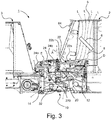
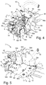
- Fig. 3-9 schematically illustrate different views and details of a steering device I for mutually steering a first vehicle unit 2 and a second vehicle unit 3 of an articulated vehicle 1, e.g. according to fig. 1 , according to an embodiment of the present invention.
- the steering device I comprises a steering member 10 for mutually steering the first vehicle unit 2 and the second vehicle unit 3, and a housing configuration 50 arranged to surroundingly protect the steering member10.
- the articulated vehicle 1 comprises an air intake 5 arranged in the upper portion of the front vehicle unit 2, and a radiator 6 arranged in the front vehicle unit 2 downstream of the air intake 5 to cool in the vehicle by means of said through the air intake 5 received air L, wherein air L heated through heat exchange is arranged to be streamed through the housing configuration 50.
- the air is arranged to stream in through the air intake 5 and further via the radiator 6 in an air stream path 8, wherein the heated air L is arranged to stream into the housing configuration 50 and out through openings of the housing configuration 50 constituting air outlets.
- the air intake 5 and the radiator 6 constitute a heating device.
- the steering member 10 of the steering device I comprises a front fastening member 12 arranged to be assembled at the first vehicle unit 2.
- the first vehicle unit 2 constitutes the front vehicle unit 2, wherein the front fastening member 12 is intended to be arranged on the rear end of the first front vehicle unit 2.
- the steering member 10 further comprises a rear fastening member 14 arranged to be assembled at the second vehicle unit 3, which consequently here constitutes the rear vehicle unit 3 such that the rear fastening member 14 is intended to be arranged at the front end of the rear vehicle unit 3.
- the steering member 10 comprises an essentially vertical link shaft A about which said vehicle units 2, 3 are pivotable.
- the front fastening member 12 is intended for fixed non-rotational assembling at the rear end of the front vehicle unit 2.
- the fastening member comprises a number of fasteners 12a, 12b, 12c, 12d.
- the front fastening member 12 has an essentially X-shaped configuration wherein openings are formed for said supply means.
- the steering member 10 further comprises a front steering link 16 which is pivotably connected to said front fastening member 12 about a first transversal horizontal shaft B.
- the rear fastening member 14 is intended for assembling at the front end of the rear vehicle unit 3.
- the rear fastening member 14 is arranged to allow rotation relative to the rear vehicle unit 3.
- the steering device 10 further comprises a rear steering link 18 which is rotatably connected to said rear fastening member 14 about a longitudinal shaft, i.e. rotatably journalled in bearings for allowing by means of the steering member 10 different side inclination positions of the front and rear vehicle units 2, 3.
- the rear steering link 18 is pivotably connected to said rear fastening member 14 about a second transversal horizontal shaft C.
- the front and rear steering link 16, 18 are articulately connected to each other over a steering link with the vertical link shaft A, the front and rear steering link 16, 18 forming a steering link unit 20.
- the steering member 10 further comprises a front tilt cylinder unit 22 and a rear tilt cylinder unit 24 as is evident from fig. 3 .
- the respective tilt cylinder unit 22, 24 comprises a cylinder part 22a, 24a and a piston rod part 22b, 24b.
- the respective tilt cylinder unit 22, 24 is according to an embodiment a hydraulic tilt cylinder unit 22, 24.
- the front fastening member 12 is articulately connected to the upper portion with an end area of said tilt cylinder unit 22 about a third transversal horizontal shaft D wherein an opposite end area of the front tilt cylinder unit 22 is articulately connected in the upper portion of the steering link unit 20.
- the rear fastening member 14 is articulately connected in the upper portion to an end area of said rear tilt cylinder unit 24 about a fourth transversal horizontal shaft E parallel to the third shaft D wherein an opposite end area of the rear tilt cylinder unit 24 is articulately connected in the upper portion of the steering link unit 20.
- the steering member 10 further comprises first and second steering elements in the shape of a first and second steering cylinder unit 30, 32 arranged to mutually swing said first and second vehicle unit 2, 3 about the link shaft A.
- the respective steering cylinder unit 30, 32 is in its one end area connected to the front steering link 16 at the respective vertical link shafts F, G.
- the respective steering cylinder unit is in its other end area connected to the rear steering link at the respective vertical link shaft H, J.
- the respective steering cylinder unit 30, 32 comprises a cylinder part 30a, 32a and a piston rod part 30b, 32b arranged to move in the cylinder part 30a, 32a.
- the steering cylinder units 30, 32 are arranged to co-operate in such a way that when one of the piston rod parts 30b, 32b is retracted in its cylinder part 30a, 32a, the other piston rod part 32b, 30b is projected out of its cylinder part 32a, 30a.
- the allied vehicle units 2, 3 are brought to be steered either to the left or to the right about the vertical link shaft A.
- said steering cylinder units 30, 32 are hydraulic.
- the four parallel transversal horizontal shafts B, C, D, E of the steering device I facilitates for the steering device I and thereby the allied vehicle units 2, 3 to perform vertical pivotal and link movements, wherein the horizontal shafts B, C, D, E may constitute link shafts in a parallelogram, such that the steering links 16, 18 and thereby the vehicle units 2, 3, also may perform mutual movements in the vertical direction.
- the steering device I further comprises said housing configuration 50 arranged to form a supply space S between the first and second vehicle units 2, 3.
- the housing configuration 50 is arranged in such a way that the steering cylinder units 30, 32 and also the tilt cylinder units 22, 24 essentially are surrounded such that they are protected from outer damage such as effective fire.
- the housing configuration 50 has ballistic protection properties.
- the steering device further comprises hoses 40 from the front vehicle unit 2 to the rear vehicle unit 3 for supply of the heating system in the rear vehicle unit 3.
- the housing configuration 50 comprises a front protection element arranged in connection to the front fastening member 12.
- the front protection element comprises a first protection element part 52a arranged to run along one side around to the underside and covering a part of the front side.
- the front protection element further comprises a second protection element part 52b opposite to the first protection element part 52a arranged to run along the other side around to the underside and covering a part of the front side.
- the front protection element comprises an intermediate protection element part 52c arranged on the underside between the first and second protection element part of the front protection element.
- the housing configuration 50 further comprises front side protection elements 54a, 54b, 55a, 55b arranged on each side in connection to the front steering link.
- Said front side protection elements comprise respective outer protection element parts 54a, 54b and inner protection element parts 55a, 55b at least partly overlapping each other.
- the inner protection part 55a is fixedly connected to the steering cylinder unit 30 and will consequently pivot with the steering cylinder unit 30.
- the inner protection element part 55b is connected to the steering cylinder unit 32 and will consequently pivot with the steering cylinder unit 32.
- the space between the outer and inner protection element parts forms opening for air outlet of the air streaming through the air intake via the radiator.
- the housing configuration 50 further comprises a rear protection element 56 arranged in connection to the rear fastening member 14.
- the rear protection element comprises a first protection element portion 56a arranged to run along one side and a second protection element portion 56b arranged to run along the opposite side, and an intermediate upper protection element portion 56c between the first and second protection element portions, said protection element portions 56a, 56b, 56c being constituted by one piece.
- the housing configuration 50 further comprises first and second rear side protection elements 58a, 58b arranged on each side in connection to the rear steering link.
- the rear side protection element 58a is pivotably journalled at the shaft H and the rear side protection element 58b is pivotably journalled at the shaftJ.
- the steering device comprises guide members 70a, 70b arranged in connection to the respective inner protection element part 55a, 55b and rear side protection element 58a 58b.
- the respective rear side protection element 58a, 58b is connected to the respective guide member, wherein the respective guide member is arranged to retain the respective rear side protection element 58a, 58b along the side by preventing them from swivelling out, and wherein the respective guide member 70a, 70 allows the respective rear protection element to move relative to the respective inner protection element part in the longitudinal direction of the steering member.
- the housing configuration further comprises a rear upper protection element 59 arranged on the upper side intermediate to the rear side protection elements 58a, 58b to protectively cover the rear steering link 18 and the rear tilt cylinder unit 24.
- the housing configuration further comprises third and fourth rear side protection elements 58c, 58d partly projecting from the side.
- the housing configuration 50 further comprises a front under protection element 60 arranged on the underside of the steering member pivotable about the vertical link shaft A in connection to the front steering link 16.
- the housing configuration 50 further comprises a rear under protection element 62 arranged on the underside of the steering member pivotable about the vertical link shaft A in connection to the rear steering link 18.
- the front under protection element 60 and the rear under protection element 62 are consequently pivotably arranged about the vertical link shaft A. the front and rear under protection element 60, 62 are consequently mutually movable relative to each other.
- the front and rear under protection element 60, 62 are arranged to, in a non-pivoting state of the vehicle partly sealingly overlap each other, and in a pivotable state of the vehicle providing a drainage opening O of the bottom part.
- Fig. 8 shows the front and rear under protection elements 60, 62 in a non-pivoting state
- fig. 9 shows the front and rear under protection elements 60, 62 in a pivoting state.
- the front vehicle unit has in the rear portion a hood like casing 64 which is arranged to protectively cover the front fastening member 12, the front steering link 16 and the front tilt cylinder unit 22.
- the housing configuration 50 has a telescopic function in that the housing configuration 50 comprises protection elements/protection element parts 55a, 55b, 58a, 58b arranged on each side thereof partly on each other and slidably relative to each other.
- said protection elements/protection element parts arranged slidably relative to each other are arranged such that when the vehicle units pivots relative to each other about the link shaft A the protection elements on one side slides together such that they cover more of each other and the protection elements on the opposite side slides apart such that they cover less of each other.
- a more fully covering protection even by pivoting of the vehicle units relative to each other is obtained.
- the housing configuration comprises a number of air outlets formed through openings between the above mentioned protection element and protection element parts for air outlet of the air L streaming through the air intake via the radiator such that the streaming air among others is let out through the side and downward.
- the steering member of the steering device I above comprises first and second steering elements arranged to mutually pivot said vehicle units, said steering elements being constituted by steering cylinder units with cylinder and piston, which steering cylinder units are hydraulic.
- the steering elements of the steering member described above are constituted by gear rack elements.
- the steering elements of the steering member described above are constituted by a linear motor, which according to a variant is built up with a ball screw and a ball nut which is arranged to run along the ball screw, wherein the nut is arranged to be moved by rotating the ball screw by means of an electric motor or hydraulic motor or the corresponding.
- the steering cylinder units of the steering vehicle described above are arranged such that they are protected by the housing configuration 50.
- said steering elements are arranged such that they are protected by one of the vehicle units, according to a variant internally to one of the vehicle units, according to another variant under one of the vehicle units.
- the steering member describe above comprises tilt elements, said tilt elements being constituted by tilt cylinder units with cylinder and piston rod, which tilt cylinder units are hydraulic.
- tilt elements of the steering member described above are constituted by gear rack elements.
- the tilt elements of the steering member described above of are constituted by a linear motor, which according to a variant is built up with a ball screw and a ball nut which is arranged to run along the ball screw, wherein the nut is arranged to be moved by rotating the ball screw by means of an electric motor or hydraulic motor or the corresponding.
- a steering device with a steering member for mutually steering a first vehicle unit and a second vehicle unit of an articulated vehicle, the steering member comprising an essentially vertical link shaft about which said vehicle units are pivotable, first and second steering elements in the shape of hydraulic steering cylinders arranged to mutually pivot said vehicle units, wherein the steering device comprises a housing configuration arranged to form a supply space between said vehicle units.
- Any suitable steering member with a housing configuration arranged to form a supply space between said vehicle units comprising means arranged for removal of stuff introduced in the supply space from the surrounding, said means comprising a heating device arranged to heat air intended to stream through the housing configuration such that snow/ice introduced into the housing configuration may be reduced/eliminated by means of the hot streaming air.
Landscapes
- Engineering & Computer Science (AREA)
- Mechanical Engineering (AREA)
- Chemical & Material Sciences (AREA)
- Combustion & Propulsion (AREA)
- Transportation (AREA)
- Steering Controls (AREA)
- Body Structure For Vehicles (AREA)
- Power Steering Mechanism (AREA)
- Cooling, Air Intake And Gas Exhaust, And Fuel Tank Arrangements In Propulsion Units (AREA)
- Steering-Linkage Mechanisms And Four-Wheel Steering (AREA)
Claims (13)
- Lenkvorrichtung (I), die ein Lenkelement (10) umfasst, mit dem eine erste Fahrzeugeinheit (2) und eine zweite Fahrzeugeinheit (3) eines Gelenkfahrzeugs (1) zueinander gelenkt werden, umfassend Einrichtungen (30, 32), mit der die Fahrzeugeinheiten zueinander geschwenkt werden, wobei die Lenkvorrichtung eine Gehäusekonstruktion (50) umfasst, die so eingerichtet ist, dass ein Zuführraum (S) zwischen den Fahrzeugeinheiten (2, 3) gebildet wird, wobei die Gehäusekonstruktion (50) so eingerichtet ist, dass sie einen Schutzraum bildet, in welchem zumindest ein Teil des Lenkelements (10) untergebracht ist, gekennzeichnet durch Einrichtungen (5, 6, 8, S; 60, 62, A, O) die zum Entfernen von Material, wie beispielsweise Schnee und/oder Eis und/oder Steinen und/oder Schotter oder dergleichen, in dem Zuführraum (S) eingerichtet sind, das aus der Umgebung eintritt, wobei die Einrichtung den Bodenteil der Gehäusekonstruktion (50) umfasst, der zwei zueinander bewegliche Schutzelemente (60, 62) umfasst, die so eingerichtet sind, dass sie in einem Nicht-Schwenkzustand des Fahrzeugs einander teilweise überlappen, und in einem Schwenkzustand des Fahrzeugs eine Ablauföffnung (O) des Bodenteils bilden.
- Lenkvorrichtung nach Anspruch 1, wobei das Lenkelement (10) eine im Wesentlichen vertikale Verbindungswelle (A) umfasst, um die die Fahrzeugeinheiten (2, 3) geschwenkt werden können.
- Lenkvorrichtung nach Anspruch 2, wobei die Schutzelemente (60, 62) um die vertikale Verbindungswelle (A) herum zueinander schwenkbar sind.
- Lenkvorrichtung nach einem der Ansprüche 1-3, wobei die Gehäusekonstruktion (50) eine separate Einheit bildet.
- Lenkvorrichtung nach einem der Ansprüche 1-4, wobei die Gehäusekonstruktion (50) eine Tunnelkonstruktion aufweist.
- Lenkvorrichtung nach einem der Ansprüche 1-5, wobei die Gehäusekonstruktion (50) ballistische Schutzeigenschaften aufweist.
- Lenkvorrichtung nach einem der Ansprüche 1-6, wobei die Einrichtung eine Heizvorrichtung (5, 6, 8) umfasst, die so eingerichtet ist, dass sie Luft (L) erhitzt, die durch die Gehäusekonstruktion (50) hindurch strömen soll.
- Lenkvorrichtung nach Anspruch 7, wobei die Einrichtung einen Lufteinlass (5), der in einer Fahrzeugeinheit angeordnet ist, sowie einen Radiator (6) umfasst, der stromab von dem Lufteinlass (5) angeordnet ist, wobei mittels Wärmeaustausch stromab von dem Radiator (6) erhitzte Luft (L) so eingerichtet ist, dass sie durch die Gehäusekonstruktion (50) hindurch strömt.
- Lenkvorrichtung nach Anspruch 8, wobei der Lufteinlass (5) und der Radiator (6) in Verbindung mit der ersten Fahrzeugeinheit (2) angeordnet sind, die die vordere Fahrzeugeinheit bildet.
- Lenkvorrichtung nach einem der Ansprüche 1-9, wobei die Gehäusekonstruktion (50) mehrere Luftauslässe umfasst.
- Lenkvorrichtung nach einem der Ansprüche 1-10, wobei die Einrichtung, mit der die Fahrzeugeinheiten (2, 3) zueinander geschwenkt werden, ein erstes und zweites Lenkelement (30, 32) umfasst.
- Gelenkfahrzeug (1), das eine Lenkvorrichtung (I) nach einem der Ansprüche 1-11 umfasst.
- Gelenkfahrzeug (1) nach Anspruch 12, wobei das Gelenkfahrzeug (1) ein Kettenfahrzeug ist.
Applications Claiming Priority (2)
| Application Number | Priority Date | Filing Date | Title |
|---|---|---|---|
| SE1150257A SE535738C2 (sv) | 2011-03-23 | 2011-03-23 | Styrdonsanordning för midjestyrt fordon |
| EP12760663.0A EP2688786B1 (de) | 2011-03-23 | 2012-03-19 | Lenkvorrichtung für ein gelenkfahrzeug |
Related Parent Applications (2)
| Application Number | Title | Priority Date | Filing Date |
|---|---|---|---|
| EP12760663.0A Division EP2688786B1 (de) | 2011-03-23 | 2012-03-19 | Lenkvorrichtung für ein gelenkfahrzeug |
| EP12760663.0A Division-Into EP2688786B1 (de) | 2011-03-23 | 2012-03-19 | Lenkvorrichtung für ein gelenkfahrzeug |
Publications (2)
| Publication Number | Publication Date |
|---|---|
| EP3018039A1 EP3018039A1 (de) | 2016-05-11 |
| EP3018039B1 true EP3018039B1 (de) | 2017-07-19 |
Family
ID=46879614
Family Applications (2)
| Application Number | Title | Priority Date | Filing Date |
|---|---|---|---|
| EP15191037.9A Active EP3018039B1 (de) | 2011-03-23 | 2012-03-19 | Lenkvorrichtung für ein gelenkfahrzeug |
| EP12760663.0A Active EP2688786B1 (de) | 2011-03-23 | 2012-03-19 | Lenkvorrichtung für ein gelenkfahrzeug |
Family Applications After (1)
| Application Number | Title | Priority Date | Filing Date |
|---|---|---|---|
| EP12760663.0A Active EP2688786B1 (de) | 2011-03-23 | 2012-03-19 | Lenkvorrichtung für ein gelenkfahrzeug |
Country Status (8)
| Country | Link |
|---|---|
| US (2) | US9108674B2 (de) |
| EP (2) | EP3018039B1 (de) |
| AU (2) | AU2012231831B2 (de) |
| BR (1) | BR112013023913B1 (de) |
| RU (1) | RU2594315C2 (de) |
| SE (1) | SE535738C2 (de) |
| SG (2) | SG10201602228UA (de) |
| WO (1) | WO2012128706A1 (de) |
Families Citing this family (6)
| Publication number | Priority date | Publication date | Assignee | Title |
|---|---|---|---|---|
| US9428869B2 (en) | 2014-10-24 | 2016-08-30 | Gomaco Corporation | Adjustable width trail paver |
| CA3295285A1 (en) | 2016-09-15 | 2026-03-02 | Terex Australia Pty Ltd | Crane counterweight and suspension |
| SE543611C2 (sv) * | 2018-10-24 | 2021-04-20 | Komatsu Forest Ab | Artikulerat fordon innefattande ett hydrostatiskt kraftöverföringsarrangemang med deplacementstyrning |
| SE543790C2 (en) * | 2019-12-18 | 2021-07-20 | Bae Systems Haegglunds Ab | Method and control device for controlling driving operation of an articulated tracked vehicle |
| SE543795C2 (en) * | 2019-12-18 | 2021-07-27 | Bae Systems Haegglunds Ab | Method and control device for controlling driving operation of an articulated tracked vehicle |
| SE547377C2 (en) * | 2022-08-16 | 2025-07-22 | Ponsse Oyj | Forest machine and joint of forest machine |
Family Cites Families (24)
| Publication number | Priority date | Publication date | Assignee | Title |
|---|---|---|---|---|
| US2116538A (en) * | 1934-03-26 | 1938-05-10 | Pullman Standard Car Mfg Co | Air conditioning system |
| US2933143A (en) * | 1957-06-25 | 1960-04-19 | Canadair Ltd | Articulated vehicle |
| US3035654A (en) * | 1958-02-21 | 1962-05-22 | Wilson Nuttall Raimond Enginee | Articulated tracked vehicles |
| US3491847A (en) * | 1967-06-15 | 1970-01-27 | Thomas P Abbott | Explosion cover |
| US3604526A (en) * | 1969-07-08 | 1971-09-14 | Omsteel Ind Inc | Articulated vehicle |
| US3865208A (en) * | 1973-05-21 | 1975-02-11 | Canadian Mine Services Ltd | Hydraulic drive apparatus for wheeled vehicle |
| CA1245510A (en) * | 1984-03-05 | 1988-11-29 | Arktos Developments Ltd. | All terrain vehicle and method of operating same |
| GB9200657D0 (en) * | 1992-01-14 | 1992-03-11 | Dosco Overseas Eng Ltd | Steering mechanism for articulated vehicles |
| US5725063A (en) * | 1995-08-14 | 1998-03-10 | Case Corporation | Articulated work vehicle |
| CA2157265C (en) * | 1995-08-30 | 1999-02-02 | Donald Gauvin | Articulated vehicle |
| US5873431A (en) * | 1996-05-03 | 1999-02-23 | Joy Mm Delaware, Inc. | Articulated vehicle |
| US6892839B2 (en) * | 1998-10-14 | 2005-05-17 | James W. Cooper | Multi-combination vehicle incorporating a power trailer |
| SE513266C2 (sv) * | 1998-12-16 | 2000-08-14 | Haegglunds Vehicle Ab | Styrdon för midjestyrt bandfordon |
| US6021843A (en) * | 1999-03-15 | 2000-02-08 | Roach; Vincent | Snow melting apparatus for wheel wells |
| RU2206859C1 (ru) | 2002-03-06 | 2003-06-20 | Общевойсковая Академия Вооруженных Сил Российской Федерации | Устройство сочленения двузвенной гусеничной машины |
| CA2443863C (en) * | 2002-05-24 | 2007-02-27 | Cooper, James W. | System for the control of multiple engines in a multi-combination vehicle |
| FR2846931B1 (fr) * | 2002-11-07 | 2006-06-16 | Bernard Coeuret | Vehicule leger de chantier, notamment vehicule a benne |
| US20050039973A1 (en) * | 2003-08-21 | 2005-02-24 | Bruce Clark | Yaw, pitch and roll apparatus for a multiple unit vehicle |
| US8430188B2 (en) * | 2006-12-11 | 2013-04-30 | Vermeer Manufacturing Company | Apparatus for converting a wheeled vehicle to a tracked vehicle |
| JP2010132238A (ja) * | 2008-12-08 | 2010-06-17 | Jtekt Corp | 車両用操舵装置 |
| SE534622C2 (sv) * | 2009-07-07 | 2011-10-25 | Bae Systems Haegglunds Ab | Midjestyrt bandfordon |
| SE534881C2 (sv) * | 2009-09-24 | 2012-01-31 | Bae Systems Haegglunds Ab | Skyddsanordning för midjestyrt fordon och ett förfarande för att styra ett förstyvningsmedel för en sådan skyddsanordning |
| SE535049C2 (sv) * | 2009-09-25 | 2012-03-27 | Bae Systems Haegglunds Ab | Styrdon för midjestyrt fordon |
| US8573505B1 (en) * | 2010-04-01 | 2013-11-05 | Dana A. Hennessy | Thawing system for machinery undercarriages |
-
2011
- 2011-03-23 SE SE1150257A patent/SE535738C2/sv unknown
-
2012
- 2012-03-19 SG SG10201602228UA patent/SG10201602228UA/en unknown
- 2012-03-19 EP EP15191037.9A patent/EP3018039B1/de active Active
- 2012-03-19 AU AU2012231831A patent/AU2012231831B2/en active Active
- 2012-03-19 US US14/006,953 patent/US9108674B2/en active Active
- 2012-03-19 BR BR112013023913-1A patent/BR112013023913B1/pt active IP Right Grant
- 2012-03-19 WO PCT/SE2012/050301 patent/WO2012128706A1/en not_active Ceased
- 2012-03-19 EP EP12760663.0A patent/EP2688786B1/de active Active
- 2012-03-19 RU RU2013147146/11A patent/RU2594315C2/ru active
- 2012-03-19 SG SG2013064472A patent/SG192953A1/en unknown
-
2015
- 2015-07-13 US US14/798,120 patent/US9409599B2/en active Active
-
2016
- 2016-10-31 AU AU2016253542A patent/AU2016253542B2/en active Active
Non-Patent Citations (1)
| Title |
|---|
| None * |
Also Published As
| Publication number | Publication date |
|---|---|
| US9108674B2 (en) | 2015-08-18 |
| RU2594315C2 (ru) | 2016-08-10 |
| EP2688786B1 (de) | 2015-12-16 |
| AU2016253542B2 (en) | 2018-04-05 |
| SG192953A1 (en) | 2013-10-30 |
| AU2012231831B2 (en) | 2016-09-15 |
| BR112013023913A2 (pt) | 2016-12-13 |
| US20140190756A1 (en) | 2014-07-10 |
| US20150314806A1 (en) | 2015-11-05 |
| EP3018039A1 (de) | 2016-05-11 |
| AU2016253542A1 (en) | 2016-11-17 |
| WO2012128706A1 (en) | 2012-09-27 |
| EP2688786A4 (de) | 2014-11-19 |
| EP2688786A1 (de) | 2014-01-29 |
| SG10201602228UA (en) | 2016-04-28 |
| US9409599B2 (en) | 2016-08-09 |
| BR112013023913B1 (pt) | 2021-07-20 |
| SE1150257A1 (sv) | 2012-09-24 |
| AU2012231831A1 (en) | 2013-10-24 |
| RU2013147146A (ru) | 2015-04-27 |
| SE535738C2 (sv) | 2012-11-27 |
Similar Documents
| Publication | Publication Date | Title |
|---|---|---|
| AU2016253542B2 (en) | Steering device for articulated vehicle | |
| US9193385B2 (en) | Steering device for articulated vehicle | |
| CA2887198C (en) | Heavy goods vehicle with normal steering and crab steering | |
| US10077974B2 (en) | Highly mobile vehicle suspension system with blast mitigation features | |
| KR102256018B1 (ko) | 회전 피벗 아암 위치설정 조립체 | |
| EP2480441B1 (de) | Schutzvorrichtung für ein gelenkfahrzeug | |
| US20180043926A1 (en) | Electric Power Steering Unit With Offset Link Mechanism | |
| EP2025580B1 (de) | Lenkgruppe der Räder einer Achse eines Fahrzeugs | |
| US20120073896A1 (en) | Vehicle having articulated steering, in particular armored vehicle | |
| EP3371431B1 (de) | Traktor mit kühlsystem | |
| CN104703859B (zh) | 转向盘轴的保护罩 | |
| SE536158C2 (sv) | Styrdonsanordning för midjestyrt fordon | |
| AU2008331804B2 (en) | Sliding panel arrangement for a vehicle | |
| JP7493791B2 (ja) | 無人車両 | |
| RU2270126C1 (ru) | Транспортное средство | |
| RU2826274C1 (ru) | Кабина с устройством для защиты от сбрасываемых сверху взрывоопасных предметов | |
| RU2390458C1 (ru) | Плавательное оборудование колесного транспортного средства | |
| IL271588B2 (en) | The deflector and vehicles with such a deflector | |
| IT202300016851A1 (it) | Macchina per sminare |
Legal Events
| Date | Code | Title | Description |
|---|---|---|---|
| PUAI | Public reference made under article 153(3) epc to a published international application that has entered the european phase |
Free format text: ORIGINAL CODE: 0009012 |
|
| AC | Divisional application: reference to earlier application |
Ref document number: 2688786 Country of ref document: EP Kind code of ref document: P |
|
| AK | Designated contracting states |
Kind code of ref document: A1 Designated state(s): AL AT BE BG CH CY CZ DE DK EE ES FI FR GB GR HR HU IE IS IT LI LT LU LV MC MK MT NL NO PL PT RO RS SE SI SK SM TR |
|
| 17P | Request for examination filed |
Effective date: 20161021 |
|
| RBV | Designated contracting states (corrected) |
Designated state(s): AL AT BE BG CH CY CZ DE DK EE ES FI FR GB GR HR HU IE IS IT LI LT LU LV MC MK MT NL NO PL PT RO RS SE SI SK SM TR |
|
| GRAP | Despatch of communication of intention to grant a patent |
Free format text: ORIGINAL CODE: EPIDOSNIGR1 |
|
| STAA | Information on the status of an ep patent application or granted ep patent |
Free format text: STATUS: GRANT OF PATENT IS INTENDED |
|
| INTG | Intention to grant announced |
Effective date: 20170320 |
|
| GRAS | Grant fee paid |
Free format text: ORIGINAL CODE: EPIDOSNIGR3 |
|
| GRAA | (expected) grant |
Free format text: ORIGINAL CODE: 0009210 |
|
| STAA | Information on the status of an ep patent application or granted ep patent |
Free format text: STATUS: THE PATENT HAS BEEN GRANTED |
|
| AC | Divisional application: reference to earlier application |
Ref document number: 2688786 Country of ref document: EP Kind code of ref document: P |
|
| AK | Designated contracting states |
Kind code of ref document: B1 Designated state(s): AL AT BE BG CH CY CZ DE DK EE ES FI FR GB GR HR HU IE IS IT LI LT LU LV MC MK MT NL NO PL PT RO RS SE SI SK SM TR |
|
| REG | Reference to a national code |
Ref country code: GB Ref legal event code: FG4D |
|
| REG | Reference to a national code |
Ref country code: CH Ref legal event code: EP |
|
| REG | Reference to a national code |
Ref country code: IE Ref legal event code: FG4D |
|
| REG | Reference to a national code |
Ref country code: AT Ref legal event code: REF Ref document number: 910098 Country of ref document: AT Kind code of ref document: T Effective date: 20170815 |
|
| REG | Reference to a national code |
Ref country code: DE Ref legal event code: R096 Ref document number: 602012034913 Country of ref document: DE |
|
| REG | Reference to a national code |
Ref country code: NL Ref legal event code: FP |
|
| REG | Reference to a national code |
Ref country code: LT Ref legal event code: MG4D |
|
| REG | Reference to a national code |
Ref country code: AT Ref legal event code: MK05 Ref document number: 910098 Country of ref document: AT Kind code of ref document: T Effective date: 20170719 |
|
| PG25 | Lapsed in a contracting state [announced via postgrant information from national office to epo] |
Ref country code: HR Free format text: LAPSE BECAUSE OF FAILURE TO SUBMIT A TRANSLATION OF THE DESCRIPTION OR TO PAY THE FEE WITHIN THE PRESCRIBED TIME-LIMIT Effective date: 20170719 Ref country code: SE Free format text: LAPSE BECAUSE OF FAILURE TO SUBMIT A TRANSLATION OF THE DESCRIPTION OR TO PAY THE FEE WITHIN THE PRESCRIBED TIME-LIMIT Effective date: 20170719 Ref country code: AT Free format text: LAPSE BECAUSE OF FAILURE TO SUBMIT A TRANSLATION OF THE DESCRIPTION OR TO PAY THE FEE WITHIN THE PRESCRIBED TIME-LIMIT Effective date: 20170719 Ref country code: NO Free format text: LAPSE BECAUSE OF FAILURE TO SUBMIT A TRANSLATION OF THE DESCRIPTION OR TO PAY THE FEE WITHIN THE PRESCRIBED TIME-LIMIT Effective date: 20171019 Ref country code: LT Free format text: LAPSE BECAUSE OF FAILURE TO SUBMIT A TRANSLATION OF THE DESCRIPTION OR TO PAY THE FEE WITHIN THE PRESCRIBED TIME-LIMIT Effective date: 20170719 Ref country code: FI Free format text: LAPSE BECAUSE OF FAILURE TO SUBMIT A TRANSLATION OF THE DESCRIPTION OR TO PAY THE FEE WITHIN THE PRESCRIBED TIME-LIMIT Effective date: 20170719 |
|
| PG25 | Lapsed in a contracting state [announced via postgrant information from national office to epo] |
Ref country code: PL Free format text: LAPSE BECAUSE OF FAILURE TO SUBMIT A TRANSLATION OF THE DESCRIPTION OR TO PAY THE FEE WITHIN THE PRESCRIBED TIME-LIMIT Effective date: 20170719 Ref country code: LV Free format text: LAPSE BECAUSE OF FAILURE TO SUBMIT A TRANSLATION OF THE DESCRIPTION OR TO PAY THE FEE WITHIN THE PRESCRIBED TIME-LIMIT Effective date: 20170719 Ref country code: BG Free format text: LAPSE BECAUSE OF FAILURE TO SUBMIT A TRANSLATION OF THE DESCRIPTION OR TO PAY THE FEE WITHIN THE PRESCRIBED TIME-LIMIT Effective date: 20171019 Ref country code: RS Free format text: LAPSE BECAUSE OF FAILURE TO SUBMIT A TRANSLATION OF THE DESCRIPTION OR TO PAY THE FEE WITHIN THE PRESCRIBED TIME-LIMIT Effective date: 20170719 Ref country code: IS Free format text: LAPSE BECAUSE OF FAILURE TO SUBMIT A TRANSLATION OF THE DESCRIPTION OR TO PAY THE FEE WITHIN THE PRESCRIBED TIME-LIMIT Effective date: 20171119 Ref country code: GR Free format text: LAPSE BECAUSE OF FAILURE TO SUBMIT A TRANSLATION OF THE DESCRIPTION OR TO PAY THE FEE WITHIN THE PRESCRIBED TIME-LIMIT Effective date: 20171020 Ref country code: ES Free format text: LAPSE BECAUSE OF FAILURE TO SUBMIT A TRANSLATION OF THE DESCRIPTION OR TO PAY THE FEE WITHIN THE PRESCRIBED TIME-LIMIT Effective date: 20170719 |
|
| REG | Reference to a national code |
Ref country code: FR Ref legal event code: PLFP Year of fee payment: 7 |
|
| REG | Reference to a national code |
Ref country code: DE Ref legal event code: R097 Ref document number: 602012034913 Country of ref document: DE |
|
| PG25 | Lapsed in a contracting state [announced via postgrant information from national office to epo] |
Ref country code: RO Free format text: LAPSE BECAUSE OF FAILURE TO SUBMIT A TRANSLATION OF THE DESCRIPTION OR TO PAY THE FEE WITHIN THE PRESCRIBED TIME-LIMIT Effective date: 20170719 Ref country code: DK Free format text: LAPSE BECAUSE OF FAILURE TO SUBMIT A TRANSLATION OF THE DESCRIPTION OR TO PAY THE FEE WITHIN THE PRESCRIBED TIME-LIMIT Effective date: 20170719 Ref country code: CZ Free format text: LAPSE BECAUSE OF FAILURE TO SUBMIT A TRANSLATION OF THE DESCRIPTION OR TO PAY THE FEE WITHIN THE PRESCRIBED TIME-LIMIT Effective date: 20170719 |
|
| PLBE | No opposition filed within time limit |
Free format text: ORIGINAL CODE: 0009261 |
|
| STAA | Information on the status of an ep patent application or granted ep patent |
Free format text: STATUS: NO OPPOSITION FILED WITHIN TIME LIMIT |
|
| PG25 | Lapsed in a contracting state [announced via postgrant information from national office to epo] |
Ref country code: SM Free format text: LAPSE BECAUSE OF FAILURE TO SUBMIT A TRANSLATION OF THE DESCRIPTION OR TO PAY THE FEE WITHIN THE PRESCRIBED TIME-LIMIT Effective date: 20170719 Ref country code: SK Free format text: LAPSE BECAUSE OF FAILURE TO SUBMIT A TRANSLATION OF THE DESCRIPTION OR TO PAY THE FEE WITHIN THE PRESCRIBED TIME-LIMIT Effective date: 20170719 Ref country code: EE Free format text: LAPSE BECAUSE OF FAILURE TO SUBMIT A TRANSLATION OF THE DESCRIPTION OR TO PAY THE FEE WITHIN THE PRESCRIBED TIME-LIMIT Effective date: 20170719 |
|
| 26N | No opposition filed |
Effective date: 20180420 |
|
| PG25 | Lapsed in a contracting state [announced via postgrant information from national office to epo] |
Ref country code: SI Free format text: LAPSE BECAUSE OF FAILURE TO SUBMIT A TRANSLATION OF THE DESCRIPTION OR TO PAY THE FEE WITHIN THE PRESCRIBED TIME-LIMIT Effective date: 20170719 |
|
| REG | Reference to a national code |
Ref country code: CH Ref legal event code: PL |
|
| PG25 | Lapsed in a contracting state [announced via postgrant information from national office to epo] |
Ref country code: MC Free format text: LAPSE BECAUSE OF FAILURE TO SUBMIT A TRANSLATION OF THE DESCRIPTION OR TO PAY THE FEE WITHIN THE PRESCRIBED TIME-LIMIT Effective date: 20170719 |
|
| REG | Reference to a national code |
Ref country code: BE Ref legal event code: MM Effective date: 20180331 |
|
| REG | Reference to a national code |
Ref country code: IE Ref legal event code: MM4A |
|
| PG25 | Lapsed in a contracting state [announced via postgrant information from national office to epo] |
Ref country code: LU Free format text: LAPSE BECAUSE OF NON-PAYMENT OF DUE FEES Effective date: 20180319 |
|
| PG25 | Lapsed in a contracting state [announced via postgrant information from national office to epo] |
Ref country code: IE Free format text: LAPSE BECAUSE OF NON-PAYMENT OF DUE FEES Effective date: 20180319 |
|
| PG25 | Lapsed in a contracting state [announced via postgrant information from national office to epo] |
Ref country code: BE Free format text: LAPSE BECAUSE OF NON-PAYMENT OF DUE FEES Effective date: 20180331 Ref country code: LI Free format text: LAPSE BECAUSE OF NON-PAYMENT OF DUE FEES Effective date: 20180331 Ref country code: CH Free format text: LAPSE BECAUSE OF NON-PAYMENT OF DUE FEES Effective date: 20180331 |
|
| PG25 | Lapsed in a contracting state [announced via postgrant information from national office to epo] |
Ref country code: MT Free format text: LAPSE BECAUSE OF NON-PAYMENT OF DUE FEES Effective date: 20180319 |
|
| PG25 | Lapsed in a contracting state [announced via postgrant information from national office to epo] |
Ref country code: TR Free format text: LAPSE BECAUSE OF FAILURE TO SUBMIT A TRANSLATION OF THE DESCRIPTION OR TO PAY THE FEE WITHIN THE PRESCRIBED TIME-LIMIT Effective date: 20170719 |
|
| PG25 | Lapsed in a contracting state [announced via postgrant information from national office to epo] |
Ref country code: PT Free format text: LAPSE BECAUSE OF FAILURE TO SUBMIT A TRANSLATION OF THE DESCRIPTION OR TO PAY THE FEE WITHIN THE PRESCRIBED TIME-LIMIT Effective date: 20170719 |
|
| PG25 | Lapsed in a contracting state [announced via postgrant information from national office to epo] |
Ref country code: HU Free format text: LAPSE BECAUSE OF FAILURE TO SUBMIT A TRANSLATION OF THE DESCRIPTION OR TO PAY THE FEE WITHIN THE PRESCRIBED TIME-LIMIT; INVALID AB INITIO Effective date: 20120319 Ref country code: MK Free format text: LAPSE BECAUSE OF NON-PAYMENT OF DUE FEES Effective date: 20170719 Ref country code: CY Free format text: LAPSE BECAUSE OF FAILURE TO SUBMIT A TRANSLATION OF THE DESCRIPTION OR TO PAY THE FEE WITHIN THE PRESCRIBED TIME-LIMIT Effective date: 20170719 |
|
| PG25 | Lapsed in a contracting state [announced via postgrant information from national office to epo] |
Ref country code: AL Free format text: LAPSE BECAUSE OF FAILURE TO SUBMIT A TRANSLATION OF THE DESCRIPTION OR TO PAY THE FEE WITHIN THE PRESCRIBED TIME-LIMIT Effective date: 20170719 |
|
| P01 | Opt-out of the competence of the unified patent court (upc) registered |
Effective date: 20230525 |
|
| PGFP | Annual fee paid to national office [announced via postgrant information from national office to epo] |
Ref country code: NL Payment date: 20260123 Year of fee payment: 15 |
|
| PGFP | Annual fee paid to national office [announced via postgrant information from national office to epo] |
Ref country code: GB Payment date: 20260119 Year of fee payment: 15 |
|
| PGFP | Annual fee paid to national office [announced via postgrant information from national office to epo] |
Ref country code: DE Payment date: 20260216 Year of fee payment: 15 |
|
| PGFP | Annual fee paid to national office [announced via postgrant information from national office to epo] |
Ref country code: IT Payment date: 20260218 Year of fee payment: 15 |
|
| PGFP | Annual fee paid to national office [announced via postgrant information from national office to epo] |
Ref country code: FR Payment date: 20260120 Year of fee payment: 15 |