EP3018014A1 - Air bag with uninflated pocket - Google Patents
Air bag with uninflated pocket Download PDFInfo
- Publication number
- EP3018014A1 EP3018014A1 EP15003167.2A EP15003167A EP3018014A1 EP 3018014 A1 EP3018014 A1 EP 3018014A1 EP 15003167 A EP15003167 A EP 15003167A EP 3018014 A1 EP3018014 A1 EP 3018014A1
- Authority
- EP
- European Patent Office
- Prior art keywords
- protection device
- peripheral edge
- front portion
- panel
- Prior art date
- Legal status (The legal status is an assumption and is not a legal conclusion. Google has not performed a legal analysis and makes no representation as to the accuracy of the status listed.)
- Granted
Links
Images


Classifications
-
- B—PERFORMING OPERATIONS; TRANSPORTING
- B60—VEHICLES IN GENERAL
- B60R—VEHICLES, VEHICLE FITTINGS, OR VEHICLE PARTS, NOT OTHERWISE PROVIDED FOR
- B60R21/00—Arrangements or fittings on vehicles for protecting or preventing injuries to occupants or pedestrians in case of accidents or other traffic risks
- B60R21/02—Occupant safety arrangements or fittings, e.g. crash pads
- B60R21/16—Inflatable occupant restraints or confinements designed to inflate upon impact or impending impact, e.g. air bags
- B60R21/23—Inflatable members
- B60R21/231—Inflatable members characterised by their shape, construction or spatial configuration
-
- B—PERFORMING OPERATIONS; TRANSPORTING
- B60—VEHICLES IN GENERAL
- B60R—VEHICLES, VEHICLE FITTINGS, OR VEHICLE PARTS, NOT OTHERWISE PROVIDED FOR
- B60R21/00—Arrangements or fittings on vehicles for protecting or preventing injuries to occupants or pedestrians in case of accidents or other traffic risks
- B60R21/02—Occupant safety arrangements or fittings, e.g. crash pads
- B60R21/16—Inflatable occupant restraints or confinements designed to inflate upon impact or impending impact, e.g. air bags
- B60R21/23—Inflatable members
- B60R21/231—Inflatable members characterised by their shape, construction or spatial configuration
- B60R21/2334—Expansion control features
- B60R21/2338—Tethers
-
- B—PERFORMING OPERATIONS; TRANSPORTING
- B60—VEHICLES IN GENERAL
- B60R—VEHICLES, VEHICLE FITTINGS, OR VEHICLE PARTS, NOT OTHERWISE PROVIDED FOR
- B60R21/00—Arrangements or fittings on vehicles for protecting or preventing injuries to occupants or pedestrians in case of accidents or other traffic risks
- B60R21/02—Occupant safety arrangements or fittings, e.g. crash pads
- B60R21/16—Inflatable occupant restraints or confinements designed to inflate upon impact or impending impact, e.g. air bags
- B60R21/23—Inflatable members
- B60R21/235—Inflatable members characterised by their material
-
- B—PERFORMING OPERATIONS; TRANSPORTING
- B60—VEHICLES IN GENERAL
- B60R—VEHICLES, VEHICLE FITTINGS, OR VEHICLE PARTS, NOT OTHERWISE PROVIDED FOR
- B60R21/00—Arrangements or fittings on vehicles for protecting or preventing injuries to occupants or pedestrians in case of accidents or other traffic risks
- B60R21/02—Occupant safety arrangements or fittings, e.g. crash pads
- B60R21/16—Inflatable occupant restraints or confinements designed to inflate upon impact or impending impact, e.g. air bags
- B60R21/23—Inflatable members
- B60R21/231—Inflatable members characterised by their shape, construction or spatial configuration
- B60R21/2334—Expansion control features
- B60R21/2338—Tethers
- B60R2021/23382—Internal tether means
Definitions
- Passenger air bags are typically stored in a deflated condition in a housing that is mounted to the vehicle instrument panel.
- An air bag door is connectable with the housing and/or instrument panel to help enclose and conceal the air bag in a stored condition.
- the air bag door opens to permit the air bag to move to an inflated position.
- the air bag door opens as a result of forces exerted on the door by the inflating air bag.
- the invention provides an inflatable vehicle occupant protection device for being inflated with inflation fluid towards a seat of the vehicle, the protection device comprising: a front portion presented towards the vehicle seat and helping to define an inflatable volume, the front portion including a pair of extensions that are overlaid on one another and interconnected to form a pocket defining a collapsed volume outside the inflatable volume, the pocket extending horizontally across the front portion and towards the inflatable volume; and a tether having a first end portion secured to both interconnected extensions and a second end portion secured to a portion of the protection device such that the size of the pocket remains larger than a predetermined amount when the protection device is fully inflated.
- an inflatable vehicle occupant protection device for being inflated with inflation fluid towards a seat of the vehicle
- the protection device comprising: a front portion presented towards the vehicle seat and including a pair of extensions that are overlaid on one another and interconnected to form a pocket; a rear portion opposite the front portion; first and second lateral portions interconnecting the front portion and the rear portion to define an inflatable volume, wherein the pocket defines a collapsed volume outside the inflatable volume, the pocket extending horizontally across the front portion and towards the inflatable volume; and a tether having a first end portion secured to both interconnected extensions and a second end portion secured to the rear portion of the protection device such that the size of the pocket remains larger than a predetermined amount when the protection device is fully inflated.
- the inward pocket 100 has a depth extending in a fore-aft direction of the vehicle 12 from the front portion 70 of the air bag 14 towards the rear portion 76 and may terminate prior to the rear portion. As best shown in Fig. 3 , the inward pocket 100 divides the front portion 70 of the air bag 14 into a pair of laterally extending inflatable lobes 110 positioned on opposite sides of the pocket. Alternatively, the inward pocket 100 may extend through the entire air bag 14 from the front portion 70 to the rear portion 76 (not shown).
- the third peripheral edge 130 includes a first notch 146 positioned adjacent the first peripheral edge 126, a second notch 148 positioned adjacent the second peripheral edge 128, and third through sixth notches 150, 152, 154, 156, 158 positioned between the first and second notches.
- the first, second, and third peripheral edges 226, 228, 230 each include a series of notches for helping to assemble the air bag 14.
- the first peripheral edge 226 includes a first notch 234 positioned adjacent the opening 232, a second notch 236 positioned adjacent the third peripheral edge 230, and a third notch 238 positioned between the first and second notches.
- the second peripheral edge 228 includes a first notch 240 positioned adjacent the opening 232, a second notch 242 positioned adjacent the third peripheral edge 230, and a third notch 244 positioned between the first and second notches.
- the third peripheral edge 230 includes a first notch 246 positioned adjacent the first peripheral edge 226, a second notch 248 positioned adjacent the second peripheral edge 228, and third through seventh notches 250, 252, 254, 256, 258 positioned between the first and second notches.
- the third peripheral edge 330 extends from the second peripheral edge 328 and away from the first peripheral edge 326 to form one or more extensions 344 of material. As shown in Fig. 7 , a single extension 344 extends from the second peripheral edge 328.
- the extension 344 has an arcuate or semicircular contour, although the extension may have alternative shapes, such as square, triangular, rectangular or the like.
- An indicator or marker 342 is provided on the third peripheral edge 330 at the furthest point from the first peripheral edge 326.
- the first peripheral edge 326 includes a series of notches for helping to assemble the air bag 14.
- the first peripheral edge 326 includes a first notch 350 positioned adjacent the second peripheral edge 328 on one side of the extension 344, a second notch 352 positioned adjacent the second peripheral edge on the other side of the extension, and third through sixth notches 354, 356, 358, 360 positioned between the first and second notches.
- the seam (not shown) then secures the portion of the third peripheral edge 230 of the second panel 220 starting from the fifth notch 254 and ending at the first peripheral edge 226 to the portion of the first peripheral edge 326 of the third panel 320 starting from the second peripheral edge 328, traveling counterclockwise along the first peripheral edge 326 (as viewed in Fig. 7 ), and ending at the midpoint of the first peripheral edge 326.
- the first peripheral edge 426 of the fourth panel 420 is secured by a seam to the third peripheral edge 130 of the first panel 120.
- the second notch 148, seventh notch 158, sixth notch 156, and fifth notch 154 on the third peripheral edge 130 of the first panel 120 are aligned with the fifth notch 458, fourth notch 456, third notch 454, and first notch 450, respectively, on the first peripheral edge 426 of the fourth panel 420.
- the first peripheral edge 426 of the fourth panel 420 is also secured by a seam to the third peripheral edge 230 of the second panel 220.
- the second notch 248, seventh notch 258, sixth notch 256, and fifth notch 254 on the third peripheral edge 230 of the second panel 220 are aligned with the fifth notch 458, sixth notch 460, seventh notch 462, and second notch 452, respectively, on the first peripheral edge 426 of the fourth panel 420.
- the seam (not shown) then secures the portion of the third peripheral edge 230 of the second panel 220 starting from the fifth notch 254 and ending at the second peripheral edge 228 to the portion of the first peripheral edge 426 of the fourth panel 420 starting from the second peripheral edge 428, traveling counterclockwise along the first peripheral edge 426 (as viewed in Fig. 7 ), and ending at the fifth notch 458.
- the first, second, third, and fourth panels 120, 220, 320, 420 are secured to one another such that the pocket 100 and the tether 500 extend inward toward the inflatable volume 54 of the air bag 14 prior to inflation of the air bag.
- the pocket 100 extends away from the front panel 72 of the air bag towards the rear portion 76 to define the collapsed volume 102.
- the pocket 100 extends inward relative to the front panel 72 towards the rear portion 76 of the air bag 14 when the air bag 14 is fully inflated.
- the occupant's head 21 is positioned at or below the pocket 100.
- the shorter occupant 20 therefore engages and interacts with only the lower lobe 110 of the air bag 14, which deflects relative to the substantially stationary upper lobe 110.
- the tether 500 is taught the pocket 100 allows the shorter occupant 20 to engage and interact with the lower lobe 110 without affecting the upper lobe 110.
- the extension 444 is compressed or shortened under the impact of the penetrating shorter occupant 20.
Landscapes
- Engineering & Computer Science (AREA)
- Mechanical Engineering (AREA)
- Air Bags (AREA)
Abstract
Description
- The present invention relates to an apparatus for helping to protect an occupant of a vehicle. More particularly, the present invention relates to an air bag inflatable between an instrument panel and a front seat occupant of a vehicle.
- It is known to provide an inflatable vehicle occupant protection device, such as an air bag, for helping to protect an occupant of a vehicle. One particular type of air bag is a frontal air bag inflatable between an occupant of a front seat of the vehicle and an instrument panel of the vehicle. Such air bags may be driver air bags or passenger air bags. When inflated, the driver and passenger air bags help protect the occupant from impacts with parts of the vehicle such as the instrument panel and/or a steering wheel of the vehicle.
- Passenger air bags are typically stored in a deflated condition in a housing that is mounted to the vehicle instrument panel. An air bag door is connectable with the housing and/or instrument panel to help enclose and conceal the air bag in a stored condition. Upon deployment of the passenger air bag, the air bag door opens to permit the air bag to move to an inflated position. The air bag door opens as a result of forces exerted on the door by the inflating air bag.
- The position of the occupant in the vehicle seat may dictate how the air bag is configured in order to more adequately protect the occupant during vehicle crashes. For instance, it may be desirable to protect the occupant from striking or being struck by the deploying air bag with high restraint forces. Such is the case when the occupant is unbelted and, thus, is positioned closer to the instrument panel during air bag deployment than a belted occupant. Rearward facing car seats that carry infants are also positioned on the vehicle seat in a position where an air bag is likely to deploy.
- According to the invention, such objective(s) are solved by an inflatable vehicle occupant protection device is provided for being inflated with inflation fluid towards a seat of the vehicle. The protection device includes a front portion presented towards the vehicle seat and helping to define an inflatable volume. The front portion includes a pair of extensions overlaid on one another and interconnected to form a pocket defining a collapsed volume outside the inflatable volume. The pocket extends horizontally across the front portion and towards the inflatable volume. A tether has a first end portion secured to both interconnected extensions and a second end portion secured to a portion of the protection device such that the size of the pocket remains larger than a predetermined amount when the protection device is fully inflated.
- In accordance with another embodiment of the present invention, an inflatable vehicle occupant protection device for being inflated with inflation fluid towards a seat of the vehicle is provided which includes a front portion presented towards the vehicle seat and having a pair of extensions overlaid on one another and interconnected to form a pocket. A rear portion is provided opposite the front portion and first and second lateral portions interconnect the front portion and the rear portion to define an inflatable volume. The pocket defines a collapsed volume outside the inflatable volume. The pocket extends horizontally across the front portion and towards the inflatable volume. A tether has a first end portion secured to both interconnected extensions and a second end portion secured to the rear portion of the protection device such that the size of the pocket remains larger than a predetermined amount when the protection device is fully inflated.
- According to a preferred embodiment, the invention provides an inflatable vehicle occupant protection device for being inflated with inflation fluid towards a seat of the vehicle, the protection device comprising: a front portion presented towards the vehicle seat and helping to define an inflatable volume, the front portion including a pair of extensions that are overlaid on one another and interconnected to form a pocket defining a collapsed volume outside the inflatable volume, the pocket extending horizontally across the front portion and towards the inflatable volume; and a tether having a first end portion secured to both interconnected extensions and a second end portion secured to a portion of the protection device such that the size of the pocket remains larger than a predetermined amount when the protection device is fully inflated.
- Preferably, the pocket divides the front portion into an upper lobe and a lower lobe.
- Further preferably, the lower lobe provides a first resistance to occupant penetration and the upper lobe provides a second, lower resistance to occupant penetration.
- According to a preferred embodiment, the lower lobe provides a first resistance to occupant penetration and the lower lobe and the upper lobe cooperate to provide a second, higher resistance to occupant penetration.
- According to another preferred embodiment, the lower lobe is movable relative to the upper lobe.
- According to a preferred embodiment, the pocket is positioned closer to a top portion than a bottom portion of the protection device.
- According to another preferred embodiment, the pocket extends horizontally across only a part of the front portion.
- According to yet another preferred embodiment, the front portion is formed by first and second panels that each includes one of the extensions of material forming the pocket.
- Preferably, the interconnected extensions are identical and have an inward condition forming the pocket.
- According to a further preferred embodiment, the first panel includes a first peripheral edge and a second peripheral edge extending from the first peripheral edge to define the extension of the first panel, the second panel including a first peripheral edge and a second peripheral edge extending from the first peripheral edge to define the extension of the second panel, the first peripheral edges being interconnected along a seam and the second peripheral edges being interconnected along a seam to form the pocket.
- More preferably, the first peripheral edges of the first and second panels are positioned in the front portion of the protection device.
- Also, preferably, the first peripheral edges are straight.
- According to another preferred embodiment, the first peripheral edges are interconnected along a pair of seams positioned along the front portion on opposite sides of the pocket.
- According to a further preferred embodiment, the extensions are arcuate.
- According to an alternative preferred embodiment, the extensions are hemispherical.
- A preferred embodiment of the inventive inflatable vehicle occupant protection device as recited above provides that, when the protection device is inflated an upper portion of the protection device above the pocket has a first material tension that provides a first resistance to occupant penetration, a lower portion of the protection device below the pocket having a second material tension that provides a second resistance to occupant penetration, the upper and lower portions having a combined material tension greater than the first material tension and the second material tension.
- Furthermore, preferably, an inventive inflatable vehicle occupant protection device may further comprise a rear portion and first and second lateral portions connecting the front portion to the rear portion, wherein inflation fluid flows substantially simultaneously into the first and second lateral portions, the front portion, and the rear portion.
- According to another preferred embodiment, the tether is free of openings through which inflation fluid flows.
- According to another another preferred aspect of the invention an inflatable vehicle occupant protection device for being inflated with inflation fluid towards a seat of the vehicle is presented, the protection device comprising: a front portion presented towards the vehicle seat and including a pair of extensions that are overlaid on one another and interconnected to form a pocket; a rear portion opposite the front portion; first and second lateral portions interconnecting the front portion and the rear portion to define an inflatable volume, wherein the pocket defines a collapsed volume outside the inflatable volume, the pocket extending horizontally across the front portion and towards the inflatable volume; and a tether having a first end portion secured to both interconnected extensions and a second end portion secured to the rear portion of the protection device such that the size of the pocket remains larger than a predetermined amount when the protection device is fully inflated.
- Preferably, in any of the above described inflatable vehicle occupant protection devices, the pocket divides the front portion into an upper lobe and a lower lobe.
- Further preferably, the lower lobe provides a first resistance to occupant penetration and the upper lobe provides a second, lower resistance to occupant penetration.
- According to another preferred embodiment, the lower lobe provides a first resistance to occupant penetration and the lower lobe and the upper lobe cooperate to provide a second, higher resistance to occupant penetration.
- According to yet another preferred embodiment, the lower lobe is movable relative to the upper lobe.
- Preferably, the pocket is positioned closer to a top portion than a bottom portion of the protection device.
- Also, preferably, the pocket extends horizontally across only a part of the front portion and is spaced from the first and second lateral portions.
- According to another preferred embodiment, the interconnected extensions are identical and have an inward condition forming the pocket.
- According to a further preferred embodiment, the first panel includes a first peripheral edge and a second peripheral edge extending from the first peripheral edge to define the extension of the first panel, the second panel including a first peripheral edge and a second peripheral edge extending from the first peripheral edge to define the extension of the second panel, the first peripheral edges being interconnected along a seam and the second peripheral edges being interconnected along a seam to form the pocket.
- More preferably, the first peripheral edges of the first and second panels are positioned in the front portion of the protection device.
- Also, preferably, the first peripheral edges are straight.
- According to another preferred embodiment, the first peripheral edges are interconnected along a pair of seams positioned along the front portion on opposite sides of the pocket.
- Preferably, the extensions are arcuate.
- According to another preferred embodiment, the extensions are hemispherical.
- According to a preferred embodiment of the inventive inflatable vehicle occupant protection device, when the protection device is inflated, an upper portion of the protection device above the pocket has a first material tension that provides a first resistance to occupant penetration, a lower portion of the protection device below the pocket having a second material tension that provides a second resistance to occupant penetration, the upper and lower portions having a combined material tension greater than the first material tension and the second material tension.
- In any embodiment, it is preferred that the tether is free of openings through which inflation fluid flows.
- The foregoing and other features of the present invention will become apparent to one skilled in the art to which the present invention relates upon consideration of the following description of the invention with reference to the accompanying drawings, in which:
-
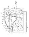
Fig. 1 is a schematic side view illustrating an apparatus for helping to protect a first sized occupant of a vehicle having an uninflated pocket in accordance with an embodiment of the present invention; -
Fig. 2 is a side sectional view ofFig. 1 ; -
Fig. 3 is a front view of the air bag ofFig. 1 ; -
Fig. 4 is a schematic side view illustrating the apparatus ofFig. 1 for helping to protect a second sized occupant of the vehicle; -
Fig. 5 is a schematic illustration of a left panel for constructing the air bag ofFig. 1 ; -
Fig. 6 is a schematic illustration of a right panel for constructing the air bag ofFig. 1 ; -
Fig. 7 is a schematic illustration of a first front panel for constructing the air bag ofFig. 1 ; -
Fig. 8 is a schematic illustration of a second front panel for constructing the air bag ofFig. 1 ; and -
Fig. 9 is a schematic illustration of a panel for a tether for the air bag ofFig. 1 . - An apparatus 10 for helping to protect an
occupant 20 of avehicle 12 includes an inflatable vehicleoccupant protection device 14 in the form of an air bag. In the embodiment illustrated inFig. 1 , theair bag 14 is a passenger frontal air bag that minimizes interaction with theoccupant 20 on apassenger side 24 of thevehicle 12 during inflation. Those skilled in the art will appreciate that the apparatus 10 disclosed herein could be adapted foroccupants 20 on the driver side (not shown) of thevehicle 12 or occupants in rearward rows (not shown) of the vehicle, such as a 2nd row, 3rd row, etc., of the vehicle. - The
air bag 14 may be part of anair bag module 30 that includes an inflator 32 and ahousing 34. Theair bag 14 has a stored condition, indicated by dashed lines inFig. 1 , in which the air bag is folded and placed in thehousing 34. Themodule 30 is mounted to a dash orinstrument panel 36 of thevehicle 12 adjacent avehicle windshield 16. Thehousing 34 helps contain and support theair bag 14 andinflator 32 in theinstrument panel 36. - An
air bag door 40 is releasably connected to theinstrument panel 36 and/or thehousing 34. In a closed condition (not shown), theair bag door 40 forms a cover for themodule 30 and helps enclose theair bag 14 in the stored condition in thehousing 34. Thedoor 40 is movable to an opened condition illustrated inFig. 1 to uncover anopening 44 through which theair bag 14 may be deployed from the stored condition in thehousing 34. Thedoor 40 may be connected to thevehicle 12, e.g., theinstrument panel 36, either directly or through thehousing 34, by means (not shown), such as a plastic hinge portion, a strap or a tether. - The inflator 32 is actuatable to provide inflation fluid to an
inflatable volume 54 of theair bag 14 to deploy the air bag to the inflated condition. The inflator 32 may be of any known type, such as stored gas, solid propellant, augmented, or hybrid. The apparatus 10 includes a sensor, illustrated schematically at 50, for sensing an event for which inflation of theair bag 14 is desired, such as a collision. The inflator 32 is operatively connected to thesensor 50 vialead wires 52. - The
air bag 14 can be constructed of any suitable material, such as nylon (e.g., woven nylon 6-6 yarns), and may be constructed in any suitable manner. For example, theair bag 14 may include one or more pieces or panels of material. If more than one piece or panel is used, the pieces or panels may be interconnected by known means, such as sewing, stitching, ultrasonic welding, heat bonding, or adhesives, to form the air bag. Theair bag 14 may be uncoated, coated with a material, such as a gas impermeable urethane or laminated with a material, such as a gas impermeable film. Theair bag 14 thus may have a gas-tight or substantially gas-tight construction. Those skilled in the art will appreciate that alternative materials, such as polyester yarn, and alternatives coatings, such as silicone, may also be used to construct theair bag 14. - In the embodiment of
Fig. 1 , theinflated air bag 14 deploys from theinstrument panel 36 in an aft direction toward thevehicle seat 22. Theair bag 14 includes afront portion 70 and arear portion 76. In the deployed condition, thefront portion 70 is spaced from theinstrument panel 36 and includes afront panel 72 that is presented towards thevehicle seat 22. Therear portion 76 is positioned adjacent thewindshield 16 andinstrument panel 36 and occupies a substantial portion of the space between the windshield and the instrument panel.Lateral portions front portion 70 to therear portion 76. Thelateral portion 78 is positioned on the inboard side of thevehicle 12 and thelateral portion 80 is positioned on the outboard side of the vehicle. Thelateral portions - A
top portion 90 is positioned adjacent thewindshield 16 and extends from therear portion 76 to thefront portion 70. Abottom portion 92 is positioned adjacent thevehicle seat 22 and extends from therear portion 76 to thefront portion 70. Collectively, thefront portion 70,rear portion 76,lateral portions top portion 90, andbottom portion 92 define aninflatable volume 54 of theair bag 14. - The
air bag 14 includes apocket 100 that extends inward to define acollapsed volume 102 positioned outside of theinflatable volume 54. Theinward pocket 100 has a length L (seeFig. 4 ) extending in an inboard-outboard direction of thevehicle 12 from thelateral portion 78 to thelateral portion 80. In one example, the length L is less than the width of theair bag 14 in the inboard-outboard direction, i.e., thepocket 100 does not extends across the entirefront panel 72 and is therefore spaced from bothlateral portions - The
inward pocket 100 has a depth extending in a fore-aft direction of thevehicle 12 from thefront portion 70 of theair bag 14 towards therear portion 76 and may terminate prior to the rear portion. As best shown inFig. 3 , theinward pocket 100 divides thefront portion 70 of theair bag 14 into a pair of laterally extendinginflatable lobes 110 positioned on opposite sides of the pocket. Alternatively, theinward pocket 100 may extend through theentire air bag 14 from thefront portion 70 to the rear portion 76 (not shown). - A flexible elongated member, such as a
tether 500, interconnects portions of theair bag 14 to help maintain thepocket 100 in the inward condition during inflation of theair bag 14. Thetether 500 acts on thepocket 100 such that the size and/or fore-aft depth of the pocket remains substantially constant when theair bag 14 is fully inflated. Although asingle tether 500 is illustrated inFig. 1 for maintaining thepocket 100 in the inward condition when theair bag 14 if fully inflated, more or fewer tethers may be used to connect one or more portions of the pocket with one ormore portions -
Figs. 5-9 illustrate plan views of component parts used to construct theair bag 14 in accordance with an embodiment of the present invention. The component parts of theair bag 14 include afirst panel 120, asecond panel 220, athird panel 320, and afourth panel 420 interconnected to define theinflatable volume 54 of the air bag. The panel of thetether 500 connects a module side of the air bag 14 (formed by the first andsecond panels 120, 220) to the pocket 100 (formed by the third andfourth panels 320, 420) to determine and maintain the fore-aft depth of the pocket when the air bag is fully inflated. - As shown in
Fig. 5 , thefirst panel 120 extends from afirst end portion 122 to asecond end portion 124 and may be formed from one piece of material. Thefirst panel 120 forms the inboard side of theair bag 14 and is defined by contoured first, second, and thirdperipheral edges first panel 120 may include one ormore openings 132 for accommodating a connection with theair bag module 30, e.g., thehousing 34 and/orinflator 32. - The first, second, and third
peripheral edges air bag 14. In particular, the firstperipheral edge 126 includes afirst notch 134 positioned adjacent theopening 132, asecond notch 136 positioned adjacent the thirdperipheral edge 130, and athird notch 138 positioned between the first and second notches. Similarly, the secondperipheral edge 128 includes afirst notch 140 positioned adjacent theopening 132, asecond notch 142 positioned adjacent the thirdperipheral edge 130, and athird notch 144 positioned between the first and second notches. - The third
peripheral edge 130 includes afirst notch 146 positioned adjacent the firstperipheral edge 126, asecond notch 148 positioned adjacent the secondperipheral edge 128, and third throughsixth notches - Referring still to
Fig. 6 , thesecond panel 220 is similarly shaped to thefirst panel 120. Thesecond portion 76 extends from afirst end portion 222 to asecond end portion 224 and may be formed from one piece of material. Thefirst panel 220 forms the outboard side of theair bag 24 and is defined by contoured first, second, and thirdperipheral edges first panel 220 may include one ormore openings 232 for accommodating a connection with theair bag module 30, e.g., thehousing 34 and/orinflator 32. - The first, second, and third
peripheral edges air bag 14. In particular, the firstperipheral edge 226 includes afirst notch 234 positioned adjacent theopening 232, asecond notch 236 positioned adjacent the thirdperipheral edge 230, and athird notch 238 positioned between the first and second notches. Similarly, the secondperipheral edge 228 includes afirst notch 240 positioned adjacent theopening 232, asecond notch 242 positioned adjacent the thirdperipheral edge 230, and athird notch 244 positioned between the first and second notches. - The third
peripheral edge 230 includes afirst notch 246 positioned adjacent the firstperipheral edge 226, asecond notch 248 positioned adjacent the secondperipheral edge 228, and third throughseventh notches - Although the first and
second panels first panel 120 adjacent to theopenings 132, e.g., portions of the first and secondperipheral edges second panel 220 adjacent to theopenings 232, e.g., portions of the first and secondperipheral edges - As shown in
Fig. 7 , thethird panel 320 has a generally rounded shape and helps form the upper portion of thefront panel 72 of theair bag 14 closer to thewindshield 16. Thethird panel 320 may be formed as one piece of material and extends from afirst end portion 322 to asecond end portion 324. Thethird panel 320 includes a firstperipheral edge 326, a secondperipheral edge 328, and a thirdperipheral edge 330. The secondperipheral edge 328 connects the firstperipheral edge 326 to the thirdperipheral edge 330. The firstperipheral edge 326 has an arcuate or hemispherical contour. The secondperipheral edge 328 is substantially straight. - The third
peripheral edge 330 extends from the secondperipheral edge 328 and away from the firstperipheral edge 326 to form one ormore extensions 344 of material. As shown inFig. 7 , asingle extension 344 extends from the secondperipheral edge 328. Theextension 344 has an arcuate or semicircular contour, although the extension may have alternative shapes, such as square, triangular, rectangular or the like. An indicator ormarker 342 is provided on the thirdperipheral edge 330 at the furthest point from the firstperipheral edge 326. - The first
peripheral edge 326 includes a series of notches for helping to assemble theair bag 14. In particular, the firstperipheral edge 326 includes afirst notch 350 positioned adjacent the secondperipheral edge 328 on one side of theextension 344, asecond notch 352 positioned adjacent the second peripheral edge on the other side of the extension, and third throughsixth notches - As shown in
Fig. 8 , thefourth panel 420 is similarly shaped to thethird panel 320 but larger than thethird panel 320. Thefourth panel 420 has a generally rounded shape and helps to form the lower portion of thefront panel 72 of theair bag 14 closer to thevehicle seat 22. Thefourth panel 420 may be formed as one piece of material and extends from afirst end portion 422 to asecond end portion 424. Thefourth panel 420 includes a firstperipheral edge 426, a secondperipheral edge 428, and a thirdperipheral edge 430. The secondperipheral edge 428 connects the firstperipheral edge 426 to the thirdperipheral edge 430. The firstperipheral edge 426 has an arcuate or hemispherical contour with a greater radius of curvature than the firstperipheral edge 326 of thethird panel 320. The secondperipheral edge 428 is straight and has the same length as the secondperipheral edge 328 of thethird panel 320. - The third
peripheral edge 430 extends from the secondperipheral edge 428 and away from the firstperipheral edge 426 to form one ormore extensions 444 of material. As shown inFig. 8 , asingle extension 444 extends from the secondperipheral edge 428. Theextension 444 has an arcuate or semicircular contour, although the extension may have alternative shapes, such as square, triangular, rectangular or the like. In any case, the extension(s) 444 has the same size and shape as the extension(s) 344 of thethird panel 320. An indicator ormarker 442 is provided on the thirdperipheral edge 430 at the furthest point from the firstperipheral edge 426. - The first
peripheral edge 426 includes a series of notches for helping to assemble theair bag 14. In particular, the firstperipheral edge 426 includes afirst notch 450 positioned adjacent the secondperipheral edge 428 on one side of theextension 444, asecond notch 452 positioned adjacent the secondperipheral edge 428 on the other side of the extension, and third throughsixth notches - Although the third and
fourth panels peripheral edge 330 on thethird panel 320 may be configured and shaped to be integrally formed with portions of the thirdperipheral edge 430 of thefourth panel 420 such that the third and fourth panels may be formed as a single piece of material (not shown). - As shown in
Fig. 9 , thetether 500 may be formed as a one piece panel of material having afirst end portion 502 and asecond end portion 504. Thefirst end portion 502 includes anedge 506 and thesecond end portion 504 includes anedge 510. Thesecond end portion 504 further includes one ormore openings 512 for receiving fasteners (not show) to secure the second end portion to theair bag 14. Although thetether 500 is illustrated as having a substantially rectangular shape, alternative shapes such as square, rectangular, arcuate, etc. may also be used. In any case, thetether 500 does not divide theair bag 14 into separate, sequentially filled chambers. Thetether 500 may be free of openings between thefastener openings 512 and theedge 506 or may include one or more openings (not shown) allowing inflation fluid to flow therethrough. - To assemble the
air bag 14, the firstperipheral edge 126 of thefirst panel 120 is secured to the firstperipheral edge 226 of thesecond panel 220 along a seam (not shown). In particular, the first, second, andthird notches peripheral edge 126 of thefirst panel 120 are aligned with the respective first, second, andthird notches peripheral edge 226 of thesecond panel 220. The seam (not shown) then secures the entire firstperipheral edge 126 of thefirst panel 120 to the entire firstperipheral edge 226 of thesecond panel 220. - The second
peripheral edge 128 of thefirst panel 120 is secured to the secondperipheral edge 228 of thesecond panel 220 along a seam (not shown). In particular, the first, second, andthird notches peripheral edge 128 of thefirst panel 120 are aligned with the respective first, second, andthird notches peripheral edge 228 of thesecond panel 220. The seam (not shown) then secures the entire secondperipheral edge 128 of thefirst panel 120 to the entire secondperipheral edge 228 of thesecond panel 220. - The third and
fourth panels peripheral edges peripheral edges peripheral edges peripheral edges interconnected extensions pocket 100, with the seam interconnecting theperipheral edges Fig. 4 ). The firstperipheral edges interconnected extensions panels interconnected extensions panels 320, 420 (as viewed inFigs. 7 and 8 ). - The interconnected third and
fourth panels second panels peripheral edge 326 of the third panel-320 is secured by a seam to the thirdperipheral edge 130 of thefirst panel 120. In particular, thethird notch 150,fourth notch 152, andfifth notch 154 on the thirdperipheral edge 130 of thefirst panel 120 are aligned with thefourth notch 356,third notch 354, andfirst notch 350, respectively, on the firstperipheral edge 326 of thethird panel 320. This places thefirst notch 146 on the thirdperipheral edge 130 of thefirst panel 120 adjacent a midpoint of the first peripheral 326 of thethird panel 320. - The seam (not shown) then secures the portion of the third
peripheral edge 130 of thefirst panel 120 starting from thefifth notch 154 and ending at the firstperipheral edge 126 to the portion of the firstperipheral edge 326 of thethird panel 320 starting from the secondperipheral edge 328, traveling clockwise along the first peripheral edge 326 (as viewed inFig. 6 ), and ending at the midpoint of the firstperipheral edge 326. - The first
peripheral edge 326 of thethird panel 320 is also secured by a seam to the thirdperipheral edge 230 of thesecond panel 220. In particular, thethird notch 250,fourth notch 252, andfifth notch 254 on the thirdperipheral edge 230 of thesecond panel 220 are aligned with thefifth notch 358,sixth notch 360, andsecond notch 352, respectively, on the firstperipheral edge 326 of thethird panel 320. This places thefirst notch 246 on the thirdperipheral edge 230 of thesecond panel 220 adjacent the midpoint of the first peripheral 326 of thethird panel 320. - The seam (not shown) then secures the portion of the third
peripheral edge 230 of thesecond panel 220 starting from thefifth notch 254 and ending at the firstperipheral edge 226 to the portion of the firstperipheral edge 326 of thethird panel 320 starting from the secondperipheral edge 328, traveling counterclockwise along the first peripheral edge 326 (as viewed inFig. 7 ), and ending at the midpoint of the firstperipheral edge 326. - The first
peripheral edge 426 of thefourth panel 420 is secured by a seam to the thirdperipheral edge 130 of thefirst panel 120. In particular, thesecond notch 148,seventh notch 158,sixth notch 156, andfifth notch 154 on the thirdperipheral edge 130 of thefirst panel 120 are aligned with thefifth notch 458, fourth notch 456,third notch 454, andfirst notch 450, respectively, on the firstperipheral edge 426 of thefourth panel 420. - The seam (not shown) then secures the portion of the third
peripheral edge 130 of thefirst panel 120 starting from thefifth notch 154 and ending at the secondperipheral edge 128 to the portion of the firstperipheral edge 426 of thefourth panel 420 starting from the secondperipheral edge 428, traveling counterclockwise along the first peripheral edge 426 (as viewed inFig. 8 ), and ending at thefifth notch 458. - The first
peripheral edge 426 of thefourth panel 420 is also secured by a seam to the thirdperipheral edge 230 of thesecond panel 220. In particular, thesecond notch 248,seventh notch 258,sixth notch 256, andfifth notch 254 on the thirdperipheral edge 230 of thesecond panel 220 are aligned with thefifth notch 458,sixth notch 460,seventh notch 462, andsecond notch 452, respectively, on the firstperipheral edge 426 of thefourth panel 420. - The seam (not shown) then secures the portion of the third
peripheral edge 230 of thesecond panel 220 starting from thefifth notch 254 and ending at the secondperipheral edge 228 to the portion of the firstperipheral edge 426 of thefourth panel 420 starting from the secondperipheral edge 428, traveling counterclockwise along the first peripheral edge 426 (as viewed inFig. 7 ), and ending at thefifth notch 458. - The interconnected third
peripheral edges extensions edge 506 of thefirst end portion 502 of thetether 500 along a seam (not shown). To this end, theindicator 508 on thetether 500 is aligned with theinterconnected indicators extensions second end portion 504 of thetether 500 is secured to a portion of theair bag 14, e.g., secured to therear portion 76 of the air bag. - Securing the first, second, third, and
fourth panels front portion 70, therear portion 76, thelateral portions top portion 90, and thebottom portion 92 of theair bag 14. The first, second, third, andfourth panels inflatable volume 54 of theair bag 14. - The
tether 500 is sized and configured such that theinflatable volume 54 is formed as a single chamber. To this end, thetether 500 has a narrow width such that fluid exchange between the portion of theair bag 14 above the tether and the portion of the bag below the tether is not impeded and inflation fluid is free to flow simultaneously into allportions tether 500 does not divide theair bag 14 into separate chambers that are sequentially filled upon deployment or have inflation fluid openings or means by which inflation fluid may flow from one portion of the air bag to another portion. As a result, theair bag 14 of the present invention inflates substantially evenly and simultaneously in all directions. - In an embodiment (not shown) with a
pocket 100 traversing the full inboard-outboard width of theair bag 14 and utilizing awide tether 500 to control the depth of the pocket there would be more separation between the portions of the air bag above and below the tether, and an opening(s) provided in the tether to ensure more simultaneous filling of the air bag above and below the tether. - The first, second, third, and
fourth panels pocket 100 and thetether 500 extend inward toward theinflatable volume 54 of theair bag 14 prior to inflation of the air bag. When theair bag 14 is fully inflated, thepocket 100 extends away from thefront panel 72 of the air bag towards therear portion 76 to define thecollapsed volume 102. In other words, thepocket 100 extends inward relative to thefront panel 72 towards therear portion 76 of theair bag 14 when theair bag 14 is fully inflated. - It will be understood that the
interconnected extensions front panel 72 prior to inflation, i.e., thepocket 100 may initially be inverted outward. In this configuration, full deployment of theair bag 14 causes thetether 500 to pull thepocket 100 in the fore direction until the entire pocket extends towards therear portion 76 of the air bag and the desired pocket depth is achieved/maintained. In any case, thetether 500 acts on thepocket 100, i.e., theinterconnected extensions pocket 100 remains substantially constant when theair bag 14 is fully inflated. - Upon sensing the occurrence of an event for which inflation of the
air bag 14 is desired, such as a vehicle collision, thesensor 50 provides a signal to the inflator 32 via thelead wires 52. Upon receiving the signal from thesensor 50, theinflator 32 is actuated and provides inflation fluid to theinflatable volume 54 of theair bag 14 in a known manner. The inflatingair bag 14 exerts a force on thedoor 40, which moves the door to the opened condition. Theair bag 14 inflates from the stored condition to a deployed condition, such as the fully inflated, deployed, and pressurized condition illustrated in solid lines inFig. 1 . Theair bag 14, when inflated, helps protect thevehicle occupant 20 from impacts with parts of thevehicle 12, such as theinstrument panel 36. - In the fully inflated condition shown in
Fig. 1 , thefront portion 70 of theair bag 14 is positioned away from theinstrument panel 36 and thefront panel 72 is presented facing thevehicle seat 22. Thetop portion 90 extends along thewindshield 16 and occupies the space between the windshield and theinstrument panel 36. Thebottom portion 92 extends along theinstrument panel 36 and projects from the instrument panel toward thevehicle seat 22. - The
pocket 100 extends from thefront portion 72 of theair bag 14 towards therear portion 76. The position of thepocket 100 when theair bag 14 is inflated is configured to correspond with the likely or expected position of thehead 21 of a normally sized (50% percentile)occupant 20 when normally positioned on theseat 22. More specifically, thepocket 100 is configured to deploy at a height H (seeFig. 1 ) that is aligned with thehead 21 of anoccupant 20 having average or above-average height. - As the
air bag 14 deploys toward theoccupant 20, thefirst end portion 502 of thetether 500, being secured to the firstperipheral edges pocket 100, move away from theinstrument panel 36 and toward theoccupant 20. Since thesecond end portion 504 of thetether 500 is secured to therear portion 76 adjacent to theinstrument panel 36 the tether provides resistance to movement of thepocket 100 out of the inward condition shown inFigs. 1-2 and thereby helps maintain the size, position, and orientation of the pocket. In one example, thetether 500 acts on thepocket 100 such that theextensions air bag 14 fully deploys. - As shown in
Fig. 3 , when theair bag 14 deploys, thepocket 100 is configured to extend in a substantially horizontal direction along thefront portion 70 of the air bag between thelateral portions pocket 100 may alternatively be configured to extend at an angle relative to thefront portion 70 and/or extend from thelateral portion 70 to thelateral portion 80 of the air bag (not shown) in accordance with the present invention. - The
pocket 100 is sized, shaped, and positioned to tailor the degree of restraint forces upon theoccupant 20 based on the size of the occupant, more specifically, based on the occupant's height. To this end, the height H of thepocket 100 along thefront portion 70 of theair bag 14 helps to ensure a tallersized occupant 20 experiences a greater restraint than a shorter occupant. - An air bag creates two types of forces to restrain an occupant. The first is pressure in the air bag that acts on surface area on the occupant (Force = Pressure x Area). The second is generated by the tension in the air bag fabric, which is proportional to the pressure and the surface area of the air bag. By horizontally dividing the
front panel 72 of theair bag 14, thepocket 100 of the present invention provides a break or split in the fabric tension along thefront portion 70. Consequently, although theair bag 14 includes a singleinflatable volume 54 eachlobe 110 of the air bag provides a separate and independent resistance tooccupant 20 penetration. - Referring to
Fig. 2 , when the normally seated belted orunbelted occupant 20 moves toward theinflated air bag 14, the occupant'shead 21 enters above thepocket 100. Thehead 21 of ataller occupant 20 is positioned above thepocket 100 and therefore engages and interacts with bothlobes 110 of theair bag 14. As a result, the entireinflatable volume 54 of theair bag 14 provides resistance to penetration by the occupant and, thus, the taller, penetratingoccupant 20 experiences relative large restraint forces at thefront panel 72. - Referring to
Fig. 3 , when the shorter, normally seated belted orunbelted occupant 20 moves toward theinflated air bag 14, the occupant'shead 21 is positioned at or below thepocket 100. Theshorter occupant 20 therefore engages and interacts with only thelower lobe 110 of theair bag 14, which deflects relative to the substantially stationaryupper lobe 110. More specifically, although thetether 500 is taught thepocket 100 allows theshorter occupant 20 to engage and interact with thelower lobe 110 without affecting theupper lobe 110. When this occurs, theextension 444 is compressed or shortened under the impact of the penetratingshorter occupant 20. Since theair bag 14 is still pressurized, the inflation fluid in thelower lobe 110 is displaced into theupper lobe 110, causing theextension 344 to move aft in thevehicle 12 towards the occupant and forming anoutward bulge 73 in thefront panel 72. As a result, only the portion of theinflatable volume 54 below the tension break of thepocket 100 provides resistance to penetration by theoccupant 20 and, thus, the shorter penetratingoccupant 20 experiences reduced restraint forces at thefront panel 72 compared to the taller occupant. - Although the
air bag 14 of the present invention has been described as having a particular construction, those skilled in the art will appreciate that modifications to the air bag can be made without deviating from the spirit of the invention. The size, shape, number, and configuration of theextensions pocket 100 and, thus, a particular collapsedvolume 102 that has a particular configuration, e.g., size, shape, and orientation, in order to meet desired performance criteria. For example, one ormore tethers 500 may be configured to be secured to any one ormore portions air bag 14. In particular, tethers 500 may be secured to eachlateral portion air bag 14. Regardless of whether theair bag 14 includes the tether(s) 500, theextensions - From the above description of the invention, those skilled in the art will perceive improvements, changes and modifications. Such improvements, changes and modifications within the skill of the art are intended to be covered by the appended claims.
Claims (13)
- An inflatable vehicle occupant protection device for being inflated with inflation fluid towards a seat of the vehicle, the protection device comprising:a front portion presented towards the vehicle seat and helping to define an inflatable volume, the front portion including a pair of extensions that are overlaid on one another and interconnected to form a pocket defining a collapsed volume outside the inflatable volume, the pocket extending horizontally across the front portion and towards the inflatable volume; anda tether having a first end portion secured to both interconnected extensions and a second end portion secured to a portion of the protection device such that the size of the pocket remains larger than a predetermined amount when the protection device is fully inflated.
- The inflatable vehicle occupant protection device recited in claim 1, wherein the pocket divides the front portion into an upper lobe and a lower lobe, wherein, preferably, the lower lobe provides a first resistance to occupant penetration and the upper lobe provides a second, lower resistance to occupant penetration, and/ or wherein, preferably, the lower lobe provides a first resistance to occupant penetration and the lower lobe and the upper lobe cooperate to provide a second, higher resistance to occupant penetration, and/ or wherein, preferably, the lower lobe is movable relative to the upper lobe.
- The inflatable vehicle occupant protection device recited in claim 1 or 2, wherein the pocket is positioned closer to a top portion than a bottom portion of the protection device, and/ or wherein the pocket extends horizontally across only a part of the front portion, and/ or wherein the front portion is formed by first and second panels that each includes one of the extensions of material forming the pocket, and wherein, preferably, the interconnected extensions are identical and have an inward condition forming the pocket, and/ or wherein, preferably, the first panel includes a first peripheral edge and a second peripheral edge extending from the first peripheral edge to define the extension of the first panel, the second panel including a first peripheral edge and a second peripheral edge extending from the first peripheral edge to define the extension of the second panel, the first peripheral edges being interconnected along a seam and the second peripheral edges being interconnected along a seam to form the pocket.
- The inflatable vehicle occupant protection device recited any one of the claims 1 to 3, wherein the first peripheral edges of the first and second panels are positioned in the front portion of the protection device, and/ or wherein the first peripheral edges are straight, and/ or wherein the first peripheral edges are interconnected along a pair of seams positioned along the front portion on opposite sides of the pocket.
- The inflatable vehicle occupant protection device recited in any one of the claims 1 to 4, wherein the extensions are arcuate or wherein the extensions are hemispherical, and / or wherein the tether is free of openings through which inflation fluid flows.
- The inflatable vehicle occupant protection device recited in any of the claims 1 to 5, wherein vehicle occupant protection device is configured such that, when the protection device is inflated, an upper portion of the protection device above the pocket has a first material tension that provides a first resistance to occupant penetration, a lower portion of the protection device below the pocket having a second material tension that provides a second resistance to occupant penetration, the upper and lower portions having a combined material tension greater than the first material tension and the second material tension.
- The inflatable vehicle occupant protection device recited in any one of the claims 1 to 6, further comprising a rear portion and first and second lateral portions connecting the front portion to the rear portion, wherein inflation fluid flows substantially simultaneously into the first and second lateral portions, the front portion, and the rear portion.
- An inflatable vehicle occupant protection device for being inflated with inflation fluid towards a seat of the vehicle, in particular according to any of the claims 1 to 7, the occupant protection device comprising: a front portion presented towards the vehicle seat and including a pair of extensions that are overlaid on one another and interconnected to form a pocket; a rear portion opposite the front portion; first and second lateral portions interconnecting the front portion and the rear portion to define an inflatable volume, wherein the pocket defines a collapsed volume outside the inflatable volume, the pocket extending preferably horizontally across the front portion and towards the inflatable volume; and a tether having a first end portion secured to both interconnected extensions and a second end portion secured to the rear portion of the protection device such that the size of the pocket remains larger than a predetermined amount when the protection device is fully inflated.
- The inflatable vehicle occupant protection device recited in any of the claims 1 to 8, wherein the pocket divides the front portion into an upper lobe and a lower lobe, wherein, preferably, the lower lobe provides a first resistance to occupant penetration and the upper lobe provides a second, lower resistance to occupant penetration, and/ or wherein, preferably, the lower lobe provides a first resistance to occupant penetration and the lower lobe and the upper lobe cooperate to provide a second, higher resistance to occupant penetration, and/ or wherein, preferably, the lower lobe is movable relative to the upper lobe.
- The inflatable vehicle occupant protection device recited in any of the claims 1 to 9, wherein the pocket is positioned closer to a top portion than a bottom portion of the protection device, and / or wherein the pocket extends horizontally across only a part of the front portion and is spaced from the first and second lateral portions, and/ or wherein the interconnected extensions are identical and have an inward condition forming the pocket, and / or wherein first panel includes a first peripheral edge and a second peripheral edge extending from the first peripheral edge to define the extension of the first panel, the second panel including a first peripheral edge and a second peripheral edge extending from the first peripheral edge to define the extension of the second panel, the first peripheral edges being interconnected along a seam and the second peripheral edges being interconnected along a seam to form the pocket.
- The inflatable vehicle occupant protection device recited in any one of the claims 1 to 10, wherein the first peripheral edges of the first and second panels are positioned in the front portion of the protection device and / or wherein the first peripheral edges are straight, and/ or wherein the first peripheral edges are interconnected along a pair of seams positioned along the front portion on opposite sides of the pocket.
- The inflatable vehicle occupant protection device recited in any of the claims 1 to 11, wherein the extensions are arcuate or wherein the extensions are hemispherical.
- The inflatable vehicle occupant protection device recited in any one of the claims 1 to 12, being configured such that, when the protection device is inflated, an upper portion of the protection device above the pocket has a first material tension that provides a first resistance to occupant penetration, a lower portion of the protection device below the pocket having a second material tension that provides a second resistance to occupant penetration, the upper and lower portions having a combined material tension greater than the first material tension and the second material tension, wherein, preferably, the tether is free of openings through which inflation fluid flows.
Applications Claiming Priority (1)
| Application Number | Priority Date | Filing Date | Title |
|---|---|---|---|
| US14/535,382 US9283920B1 (en) | 2014-11-07 | 2014-11-07 | Air bag with uninflated pocket |
Publications (2)
| Publication Number | Publication Date |
|---|---|
| EP3018014A1 true EP3018014A1 (en) | 2016-05-11 |
| EP3018014B1 EP3018014B1 (en) | 2018-08-29 |
Family
ID=54476645
Family Applications (1)
| Application Number | Title | Priority Date | Filing Date |
|---|---|---|---|
| EP15003167.2A Active EP3018014B1 (en) | 2014-11-07 | 2015-11-05 | Air bag with uninflated pocket |
Country Status (2)
| Country | Link |
|---|---|
| US (1) | US9283920B1 (en) |
| EP (1) | EP3018014B1 (en) |
Families Citing this family (3)
| Publication number | Priority date | Publication date | Assignee | Title |
|---|---|---|---|---|
| US8944462B2 (en) * | 2011-04-15 | 2015-02-03 | Trw Vehicle Safety Systems Inc. | Air bag with uninflated pocket |
| KR102872955B1 (en) * | 2020-06-15 | 2025-10-16 | 현대자동차주식회사 | Air bag device |
| US20250196794A1 (en) * | 2022-01-27 | 2025-06-19 | Akira Koizumi | Airbag device for driver's seat |
Citations (1)
| Publication number | Priority date | Publication date | Assignee | Title |
|---|---|---|---|---|
| US20120261910A1 (en) * | 2011-04-15 | 2012-10-18 | Trw Vehicle Safety Systems Inc. | Air bag with uninflated pocket |
Family Cites Families (68)
| Publication number | Priority date | Publication date | Assignee | Title |
|---|---|---|---|---|
| US3731949A (en) | 1971-05-12 | 1973-05-08 | Allied Chem | Flat bag made of tubular sections |
| US4300894A (en) | 1979-12-03 | 1981-11-17 | General Motors Corporation | Method of making L-shaped inflatable restraint cushion |
| JPH081155Y2 (en) | 1987-12-24 | 1996-01-17 | 日産自動車株式会社 | Vehicle airbag device |
| JP3168591B2 (en) | 1991-03-12 | 2001-05-21 | トヨタ自動車株式会社 | Airbag device |
| US5505485A (en) | 1994-05-23 | 1996-04-09 | Automotive Technologies International, Inc. | Plastic film airbag |
| US5306043A (en) | 1991-10-24 | 1994-04-26 | Trw Vehicle Safety Systems Inc. | Dashboard top mounted vehicle air bag assembly |
| US5308113A (en) | 1992-10-09 | 1994-05-03 | Trw Vehicle Safety Systems Inc. | Airbag inflation-controlling member |
| US5513877A (en) | 1994-12-02 | 1996-05-07 | General Motors Corporation | Vehicle body/supplemental inflation restraint arrangement |
| US5520413A (en) | 1995-09-11 | 1996-05-28 | Morton International, Inc. | Partitioned multi-cell air bag |
| JP3365204B2 (en) | 1996-05-07 | 2003-01-08 | 豊田合成株式会社 | Airbag for airbag equipment |
| DE19643052A1 (en) | 1996-10-18 | 1997-09-04 | Daimler Benz Ag | Airbag for vehicles with fold(s) |
| DE29818946U1 (en) | 1998-10-23 | 1999-02-25 | Trw Repa Gmbh | Airbag for a vehicle occupant restraint system |
| DE19850827A1 (en) | 1998-11-04 | 2000-05-18 | Valeo Klimasysteme Gmbh | Vehicle ventilation system |
| DE19860933A1 (en) | 1998-12-30 | 2000-07-13 | Petri Ag | Airbag module |
| JP4608072B2 (en) | 2000-02-25 | 2011-01-05 | タカタ株式会社 | Airbag device |
| DE50108506D1 (en) | 2000-06-16 | 2006-02-02 | Trw Automotive Safety Sys Gmbh | Passenger airbag protection device |
| US6832780B2 (en) | 2000-07-07 | 2004-12-21 | Takata Corporation | Passenger-seat airbag device |
| JP2002046562A (en) | 2000-08-04 | 2002-02-12 | Takata Corp | Air bag |
| DE20022020U1 (en) | 2000-12-28 | 2001-11-08 | Trw Automotive Safety Sys Gmbh | Airbag module |
| DE20022018U1 (en) | 2000-12-28 | 2001-11-08 | Trw Automotive Safety Sys Gmbh | Airbag restraint |
| JP3918551B2 (en) | 2000-12-28 | 2007-05-23 | 豊田合成株式会社 | Airbag device for passenger seat |
| US6616184B2 (en) | 2001-04-25 | 2003-09-09 | Trw Vehicle Safety Systems Inc. | Vehicle occupant protection apparatus with inflation volume and shape control |
| JP3912144B2 (en) | 2001-05-21 | 2007-05-09 | タカタ株式会社 | Passenger leg protection device for passenger seat |
| JP4826869B2 (en) | 2001-08-10 | 2011-11-30 | タカタ株式会社 | Air bag and air bag device |
| JP4971563B2 (en) | 2001-08-17 | 2012-07-11 | タカタ株式会社 | Airbag device |
| US6786505B2 (en) | 2001-08-17 | 2004-09-07 | Takata Corporation | Airbag device |
| US20060028009A1 (en) | 2002-05-22 | 2006-02-09 | Takata Corporation | Airbag device |
| EP1439096B1 (en) | 2003-01-16 | 2006-10-18 | Ford Global Technologies, LLC | Occupant protection arrangement for a motor vehicle |
| EP1516785A1 (en) | 2003-09-18 | 2005-03-23 | Michael Cohen | Air bags |
| KR100547173B1 (en) | 2003-10-17 | 2006-01-31 | 현대모비스 주식회사 | Cushion of airbag unit |
| JP4158709B2 (en) | 2004-01-27 | 2008-10-01 | 豊田合成株式会社 | Airbag device for passenger seat |
| US7556290B2 (en) | 2006-09-27 | 2009-07-07 | Autoliv Asp, Inc. | Airbag cushion with a laced vent to optionally vent gas for out-of-position conditions |
| US7597355B2 (en) | 2004-04-27 | 2009-10-06 | Autoliv Asp, Inc. | Airbag cushions with optional venting for out-of-position conditions |
| US7614654B2 (en) | 2005-12-07 | 2009-11-10 | Autoliv Asp, Inc. | Airbag cushion with diffuser with cinch tube to vent gas for out-of-position conditions |
| US7722080B2 (en) | 2006-09-27 | 2010-05-25 | Autoliv Asp, Inc. | Airbag cushion with a flap vent to optionally vent gas for out-of-position conditions |
| US7614653B2 (en) | 2006-09-27 | 2009-11-10 | Autoliv Asp, Inc. | Pre-folded airbag cushion with optional venting for out-of-position conditions |
| JP4123270B2 (en) | 2005-11-24 | 2008-07-23 | トヨタ自動車株式会社 | Airbag device |
| US7568729B2 (en) | 2005-12-07 | 2009-08-04 | Autoliv Asp, Inc. | Locking mechanism for a cinch tube of an airbag cushion |
| MX2007003946A (en) | 2006-04-07 | 2008-11-26 | Key Safety Systems Inc | Air bag with groove or recess, open or partially covered. |
| US7607683B2 (en) * | 2006-05-11 | 2009-10-27 | Trw Vehicle Safety Systems Inc. | Vehicle occupant protection apparatus with pocket and method of making same |
| JP4793104B2 (en) | 2006-06-01 | 2011-10-12 | 豊田合成株式会社 | Side airbag device |
| US7748738B2 (en) | 2006-09-27 | 2010-07-06 | Autoliv Asp, Inc. | Airbag cushion with adaptive diffuser for out-of-position conditions |
| US20100102542A1 (en) * | 2007-01-12 | 2010-04-29 | Autoliv Developement Ab | Airbag device |
| EP2117882B1 (en) | 2007-02-14 | 2012-09-19 | Autoliv Development AB | An air-bag for a motor vehicle |
| US7597356B2 (en) | 2007-06-05 | 2009-10-06 | Autoliv Asp, Inc. | Airbag cushions with gas deflectors and optional venting for out-of-position conditions |
| EP2008879B1 (en) | 2007-06-29 | 2012-06-27 | Dalphi Metal España, S.A. | Three-chamber adaptive side airbag |
| US7770926B2 (en) | 2007-08-09 | 2010-08-10 | Autoliv Asp, Inc. | Airbag adaptive venting for out-of-position occupants |
| JP2009061867A (en) | 2007-09-05 | 2009-03-26 | Toyoda Gosei Co Ltd | Air bag for front passenger seat |
| KR101000257B1 (en) | 2007-12-15 | 2010-12-10 | 현대자동차주식회사 | Front passenger's seat airbag structure |
| US8191925B2 (en) | 2008-04-14 | 2012-06-05 | Autoliv Asp, Inc. | Dynamic safety vent |
| JP4992853B2 (en) * | 2008-08-06 | 2012-08-08 | タカタ株式会社 | Airbag device |
| JP2010111331A (en) | 2008-11-07 | 2010-05-20 | Toyoda Gosei Co Ltd | Airbag device for front passenger seat |
| US7946613B2 (en) * | 2009-03-03 | 2011-05-24 | Autoliv Asp, Inc. | Dual chamber airbag cushion |
| US7938445B2 (en) * | 2009-03-03 | 2011-05-10 | Autoliv Asp, Inc. | Dual chamber airbag cushions with a safety vent in the front chamber |
| US8181990B2 (en) | 2009-03-31 | 2012-05-22 | Tk Holdings Inc. | Multiple chamber airbag system |
| DE102009018159A1 (en) | 2009-04-21 | 2010-11-04 | Autoliv Development Ab | Airbag module with an adaptive ventilation opening having gas bag |
| EP2272726B1 (en) | 2009-07-10 | 2015-08-19 | Autoliv Development AB | An air-bag for a motor vehicle |
| GB2472071A (en) * | 2009-07-23 | 2011-01-26 | Ford Global Tech Llc | An airbag assembly |
| KR101071740B1 (en) | 2009-07-31 | 2011-10-11 | 기아자동차주식회사 | Front passebger air bag for vehicles |
| US8371612B2 (en) | 2009-09-17 | 2013-02-12 | Autoliv Asp, Inc. | Inflatable airbag assemblies with lateral and longitudinal tethers |
| KR101136309B1 (en) | 2010-04-23 | 2012-04-19 | 현대모비스 주식회사 | Passenger airbag apparatus |
| US8684404B2 (en) | 2010-10-27 | 2014-04-01 | Trw Vehicle Safety Systems Inc. | Air bag with variable venting |
| US8696022B2 (en) | 2010-10-27 | 2014-04-15 | Trw Vehicle Safety Systems Inc. | Air bag with variable venting |
| EP2686207A1 (en) | 2011-03-14 | 2014-01-22 | TRW Automotive GmbH | Air bag for vehicles |
| CN102390345A (en) | 2011-09-26 | 2012-03-28 | 湖南大学 | Supplemental inflatable restraint system with three parallel drawstrings |
| US8646808B2 (en) | 2012-06-18 | 2014-02-11 | Autoliv Asp, Inc. | Airbag with active vent |
| US8807596B1 (en) | 2013-01-31 | 2014-08-19 | Ford Global Technologies, Llc | Airbag and vehicle passenger restraint system |
| US8882143B2 (en) | 2013-02-08 | 2014-11-11 | Autoliv Asp, Inc. | Airbag with slit vent |
-
2014
- 2014-11-07 US US14/535,382 patent/US9283920B1/en active Active
-
2015
- 2015-11-05 EP EP15003167.2A patent/EP3018014B1/en active Active
Patent Citations (1)
| Publication number | Priority date | Publication date | Assignee | Title |
|---|---|---|---|---|
| US20120261910A1 (en) * | 2011-04-15 | 2012-10-18 | Trw Vehicle Safety Systems Inc. | Air bag with uninflated pocket |
Also Published As
| Publication number | Publication date |
|---|---|
| EP3018014B1 (en) | 2018-08-29 |
| US9283920B1 (en) | 2016-03-15 |
Similar Documents
| Publication | Publication Date | Title |
|---|---|---|
| US9493136B2 (en) | Air bag with uninflated pocket | |
| US11305720B2 (en) | Self-conforming rearseat air bag | |
| EP3209527B1 (en) | Self-conforming airbag | |
| US8876156B2 (en) | Reduced volume air bag | |
| CN111971206B (en) | Vehicle seat | |
| JP6551196B2 (en) | Far-side airbag device and airbag folding method | |
| JP6447392B2 (en) | Side airbag device | |
| US7980592B2 (en) | Bi-lobular air bag | |
| US8172260B2 (en) | Bi-lobular air bag | |
| JP2017036038A (en) | Far side air bag device | |
| CN114763120A (en) | Occupant restraint system | |
| US8764055B2 (en) | Air bag with pleated portion | |
| EP3018014B1 (en) | Air bag with uninflated pocket | |
| EP2746112A1 (en) | An airbag unit | |
| JP6544263B2 (en) | Side airbag device | |
| JP2018016252A (en) | Far side airbag device | |
| US11623599B2 (en) | Airbag with inflator attachment | |
| JP7322551B2 (en) | Airbag, airbag device and vehicle seat | |
| US11772595B2 (en) | Airbag with reinforced tether | |
| US12479394B2 (en) | One-piece fold-flat airbag design | |
| US12617367B2 (en) | Pleated airbag construction | |
| US20250346205A1 (en) | Pleated airbag construction |
Legal Events
| Date | Code | Title | Description |
|---|---|---|---|
| PUAI | Public reference made under article 153(3) epc to a published international application that has entered the european phase |
Free format text: ORIGINAL CODE: 0009012 |
|
| AK | Designated contracting states |
Kind code of ref document: A1 Designated state(s): AL AT BE BG CH CY CZ DE DK EE ES FI FR GB GR HR HU IE IS IT LI LT LU LV MC MK MT NL NO PL PT RO RS SE SI SK SM TR |
|
| AX | Request for extension of the european patent |
Extension state: BA ME |
|
| STAA | Information on the status of an ep patent application or granted ep patent |
Free format text: STATUS: REQUEST FOR EXAMINATION WAS MADE |
|
| 17P | Request for examination filed |
Effective date: 20161111 |
|
| RBV | Designated contracting states (corrected) |
Designated state(s): AL AT BE BG CH CY CZ DE DK EE ES FI FR GB GR HR HU IE IS IT LI LT LU LV MC MK MT NL NO PL PT RO RS SE SI SK SM TR |
|
| STAA | Information on the status of an ep patent application or granted ep patent |
Free format text: STATUS: EXAMINATION IS IN PROGRESS |
|
| 17Q | First examination report despatched |
Effective date: 20170807 |
|
| GRAP | Despatch of communication of intention to grant a patent |
Free format text: ORIGINAL CODE: EPIDOSNIGR1 |
|
| STAA | Information on the status of an ep patent application or granted ep patent |
Free format text: STATUS: GRANT OF PATENT IS INTENDED |
|
| INTG | Intention to grant announced |
Effective date: 20180406 |
|
| GRAS | Grant fee paid |
Free format text: ORIGINAL CODE: EPIDOSNIGR3 |
|
| GRAA | (expected) grant |
Free format text: ORIGINAL CODE: 0009210 |
|
| STAA | Information on the status of an ep patent application or granted ep patent |
Free format text: STATUS: THE PATENT HAS BEEN GRANTED |
|
| AK | Designated contracting states |
Kind code of ref document: B1 Designated state(s): AL AT BE BG CH CY CZ DE DK EE ES FI FR GB GR HR HU IE IS IT LI LT LU LV MC MK MT NL NO PL PT RO RS SE SI SK SM TR |
|
| REG | Reference to a national code |
Ref country code: GB Ref legal event code: FG4D |
|
| REG | Reference to a national code |
Ref country code: CH Ref legal event code: EP |
|
| REG | Reference to a national code |
Ref country code: AT Ref legal event code: REF Ref document number: 1034741 Country of ref document: AT Kind code of ref document: T Effective date: 20180915 |
|
| REG | Reference to a national code |
Ref country code: IE Ref legal event code: FG4D |
|
| REG | Reference to a national code |
Ref country code: DE Ref legal event code: R096 Ref document number: 602015015294 Country of ref document: DE |
|
| REG | Reference to a national code |
Ref country code: NL Ref legal event code: MP Effective date: 20180829 |
|
| REG | Reference to a national code |
Ref country code: LT Ref legal event code: MG4D |
|
| PG25 | Lapsed in a contracting state [announced via postgrant information from national office to epo] |
Ref country code: NL Free format text: LAPSE BECAUSE OF FAILURE TO SUBMIT A TRANSLATION OF THE DESCRIPTION OR TO PAY THE FEE WITHIN THE PRESCRIBED TIME-LIMIT Effective date: 20180829 Ref country code: BG Free format text: LAPSE BECAUSE OF FAILURE TO SUBMIT A TRANSLATION OF THE DESCRIPTION OR TO PAY THE FEE WITHIN THE PRESCRIBED TIME-LIMIT Effective date: 20181129 Ref country code: LT Free format text: LAPSE BECAUSE OF FAILURE TO SUBMIT A TRANSLATION OF THE DESCRIPTION OR TO PAY THE FEE WITHIN THE PRESCRIBED TIME-LIMIT Effective date: 20180829 Ref country code: GR Free format text: LAPSE BECAUSE OF FAILURE TO SUBMIT A TRANSLATION OF THE DESCRIPTION OR TO PAY THE FEE WITHIN THE PRESCRIBED TIME-LIMIT Effective date: 20181130 Ref country code: NO Free format text: LAPSE BECAUSE OF FAILURE TO SUBMIT A TRANSLATION OF THE DESCRIPTION OR TO PAY THE FEE WITHIN THE PRESCRIBED TIME-LIMIT Effective date: 20181129 Ref country code: RS Free format text: LAPSE BECAUSE OF FAILURE TO SUBMIT A TRANSLATION OF THE DESCRIPTION OR TO PAY THE FEE WITHIN THE PRESCRIBED TIME-LIMIT Effective date: 20180829 Ref country code: SE Free format text: LAPSE BECAUSE OF FAILURE TO SUBMIT A TRANSLATION OF THE DESCRIPTION OR TO PAY THE FEE WITHIN THE PRESCRIBED TIME-LIMIT Effective date: 20180829 Ref country code: IS Free format text: LAPSE BECAUSE OF FAILURE TO SUBMIT A TRANSLATION OF THE DESCRIPTION OR TO PAY THE FEE WITHIN THE PRESCRIBED TIME-LIMIT Effective date: 20181229 Ref country code: FI Free format text: LAPSE BECAUSE OF FAILURE TO SUBMIT A TRANSLATION OF THE DESCRIPTION OR TO PAY THE FEE WITHIN THE PRESCRIBED TIME-LIMIT Effective date: 20180829 |
|
| REG | Reference to a national code |
Ref country code: AT Ref legal event code: MK05 Ref document number: 1034741 Country of ref document: AT Kind code of ref document: T Effective date: 20180829 |
|
| PG25 | Lapsed in a contracting state [announced via postgrant information from national office to epo] |
Ref country code: AL Free format text: LAPSE BECAUSE OF FAILURE TO SUBMIT A TRANSLATION OF THE DESCRIPTION OR TO PAY THE FEE WITHIN THE PRESCRIBED TIME-LIMIT Effective date: 20180829 Ref country code: HR Free format text: LAPSE BECAUSE OF FAILURE TO SUBMIT A TRANSLATION OF THE DESCRIPTION OR TO PAY THE FEE WITHIN THE PRESCRIBED TIME-LIMIT Effective date: 20180829 Ref country code: LV Free format text: LAPSE BECAUSE OF FAILURE TO SUBMIT A TRANSLATION OF THE DESCRIPTION OR TO PAY THE FEE WITHIN THE PRESCRIBED TIME-LIMIT Effective date: 20180829 |
|
| PG25 | Lapsed in a contracting state [announced via postgrant information from national office to epo] |
Ref country code: CZ Free format text: LAPSE BECAUSE OF FAILURE TO SUBMIT A TRANSLATION OF THE DESCRIPTION OR TO PAY THE FEE WITHIN THE PRESCRIBED TIME-LIMIT Effective date: 20180829 Ref country code: IT Free format text: LAPSE BECAUSE OF FAILURE TO SUBMIT A TRANSLATION OF THE DESCRIPTION OR TO PAY THE FEE WITHIN THE PRESCRIBED TIME-LIMIT Effective date: 20180829 Ref country code: AT Free format text: LAPSE BECAUSE OF FAILURE TO SUBMIT A TRANSLATION OF THE DESCRIPTION OR TO PAY THE FEE WITHIN THE PRESCRIBED TIME-LIMIT Effective date: 20180829 Ref country code: EE Free format text: LAPSE BECAUSE OF FAILURE TO SUBMIT A TRANSLATION OF THE DESCRIPTION OR TO PAY THE FEE WITHIN THE PRESCRIBED TIME-LIMIT Effective date: 20180829 Ref country code: PL Free format text: LAPSE BECAUSE OF FAILURE TO SUBMIT A TRANSLATION OF THE DESCRIPTION OR TO PAY THE FEE WITHIN THE PRESCRIBED TIME-LIMIT Effective date: 20180829 Ref country code: RO Free format text: LAPSE BECAUSE OF FAILURE TO SUBMIT A TRANSLATION OF THE DESCRIPTION OR TO PAY THE FEE WITHIN THE PRESCRIBED TIME-LIMIT Effective date: 20180829 Ref country code: ES Free format text: LAPSE BECAUSE OF FAILURE TO SUBMIT A TRANSLATION OF THE DESCRIPTION OR TO PAY THE FEE WITHIN THE PRESCRIBED TIME-LIMIT Effective date: 20180829 |
|
| PG25 | Lapsed in a contracting state [announced via postgrant information from national office to epo] |
Ref country code: SK Free format text: LAPSE BECAUSE OF FAILURE TO SUBMIT A TRANSLATION OF THE DESCRIPTION OR TO PAY THE FEE WITHIN THE PRESCRIBED TIME-LIMIT Effective date: 20180829 Ref country code: SM Free format text: LAPSE BECAUSE OF FAILURE TO SUBMIT A TRANSLATION OF THE DESCRIPTION OR TO PAY THE FEE WITHIN THE PRESCRIBED TIME-LIMIT Effective date: 20180829 Ref country code: DK Free format text: LAPSE BECAUSE OF FAILURE TO SUBMIT A TRANSLATION OF THE DESCRIPTION OR TO PAY THE FEE WITHIN THE PRESCRIBED TIME-LIMIT Effective date: 20180829 |
|
| REG | Reference to a national code |
Ref country code: DE Ref legal event code: R097 Ref document number: 602015015294 Country of ref document: DE |
|
| REG | Reference to a national code |
Ref country code: CH Ref legal event code: PL |
|
| PLBE | No opposition filed within time limit |
Free format text: ORIGINAL CODE: 0009261 |
|
| STAA | Information on the status of an ep patent application or granted ep patent |
Free format text: STATUS: NO OPPOSITION FILED WITHIN TIME LIMIT |
|
| PG25 | Lapsed in a contracting state [announced via postgrant information from national office to epo] |
Ref country code: MC Free format text: LAPSE BECAUSE OF FAILURE TO SUBMIT A TRANSLATION OF THE DESCRIPTION OR TO PAY THE FEE WITHIN THE PRESCRIBED TIME-LIMIT Effective date: 20180829 Ref country code: LU Free format text: LAPSE BECAUSE OF NON-PAYMENT OF DUE FEES Effective date: 20181105 |
|
| 26N | No opposition filed |
Effective date: 20190531 |
|
| REG | Reference to a national code |
Ref country code: BE Ref legal event code: MM Effective date: 20181130 |
|
| REG | Reference to a national code |
Ref country code: IE Ref legal event code: MM4A |
|
| PG25 | Lapsed in a contracting state [announced via postgrant information from national office to epo] |
Ref country code: LI Free format text: LAPSE BECAUSE OF NON-PAYMENT OF DUE FEES Effective date: 20181130 Ref country code: CH Free format text: LAPSE BECAUSE OF NON-PAYMENT OF DUE FEES Effective date: 20181130 Ref country code: SI Free format text: LAPSE BECAUSE OF FAILURE TO SUBMIT A TRANSLATION OF THE DESCRIPTION OR TO PAY THE FEE WITHIN THE PRESCRIBED TIME-LIMIT Effective date: 20180829 |
|
| PG25 | Lapsed in a contracting state [announced via postgrant information from national office to epo] |
Ref country code: IE Free format text: LAPSE BECAUSE OF NON-PAYMENT OF DUE FEES Effective date: 20181105 |
|
| PG25 | Lapsed in a contracting state [announced via postgrant information from national office to epo] |
Ref country code: BE Free format text: LAPSE BECAUSE OF NON-PAYMENT OF DUE FEES Effective date: 20181130 |
|
| PG25 | Lapsed in a contracting state [announced via postgrant information from national office to epo] |
Ref country code: MT Free format text: LAPSE BECAUSE OF NON-PAYMENT OF DUE FEES Effective date: 20181105 |
|
| PG25 | Lapsed in a contracting state [announced via postgrant information from national office to epo] |
Ref country code: TR Free format text: LAPSE BECAUSE OF FAILURE TO SUBMIT A TRANSLATION OF THE DESCRIPTION OR TO PAY THE FEE WITHIN THE PRESCRIBED TIME-LIMIT Effective date: 20180829 |
|
| PG25 | Lapsed in a contracting state [announced via postgrant information from national office to epo] |
Ref country code: PT Free format text: LAPSE BECAUSE OF FAILURE TO SUBMIT A TRANSLATION OF THE DESCRIPTION OR TO PAY THE FEE WITHIN THE PRESCRIBED TIME-LIMIT Effective date: 20180829 |
|
| PG25 | Lapsed in a contracting state [announced via postgrant information from national office to epo] |
Ref country code: HU Free format text: LAPSE BECAUSE OF FAILURE TO SUBMIT A TRANSLATION OF THE DESCRIPTION OR TO PAY THE FEE WITHIN THE PRESCRIBED TIME-LIMIT; INVALID AB INITIO Effective date: 20151105 Ref country code: MK Free format text: LAPSE BECAUSE OF NON-PAYMENT OF DUE FEES Effective date: 20180829 Ref country code: CY Free format text: LAPSE BECAUSE OF FAILURE TO SUBMIT A TRANSLATION OF THE DESCRIPTION OR TO PAY THE FEE WITHIN THE PRESCRIBED TIME-LIMIT Effective date: 20180829 |
|
| GBPC | Gb: european patent ceased through non-payment of renewal fee |
Effective date: 20191105 |
|
| PG25 | Lapsed in a contracting state [announced via postgrant information from national office to epo] |
Ref country code: GB Free format text: LAPSE BECAUSE OF NON-PAYMENT OF DUE FEES Effective date: 20191105 |
|
| REG | Reference to a national code |
Ref country code: DE Ref legal event code: R082 Ref document number: 602015015294 Country of ref document: DE Representative=s name: MEHNERT, BERNHARD, DE Ref country code: DE Ref legal event code: R081 Ref document number: 602015015294 Country of ref document: DE Owner name: ZF PASSIVE SAFETY SYSTEMS US INC., WASHINGTON, US Free format text: FORMER OWNER: TRW VEHICLE SAFETY SYSTEMS INC., WASHINGTON, MICH., US |
|
| P01 | Opt-out of the competence of the unified patent court (upc) registered |
Effective date: 20230602 |
|
| PGFP | Annual fee paid to national office [announced via postgrant information from national office to epo] |
Ref country code: FR Payment date: 20250908 Year of fee payment: 11 |
|
| PGFP | Annual fee paid to national office [announced via postgrant information from national office to epo] |
Ref country code: DE Payment date: 20251130 Year of fee payment: 11 |