EP2117882B1 - An air-bag for a motor vehicle - Google Patents
An air-bag for a motor vehicle Download PDFInfo
- Publication number
- EP2117882B1 EP2117882B1 EP07705194A EP07705194A EP2117882B1 EP 2117882 B1 EP2117882 B1 EP 2117882B1 EP 07705194 A EP07705194 A EP 07705194A EP 07705194 A EP07705194 A EP 07705194A EP 2117882 B1 EP2117882 B1 EP 2117882B1
- Authority
- EP
- European Patent Office
- Prior art keywords
- air
- bag
- panel
- bag according
- front surface
- Prior art date
- Legal status (The legal status is an assumption and is not a legal conclusion. Google has not performed a legal analysis and makes no representation as to the accuracy of the status listed.)
- Not-in-force
Links
Images


Classifications
-
- B—PERFORMING OPERATIONS; TRANSPORTING
- B60—VEHICLES IN GENERAL
- B60R—VEHICLES, VEHICLE FITTINGS, OR VEHICLE PARTS, NOT OTHERWISE PROVIDED FOR
- B60R21/00—Arrangements or fittings on vehicles for protecting or preventing injuries to occupants or pedestrians in case of accidents or other traffic risks
- B60R21/02—Occupant safety arrangements or fittings, e.g. crash pads
- B60R21/16—Inflatable occupant restraints or confinements designed to inflate upon impact or impending impact, e.g. air bags
- B60R21/23—Inflatable members
- B60R21/231—Inflatable members characterised by their shape, construction or spatial configuration
- B60R21/2334—Expansion control features
- B60R21/2338—Tethers
-
- B—PERFORMING OPERATIONS; TRANSPORTING
- B60—VEHICLES IN GENERAL
- B60R—VEHICLES, VEHICLE FITTINGS, OR VEHICLE PARTS, NOT OTHERWISE PROVIDED FOR
- B60R21/00—Arrangements or fittings on vehicles for protecting or preventing injuries to occupants or pedestrians in case of accidents or other traffic risks
- B60R2021/003—Arrangements or fittings on vehicles for protecting or preventing injuries to occupants or pedestrians in case of accidents or other traffic risks characterised by occupant or pedestian
- B60R2021/0039—Body parts of the occupant or pedestrian affected by the accident
- B60R2021/0048—Head
-
- B—PERFORMING OPERATIONS; TRANSPORTING
- B60—VEHICLES IN GENERAL
- B60R—VEHICLES, VEHICLE FITTINGS, OR VEHICLE PARTS, NOT OTHERWISE PROVIDED FOR
- B60R21/00—Arrangements or fittings on vehicles for protecting or preventing injuries to occupants or pedestrians in case of accidents or other traffic risks
- B60R21/02—Occupant safety arrangements or fittings, e.g. crash pads
- B60R21/16—Inflatable occupant restraints or confinements designed to inflate upon impact or impending impact, e.g. air bags
- B60R21/23—Inflatable members
- B60R21/231—Inflatable members characterised by their shape, construction or spatial configuration
- B60R21/233—Inflatable members characterised by their shape, construction or spatial configuration comprising a plurality of individual compartments; comprising two or more bag-like members, one within the other
- B60R2021/23308—Inflatable members characterised by their shape, construction or spatial configuration comprising a plurality of individual compartments; comprising two or more bag-like members, one within the other the individual compartments defining the external shape of the bag
-
- B—PERFORMING OPERATIONS; TRANSPORTING
- B60—VEHICLES IN GENERAL
- B60R—VEHICLES, VEHICLE FITTINGS, OR VEHICLE PARTS, NOT OTHERWISE PROVIDED FOR
- B60R21/00—Arrangements or fittings on vehicles for protecting or preventing injuries to occupants or pedestrians in case of accidents or other traffic risks
- B60R21/02—Occupant safety arrangements or fittings, e.g. crash pads
- B60R21/16—Inflatable occupant restraints or confinements designed to inflate upon impact or impending impact, e.g. air bags
- B60R21/23—Inflatable members
- B60R21/231—Inflatable members characterised by their shape, construction or spatial configuration
- B60R21/2334—Expansion control features
- B60R21/2338—Tethers
- B60R2021/23382—Internal tether means
Definitions
- THE PRESENT INVENTION relates to an air-bag for a motor vehicle and, more particularly, relates to an inflatable air-bag of the type suitable for use as a safety device in a motor vehicle.
- Occupant protection arrangements for motor vehicles which comprise an inflatable air-bag are now very well known and serve to reduce, and ideally eliminate, injury to an occupant of a motor vehicle in the event of an accident involving a crash.
- Air-bags of this general type are inflated upon receipt of a signal indicative of a crash situation, the signal being generated by a crash sensor located elsewhere in the motor vehicle, so as to inflate, thereby providing a relatively soft restraint for an occupant of the motor vehicle.
- EP1439096A1 discusses the concept of membrane forces in more detail, and in order to address the problem of potential neck injuries as a result of the membrane forces in an inflating air-bag, proposes an air-bag using seams, straps or ribbons to create a relatively "soft" wavy front surface on the air-bag.
- a problem with the arrangement of EP1439096A1 is that the indentations provided between the adjacent waves of the relatively soft front surface, do not have a constant depth, with the result that the wavy area of the front surface is deeper in the middle portion than at its edges.
- the effect of this is that the membrane force-reducing effects of this prior art arrangement are different in different areas of the front surface of the air-bag, being better in the middle of the front surface than at its periphery.
- EP1439096 discloses an occupant protection arrangement for a motor vehicle comprising at least one inflatable air-bag having a front surface, the front surface facing towards an occupant when said air-bag is inflated and deployed in the case of an emergency.
- the front surface comprises elongated indentations to restrict the membrane forces in the front surface of the air-bag. This achieves the effect that the membrane forces in the air-bag fabric responsible for the imbalance in the loading characteristics between chest-loading and head-loading are significantly reduced or even eliminated, irrespective of the occupant's size.
- the present invention provides an air-bag for a motor-vehicle, the air-bag comprising a plurality of panels attached to one another to define an inflatable chamber having a front surface, a rear part of the inflatable chamber having a gas-inlet configured to receive part of an inflator, the air-bag being characterised in that the front surface is provided with an aperture having a peripheral edge to which is secured an edge of an additional panel, the additional panel having an area greater than the aperture, and being configured so as to define a plurality of adjacent substantially wave-shaped projections having an inflated shape which extends forwardly from the front surface when the air-bag is inflated.
- each said wave-shaped projection defines a wall which extends substantially perpendicularly from the front surface when the air-bag is inflated.
- each said wall is defined by at least one fold, tuck, or dart provided in the additional panel.
- the inflated shape of the or each pair of adjacent wave-shaped projections is created, at least in-part, by a strap having one end attached to part of the additional panel between the two respective wave-shaped projections, the strap being arranged to restrict movement of said part of the additional panel away from the rear part of the inflatable chamber during inflation of the air-bag.
- the aperture, and the additional panel within the aperture are provided in the upper-half of the air-bag when in an inflated state, for impact with the head of an occupant of the motor vehicle.
- each said panel is of fabric material.
- the air-bag comprises a front panel and a rear panel, the front panel defining the front surface.
- the additional panel is orientated relative to the front panel such that the warp and weft yarns of the additional panel lie at an acute angle to the warp and weft yarns of the front panel.
- the front panel is orientated relative to the rear panel such that the warp and weft yarns of the front panel lie at an acute angle to the warp and weft yarns of the rear panel.
- the or each said acute angle is substantially 45 degrees.
- the air-bag is provided with an internal tether arranged to restrict movement of the front surface away from the rear surface during inflation of the air-bag.
- the tether extends between the front and rear panels.
- each wave-shaped projection extends between 50 and 130mm from the front surface when the air-bag is inflated.
- Figure 1 illustrates a sheet of woven fabric material 1, of generally circular form, which will define the front panel of an air-bag (that is the panel of the air-bag presented for impact with an occupant of the motor vehicle upon inflation).
- the warp yarns 4 and the weft yarns 5 of the fabric are arranged so as to run substantially vertically and horizontally respectively (in the orientation of the front panel 2 illustrated in Figure 1 ).
- an aperture 6 is cut from the fabric, the aperture being relatively large and sized so as to cover the region of the front panel 2 which is most likely to be impacted by the head of a 50 percentile male dummy.
- the aperture 6 has a generally trapezoidal form having a relatively short lower edge 7 which runs substantially parallel with the horizontal weft yarns 5 of the fabric, and a relatively long upper edge 8 which is also arranged so as to extend substantially parallel with the weft yarns 5. Connecting the lower and upper edges 7,8 are a pair of side edges 9. It will therefore be seen that the aperture 6 is tapered so as to be narrower at its lower edge 7 than at its upper edge 8.
- FIG 2 illustrates a second fabric sheet 10, which is again of circular form, and which defines a rear panel 11 of the air-bag.
- the rear panel 11 is preferably of substantially equal overall dimension as the front panel 2.
- the fabric of the rear panel 11 is rotated relative to that of the front panel 2 illustrated in Figure 1 such that its warp yarns 13 and the weft yarns 14 lie at an acute angle to the warp yarns 4 and the weft yarns 5 of the fabric defining the front panel 2.
- the warp and weft yarns 13, 14 of the rear panel 11 make an angle of substantially 45 degrees to the warp and weft yarns 4, 5 of the front panel 2.
- the front panel 2 and the rear panel 11 will be attached to one another around their circular peripheral edges, preferably by generally conventional stitching, so as to define an inflatable chamber between the two panels.
- Arranging the warp and weft yarns of the two panels at an angle to one another is useful to ensure that when the air-bag is inflated, it adopts a generally round shape.
- the central region of the rear panel 11 is provided with a gas inlet aperture 15 which is sized and configured to receive part of an inflator (not shown in Figure 2 ), such as a conventional gas generator.
- an inflator such as a conventional gas generator.
- the inflator will be arranged to receive a crash signal from a crash sensor (not shown), the signal being indicative of an accident situation and being effective to actuate the inflator, the inflator thus supplying high-pressure gas through the inlet aperture 15 and into the inflatable chamber defined between the two panels 2, 11.
- Figure 3 illustrates a third sheet of fabric material 16 which will define an additional panel 17 of the air-bag and which, as will be described in more detail below, will be used to close the trapezoidal aperture 6 formed in the front panel 2.
- the additional panel 17 has a generally complimentary trapezoidal shape, with a relatively short lower edge 18 and a relatively long, substantially parallel, upper edge 19, between which extend two side edges 20.
- the fabric sheet 16 defining the additional panel 17 is orientated relative to the fabric of the front panel 2 such that its warp yarns 21 and its weft yarns 22 lie at an acute angle to the warp and weft yarns of the front panel 2.
- the warp and weft yarns 21, 22 of the additional panel 17 make an angle of substantially 45 degrees to the warp and weft yarns 4, 5 of the front panel 2. It will, of course, be appreciated that in such an arrangement, the warp and weft yarns, 21, 22 of the additional panel 17 will effectively lie substantially parallel with the warp and weft yarns 13, 14 of the rear panel 11.
- Each side edge 20 of the additional panel 17 is folded inwardly at a number of positions along its length so as to define a plurality of inwardly-directed darts 23 which are arranged in neighbouring pairs 24.
- Each dart 23 is formed by folding the fabric of the front panel 17 inwardly along a pair of diverging fold lines 25 whereupon the fabric in the region of one fold line 25 is then secured to the fabric in the region of the opposing fold line 25 by stitching, thereby creating an inwardly-directed tuck in the fabric.
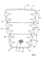
- a three-dimensional shape is imparted to the front panel 17, the shape being shown most clearly in Figure 4 which shows the peripheral edge of the front panel 17 secured to the peripheral edge of the aperture 6 provided in the front panel 2.
- the three-dimensional shape imparted to the additional panel 17 is generally "wavy", and is defined by a series of substantially wave-shaped projections 26 which extend forwardly from the front panel 2.
- Each pair 24 of inwardly-tucked darts 23 serve to create an end wall 27 at the end of a respective wave-shaped projection 26, the end walls 27 having a generally semi-circular profile.
- a fold 28 is defined in the fabric of the additional panel 17, the positions of the folds 28 being illustrated more clearly in Figure 3 .
- the folds 28 extend across substantially the entire width of the additional panel 17.
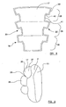
- Figure 5 illustrates a cross-section of the air-bag, taken down a vertical axis of the air-bag, and showing the air-bag having been inflated by inflating gas from an inflator 29 received within the inlet aperture 15. It can therefore be seen that the front panel 2 defines a front surface 2a of the airbag which is presented for impact by an occupant of the motor vehicle.
- An internal tether 30 is provided which is secured, at its foremost end 31, to the fabric defining the front panel 2, generally in the centre of the front panel 2.
- the rearward end 32 of the tether is secured, either to the inflator 29, or to the fabric defining the rear panel 11.
- the purpose of the internal tether 30 is to prevent the front panel 2 extending forwardly relative to the inflator 29 and the rear panel 11 to such a degree that the front panel 2 becomes excessively curved so as to deform the three-dimensional configuration imparted to the additional panel 17 as described above. It is important in operation of the invention that the fabric of the additional panel 17 is not subjected to excessive tensional forces as the air-bag inflates and the internal tether 30 serves to prevent this.
- each strap 33 extends between an anchor point at the rear of the air-bag (preferably provided on the inflator 29 or the rear panel 11) to a respective fold 28 lying between adjacent wave-shaped projections 26. As illustrated most clearly in Figure 6 , each strap 33 has a width w which is less than the overall width W of the respective fold 28 to which it is attached. Furthermore, the forwardmost end of each strap 33 is attached to the central region of its respective fold line 28 such that a region of the fold line 28 extends to either side of the strap 33, having a width L.
- the purpose of the internal straps 33 is to prevent the three-dimensional shape of the front panel 17 being "blown-out".
- the straps 33 thus serve to restrict movement of the central parts of the fold lines 28 away from the rear panel 11 of the air-bag.
- the straps 33 can therefore be considered, at least in-part, to contribute (along with the darts 23) to the creation of the wave-shaped projections 26.
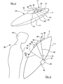
- an occupant 35 of the motor vehicle will move towards the inflated air-bag under the effect of inertia.
- the front panel 2 and the additional panel 17 of the air-bag are arranged so that the occupant's chest/sternum 36 will strike the front panel 2 of the air-bag, below the additional panel 17, whilst the occupant's head will strike the additional panel 17.
- Gas pressure and membrane forces in the front panel 2 will serve to decelerate the occupant's chest/sternum area 26, whilst predominantly gas pressure will serve to decelerate the occupant's head, without a significant contribution from membrane forces within the additional panel 17.
- the wave-shaped projections 26 in the additional panel 17 are simply urged inside out, as illustrated in Figure 7 , by the impact of the occupant's head 37.
- the structure of the additional panel 17 is such that relatively low fabric resistance initially occurs through impact with the occupant's head 37, which means that only very low, if any significant, membrane forces are applied to the head of the occupant.
- the result is that the head of the occupant is allowed to move into the inflated air-bag without experiencing significant fabric resistance until such point as tension is applied on the fabric yarns defining the additional panel 17, which occurs when the additional panel 17 is deformed sufficiently inwardly of the inflating air-bag such that its fabric begins to pull the front panel 2 inwards. It should therefore be appreciated that the longer the length L (i.e.
- each fold line 28 which is not secured to a restraining strap 33
- the later will be the instant at which the front panel 2 is pulled inwardly by the impacted additional panel 17, with the result that it will take longer before the head 37 is decelerated by the membrane forces accumulating within the fabric of the additional panel 17.
- the preferred width w of the restraining straps 33 is 50 mm wide at the point at which it is attached to the respective wave fold 28. Whilst a wider strap, perhaps even as wide as the entire additional panel 17, would serve to maintain the same height h along the entire extent of each projection 26, it would also result in the accumulation of membrane forces from tension within the fabric of the additional panel 17 at an earlier instant.
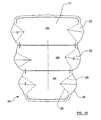
- FIG 8 illustrates an alternative form for the fabric sheet 16 which is used to define the additional panel 17.
- the fabric sheet 16 is again generally trapezoidal, but instead of being manipulated so that parts of its side edges 20 are tucked inwardly in the form of the darts, in this arrangement, the side edges 20 of the fabric sheet 16 are provided with a repeating series of stepped edge regions 38.
- Each edge region 38 comprises an outer edge portion 39 which is stepped inwardly, at 40, at its lower end so as to define an inner edge portion 41.
- the edge regions 38 are manipulated so as to bring together respective outer edge portions 39 and inner edge portions 41, whereupon the outer edge portions 39 are secured to respective inner edge portions 41 by stitching. In this manner, the stepped part 40 of each fold region 38 becomes folded inwardly and is then also stitched up.
- FIG. 9 The resulting three-dimensional shape imparted to the front panel 17 is illustrated in Figure 9 . It will be seen that the front panel 17 again comprises a series of generally wave-shaped projections 26 separated from one another by wave-folds 28, the only significant difference being a slightly different profile for each end wall 27.
- Figure 10 illustrates another alternative form for the fabric sheet 16 which is used to define the front panel 17.
- the fabric sheet 16 is generally similar in many respects to that illustrated in Figure 3 .
- the principal difference in the arrangement of Figure 10 is that a fewer number of darts 23 are created, the darts in this arrangement not being arranged in pairs,and being larger than those of the arrangement in Figure 3 .
- Each dart 23 is again formed by folding a region of fabric inwardly about fold lines 25, whereupon the fabric in the region of the opposing fold lines 25 is then stitched together.
- the end walls 27 of each wave-shaped projection 26 comprise only a single dart 23, whereas in the arrangement of Figure 3 , each end wall 27 incorporated two darts 23 arranged in a pair 24.
- the preferred height h of the wave-shaped projections 26, is somewhere in the range of 50-130 mm. Most preferably, the height h of the waves 26 is between 70 and 110 mm. It is also preferred that the end walls 27 of each wave-shaped projection 26 extend substantially perpendicularly relative to the front panel 2 of the air-bag when the air-bag is inflated.
Description
- THE PRESENT INVENTION relates to an air-bag for a motor vehicle and, more particularly, relates to an inflatable air-bag of the type suitable for use as a safety device in a motor vehicle.
- Occupant protection arrangements for motor vehicles which comprise an inflatable air-bag are now very well known and serve to reduce, and ideally eliminate, injury to an occupant of a motor vehicle in the event of an accident involving a crash. Air-bags of this general type are inflated upon receipt of a signal indicative of a crash situation, the signal being generated by a crash sensor located elsewhere in the motor vehicle, so as to inflate, thereby providing a relatively soft restraint for an occupant of the motor vehicle.
- Research has shown that as an occupant of a motor vehicle impacts with an inflated air-bag, which is typically inflated by a very high pressure of gas, two principal forces serve to act on the occupant. One of these forces results from the pressure of gas within the air-bag, and the other arises from so-called "membrane forces". These membrane forces result from frictional resistance to the relative movement of the warp and weft yarns of the air-bag fabric, as the fabric is subjected to tension across the front surface of the inflate air-bag.
- It has also been found that whilst the chest/sternum area of the human body is relatively resilient to these forces created in an inflating air-bag, due to the natural stiffness of the human body in this area, the head and neck region of the human body is significantly more vulnerable to injury as a result of these forces in an air-bag. It has therefore been found to be desirable to reduce the aforementioned membrane forces in the region of an air-bag which is likely to be impacted by the head of a vehicle occupant so as to reduce the overall force applied to the head and neck region of the occupant, whilst providing a lower region of the air-bag with a configuration susceptible to relatively large membrane forces, the lower region of the air-bag being provided to provide restraint to the chest/sternum region of a vehicle occupant.
-
EP1439096A1 discusses the concept of membrane forces in more detail, and in order to address the problem of potential neck injuries as a result of the membrane forces in an inflating air-bag, proposes an air-bag using seams, straps or ribbons to create a relatively "soft" wavy front surface on the air-bag. However, it has been found that a problem with the arrangement ofEP1439096A1 is that the indentations provided between the adjacent waves of the relatively soft front surface, do not have a constant depth, with the result that the wavy area of the front surface is deeper in the middle portion than at its edges. The effect of this is that the membrane force-reducing effects of this prior art arrangement are different in different areas of the front surface of the air-bag, being better in the middle of the front surface than at its periphery. -
EP1439096 discloses an occupant protection arrangement for a motor vehicle comprising at least one inflatable air-bag having a front surface, the front surface facing towards an occupant when said air-bag is inflated and deployed in the case of an emergency. The front surface comprises elongated indentations to restrict the membrane forces in the front surface of the air-bag. This achieves the effect that the membrane forces in the air-bag fabric responsible for the imbalance in the loading characteristics between chest-loading and head-loading are significantly reduced or even eliminated, irrespective of the occupant's size. - It is an object of the present invention to provide an improved air-bag for a motor vehicle.
- Accordingly, the present invention provides an air-bag for a motor-vehicle, the air-bag comprising a plurality of panels attached to one another to define an inflatable chamber having a front surface, a rear part of the inflatable chamber having a gas-inlet configured to receive part of an inflator, the air-bag being characterised in that the front surface is provided with an aperture having a peripheral edge to which is secured an edge of an additional panel, the additional panel having an area greater than the aperture, and being configured so as to define a plurality of adjacent substantially wave-shaped projections having an inflated shape which extends forwardly from the front surface when the air-bag is inflated.
- Preferably, each said wave-shaped projection defines a wall which extends substantially perpendicularly from the front surface when the air-bag is inflated.
- Conveniently, each said wall is defined by at least one fold, tuck, or dart provided in the additional panel.
- Advantageously, the inflated shape of the or each pair of adjacent wave-shaped projections is created, at least in-part, by a strap having one end attached to part of the additional panel between the two respective wave-shaped projections, the strap being arranged to restrict movement of said part of the additional panel away from the rear part of the inflatable chamber during inflation of the air-bag.
- Conveniently, the aperture, and the additional panel within the aperture, are provided in the upper-half of the air-bag when in an inflated state, for impact with the head of an occupant of the motor vehicle.
- Preferably, each said panel is of fabric material.
- Conveniently, the air-bag comprises a front panel and a rear panel, the front panel defining the front surface.
- Advantageously, the additional panel is orientated relative to the front panel such that the warp and weft yarns of the additional panel lie at an acute angle to the warp and weft yarns of the front panel.
- Conveniently, the front panel is orientated relative to the rear panel such that the warp and weft yarns of the front panel lie at an acute angle to the warp and weft yarns of the rear panel.
- Preferably, the or each said acute angle is substantially 45 degrees.
- Advantageously, the air-bag is provided with an internal tether arranged to restrict movement of the front surface away from the rear surface during inflation of the air-bag.
- Conveniently, the tether extends between the front and rear panels.
- Preferably, each wave-shaped projection extends between 50 and 130mm from the front surface when the air-bag is inflated.
- So that the invention may be more readily understood, and so that further features thereof may be appreciated, embodiments of the invention will now be described, by way of example, with reference to the accompanying drawings, in which:-
-
FIGURE 1 is a plan view from above of a layer of fabric material forming the front panel of an air-bag in accordance with the present invention; -
FIGURE 2 is a plan view from above of a layer of fabric material forming the rear panel of the air-bag; -
FIGURE 3 is a plan view of a sheet of fabric material which forms an additional panel of the air-bag; -
FIGURE 4 is a perspective view from the front and one side, illustrating an air-bag formed from the three panels ofFigures 1 to 3 ; -
FIGURE 5 is a schematic transverse cross-sectional view through the air-bag arrangement illustrated inFigure 4 ; -
FIGURE 6 is a schematic cross-sectional view through the air-bag, viewed from above, showing the air-bag in an inflated condition; -
FIGURE 7 is a view corresponding generally to that ofFigure 6 , illustrating a head of a vehicle occupant impacting with the air-bag; -
FIGURE 8 illustrates an alternative form for the additional panel; -
FIGURE 9 is a side view of an air-bag incorporating the side panel ofFigure 8 , in an inflated condition; and -
FIGURE 10 illustrates another alternative form for the additional panel. - Referring initially to
Figures 1 and 2 of the drawings, the invention will now be described in more detail. -
Figure 1 illustrates a sheet of woven fabric material 1, of generally circular form, which will define the front panel of an air-bag (that is the panel of the air-bag presented for impact with an occupant of the motor vehicle upon inflation). As illustrated schematically at 3, thewarp yarns 4 and theweft yarns 5 of the fabric are arranged so as to run substantially vertically and horizontally respectively (in the orientation of thefront panel 2 illustrated inFigure 1 ). In the upper half of thefront panel 2, anaperture 6 is cut from the fabric, the aperture being relatively large and sized so as to cover the region of thefront panel 2 which is most likely to be impacted by the head of a 50 percentile male dummy. - In the preferred configuration illustrated in
Figure 1 , theaperture 6 has a generally trapezoidal form having a relatively shortlower edge 7 which runs substantially parallel with thehorizontal weft yarns 5 of the fabric, and a relatively longupper edge 8 which is also arranged so as to extend substantially parallel with theweft yarns 5. Connecting the lower andupper edges side edges 9. It will therefore be seen that theaperture 6 is tapered so as to be narrower at itslower edge 7 than at itsupper edge 8. -
Figure 2 illustrates asecond fabric sheet 10, which is again of circular form, and which defines arear panel 11 of the air-bag. Therear panel 11 is preferably of substantially equal overall dimension as thefront panel 2. As illustrated schematically at 12, the fabric of therear panel 11 is rotated relative to that of thefront panel 2 illustrated inFigure 1 such that itswarp yarns 13 and theweft yarns 14 lie at an acute angle to thewarp yarns 4 and theweft yarns 5 of the fabric defining thefront panel 2. In the preferred arrangement, the warp andweft yarns rear panel 11 make an angle of substantially 45 degrees to the warp andweft yarns front panel 2. - In order to fabricate the air-bag of the present invention, the
front panel 2 and therear panel 11 will be attached to one another around their circular peripheral edges, preferably by generally conventional stitching, so as to define an inflatable chamber between the two panels. Arranging the warp and weft yarns of the two panels at an angle to one another is useful to ensure that when the air-bag is inflated, it adopts a generally round shape. - The central region of the
rear panel 11 is provided with agas inlet aperture 15 which is sized and configured to receive part of an inflator (not shown inFigure 2 ), such as a conventional gas generator. When the air-bag arrangement is installed in a motor vehicle, the inflator will be arranged to receive a crash signal from a crash sensor (not shown), the signal being indicative of an accident situation and being effective to actuate the inflator, the inflator thus supplying high-pressure gas through theinlet aperture 15 and into the inflatable chamber defined between the twopanels -
Figure 3 illustrates a third sheet offabric material 16 which will define anadditional panel 17 of the air-bag and which, as will be described in more detail below, will be used to close thetrapezoidal aperture 6 formed in thefront panel 2. As such, theadditional panel 17 has a generally complimentary trapezoidal shape, with a relatively shortlower edge 18 and a relatively long, substantially parallel,upper edge 19, between which extend twoside edges 20. - The
fabric sheet 16 defining theadditional panel 17 is orientated relative to the fabric of thefront panel 2 such that itswarp yarns 21 and itsweft yarns 22 lie at an acute angle to the warp and weft yarns of thefront panel 2. Most preferably, the warp andweft yarns additional panel 17 make an angle of substantially 45 degrees to the warp andweft yarns front panel 2. It will, of course, be appreciated that in such an arrangement, the warp and weft yarns, 21, 22 of theadditional panel 17 will effectively lie substantially parallel with the warp andweft yarns rear panel 11. It has been found that arranging the warp andweft yarns additional panel 17 so as to lie at an acute angle to the warp andweft yarns front panel 2 allows a greater degree of movement of the warp andweft yarns additional panel 17 to stretch by a greater degree when it is impacted by the head of an occupant. - Each
side edge 20 of theadditional panel 17 is folded inwardly at a number of positions along its length so as to define a plurality of inwardly-directeddarts 23 which are arranged in neighbouringpairs 24. Eachdart 23 is formed by folding the fabric of thefront panel 17 inwardly along a pair of divergingfold lines 25 whereupon the fabric in the region of onefold line 25 is then secured to the fabric in the region of theopposing fold line 25 by stitching, thereby creating an inwardly-directed tuck in the fabric. - When all of the
darts 25 have been folded and stitched up as described above, a three-dimensional shape is imparted to thefront panel 17, the shape being shown most clearly inFigure 4 which shows the peripheral edge of thefront panel 17 secured to the peripheral edge of theaperture 6 provided in thefront panel 2. The three-dimensional shape imparted to theadditional panel 17 is generally "wavy", and is defined by a series of substantially wave-shaped projections 26 which extend forwardly from thefront panel 2. Eachpair 24 of inwardly-tucked darts 23 serve to create anend wall 27 at the end of a respective wave-shaped projection 26, theend walls 27 having a generally semi-circular profile. - Between neighbouring wave-shaped
projections 26, afold 28 is defined in the fabric of theadditional panel 17, the positions of thefolds 28 being illustrated more clearly inFigure 3 . Thefolds 28 extend across substantially the entire width of theadditional panel 17. -
Figure 5 illustrates a cross-section of the air-bag, taken down a vertical axis of the air-bag, and showing the air-bag having been inflated by inflating gas from an inflator 29 received within theinlet aperture 15. It can therefore be seen that thefront panel 2 defines afront surface 2a of the airbag which is presented for impact by an occupant of the motor vehicle. - An
internal tether 30 is provided which is secured, at itsforemost end 31, to the fabric defining thefront panel 2, generally in the centre of thefront panel 2. Therearward end 32 of the tether is secured, either to the inflator 29, or to the fabric defining therear panel 11. The purpose of theinternal tether 30 is to prevent thefront panel 2 extending forwardly relative to the inflator 29 and therear panel 11 to such a degree that thefront panel 2 becomes excessively curved so as to deform the three-dimensional configuration imparted to theadditional panel 17 as described above. It is important in operation of the invention that the fabric of theadditional panel 17 is not subjected to excessive tensional forces as the air-bag inflates and theinternal tether 30 serves to prevent this. - Also provided within the internal chamber of the air-bag are a number of
straps 33. Eachstrap 33 extends between an anchor point at the rear of the air-bag (preferably provided on the inflator 29 or the rear panel 11) to arespective fold 28 lying between adjacent wave-shapedprojections 26. As illustrated most clearly inFigure 6 , eachstrap 33 has a width w which is less than the overall width W of therespective fold 28 to which it is attached. Furthermore, the forwardmost end of eachstrap 33 is attached to the central region of itsrespective fold line 28 such that a region of thefold line 28 extends to either side of thestrap 33, having a width L. - The purpose of the
internal straps 33 is to prevent the three-dimensional shape of thefront panel 17 being "blown-out". Thestraps 33 thus serve to restrict movement of the central parts of the fold lines 28 away from therear panel 11 of the air-bag. Thestraps 33 can therefore be considered, at least in-part, to contribute (along with the darts 23) to the creation of the wave-shapedprojections 26. - In a collision involving a motor vehicle equipped with the air-bag of the present invention, an
occupant 35 of the motor vehicle will move towards the inflated air-bag under the effect of inertia. Thefront panel 2 and theadditional panel 17 of the air-bag are arranged so that the occupant's chest/sternum 36 will strike thefront panel 2 of the air-bag, below theadditional panel 17, whilst the occupant's head will strike theadditional panel 17. Gas pressure and membrane forces in thefront panel 2 will serve to decelerate the occupant's chest/sternum area 26, whilst predominantly gas pressure will serve to decelerate the occupant's head, without a significant contribution from membrane forces within theadditional panel 17. The wave-shapedprojections 26 in theadditional panel 17 are simply urged inside out, as illustrated inFigure 7 , by the impact of the occupant'shead 37. - The structure of the
additional panel 17 is such that relatively low fabric resistance initially occurs through impact with the occupant'shead 37, which means that only very low, if any significant, membrane forces are applied to the head of the occupant. The result is that the head of the occupant is allowed to move into the inflated air-bag without experiencing significant fabric resistance until such point as tension is applied on the fabric yarns defining theadditional panel 17, which occurs when theadditional panel 17 is deformed sufficiently inwardly of the inflating air-bag such that its fabric begins to pull thefront panel 2 inwards. It should therefore be appreciated that the longer the length L (i.e. the extent of eachfold line 28 which is not secured to a restraining strap 33), then the later will be the instant at which thefront panel 2 is pulled inwardly by the impactedadditional panel 17, with the result that it will take longer before thehead 37 is decelerated by the membrane forces accumulating within the fabric of theadditional panel 17. Through experiment, it has been found that the preferred width w of the restraining straps 33 is 50 mm wide at the point at which it is attached to therespective wave fold 28. Whilst a wider strap, perhaps even as wide as the entireadditional panel 17, would serve to maintain the same height h along the entire extent of eachprojection 26, it would also result in the accumulation of membrane forces from tension within the fabric of theadditional panel 17 at an earlier instant. -
Figure 8 illustrates an alternative form for thefabric sheet 16 which is used to define theadditional panel 17. In this arrangement, thefabric sheet 16 is again generally trapezoidal, but instead of being manipulated so that parts of its side edges 20 are tucked inwardly in the form of the darts, in this arrangement, the side edges 20 of thefabric sheet 16 are provided with a repeating series of steppededge regions 38. Eachedge region 38 comprises anouter edge portion 39 which is stepped inwardly, at 40, at its lower end so as to define aninner edge portion 41. In order to impart the necessary three-dimensional shape to theadditional panel 17, theedge regions 38 are manipulated so as to bring together respectiveouter edge portions 39 andinner edge portions 41, whereupon theouter edge portions 39 are secured to respectiveinner edge portions 41 by stitching. In this manner, the steppedpart 40 of eachfold region 38 becomes folded inwardly and is then also stitched up. - The resulting three-dimensional shape imparted to the
front panel 17 is illustrated inFigure 9 . It will be seen that thefront panel 17 again comprises a series of generally wave-shapedprojections 26 separated from one another by wave-folds 28, the only significant difference being a slightly different profile for eachend wall 27. -
Figure 10 illustrates another alternative form for thefabric sheet 16 which is used to define thefront panel 17. In this arrangement, thefabric sheet 16 is generally similar in many respects to that illustrated inFigure 3 . The principal difference in the arrangement ofFigure 10 is that a fewer number ofdarts 23 are created, the darts in this arrangement not being arranged in pairs,and being larger than those of the arrangement inFigure 3 . Eachdart 23 is again formed by folding a region of fabric inwardly aboutfold lines 25, whereupon the fabric in the region of the opposingfold lines 25 is then stitched together. In this arrangement, theend walls 27 of each wave-shapedprojection 26 comprise only asingle dart 23, whereas in the arrangement ofFigure 3 , eachend wall 27 incorporated twodarts 23 arranged in apair 24. - Through experiment, it has been found that the preferred height h of the wave-shaped
projections 26, is somewhere in the range of 50-130 mm. Most preferably, the height h of thewaves 26 is between 70 and 110 mm. It is also preferred that theend walls 27 of each wave-shapedprojection 26 extend substantially perpendicularly relative to thefront panel 2 of the air-bag when the air-bag is inflated. - When used in this specification and claims, the terms "comprises" and "comprising" and variations thereof mean that the specified features, steps or integers are included. The terms are not to be interpreted to exclude the presence of other features, steps or components.
Claims (13)
- An air-bag for a motor-vehicle, the air-bag comprising a plurality of panels (2,11) attached to one another to define an inflatable chamber having a front surface (2a), a rear part (11) of the inflatable chamber having a gas-inlet (15) configured to receive part of an inflator (29), the air-bag being characterised in that the front surface (2a) is provided with an aperture (6) having a peripheral edge to which is secured an edge of an additional panel (17), the additional panel (17) having an area greater than the aperture (6), and being configured so as to define a plurality of adjacent substantially wave-shaped projections (26) having an inflated shape which extends forwardly from the front surface (2a) when the air-bag is inflated.
- An air-bag according to claim 1, wherein each said wave-shaped projection (26) defines a wall (27) which extends substantially perpendicularly from the front surface (2a) when the air-bag is inflated.
- An air-bag according to claim 2, wherein each said wall (27) is defined by at least one fold, tuck, or dart provided in the additional panel (17)
- An air-bag according to any preceding claim, wherein the inflated shape of the or each pair of adjacent wave-shaped projections (26) is created, at least in-part, by a strap (33) having one end attached to part (28) of the additional panel (17) between the two respective wave-shaped projections (26), the strap (33) being arranged to restrict movement of said part (28) of the additional panel (17) away from the rear part (11) of the inflatable chamber during inflation of the air-bag.
- An air-bag according to any preceding claim, wherein the aperture (6), and the additional panel (17) within the aperture, are provided in the upper-half of the air-bag when in an inflated state, for impact with the head (37) of an occupant (35) of the motor vehicle.
- An air-bag according to any preceding claim, comprising a front panel (2) and a rear panel (11), the front panel (2) defining the front surface (2a).
- An air-bag according to any preceding claim, wherein each said panel (2,11,17) is of fabric material.
- An air-bag according to claim 7 as dependant upon claim 6, wherein the additional panel (17) is orientated relative to the front panel (2) such that the warp (21) and weft (22) yarns of the additional panel (17) lie at an acute angle to the warp (4) and weft (5) yarns of the front panel (2).
- An air-bag according to claim 7 as dependant upon claim'6, or claim 8, wherein the front panel (2) is orientated relative to the rear panel (11) such that the warp (4) and weft (5) yarns of the front panel (2) lie at an acute angle to the warp (13) and weft (14) yarns of the rear panel (11).
- An air-bag according to claim 8 or claim 9, wherein the or each said acute angle is substantially 45 degrees.
- An air-bag according to any preceding claim, provided with an internal tether (30) arranged to restrict movement of the front surface (2a) away from the rear part (11) of the inflatable chamber during inflation of the air-bag.
- An air-bag according to claim11 as dependant upon claim 6, wherein the tether (30) extends between the front (2) and rear panels (11).
- An air-bag according to any preceding claim, wherein each wave-shaped projection (26) extends between 50 and 130mm from the front surface (2a) when the air-bag is inflated.
Applications Claiming Priority (1)
| Application Number | Priority Date | Filing Date | Title |
|---|---|---|---|
| PCT/GB2007/000507 WO2008099130A1 (en) | 2007-02-14 | 2007-02-14 | An air-bag for a motor vehicle |
Publications (2)
| Publication Number | Publication Date |
|---|---|
| EP2117882A1 EP2117882A1 (en) | 2009-11-18 |
| EP2117882B1 true EP2117882B1 (en) | 2012-09-19 |
Family
ID=38572825
Family Applications (1)
| Application Number | Title | Priority Date | Filing Date |
|---|---|---|---|
| EP07705194A Not-in-force EP2117882B1 (en) | 2007-02-14 | 2007-02-14 | An air-bag for a motor vehicle |
Country Status (4)
| Country | Link |
|---|---|
| US (1) | US8215671B2 (en) |
| EP (1) | EP2117882B1 (en) |
| JP (1) | JP4940312B2 (en) |
| WO (1) | WO2008099130A1 (en) |
Cited By (2)
| Publication number | Priority date | Publication date | Assignee | Title |
|---|---|---|---|---|
| DE102016119387A1 (en) * | 2016-10-12 | 2018-04-12 | Trw Automotive Gmbh | Front airbag for a vehicle occupant |
| US10513239B2 (en) | 2015-05-28 | 2019-12-24 | Joyson Safety Systems Germany Gmbh | Gas bag for an airbag module |
Families Citing this family (14)
| Publication number | Priority date | Publication date | Assignee | Title |
|---|---|---|---|---|
| EP2272726B1 (en) | 2009-07-10 | 2015-08-19 | Autoliv Development AB | An air-bag for a motor vehicle |
| US8356834B1 (en) * | 2011-08-29 | 2013-01-22 | Yaw Shin Liao | Airbag with bent head portion and a repeated sealing and filling effect |
| DE102012000023A1 (en) * | 2012-01-03 | 2013-07-04 | Christoph Traxler | Airbag i.e. side airbag system, for use between driver and driver's door or front passenger and passenger door in motor vehicle, has sub-region provided with layer that is pulled from channels to be opened from outer side of layer |
| US9162645B2 (en) | 2013-12-20 | 2015-10-20 | Ford Global Technologies, Llc | High pressure airbag for oblique impact modes |
| EP3181412B1 (en) | 2014-02-20 | 2018-08-08 | Dalphi Metal España, S.A. | Airbag |
| US9561774B2 (en) | 2014-04-24 | 2017-02-07 | Ford Global Technologies, Llc | Winged driver airbag |
| US9713998B2 (en) * | 2014-04-24 | 2017-07-25 | Ford Global Technologies, Llc | Corrugated passenger airbag |
| US9969349B2 (en) | 2014-04-24 | 2018-05-15 | Ford Global Technologies, Llc | Passenger airbag with extended base |
| US9283920B1 (en) | 2014-11-07 | 2016-03-15 | Trw Vehicle Safety Systems Inc. | Air bag with uninflated pocket |
| JP6575448B2 (en) * | 2016-06-30 | 2019-09-18 | 豊田合成株式会社 | Airbag device |
| GB2554895B (en) * | 2016-10-12 | 2018-10-10 | Ford Global Tech Llc | Vehicle loadspace floor system having a deployable seat |
| DE102018109382A1 (en) | 2018-04-19 | 2019-10-24 | Trw Automotive Gmbh | Frontal airbag |
| KR102064843B1 (en) * | 2018-04-23 | 2020-01-10 | 아우토리브 디벨롭먼트 아베 | Airbag apparatus of vehicle |
| CN111845615B (en) * | 2019-04-29 | 2023-08-22 | 奥托立夫开发公司 | Airbag and vehicle |
Family Cites Families (41)
| Publication number | Priority date | Publication date | Assignee | Title |
|---|---|---|---|---|
| BE794296A (en) * | 1972-01-19 | 1973-07-19 | Des Soc Nat | NEW INFLATABLE CUSHION SAFETY DEVICE, ESPECIALLY FOR UATOMOBILE VEHICLES |
| SE397312B (en) * | 1973-02-12 | 1977-10-31 | Inventing Ab | METHOD OF MANUFACTURING SHOCK-ENSURING PROTECTION FOR VEHICLE PASSENGERS |
| EP0483366A4 (en) * | 1990-04-27 | 1993-08-25 | Daicel Chemical Industries, Ltd. | Air bag type rider-protective device |
| US7338069B2 (en) * | 2004-04-02 | 2008-03-04 | Automotive Technologies International, Inc. | Airbags with internal valves |
| US5732973A (en) * | 1996-07-22 | 1998-03-31 | Trw Vehicle Safety Systems Inc. | Tuck folded air bag |
| US5901979A (en) * | 1997-05-06 | 1999-05-11 | Autoliv Asp, Inc. | Airbag cushion and mounting therefor |
| US5927748A (en) * | 1997-06-26 | 1999-07-27 | O'driscoll; Peter | Multi-stage inflatable bag for vehicular safety systems |
| JP4129758B2 (en) * | 1998-08-10 | 2008-08-06 | 俊毅 内田 | Airbag device |
| JP4608072B2 (en) * | 2000-02-25 | 2011-01-05 | タカタ株式会社 | Airbag device |
| US20020149187A1 (en) * | 2001-04-11 | 2002-10-17 | Holtz Kimberlee D. | Soft-surface inflatable knee bolster airbag |
| US6786505B2 (en) * | 2001-08-17 | 2004-09-07 | Takata Corporation | Airbag device |
| CA2361732A1 (en) | 2001-10-29 | 2003-04-29 | Minh H. Le | Airbag surface redesign |
| JP2003182500A (en) * | 2001-12-25 | 2003-07-03 | Takata Corp | Occupant crash protection device |
| JP3855775B2 (en) * | 2002-01-16 | 2006-12-13 | 東レ株式会社 | Coat airbag base fabric |
| US6851706B2 (en) * | 2002-03-21 | 2005-02-08 | Autoliv Asp, Inc. | Side-impact, variable thickness vehicular airbag |
| JP3948332B2 (en) * | 2002-04-15 | 2007-07-25 | タカタ株式会社 | Crew protection device |
| JP2003327184A (en) | 2002-05-15 | 2003-11-19 | Takata Corp | Air bag device for motorcycle, manufacturing method of air bag device for motorcycle and motorcycle with air bag device |
| JP3900008B2 (en) * | 2002-05-22 | 2007-04-04 | 豊田合成株式会社 | Airbag |
| JP2004210257A (en) * | 2002-12-18 | 2004-07-29 | Takata Corp | Head part protection air bag and head part protection air bag device |
| EP1439096B1 (en) | 2003-01-16 | 2006-10-18 | Ford Global Technologies, LLC | Occupant protection arrangement for a motor vehicle |
| US7152877B2 (en) * | 2003-01-24 | 2006-12-26 | Takata Corporation | Airbag and airbag apparatus |
| JP4367119B2 (en) * | 2003-05-07 | 2009-11-18 | タカタ株式会社 | Air bag and air bag device |
| JP2005126041A (en) * | 2003-07-31 | 2005-05-19 | Takata Corp | Occupant protection device |
| EP1516785A1 (en) | 2003-09-18 | 2005-03-23 | Michael Cohen | Air bags |
| DE102004009013B4 (en) * | 2004-02-25 | 2006-03-16 | Trw Automotive Gmbh | Side impact restraint device |
| JP4604765B2 (en) * | 2004-03-08 | 2011-01-05 | タカタ株式会社 | Airbag device |
| US7354063B2 (en) * | 2004-03-09 | 2008-04-08 | Milliken & Company | Airbag structure |
| WO2006024472A1 (en) * | 2004-09-01 | 2006-03-09 | Autoliv Development Ab | Airbag and a motor vehicle |
| CN1259207C (en) * | 2004-11-30 | 2006-06-14 | 湖南大学 | Laminated pipe safety air bag |
| CN101698402B (en) * | 2005-07-07 | 2013-09-11 | 芦森工业株式会社 | Safe airbag device |
| JP4347281B2 (en) * | 2005-08-29 | 2009-10-21 | トヨタ自動車株式会社 | Passenger airbag |
| US7325830B2 (en) * | 2005-09-05 | 2008-02-05 | Honda Motor Co., Ltd. | Airbag device for vehicles |
| DE102005049209A1 (en) * | 2005-10-07 | 2007-04-12 | Takata-Petri Ag | Airbag arrangement for an airbag module of a motor vehicle |
| JP2007230501A (en) * | 2006-03-03 | 2007-09-13 | Toyoda Gosei Co Ltd | Airbag device for front passenger seat |
| US7758069B2 (en) * | 2006-05-18 | 2010-07-20 | Autoliv Asp, Inc. | Knee airbag and restraint system for suppressing deployment of head/torso airbag |
| DE102006027588A1 (en) * | 2006-06-14 | 2007-12-20 | Trw Automotive Gmbh | Front seat passenger sided-passenger protection device for motor vehicle, has catch belt with fastening section that is fastened at front wall of gas bag, where fastening section vertically extends in unfolded condition of gas bag |
| JP4337850B2 (en) * | 2006-08-25 | 2009-09-30 | トヨタ自動車株式会社 | Airbag device for driver's seat |
| JP5104234B2 (en) * | 2007-11-09 | 2012-12-19 | タカタ株式会社 | Air bag and air bag device |
| EP2072348B1 (en) * | 2007-12-18 | 2016-10-05 | Autoliv Development AB | Knee airbag and method of folding the same |
| US7654561B2 (en) * | 2008-03-01 | 2010-02-02 | Delphi Technologies, Inc. | Inflatable cushion for an airbag module |
| KR101020551B1 (en) * | 2008-11-10 | 2011-03-09 | 현대자동차주식회사 | Cushion of exterior air-bag for vehicles and apparatus thereof |
-
2007
- 2007-02-14 EP EP07705194A patent/EP2117882B1/en not_active Not-in-force
- 2007-02-14 WO PCT/GB2007/000507 patent/WO2008099130A1/en active Application Filing
- 2007-02-14 JP JP2009549464A patent/JP4940312B2/en not_active Expired - Fee Related
- 2007-02-14 US US12/526,205 patent/US8215671B2/en active Active
Cited By (2)
| Publication number | Priority date | Publication date | Assignee | Title |
|---|---|---|---|---|
| US10513239B2 (en) | 2015-05-28 | 2019-12-24 | Joyson Safety Systems Germany Gmbh | Gas bag for an airbag module |
| DE102016119387A1 (en) * | 2016-10-12 | 2018-04-12 | Trw Automotive Gmbh | Front airbag for a vehicle occupant |
Also Published As
| Publication number | Publication date |
|---|---|
| EP2117882A1 (en) | 2009-11-18 |
| JP4940312B2 (en) | 2012-05-30 |
| WO2008099130A1 (en) | 2008-08-21 |
| US20100045007A1 (en) | 2010-02-25 |
| JP2010517868A (en) | 2010-05-27 |
| US8215671B2 (en) | 2012-07-10 |
Similar Documents
| Publication | Publication Date | Title |
|---|---|---|
| EP2117882B1 (en) | An air-bag for a motor vehicle | |
| US11351950B2 (en) | Vehicle seat | |
| JP6714750B2 (en) | Airbag device | |
| US7073619B2 (en) | Vehicle frontal airbag system | |
| EP2567870B1 (en) | Vehicle seat with an airbag unit | |
| EP3321139B1 (en) | A pedestrian airbag arrangement | |
| EP2502794B1 (en) | A pedestrian airbag arrangement | |
| EP2607183B1 (en) | An inflatable airbag for a motor vehicle safety arrangement | |
| EP2520471B1 (en) | A pedestrian airbag arrangement | |
| US8419059B2 (en) | Air-bag | |
| EP2599670A1 (en) | A pedestrian airbag arrangement | |
| EP1439096B1 (en) | Occupant protection arrangement for a motor vehicle | |
| EP2746112B1 (en) | An airbag unit | |
| GB2532231A (en) | A safety arrangement | |
| EP2765037B1 (en) | A pedestrian airbag arrangement | |
| EP2272726B1 (en) | An air-bag for a motor vehicle | |
| KR101507457B1 (en) | An inflatable air-bag | |
| EP2520470B1 (en) | A pedestrian airbag |
Legal Events
| Date | Code | Title | Description |
|---|---|---|---|
| PUAI | Public reference made under article 153(3) epc to a published international application that has entered the european phase |
Free format text: ORIGINAL CODE: 0009012 |
|
| 17P | Request for examination filed |
Effective date: 20090716 |
|
| AK | Designated contracting states |
Kind code of ref document: A1 Designated state(s): AT BE BG CH CY CZ DE DK EE ES FI FR GB GR HU IE IS IT LI LT LU LV MC NL PL PT RO SE SI SK TR |
|
| 17Q | First examination report despatched |
Effective date: 20100114 |
|
| DAX | Request for extension of the european patent (deleted) | ||
| GRAP | Despatch of communication of intention to grant a patent |
Free format text: ORIGINAL CODE: EPIDOSNIGR1 |
|
| GRAS | Grant fee paid |
Free format text: ORIGINAL CODE: EPIDOSNIGR3 |
|
| GRAA | (expected) grant |
Free format text: ORIGINAL CODE: 0009210 |
|
| AK | Designated contracting states |
Kind code of ref document: B1 Designated state(s): AT BE BG CH CY CZ DE DK EE ES FI FR GB GR HU IE IS IT LI LT LU LV MC NL PL PT RO SE SI SK TR |
|
| REG | Reference to a national code |
Ref country code: GB Ref legal event code: FG4D |
|
| REG | Reference to a national code |
Ref country code: CH Ref legal event code: EP |
|
| REG | Reference to a national code |
Ref country code: IE Ref legal event code: FG4D |
|
| REG | Reference to a national code |
Ref country code: AT Ref legal event code: REF Ref document number: 575832 Country of ref document: AT Kind code of ref document: T Effective date: 20121015 |
|
| REG | Reference to a national code |
Ref country code: DE Ref legal event code: R096 Ref document number: 602007025545 Country of ref document: DE Effective date: 20121115 |
|
| PG25 | Lapsed in a contracting state [announced via postgrant information from national office to epo] |
Ref country code: CY Free format text: LAPSE BECAUSE OF FAILURE TO SUBMIT A TRANSLATION OF THE DESCRIPTION OR TO PAY THE FEE WITHIN THE PRESCRIBED TIME-LIMIT Effective date: 20120919 Ref country code: LT Free format text: LAPSE BECAUSE OF FAILURE TO SUBMIT A TRANSLATION OF THE DESCRIPTION OR TO PAY THE FEE WITHIN THE PRESCRIBED TIME-LIMIT Effective date: 20120919 Ref country code: FI Free format text: LAPSE BECAUSE OF FAILURE TO SUBMIT A TRANSLATION OF THE DESCRIPTION OR TO PAY THE FEE WITHIN THE PRESCRIBED TIME-LIMIT Effective date: 20120919 |
|
| REG | Reference to a national code |
Ref country code: NL Ref legal event code: VDEP Effective date: 20120919 |
|
| REG | Reference to a national code |
Ref country code: AT Ref legal event code: MK05 Ref document number: 575832 Country of ref document: AT Kind code of ref document: T Effective date: 20120919 |
|
| REG | Reference to a national code |
Ref country code: LT Ref legal event code: MG4D Effective date: 20120919 |
|
| PG25 | Lapsed in a contracting state [announced via postgrant information from national office to epo] |
Ref country code: LV Free format text: LAPSE BECAUSE OF FAILURE TO SUBMIT A TRANSLATION OF THE DESCRIPTION OR TO PAY THE FEE WITHIN THE PRESCRIBED TIME-LIMIT Effective date: 20120919 Ref country code: SE Free format text: LAPSE BECAUSE OF FAILURE TO SUBMIT A TRANSLATION OF THE DESCRIPTION OR TO PAY THE FEE WITHIN THE PRESCRIBED TIME-LIMIT Effective date: 20120919 Ref country code: GR Free format text: LAPSE BECAUSE OF FAILURE TO SUBMIT A TRANSLATION OF THE DESCRIPTION OR TO PAY THE FEE WITHIN THE PRESCRIBED TIME-LIMIT Effective date: 20121220 Ref country code: SI Free format text: LAPSE BECAUSE OF FAILURE TO SUBMIT A TRANSLATION OF THE DESCRIPTION OR TO PAY THE FEE WITHIN THE PRESCRIBED TIME-LIMIT Effective date: 20120919 |
|
| PG25 | Lapsed in a contracting state [announced via postgrant information from national office to epo] |
Ref country code: EE Free format text: LAPSE BECAUSE OF FAILURE TO SUBMIT A TRANSLATION OF THE DESCRIPTION OR TO PAY THE FEE WITHIN THE PRESCRIBED TIME-LIMIT Effective date: 20120919 Ref country code: ES Free format text: LAPSE BECAUSE OF FAILURE TO SUBMIT A TRANSLATION OF THE DESCRIPTION OR TO PAY THE FEE WITHIN THE PRESCRIBED TIME-LIMIT Effective date: 20121230 Ref country code: RO Free format text: LAPSE BECAUSE OF FAILURE TO SUBMIT A TRANSLATION OF THE DESCRIPTION OR TO PAY THE FEE WITHIN THE PRESCRIBED TIME-LIMIT Effective date: 20120919 Ref country code: IS Free format text: LAPSE BECAUSE OF FAILURE TO SUBMIT A TRANSLATION OF THE DESCRIPTION OR TO PAY THE FEE WITHIN THE PRESCRIBED TIME-LIMIT Effective date: 20130119 Ref country code: CZ Free format text: LAPSE BECAUSE OF FAILURE TO SUBMIT A TRANSLATION OF THE DESCRIPTION OR TO PAY THE FEE WITHIN THE PRESCRIBED TIME-LIMIT Effective date: 20120919 Ref country code: BE Free format text: LAPSE BECAUSE OF FAILURE TO SUBMIT A TRANSLATION OF THE DESCRIPTION OR TO PAY THE FEE WITHIN THE PRESCRIBED TIME-LIMIT Effective date: 20120919 Ref country code: NL Free format text: LAPSE BECAUSE OF FAILURE TO SUBMIT A TRANSLATION OF THE DESCRIPTION OR TO PAY THE FEE WITHIN THE PRESCRIBED TIME-LIMIT Effective date: 20120919 |
|
| PG25 | Lapsed in a contracting state [announced via postgrant information from national office to epo] |
Ref country code: PL Free format text: LAPSE BECAUSE OF FAILURE TO SUBMIT A TRANSLATION OF THE DESCRIPTION OR TO PAY THE FEE WITHIN THE PRESCRIBED TIME-LIMIT Effective date: 20120919 Ref country code: SK Free format text: LAPSE BECAUSE OF FAILURE TO SUBMIT A TRANSLATION OF THE DESCRIPTION OR TO PAY THE FEE WITHIN THE PRESCRIBED TIME-LIMIT Effective date: 20120919 Ref country code: PT Free format text: LAPSE BECAUSE OF FAILURE TO SUBMIT A TRANSLATION OF THE DESCRIPTION OR TO PAY THE FEE WITHIN THE PRESCRIBED TIME-LIMIT Effective date: 20130121 |
|
| PG25 | Lapsed in a contracting state [announced via postgrant information from national office to epo] |
Ref country code: AT Free format text: LAPSE BECAUSE OF FAILURE TO SUBMIT A TRANSLATION OF THE DESCRIPTION OR TO PAY THE FEE WITHIN THE PRESCRIBED TIME-LIMIT Effective date: 20120919 |
|
| PLBE | No opposition filed within time limit |
Free format text: ORIGINAL CODE: 0009261 |
|
| STAA | Information on the status of an ep patent application or granted ep patent |
Free format text: STATUS: NO OPPOSITION FILED WITHIN TIME LIMIT |
|
| PG25 | Lapsed in a contracting state [announced via postgrant information from national office to epo] |
Ref country code: DK Free format text: LAPSE BECAUSE OF FAILURE TO SUBMIT A TRANSLATION OF THE DESCRIPTION OR TO PAY THE FEE WITHIN THE PRESCRIBED TIME-LIMIT Effective date: 20120919 Ref country code: BG Free format text: LAPSE BECAUSE OF FAILURE TO SUBMIT A TRANSLATION OF THE DESCRIPTION OR TO PAY THE FEE WITHIN THE PRESCRIBED TIME-LIMIT Effective date: 20121219 |
|
| 26N | No opposition filed |
Effective date: 20130620 |
|
| PG25 | Lapsed in a contracting state [announced via postgrant information from national office to epo] |
Ref country code: IT Free format text: LAPSE BECAUSE OF FAILURE TO SUBMIT A TRANSLATION OF THE DESCRIPTION OR TO PAY THE FEE WITHIN THE PRESCRIBED TIME-LIMIT Effective date: 20120919 |
|
| PG25 | Lapsed in a contracting state [announced via postgrant information from national office to epo] |
Ref country code: MC Free format text: LAPSE BECAUSE OF NON-PAYMENT OF DUE FEES Effective date: 20130228 |
|
| REG | Reference to a national code |
Ref country code: CH Ref legal event code: PL |
|
| REG | Reference to a national code |
Ref country code: DE Ref legal event code: R097 Ref document number: 602007025545 Country of ref document: DE Effective date: 20130620 |
|
| GBPC | Gb: european patent ceased through non-payment of renewal fee |
Effective date: 20130214 |
|
| PG25 | Lapsed in a contracting state [announced via postgrant information from national office to epo] |
Ref country code: CH Free format text: LAPSE BECAUSE OF NON-PAYMENT OF DUE FEES Effective date: 20130228 Ref country code: LI Free format text: LAPSE BECAUSE OF NON-PAYMENT OF DUE FEES Effective date: 20130228 |
|
| REG | Reference to a national code |
Ref country code: IE Ref legal event code: MM4A |
|
| PG25 | Lapsed in a contracting state [announced via postgrant information from national office to epo] |
Ref country code: GB Free format text: LAPSE BECAUSE OF NON-PAYMENT OF DUE FEES Effective date: 20130214 Ref country code: IE Free format text: LAPSE BECAUSE OF NON-PAYMENT OF DUE FEES Effective date: 20130214 |
|
| PG25 | Lapsed in a contracting state [announced via postgrant information from national office to epo] |
Ref country code: TR Free format text: LAPSE BECAUSE OF FAILURE TO SUBMIT A TRANSLATION OF THE DESCRIPTION OR TO PAY THE FEE WITHIN THE PRESCRIBED TIME-LIMIT Effective date: 20120919 |
|
| PG25 | Lapsed in a contracting state [announced via postgrant information from national office to epo] |
Ref country code: LU Free format text: LAPSE BECAUSE OF NON-PAYMENT OF DUE FEES Effective date: 20130214 Ref country code: HU Free format text: LAPSE BECAUSE OF FAILURE TO SUBMIT A TRANSLATION OF THE DESCRIPTION OR TO PAY THE FEE WITHIN THE PRESCRIBED TIME-LIMIT; INVALID AB INITIO Effective date: 20070214 |
|
| REG | Reference to a national code |
Ref country code: FR Ref legal event code: PLFP Year of fee payment: 10 |
|
| REG | Reference to a national code |
Ref country code: FR Ref legal event code: PLFP Year of fee payment: 11 |
|
| REG | Reference to a national code |
Ref country code: FR Ref legal event code: PLFP Year of fee payment: 12 |
|
| PGFP | Annual fee paid to national office [announced via postgrant information from national office to epo] |
Ref country code: DE Payment date: 20200227 Year of fee payment: 14 |
|
| PGFP | Annual fee paid to national office [announced via postgrant information from national office to epo] |
Ref country code: FR Payment date: 20200226 Year of fee payment: 14 |
|
| REG | Reference to a national code |
Ref country code: DE Ref legal event code: R119 Ref document number: 602007025545 Country of ref document: DE |
|
| PG25 | Lapsed in a contracting state [announced via postgrant information from national office to epo] |
Ref country code: DE Free format text: LAPSE BECAUSE OF NON-PAYMENT OF DUE FEES Effective date: 20210901 Ref country code: FR Free format text: LAPSE BECAUSE OF NON-PAYMENT OF DUE FEES Effective date: 20210228 |