EP3015826A1 - Sensor device, operating tool and method for operating the same - Google Patents
Sensor device, operating tool and method for operating the same Download PDFInfo
- Publication number
- EP3015826A1 EP3015826A1 EP14190723.8A EP14190723A EP3015826A1 EP 3015826 A1 EP3015826 A1 EP 3015826A1 EP 14190723 A EP14190723 A EP 14190723A EP 3015826 A1 EP3015826 A1 EP 3015826A1
- Authority
- EP
- European Patent Office
- Prior art keywords
- sensor device
- state
- operating
- damped
- circuit
- Prior art date
- Legal status (The legal status is an assumption and is not a legal conclusion. Google has not performed a legal analysis and makes no representation as to the accuracy of the status listed.)
- Granted
Links
- 238000000034 method Methods 0.000 title claims abstract description 14
- 230000008859 change Effects 0.000 claims abstract description 26
- 238000011156 evaluation Methods 0.000 claims abstract description 16
- 230000008447 perception Effects 0.000 claims abstract description 8
- 230000003287 optical effect Effects 0.000 claims abstract description 5
- 230000005291 magnetic effect Effects 0.000 claims description 55
- 238000013016 damping Methods 0.000 claims description 8
- 230000005294 ferromagnetic effect Effects 0.000 claims description 6
- 238000013500 data storage Methods 0.000 claims description 3
- 230000002238 attenuated effect Effects 0.000 claims description 2
- 230000004907 flux Effects 0.000 description 7
- 230000005672 electromagnetic field Effects 0.000 description 5
- 230000035699 permeability Effects 0.000 description 4
- 230000008901 benefit Effects 0.000 description 3
- 239000004020 conductor Substances 0.000 description 3
- 230000000694 effects Effects 0.000 description 3
- 230000035945 sensitivity Effects 0.000 description 3
- 230000005540 biological transmission Effects 0.000 description 2
- 230000007423 decrease Effects 0.000 description 2
- 230000005415 magnetization Effects 0.000 description 2
- 239000002184 metal Substances 0.000 description 2
- 230000009471 action Effects 0.000 description 1
- 230000006399 behavior Effects 0.000 description 1
- 230000001934 delay Effects 0.000 description 1
- 238000001514 detection method Methods 0.000 description 1
- 230000008030 elimination Effects 0.000 description 1
- 238000003379 elimination reaction Methods 0.000 description 1
- 230000006870 function Effects 0.000 description 1
- 230000003993 interaction Effects 0.000 description 1
- 239000000696 magnetic material Substances 0.000 description 1
- 239000000463 material Substances 0.000 description 1
- 238000011017 operating method Methods 0.000 description 1
- 230000009467 reduction Effects 0.000 description 1
- 230000003252 repetitive effect Effects 0.000 description 1
- 239000000126 substance Substances 0.000 description 1
- 230000001960 triggered effect Effects 0.000 description 1
- 229910000859 α-Fe Inorganic materials 0.000 description 1
Images


Classifications
-
- G—PHYSICS
- G01—MEASURING; TESTING
- G01D—MEASURING NOT SPECIALLY ADAPTED FOR A SPECIFIC VARIABLE; ARRANGEMENTS FOR MEASURING TWO OR MORE VARIABLES NOT COVERED IN A SINGLE OTHER SUBCLASS; TARIFF METERING APPARATUS; MEASURING OR TESTING NOT OTHERWISE PROVIDED FOR
- G01D5/00—Mechanical means for transferring the output of a sensing member; Means for converting the output of a sensing member to another variable where the form or nature of the sensing member does not constrain the means for converting; Transducers not specially adapted for a specific variable
- G01D5/12—Mechanical means for transferring the output of a sensing member; Means for converting the output of a sensing member to another variable where the form or nature of the sensing member does not constrain the means for converting; Transducers not specially adapted for a specific variable using electric or magnetic means
- G01D5/14—Mechanical means for transferring the output of a sensing member; Means for converting the output of a sensing member to another variable where the form or nature of the sensing member does not constrain the means for converting; Transducers not specially adapted for a specific variable using electric or magnetic means influencing the magnitude of a current or voltage
- G01D5/20—Mechanical means for transferring the output of a sensing member; Means for converting the output of a sensing member to another variable where the form or nature of the sensing member does not constrain the means for converting; Transducers not specially adapted for a specific variable using electric or magnetic means influencing the magnitude of a current or voltage by varying inductance, e.g. by a movable armature
-
- H—ELECTRICITY
- H03—ELECTRONIC CIRCUITRY
- H03K—PULSE TECHNIQUE
- H03K17/00—Electronic switching or gating, i.e. not by contact-making and –breaking
- H03K17/94—Electronic switching or gating, i.e. not by contact-making and –breaking characterised by the way in which the control signals are generated
- H03K17/945—Proximity switches
- H03K17/95—Proximity switches using a magnetic detector
- H03K17/952—Proximity switches using a magnetic detector using inductive coils
- H03K17/9537—Proximity switches using a magnetic detector using inductive coils in a resonant circuit
Definitions
- the present invention relates to a sensor device, in particular an optical sensor device for object perception, comprising an electrical circuit comprising at least one electrical resonant circuit and an evaluation unit, which is designed to distinguish an initial state and a damped state of the resonant circuit, wherein the change between the initial state and damped State is assigned a change of an operating mode of the sensor device.
- the invention relates to an operating tool for a sensor device, in particular an optical sensor device for object perception.
- the invention relates to an arrangement comprising a sensor device and an operating tool.
- the invention relates to a method for operating a sensor device, in particular for the purpose of object perception, wherein an electrical resonant circuit of a circuit of the sensor device is converted from an initial state to a damped state, wherein an evaluation unit of the circuit of the initial state is distinguished from the damped state, and wherein, when changing between the initial state and the damped state, a mode of operation of the sensor device is changed.
- This damping can be measured for example by a reduced voltage drop across the coil of the resonant circuit.
- this can be used for teaching, so-called teaching, the sensor device.
- a disadvantage of the known devices, operating tools, arrangements and methods is that the scope of operation and comfort is limited. Thus, only one mode change can be made by means of the operating tool.
- the present invention is based on the object, in particular without the use of additional mechanical parts to expand the scope of operation or to improve the ease of use.
- the evaluation unit is configured to distinguish a further damped state from the damped state, wherein the change to the further damped state is associated with a further mode of operation of the sensor device.
- the object is achieved in that the operating tool has a first operating section and at least one further operating section, wherein the magnetic properties of the operating sections differ from each other.
- the object is achieved in that it comprises a sensor device according to the invention and an inventive operating tool.
- the object is achieved in that the resonant circuit is brought into a further damped state that is distinguished with the evaluation of the further damped state of the damped state, and that when changing from and / or to the further damped state the Operating mode of the sensor device is changed.
- the number of further damped states can be selected according to the respective requirements.
- different switching values for example threshold values
- These threshold values can be assigned to different operating sections of the operating tool.
- the evaluation unit can be configured to detect an effective electrical voltage applied to a coil of the resonant circuit.
- the output state, damped state and at least one further damped state can each be assigned an operating mode of the sensor device.
- the circuit may be in a muted state in a first mode and in another muted state in another mode.
- the initial state can be an undamped state.
- a coil core of an electrical coil of the resonant circuit is in further attenuated state in magnetic saturation.
- the coil used in the resonant circuit can be equipped with a coil core which can be brought into saturation with the aid of an arbitrarily strong magnetic operating tool.
- the inductance of the coil drops significantly and the resonant circuit is stronger than with less strong magnetic, for example, only ferromagnetic or metallic control tools damped.
- damping by a magnetic operating tool works for relatively large distances from the sensor device or its circuit and even through metal.
- the attenuation differences of the different magnetic materials are so large selectable, that these can be easily distinguished from one another and assigned to corresponding operating states or changes between operating states.
- the sensor device may have a switching or operating zone which is accessible with an operating tool, wherein the oscillating circuit may be designed to be variable in position relative to the switching zone, at least in sections.
- the position of the emanating from the operating tool magnetic field with respect to the coil can be adjusted according to the respective requirements.
- This effect can be utilized, for example, by adjusting the position or orientation of a tool or the electric coil by means of a screwdriver, slider or rotary knob.
- This functionality would be comparable to the function of a potentiometer to regulate the magnetic interactions between the circuit and the operating tool.
- the sensor device may be in a receive mode for receiving a data stream in at least one mode of operation.
- a variable magnetic field can be applied to the circuit or its coil by means of an electrical transmission coil from the outside.
- digital parameters such as maximum detection ranges, switch-on, switch-off delays and / or other adjustment options can be transferred to the sensor device.
- the circuit can be designed to receive a data stream by damping changes of the resonant circuit.
- the circuit may be connected to a data storage device.
- the data storage device may be part of the evaluation unit and in particular serve to store data streams transmitted to the circuit in the sensor device. In addition to digital data streams, it is also possible to register analog signal waveforms with the aid of the circuit and to store the parameterization of the sensor device in the data memory.
- the solution according to the invention for example, thereby arbitrarily supplemented and improved, that the first operating section ferromagnetic and the at least one further operating section is permanently and / or electromagnetically activated configured.
- the magnetic property of the operating section can be changed.
- an electromagnetic operating section this can be activated for example by a switch on the operating tool.
- a data stream can be transmitted to the sensor device.
- the solution according to the invention in the aforementioned method can be improved in accordance with a first further possible method step in that in each case a switching point in a damping curve of the oscillating circuit is exceeded and / or undershot for changing the operating mode.
- a switching point in a damping curve of the oscillating circuit is exceeded and / or undershot for changing the operating mode.
- a change of the operating mode can be triggered.
- a coil core of an electrical coil of the resonant circuit is brought into magnetic saturation in order to achieve the further damped state.
- a switching point for changing operating modes can be reached or exceeded when saturation is reached.
- the benefit of magnetic saturation has the advantage that the increase in the external magnetic field does not result in any further voltage drop across the coil, thus giving a defined maximum or minimum.
- the sensor device can be set in a receiving mode for receiving a data stream. It is also possible to activate the reception mode by any combination of changing the states. In the receive mode, it is possible that a data stream is transmitted to and / or from the sensor device via the resonant circuit.
- the sensor device can be operated with an operating tool according to the invention.
- the operating tool can be designed according to the respective requirements in order to interact with the sensor device.
- Sensor device or its circuit and operating tool can be coordinated according to the respective requirements according to their magnetic properties, for example, by approaching the operating tool to the sensor device, removal of the operating tool from the sensor device, touching the sensor device with the operating tool and / or residence of the operating tool in a predetermined position relative to the sensor device to operate them.
- the arrangement 1 comprises a sensor device 2, which may for example have a housing 3, in which a circuit 4 is arranged.
- the circuit 4 may comprise a printed circuit board 5, which may carry an electrical resonant circuit 6, and an evaluation unit 7.
- the resonant circuit 6 may comprise a coil 8 with a coil core 9, which together generate an electromagnetic field 10.
- a signal generator 11 for example a light-emitting diode (LED) can be connected to the circuit 4 in an energy-transmitting and / or data-transmitting manner. From the signal generator 11 outgoing signals, such as light signals can be transmitted by means of a conductor 12, for example a light guide to a arranged outside of the housing 3 display element 13 to indicate any states or modes. Outside the housing 3, an operating or switching zone 14 may be formed, for example in the form of a depression, which can provide an orientation aid in the operation of the sensor device 2.
- a conductor 12 for example a light guide to a arranged outside of the housing 3 display element 13 to indicate any states or modes.
- an operating or switching zone 14 may be formed, for example in the form of a depression, which can provide an orientation aid in the operation of the sensor device 2.
- the arrangement 1 comprises an operating tool 20, which has a first operating section 21 and a further operating section 22.
- the operating tool 20 can be moved along an operating direction S to and from the sensor device 2.
- the first operating section 21 and the further operating section 22 have different magnetic properties.
- the first operating section 21 may be made ferromagnetic and the further operating section 22 may be permanently magnetic and / or electromagnetic. It is also conceivable to make the first operating section 21 variable in its position relative to the second operating section 22.
- Fig. 2 shows a further embodiment of an inventive arrangement 1 'with a further embodiment of a sensor device 2' according to the invention in a schematic, partially sectioned side view analogous to Fig. 1 , Unlike the in Fig. 1 shown arrangement 1 is de resonant circuit 6 of the sensor device 2 'differently with respect to the housing 3 and the switching zone 14 aligned. For example, the resonant circuit 6 may have been rotated by 90 °, so that coil 8 with coil core 9 and thus the electromagnetic field 10 differently than in Fig. 1 is aligned. Compared to in Fig. 1 The magnetic field 10 shown in FIG Fig.
- the different orientation of the electromagnetic field in Fig. 1 and 2 a way to regulate the sensitivity of the sensor device 2 or 2 'in the operation with the operating tool.
- Fig. 3 shows an exemplary set of hysteresis magnetic flux density B for different magnetic field strengths H at different strong magnetic fields B I to B VII of the operating tool 20.
- the remaining magnetization of the material after elimination of the outer magnetic field exerted by the operating tool 20 is the remanence magnetic field B R.
- the magnetic field strength necessary to completely demagnetize the ferromagnetic substance is designated as coercive magnetic field H c .
- This effect is used according to the invention by a current is fed into the coil 8 and the effective voltage across the coil 8 is measured.
- l is the length of the coil 8
- n their number of turns
- A their cross-sectional area
- i the electric current.
- a change in the magnetic flux density ⁇ B is measured as a result of a predetermined change in the magnetic field strength ⁇ H.
- changes in the external magnetic field 10 cause eddy currents through a merely electrically conductive or ferromagnetic first operating section 21 of the operating tool 20.
- These eddy currents in turn generate a magnetic field in the operating section 21, which counteracts the change in the magnetic field 10 according to Lenz's rule.
- the change of the magnetic flux density ⁇ B caused by the change of the magnetic field intensity ⁇ H in the coil 8 is reduced. This attenuation can be measured by the reduced voltage drop across the coil 8.
- Fig. 3 is exemplified as I-B VII various differences of magnetic flux density .DELTA.B I to .DELTA.B VIII and corresponding differences of magnetic field strengths .DELTA.H I to AH III to distinguish between different states of Y, Z from the initial state X distinguished by the different hysteresis or damping curves B from each other, and thus when changing between the states X, Y, Z and / or remaining in the respective state X, Y, Z an operating mode of the sensor device 1, 1 'can be changed or taken.
- the differences ⁇ B III / ⁇ H III can be assigned to the operating state Y.
- the differences ⁇ B II / ⁇ H II can be assigned to the further operating state Z.
- the state H C can be used as the initial state X.
- an inventive arrangement 1, 1 'inventive sensor device 2, 2' and control tools 20 include in any number, shape and design.
- an inventive operating tool 20 operating sections 21 and further operating sections 22 may have in any shape and number, so as to operate a sensor device according to the invention 2, 2 ', which of course can be operated with other suitable tools.
Abstract
Die vorliegende Erfindung betrifft eine Sensorvorrichtung (2, 2'), insbesondere optische Sensorvorrichtung zur Objektwahrnehmung, mit einer elektrischen Schaltung (4), die wenigstens einen elektrischen Schwingkreis (6) und eine Auswerteeinheit (7) umfasst, die ausgestaltet ist, einen Ausgangszustand (X) und einen gedämpften Zustand (Y) des Schwingkreises (6) zu unterscheiden, wobei dem Wechsel zwischen Ausgangszustand (X) und dem gedämpften Zustand (Y) ein Wechsel einer Betriebsart der Sensorvorrichtung (2, 2') zugeordnet ist. Des Weiteren betrifft die Erfindung ein Bedienwerkzeug (20), eine Anordnung (1, 1') und ein Verfahren zum Bedienen einer Sensorvorrichtung (2, 2'), insbesondere zum Zwecke der Objektwahrnehmung, wobei ein elektrischer Schwingkreis (6) einer Schaltung (4) der Sensorvorrichtung (2, 2') von einem Ausgangszustand (X) in einen gedämpften Zustand (Y) überführt wird, wobei mit einer Auswerteeinheit (7) der Schaltung (4) der Ausgangszustand (X) vom gedämpften Zustand (Y) unterschieden wird, und wobei bei einem Wechsel zwischen Ausgangszustand (X) und gedämpften Zustand (Y) eine Betriebsart der Sensorvorrichtung (2, 2') geändert wird. Um die Sensorvorrichtung (2, 2') vielseitiger und komfortabler bedienbar auszugestalten, ist erfindungsgemäß vorgesehen, dass der Schwingkreis (6) in einen weiteren gedämpften Zustand (Z) gebracht wird, dass mit der Auswerteeinheit der weitere gedämpfte Zustand (Z) vom gedämpften Zustand (Y) unterschieden wird, und dass beim Wechsel vom und/oder zum weiteren gedämpften Zustand (Z) die Betriebsart der Sensorvorrichtung (2, 2') geändert wird.The present invention relates to a sensor device (2, 2 '), in particular an optical sensor device for object perception, comprising an electrical circuit (4) which comprises at least one electrical resonant circuit (6) and an evaluation unit (7) which is designed to have an initial state ( X) and a damped state (Y) of the resonant circuit (6), wherein the change between the initial state (X) and the damped state (Y) is associated with a change of an operating mode of the sensor device (2, 2 '). Furthermore, the invention relates to an operating tool (20), an arrangement (1, 1 ') and a method for operating a sensor device (2, 2'), in particular for the purpose of object perception, wherein an electrical oscillating circuit (6) of a circuit (4 ) of the sensor device (2, 2 ') is converted from an initial state (X) to a damped state (Y), wherein an evaluation unit (7) of the circuit (4) distinguishes the output state (X) from the damped state (Y) , and wherein at a change between the initial state (X) and the damped state (Y), an operating mode of the sensor device (2, 2 ') is changed. In order to design the sensor device (2, 2 ') more versatile and comfortable to operate, the invention provides that the oscillating circuit (6) is brought into a further damped state (Z), that with the evaluation unit the further damped state (Z) of the damped state (Y) is distinguished, and that when changing from and / or to the further damped state (Z), the operating mode of the sensor device (2, 2 ') is changed.
Description
Die vorliegende Erfindung betrifft eine Sensorvorrichtung, insbesondere optische Sensorvorrichtung zur Objektwahrnehmung, mit einer elektrischen Schaltung, die wenigstens einen elektrischen Schwingkreis und eine Auswerteeinheit umfasst, die ausgestaltet ist, einen Ausgangszustand und einen gedämpften Zustand des Schwingkreises zu unterscheiden, wobei dem Wechsel zwischen Ausgangszustand und gedämpften Zustand ein Wechsel einer Betriebsart der Sensorvorrichtung zugeordnet ist.The present invention relates to a sensor device, in particular an optical sensor device for object perception, comprising an electrical circuit comprising at least one electrical resonant circuit and an evaluation unit, which is designed to distinguish an initial state and a damped state of the resonant circuit, wherein the change between the initial state and damped State is assigned a change of an operating mode of the sensor device.
Des Weiteren betrifft die Erfindung ein Bedienwerkzeug für eine Sensorvorrichtung, insbesondere eine optische Sensorvorrichtung zur Objektwahrnehmung.Furthermore, the invention relates to an operating tool for a sensor device, in particular an optical sensor device for object perception.
Ferner betrifft die Erfindung eine Anordnung umfassend eine Sensorvorrichtung und ein Bedienwerkzeug.Furthermore, the invention relates to an arrangement comprising a sensor device and an operating tool.
Schließlich betrifft die Erfindung ein Verfahren zum Bedienen einer Sensorvorrichtung, insbesondere zum Zwecke der Objektwahrnehmung, wobei ein elektrischer Schwingkreis einer Schaltung der Sensorvorrichtung von einem Ausgangszustand in einen gedämpften Zustand überführt wird, wobei mit einer Auswerteeinheit der Schaltung der Ausgangszustand vom gedämpften Zustand unterschieden wird, und wobei bei einem Wechsel zwischen Ausgangszustand und gedämpften Zustand eine Betriebsart der Sensorvorrichtung geändert wird.Finally, the invention relates to a method for operating a sensor device, in particular for the purpose of object perception, wherein an electrical resonant circuit of a circuit of the sensor device is converted from an initial state to a damped state, wherein an evaluation unit of the circuit of the initial state is distinguished from the damped state, and wherein, when changing between the initial state and the damped state, a mode of operation of the sensor device is changed.
Sensorvorrichtungen, Bedienwerkzeuge, diese umfassende Anordnungen und Verfahren der vorgenannten Art sind aus dem Stand der Technik bekannt. So kann beispielsweise mittels eines Oszillators der Sensorvorrichtung ein elektromagnetisches Wechselfeld erzeugt werden, das aus einem Gehäuse der Sensorvorrichtung austritt. Mit einem Bedienwerkzeug, beispielsweise einem metallischen Gegenstand, wie einer Schraubenzieherspitze, kann das Magnetfeld geändert und somit Wirbelströme in leitenden Materialien hervorgerufen werden. Diese Wirbelströme erzeugen ihrerseits ein Magnetfeld, das gemäß der Lenzschen Regel der Änderung des äußeren Magnetfeldes entgegenwirkt. Daraus resultiert eine Reduzierung bzw. Dämpfung der Änderung der magnetischen Flussdichte ΔB, welche durch die Änderung der magnetischen Feldstärke ΔH der Spule hervorgerufen wird. Diese Dämpfung ist beispielsweise durch einen reduzierten Spannungsabfall über die Spule des Schwingkreises messbar. Somit können berührungslos durch Annäherung des Bedienwerkzeuges an die Sensorvorrichtung deren Betriebsarten geändert bzw. umgeschaltet werden. Beispielsweise kann dies zum Einlernen, sogenanntem Teachen, der Sensorvorrichtung verwendet werden.Sensor devices, operating tools, these comprehensive arrangements and methods of the aforementioned type are known from the prior art. Thus, for example, by means of an oscillator of the sensor device, an alternating electromagnetic field can be generated which emerges from a housing of the sensor device. With a control tool, such as a metallic object, such as a screwdriver tip, the magnetic field can be changed, causing eddy currents in conductive materials. These eddy currents in turn generate a magnetic field which, according to Lenz's rule, counteracts the change in the external magnetic field. This results in a reduction or attenuation of the change in the magnetic flux density .DELTA.B, which is caused by the change in the magnetic field strength .DELTA.H of the coil. This damping can be measured for example by a reduced voltage drop across the coil of the resonant circuit. Thus, without contact by approximation of the operating tool to the sensor device whose Modes are changed or switched. For example, this can be used for teaching, so-called teaching, the sensor device.
Ein Nachteil bei den bekannten Vorrichtungen, Bedienwerkzeugen, Anordnungen und Verfahren besteht darin, dass der Bedienumfang und -komfort eingeschränkt ist. So kann mittels des Bedienwerkzeuges jeweils nur ein einziger Betriebsartwechsel vorgenommen werden. Der vorliegenden Erfindung liegt in Anbetracht dieser Nachteile die Aufgabe zugrunde, insbesondere ohne Verwendung zusätzlicher mechanischer Teile den Bedienumfang zu erweitern bzw. den Bedienkomfort zu verbessern.A disadvantage of the known devices, operating tools, arrangements and methods is that the scope of operation and comfort is limited. Thus, only one mode change can be made by means of the operating tool. In view of these disadvantages, the present invention is based on the object, in particular without the use of additional mechanical parts to expand the scope of operation or to improve the ease of use.
Diese Aufgabe wird für eine eingangs genannte Sensorvorrichtung erfindungsgemäß dadurch gelöst, dass die Auswerteeinheit ausgestaltet ist, einen weiteren gedämpften Zustand vom gedämpften Zustand zu unterscheiden, wobei den Wechsel zum weiteren gedämpften Zustand eine weitere Betriebsart der Sensorvorrichtung zugeordnet ist.This object is achieved for an aforementioned sensor device according to the invention in that the evaluation unit is configured to distinguish a further damped state from the damped state, wherein the change to the further damped state is associated with a further mode of operation of the sensor device.
Für ein eingangs genannte Bedienwerkzeug wird die Aufgabe erfindungsgemäß dadurch gelöst, dass das Bedienwerkzeug einen ersten Bedienabschnitt und wenigstens einen weiteren Bedienabschnitt aufweist, wobei sich die magnetischen Eigenschaften der Bedienabschnitte voneinander unterscheiden.For an aforementioned operating tool, the object is achieved in that the operating tool has a first operating section and at least one further operating section, wherein the magnetic properties of the operating sections differ from each other.
Für eine eingangs genannte Anordnung wird die Aufgabe erfindungsgemäß dadurch gelöst, dass sie eine erfindungsgemäße Sensorvorrichtung und ein erfindungsgemäßes Bedienwerkzeug umfasst.For an aforementioned arrangement, the object is achieved in that it comprises a sensor device according to the invention and an inventive operating tool.
Bei einem eingangs genannten Verfahren wird die Aufgabe erfindungsgemäß dadurch gelöst, dass der Schwingkreis in einen weiteren gedämpften Zustand gebracht wird, dass mit der Auswerteeinheit der weitere gedämpfte Zustand vom gedämpften Zustand unterschieden wird, und dass beim Wechsel vom und/oder zum weiteren gedämpften Zustand die Betriebsart der Sensorvorrichtung geändert wird.In an aforementioned method, the object is achieved in that the resonant circuit is brought into a further damped state that is distinguished with the evaluation of the further damped state of the damped state, and that when changing from and / or to the further damped state the Operating mode of the sensor device is changed.
Diese Lösungen haben den Vorteil, dass von der Betriebsart im Ausgangszustand aus mindestens zwei weitere Betriebsarten durch einen Bedienvorgang erreicht werden können. So kann beispielsweise durch den Wechsel vom Ausgangszustand zum gedämpften Zustand die Sensorvorrichtung von einem Betriebsmodus in einen Einlernmodus überführt werden. Als weitere Betriebsart kann die Sensorvorrichtung im eingelernten Zustand verriegelt werden, so dass nicht versehentlich das eingelernte Verhalten der Sensorvorrichtung verloren geht. Auch ist denkbar, verschiedene Sensoren der Sensorvorrichtung durch Wahl verschiedener Betriebsarten anzusprechen bzw. in einen Einlernmodus zu versetzen. Alternativ oder zusätzlich können verschiedene Menüebenen in den verschiedenen Betriebsarten implementiert sein, wie beispielsweise dass der einen Betriebsart eine Bedienung innerhalb einer Menüebene zugeordnet ist und der weiteren Betriebsart ein Wechsel bzw. eine Auswahl von Menüebenen.These solutions have the advantage that from the operating mode in the initial state, at least two further operating modes can be achieved by one operating procedure. For example, by changing from the initial state to the damped state, the sensor device can be transferred from an operating mode to a teach-in mode. As a further operating mode, the sensor device can be locked in the learned state, so that the learned behavior of the sensor device is not accidentally lost. It is also conceivable to address various sensors of the sensor device by selecting different operating modes or in to set a teach-in mode. Alternatively or additionally, different menu levels can be implemented in the various operating modes, such as, for example, one operating mode being assigned an operation within one menu level and the other operating mode being a change or a selection of menu levels.
Die Anzahl der weiteren gedämpften Zustände kann den jeweiligen Anforderungen gemäß gewählt werden. So können verschiedenen Dämpfungswerten bzw. Messspannungen verschiedene Umschaltpunkte beispielsweise als Schwellwerte zugeordnet werden. Diese Schwellwerte können verschiedenen Bedienabschnitten des Bedienwerkzeuges zugeordnet sein. Insbesondere beim Einsatz der erfindungsgemäßen Lösungen zum Einlernen einer Sensorvorrichtung können Schaltung und Auswerteeinheit Teil einer Einlerneinrichtung der Sensorvorrichtung sein. Die Auswerteeinheit kann zum Erfassen einer an einer Spule des Schwingkreises anliegenden effektiven elektrischen Spannung ausgestaltet sein. Dem Ausgangszustand, gedämpften Zustand und wenigstens einem weiteren gedämpften Zustand kann jeweils eine Betriebsart der Sensorvorrichtung zugeordnet sein. Die Schaltung kann sich in einem gedämpften Zustand in einem ersten Modus und im weiteren gedämpften Zustand in einem weiteren Modus befinden. Der Ausgangszustand kann ein ungedämpfter Zustand sein.The number of further damped states can be selected according to the respective requirements. Thus, different switching values, for example threshold values, can be assigned to different attenuation values or measuring voltages. These threshold values can be assigned to different operating sections of the operating tool. In particular, when using the inventive solutions for teaching a sensor device circuit and evaluation can be part of a learning device of the sensor device. The evaluation unit can be configured to detect an effective electrical voltage applied to a coil of the resonant circuit. The output state, damped state and at least one further damped state can each be assigned an operating mode of the sensor device. The circuit may be in a muted state in a first mode and in another muted state in another mode. The initial state can be an undamped state.
Hinsichtlich der eingangs genannten Sensorvorrichtung kann die erfindungsgemäße Lösung mit den folgenden weiteren, jeweils für sich vorteilhaften Ausführungsformen beliebig ergänzt und weiter verbessert werden.With regard to the above-mentioned sensor device, the solution according to the invention can be supplemented as desired with the following further, each advantageous embodiments and further improved.
So kann gemäß einer ersten vorteilhaften Ausführungsform einer erfindungsgemäßen Sensorvorrichtung vorgesehen sein, dass ein Spulenkern einer elektrischen Spule des Schwingkreises sich im weiteren gedämpften Zustand in magnetischer Sättigung befindet. So kann die im Schwingkreis verwendete Spule mit einem Spulenkern ausgestattet sein, welcher mit Hilfe eines beliebig starken magnetischen Bedienwerkzeugs in Sättigung gebracht werden kann. Dadurch sinkt die Induktivität der Spule deutlich ab und der Schwingkreis wird stärker als mit weniger stark magnetischen, beispielsweise lediglich ferromagnetischen bzw. metallischen Bedienwerkzeugen bedämpft. Im Gegensatz zur alleinigen Dämpfung mittels Metall funktioniert die Bedämpfung durch ein magnetisches Bedienwerkzeug für relativ große Abstände von der Sensorvorrichtung bzw. deren Schaltung und sogar durch Metall hindurch. Insbesondere bei gleichem Abstand zwischen Bedienwerkzeug und Sensorvorrichtung bzw. deren Schaltung sind die Dämpfungsunterschiede der verschieden magnetischen Materialien so groß wählbar, dass diese einfach voneinander unterschieden und entsprechenden Betriebszuständen bzw. Wechseln zwischen Betriebszuständen zugeordnet werden können.Thus, it can be provided according to a first advantageous embodiment of a sensor device according to the invention that a coil core of an electrical coil of the resonant circuit is in further attenuated state in magnetic saturation. Thus, the coil used in the resonant circuit can be equipped with a coil core which can be brought into saturation with the aid of an arbitrarily strong magnetic operating tool. As a result, the inductance of the coil drops significantly and the resonant circuit is stronger than with less strong magnetic, for example, only ferromagnetic or metallic control tools damped. In contrast to metal-only damping, damping by a magnetic operating tool works for relatively large distances from the sensor device or its circuit and even through metal. In particular, with the same distance between operating tool and sensor device or their circuit, the attenuation differences of the different magnetic materials are so large selectable, that these can be easily distinguished from one another and assigned to corresponding operating states or changes between operating states.
Die Sensorvorrichtung kann eine mit einem Bedienwerkzeug zugängliche Schalt- bzw. Bedienzone aufweisen, wobei der Schwingkreis zumindest abschnittsweise lageveränderlich zur Schaltzone ausgestaltet sein kann. Somit kann die Lage des vom Bedienwerkzeug ausgehenden Magnetfeldes bezüglich der Spule den jeweiligen Anforderungen gemäß eingestellt werden. Dieser Effekt kann beispielsweise dadurch genutzt werden, indem mittels eines Schraubenziehers, Schiebers oder Drehknopfes die Position bzw. Orientierung eines Werkzeugs bzw. der elektrischen Spule eingestellt wird. Diese Funktionalität wäre mit der Funktion eines Potentiometers zum Regulieren der magnetischen Wechselwirkungen zwischen Schaltung und Bedienwerkzeug vergleichbar.The sensor device may have a switching or operating zone which is accessible with an operating tool, wherein the oscillating circuit may be designed to be variable in position relative to the switching zone, at least in sections. Thus, the position of the emanating from the operating tool magnetic field with respect to the coil can be adjusted according to the respective requirements. This effect can be utilized, for example, by adjusting the position or orientation of a tool or the electric coil by means of a screwdriver, slider or rotary knob. This functionality would be comparable to the function of a potentiometer to regulate the magnetic interactions between the circuit and the operating tool.
Die Sensorvorrichtung kann sich in wenigstens einer Betriebsart in einem Empfangsmodus zum Empfangen eines Datenstroms befinden. So kann beispielsweise mittels einer elektrischen Sendespule von außen ein variables Magnetfeld an die Schaltung bzw. deren Spule angelegt werden. Mit Hilfe dieser Sendespule können digitale Parameter, wie zum Beispiel maximale Tastweiten, Einschalt-, Ausschaltverzögerungen und/oder sonstige Einstellmöglichkeiten an die Sensorvorrichtung übergeben werden. Die Schaltung kann zum Empfangen eines Datenstromes durch Bedämpfungsänderungen des Schwingkreises ausgestaltet sein. Die Schaltung kann mit einer Datenspeichereinrichtung verbunden sein. Die Datenspeichereinrichtung kann Teil der Auswerteeinheit sein und insbesondere dazu dienen, auf die Schaltung übertragende Datenströme in der Sensorvorrichtung zu speichern. Neben digitalen Datenströmen ist es auch möglich, analoge Signalverläufe mit Hilfe der Schaltung zu registrieren und zur Parametrierung der Sensorvorrichtung im Datenspeicher zu hinterlegen.The sensor device may be in a receive mode for receiving a data stream in at least one mode of operation. For example, a variable magnetic field can be applied to the circuit or its coil by means of an electrical transmission coil from the outside. With the help of this transmission coil digital parameters, such as maximum detection ranges, switch-on, switch-off delays and / or other adjustment options can be transferred to the sensor device. The circuit can be designed to receive a data stream by damping changes of the resonant circuit. The circuit may be connected to a data storage device. The data storage device may be part of the evaluation unit and in particular serve to store data streams transmitted to the circuit in the sensor device. In addition to digital data streams, it is also possible to register analog signal waveforms with the aid of the circuit and to store the parameterization of the sensor device in the data memory.
Für das eingangs genannte Bedienwerkzeug kann die erfindungsgemäße Lösung beispielsweise dadurch beliebig ergänzt und verbessert werden, dass der erste Bedienabschnitt ferromagnetisch und der wenigstens eine weitere Bedienabschnitt permanent- und/oder elektromagnetisch aktivierbar ausgestaltet ist. So kann beispielsweise durch Bewegung eines Permanentmagneten im Bedienwerkzeug die magnetische Eigenschaft des Bedienabschnitts verändert werden. Bei Verwendung eines elektromagnetischen Bedienabschnitts kann dieser beispielsweise durch einen Schalter am Bedienwerkzeug aktiviert werden. Mit Hilfe des elektromagnetischen Bedienabschnitts kann darüber hinaus ein Datenstrom zur Sensorvorrichtung übertragen werden.For the above-mentioned operating tool, the solution according to the invention, for example, thereby arbitrarily supplemented and improved, that the first operating section ferromagnetic and the at least one further operating section is permanently and / or electromagnetically activated configured. For example, by moving a permanent magnet in the operating tool, the magnetic property of the operating section can be changed. When using an electromagnetic operating section this can be activated for example by a switch on the operating tool. In addition, with the aid of the electromagnetic operating section, a data stream can be transmitted to the sensor device.
Die erfindungsgemäße Lösung beim eingangs genannten Verfahren kann gemäß einem ersten weiteren möglichen Verfahrensschritt dadurch verbessert werden, dass zum Wechsel der Betriebsart jeweils ein Umschaltpunkt in einer Dämpfungskurve des Schwingkreises über- und/oder unterschritten wird. So kann mit jeder Überschreitung eines Umschaltpunktes bzw. einer Schwelle der Dämpfung oder der diese repräsentierenden elektrischen Spannung über der Spule ein Wechsel der Betriebsart ausgelöst werden. Alternativ oder zusätzlich ist es möglich, dass beispielsweise beim einmaligen Über- oder Unterschreiten zunächst ein Wechsel der Betriebsart stattfindet, wobei diese Betriebsart dann bis zur nächsten Über- bzw. Unterschreitung aufrechterhalten wird.The solution according to the invention in the aforementioned method can be improved in accordance with a first further possible method step in that in each case a switching point in a damping curve of the oscillating circuit is exceeded and / or undershot for changing the operating mode. Thus, with each exceeding of a switching point or a threshold of attenuation or the electrical voltage representing this across the coil, a change of the operating mode can be triggered. Alternatively or additionally, it is possible that, for example, when a single overrun or undershoot initially takes place, a change of operating mode, wherein this mode is then maintained until the next overrun or undershoot.
Wie schon oben bezüglich der Vorrichtung erwähnt, kann vorgesehen sein, dass ein Spulenkern einer elektrischen Spule des Schwingkreises zur Erreichung des weiteren gedämpften Zustands in magnetische Sättigung gebracht wird. Ein Umschaltpunkt zum Wechseln von Betriebsarten kann beim Erreichen der Sättigung erreicht bzw. überschritten sein. Das Nutzen der magnetischen Sättigung hat den Vorteil, dass die Zunahme des äußeren Magnetfeldes keinen weiteren Spannungsabfall über der Spule zur Folge hat und somit ein definiertes Maximum bzw. Minimum gegeben ist.As already mentioned above with regard to the device, it can be provided that a coil core of an electrical coil of the resonant circuit is brought into magnetic saturation in order to achieve the further damped state. A switching point for changing operating modes can be reached or exceeded when saturation is reached. The benefit of magnetic saturation has the advantage that the increase in the external magnetic field does not result in any further voltage drop across the coil, thus giving a defined maximum or minimum.
Durch den Wechsel zwischen Ausgangszustand und gedämpften Zustand, zwischen Ausgangszustand und weiterem gedämpften Zustand und/oder gedämpften und weiterem gedämpften Zustand kann die Sensorvorrichtung in einen Empfangsmodus zum Empfangen eines Datenstromes versetzt werden. Auch ist es möglich, durch eine beliebige Kombination von Wechseln der Zustände den Empfangsmodus zu aktivieren. Im Empfangsmodus ist es möglich, dass über den Schwingkreis ein Datenstrom auf die und/oder von der Sensorvorrichtung übertragen wird.By changing between the initial state and the damped state, between the initial state and the further damped state and / or the damped and further damped state, the sensor device can be set in a receiving mode for receiving a data stream. It is also possible to activate the reception mode by any combination of changing the states. In the receive mode, it is possible that a data stream is transmitted to and / or from the sensor device via the resonant circuit.
Die Sensorvorrichtung kann mit einem erfindungsgemäßen Bedienwerkzeug bedient werden. Das Bedienwerkzeug kann den jeweiligen Anforderungen gemäß ausgestaltet sein, um mit der Sensorvorrichtung zusammenzuwirken. Sensorvorrichtung bzw. deren Schaltung und Bedienwerkzeug können in ihren magnetischen Eigenschaften den jeweiligen Anforderungen gemäß aufeinander abgestimmt sein, um beispielsweise durch Annäherung des Bedienwerkzeuges an die Sensorvorrichtung, Entfernung des Bedienwerkzeuges von der Sensorvorrichtung, Berührung der Sensorvorrichtung mit dem Bedienwerkzeug und/oder Verweilen des Bedienwerkzeuges in einer vorbestimmten Position relativ zur Sensorvorrichtung diese zu bedienen.The sensor device can be operated with an operating tool according to the invention. The operating tool can be designed according to the respective requirements in order to interact with the sensor device. Sensor device or its circuit and operating tool can be coordinated according to the respective requirements according to their magnetic properties, for example, by approaching the operating tool to the sensor device, removal of the operating tool from the sensor device, touching the sensor device with the operating tool and / or residence of the operating tool in a predetermined position relative to the sensor device to operate them.
Im Folgenden wird die Erfindung anhand vorteilhafter Ausführungsformen mit Bezug auf die Zeichnungen beispielhaft näher erläutert. Die beschriebenen Ausführungsformen stellen dabei lediglich mögliche Ausgestaltungen dar, bei denen jedoch die einzelnen Merkmale, wie oben beschrieben ist, unabhängig voneinander realisiert und weggelassen werden können. In den Erläuterungen werden gleiche Elemente der Erfindung durchgehend mit gleichen Bezugszeichen benannt, um unnötig wiederholte Beschreibungen zu vermeiden.In the following, the invention will be explained in more detail by way of example with reference to advantageous embodiments with reference to the drawings. The described embodiments are merely possible embodiments in which, however, the individual features, as described above, can be implemented independently of each other and omitted. In the explanations, like elements of the invention will be denoted by like reference numerals throughout to avoid unnecessarily repetitive descriptions.
Es zeigen:
- Fig. 1
- eine erste Ausführungsform einer erfindungsgemäßen Anordnung umfassend eine Sensorvorrichtung und ein Bedienwerkzeug;
- Fig. 2
- eine zweite Ausführungsform einer erfindungsgemäßen Anordnung umfassend eine Sensorvorrichtung und ein Bedienwerkzeug; und
- Fig.3
- eine exemplarische Schar von Hysterese- bzw. Dämpfungskurven für unterschiedliche Feldstärken eines magnetischen Feldes einer in einer erfindungsgemäßen Sensorvorrichtung eingesetzten Spule.
- Fig. 1
- a first embodiment of an inventive arrangement comprising a sensor device and an operating tool;
- Fig. 2
- a second embodiment of an inventive arrangement comprising a sensor device and an operating tool; and
- Figure 3
- an exemplary family of hysteresis or attenuation curves for different field strengths of a magnetic field of a coil used in a sensor device according to the invention.
Zunächst wird eine erfindungsgemäße Anordnung 1 unter Bezug auf
Ein Signalgeber 11, beispielsweise eine lichtemittierende Diode (LED), kann energie- und/oder datenübertragend mit der Schaltung 4 verbunden sein. Vom Signalgeber 11 ausgehende Signale, beispielsweise Lichtsignale, können mit Hilfe eines Leiters 12, beispielsweise eines Lichtleiters, zu einem außerhalb des Gehäuses 3 angeordneten Anzeigeelements 13 übertragen werden, um beliebige Zustände bzw. Betriebsarten anzuzeigen. Außerhalb des Gehäuses 3 kann eine Bedien- bzw. Schaltzone 14, beispielsweise in Form einer Vertiefung ausgeformt sein, die eine Orientierungshilfe bei der Bedienung der Sensorvorrichtung 2 bieten kann.A
Des Weiteren umfasst die Anordnung 1 ein Bedienwerkzeug 20, das einen ersten Bedienabschnitt 21 und einen weiteren Bedienabschnitt 22 aufweist. Das Bedienwerkzeug 20 kann entlang eine Bedienrichtung S auf die Sensorvorrichtung 2 zu und von dieser weg bewegt werden. Der erste Bedienabschnitt 21 und der weitere Bedienabschnitt 22 weisen unterschiedliche magnetische Eigenschaften auf. Beispielsweise kann der erste Bedienabschnitt 21 ferromagnetisch und der weitere Bedienabschnitt 22 permanentmagnetisch und/oder elektromagnetisch ausgestaltet sein. Auch ist es denkbar, den ersten Bedienabschnitt 21 in seiner Lage relativ zum zweiten Bedienabschnitt 22 veränderlich auszugestalten.Furthermore, the

Die verbleibende Magnetisierung des Materials nach Wegfall des äußeren vom Bedienwerkzeug 20 ausgeübten Magnetfeldes ist das Remanenzmagnetfeld BR. Die magnetische Feldstärke, die notwendig ist, um die ferromagnetische Substanz wieder vollständig zu entmagnetisieren ist als magnetische Koerzitivfeldstärke HC bezeichnet. Dieser Effekt wird erfindungsgemäß genutzt, indem in die Spule 8 ein Strom eingespeist und die effektive Spannung über die Spule 8 gemessen wird. Für die über eine Zylinderspule abfallende Spannung u(t) gilt folgende Näherungsformel (Formel 2): 
Aus den Formen 1 und 2 ergibt sich ein Proportionalitätszusammenhang zwischen Spannung und Permeabilität wie folgt (Formel 3): 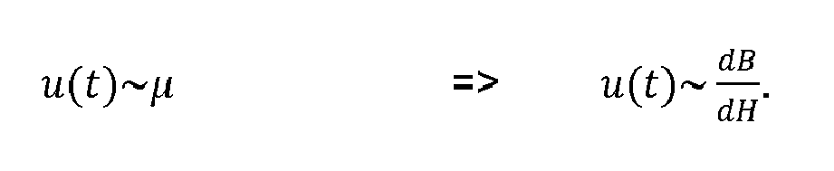
Da die in dem Schwingkreis 6 eingebrachte Stromstärke vorgegeben ist, ergibt sich eine feste Änderung der magnetischen Feldstärke ΔH wie folgt (Formel 4): 
Folglich wird erfindungsgemäß eine Änderung der magnetischen Flussdichte ΔB in Folge einer vorgegebenen Änderung der magnetischen Feldstärke ΔH gemessen. So rufen Änderungen des äußeren Magnetfelds 10 durch einen lediglich elektrisch leitenden bzw. ferromagnetischen ersten Bedienabschnitt 21 des Bedienwerkzeugs 20 Wirbelströme hervor. Diese Wirbelströme erzeugen ihrerseits ein Magnetfeld im Bedienabschnitt 21, das gemäß der Lenzschen Regel der Änderung des magnetischen Feldes 10 entgegenwirkt. Als Resultat wird die Änderung der Magnetischen Flussdichte ΔB, welche durch die Änderung der magnetischen Feldstärke ΔH in der Spule 8 hervorgerufen wird, reduziert bzw. gedämpft. Diese Dämpfung ist durch den reduzierten Spannungsabfall über die Spule 8 messbar.Consequently, according to the invention, a change in the magnetic flux density ΔB is measured as a result of a predetermined change in the magnetic field strength ΔH. Thus, changes in the external
Im Falle der Verwendung eines permanent- und/oder elektromagnetischen weiteren Bedienabschnitts 22 des Bedienwerkzeugs 20 überlagert sich eine durch den weiteren Bedienabschnitt 22 hervorgerufene konstante magnetische Feldstärke Hmagnet mit einer durch die Spule hervorgerufene Änderung der magnetischen Feldstärke ΔHSpule, da die Permeabilität µ des Ferritkerns nicht konstant ist, sondern mit zunehmender Feldstärke abnimmt. Eine gleiche Änderung der Feldstärke ruft dadurch deutlich geringere Änderungen der magnetischen Flussdichte ΔB und damit einen geringeren Spannungsabfall über die Spule hervor. Aus
In
Im Rahmen des Erfindungsgedankens sind Abweichungen von den oben beschriebenen Ausführungsformen möglich. So kann eine erfindungsgemäße Anordnung 1, 1' erfindungsgemäße Sensorvorrichtung 2, 2' und Bedienwerkzeuge 20 in beliebiger Anzahl, Form und Ausgestaltung umfassen. Die Sensorvorrichtung 2, 2' kann Gehäuse 3, Schaltungen 4, Leiterplatten 5, Schwingkreise 6, Auswerteeinheiten 7, Spulen 8, Spulenkerne 9, elektromagnetische Felder 10, Signalgeber 11, Leiter 12, Anzeigeelemente 13 und Schaltzonen 14 in beliebiger Anzahl, Ausgestaltung und Verschaltung umfassen, um die jeweiligen Anforderungen zu erfüllen. Entsprechend kann ein erfindungsgemäßes Bedienwerkzeug 20 Bedienabschnitte 21 und weitere Bedienabschnitte 22 in beliebiger Form und Anzahl aufweisen, um damit eine erfindungsgemäße Sensorvorrichtung 2, 2' bedienen zu können, die selbstverständlich auch mit anderen dazu geeigneten Werkzeugen bedient werden kann.Within the scope of the inventive concept, deviations from the embodiments described above are possible. Thus, an
Claims (15)
Priority Applications (1)
| Application Number | Priority Date | Filing Date | Title |
|---|---|---|---|
| EP14190723.8A EP3015826B1 (en) | 2014-10-28 | 2014-10-28 | Sensor device, operating tool and method for operating the same |
Applications Claiming Priority (1)
| Application Number | Priority Date | Filing Date | Title |
|---|---|---|---|
| EP14190723.8A EP3015826B1 (en) | 2014-10-28 | 2014-10-28 | Sensor device, operating tool and method for operating the same |
Publications (2)
| Publication Number | Publication Date |
|---|---|
| EP3015826A1 true EP3015826A1 (en) | 2016-05-04 |
| EP3015826B1 EP3015826B1 (en) | 2017-09-20 |
Family
ID=51844537
Family Applications (1)
| Application Number | Title | Priority Date | Filing Date |
|---|---|---|---|
| EP14190723.8A Active EP3015826B1 (en) | 2014-10-28 | 2014-10-28 | Sensor device, operating tool and method for operating the same |
Country Status (1)
| Country | Link |
|---|---|
| EP (1) | EP3015826B1 (en) |
Citations (2)
| Publication number | Priority date | Publication date | Assignee | Title |
|---|---|---|---|---|
| DE1175327B (en) * | 1961-10-28 | 1964-08-06 | Heinz Hoetten | Electric proximity switch using an oscillating circuit |
| DE102006032226A1 (en) * | 2006-07-07 | 2008-01-17 | Pilz Gmbh & Co. Kg | Method and device for safe distance monitoring |
Family Cites Families (2)
| Publication number | Priority date | Publication date | Assignee | Title |
|---|---|---|---|---|
| DE102007054604A1 (en) * | 2007-11-15 | 2009-05-28 | Siemens Medical Instruments Pte. Ltd. | Hearing device, particularly portable hearing aid such as headset or headphone, has housing, and input element, which is rotationally stored in or at housing for manual signal input |
| DE102008010864A1 (en) * | 2008-02-25 | 2009-08-27 | Endress + Hauser Process Solutions Ag | Method for operating a field device |
-
2014
- 2014-10-28 EP EP14190723.8A patent/EP3015826B1/en active Active
Patent Citations (2)
| Publication number | Priority date | Publication date | Assignee | Title |
|---|---|---|---|---|
| DE1175327B (en) * | 1961-10-28 | 1964-08-06 | Heinz Hoetten | Electric proximity switch using an oscillating circuit |
| DE102006032226A1 (en) * | 2006-07-07 | 2008-01-17 | Pilz Gmbh & Co. Kg | Method and device for safe distance monitoring |
Also Published As
| Publication number | Publication date |
|---|---|
| EP3015826B1 (en) | 2017-09-20 |
Similar Documents
| Publication | Publication Date | Title |
|---|---|---|
| EP2527795B1 (en) | Position sensor, actuator-sensor device and method for inductive detection of a position | |
| EP1797463B1 (en) | Device for locating metallic objects and method for adjusting such a device | |
| WO2018177580A1 (en) | Door handle assembly for a motor vehicle having a capacitive sensor and near-field communication | |
| DE102010007620A1 (en) | Proximity sensor | |
| EP2149784B1 (en) | Magnetic path sensor system | |
| DE102013200698A1 (en) | Coil arrangement with two coils | |
| EP3417245B1 (en) | Sensor | |
| WO2019121988A1 (en) | Electronic device comprising a sensor | |
| DE102004053551A1 (en) | Detector of mobile, or movable part, electrically and/or magnetically conductive, incorporates two electric circuits and control and/or regulating device, with specified components of both electric circuits | |
| DE102006061771B4 (en) | Magnetic displacement sensor with linear characteristic of the output signal | |
| DE10352351B4 (en) | Influencing unit e.g. piston, positioning determining process for measuring linear motion of influencing unit, involves measuring impedance of coil/tuned circuit with which position of influencing unit can be determined | |
| EP3015826B1 (en) | Sensor device, operating tool and method for operating the same | |
| EP3417244B1 (en) | Sensor | |
| DE102012202825B4 (en) | Inductive proximity switch | |
| EP3607360A1 (en) | Device and method for detecting electrically conductive measurement objects in a substrate | |
| DE19809567C2 (en) | Hearing aid and method for suppressing magnetic interference fields | |
| DE102004032258A1 (en) | Inductive proximity sensor adjusts effect of metallic device on reference and sensor coils to provide same sensitivity for ferro and non-ferromagnetic materials | |
| WO2012100804A2 (en) | Metal detector | |
| WO2018220079A1 (en) | Inductive touch sensor and method for operating same | |
| DE102017210943A1 (en) | Method for calibrating an inductive position sensor and location sensor | |
| EP3141869A1 (en) | Phase-based position detection using termination blind resistors | |
| EP2184623A2 (en) | Sensor device for detecting an object and its movement in a measurement area of the sensor device |
Legal Events
| Date | Code | Title | Description |
|---|---|---|---|
| PUAI | Public reference made under article 153(3) epc to a published international application that has entered the european phase |
Free format text: ORIGINAL CODE: 0009012 |
|
| AK | Designated contracting states |
Kind code of ref document: A1 Designated state(s): AL AT BE BG CH CY CZ DE DK EE ES FI FR GB GR HR HU IE IS IT LI LT LU LV MC MK MT NL NO PL PT RO RS SE SI SK SM TR |
|
| AX | Request for extension of the european patent |
Extension state: BA ME |
|
| 17P | Request for examination filed |
Effective date: 20161103 |
|
| RBV | Designated contracting states (corrected) |
Designated state(s): AL AT BE BG CH CY CZ DE DK EE ES FI FR GB GR HR HU IE IS IT LI LT LU LV MC MK MT NL NO PL PT RO RS SE SI SK SM TR |
|
| 17Q | First examination report despatched |
Effective date: 20170130 |
|
| GRAP | Despatch of communication of intention to grant a patent |
Free format text: ORIGINAL CODE: EPIDOSNIGR1 |
|
| INTG | Intention to grant announced |
Effective date: 20170620 |
|
| GRAS | Grant fee paid |
Free format text: ORIGINAL CODE: EPIDOSNIGR3 |
|
| GRAA | (expected) grant |
Free format text: ORIGINAL CODE: 0009210 |
|
| AK | Designated contracting states |
Kind code of ref document: B1 Designated state(s): AL AT BE BG CH CY CZ DE DK EE ES FI FR GB GR HR HU IE IS IT LI LT LU LV MC MK MT NL NO PL PT RO RS SE SI SK SM TR |
|
| REG | Reference to a national code |
Ref country code: GB Ref legal event code: FG4D Free format text: NOT ENGLISH |
|
| REG | Reference to a national code |
Ref country code: CH Ref legal event code: EP |
|
| REG | Reference to a national code |
Ref country code: AT Ref legal event code: REF Ref document number: 930526 Country of ref document: AT Kind code of ref document: T Effective date: 20171015 |
|
| REG | Reference to a national code |
Ref country code: IE Ref legal event code: FG4D Free format text: LANGUAGE OF EP DOCUMENT: GERMAN |
|
| REG | Reference to a national code |
Ref country code: DE Ref legal event code: R096 Ref document number: 502014005509 Country of ref document: DE |
|
| REG | Reference to a national code |
Ref country code: FR Ref legal event code: PLFP Year of fee payment: 4 |
|
| REG | Reference to a national code |
Ref country code: NL Ref legal event code: MP Effective date: 20170920 |
|
| PG25 | Lapsed in a contracting state [announced via postgrant information from national office to epo] |
Ref country code: NO Free format text: LAPSE BECAUSE OF FAILURE TO SUBMIT A TRANSLATION OF THE DESCRIPTION OR TO PAY THE FEE WITHIN THE PRESCRIBED TIME-LIMIT Effective date: 20171220 Ref country code: HR Free format text: LAPSE BECAUSE OF FAILURE TO SUBMIT A TRANSLATION OF THE DESCRIPTION OR TO PAY THE FEE WITHIN THE PRESCRIBED TIME-LIMIT Effective date: 20170920 Ref country code: SE Free format text: LAPSE BECAUSE OF FAILURE TO SUBMIT A TRANSLATION OF THE DESCRIPTION OR TO PAY THE FEE WITHIN THE PRESCRIBED TIME-LIMIT Effective date: 20170920 Ref country code: LT Free format text: LAPSE BECAUSE OF FAILURE TO SUBMIT A TRANSLATION OF THE DESCRIPTION OR TO PAY THE FEE WITHIN THE PRESCRIBED TIME-LIMIT Effective date: 20170920 Ref country code: FI Free format text: LAPSE BECAUSE OF FAILURE TO SUBMIT A TRANSLATION OF THE DESCRIPTION OR TO PAY THE FEE WITHIN THE PRESCRIBED TIME-LIMIT Effective date: 20170920 |
|
| REG | Reference to a national code |
Ref country code: LT Ref legal event code: MG4D |
|
| PG25 | Lapsed in a contracting state [announced via postgrant information from national office to epo] |
Ref country code: GR Free format text: LAPSE BECAUSE OF FAILURE TO SUBMIT A TRANSLATION OF THE DESCRIPTION OR TO PAY THE FEE WITHIN THE PRESCRIBED TIME-LIMIT Effective date: 20171221 Ref country code: LV Free format text: LAPSE BECAUSE OF FAILURE TO SUBMIT A TRANSLATION OF THE DESCRIPTION OR TO PAY THE FEE WITHIN THE PRESCRIBED TIME-LIMIT Effective date: 20170920 Ref country code: RS Free format text: LAPSE BECAUSE OF FAILURE TO SUBMIT A TRANSLATION OF THE DESCRIPTION OR TO PAY THE FEE WITHIN THE PRESCRIBED TIME-LIMIT Effective date: 20170920 Ref country code: BG Free format text: LAPSE BECAUSE OF FAILURE TO SUBMIT A TRANSLATION OF THE DESCRIPTION OR TO PAY THE FEE WITHIN THE PRESCRIBED TIME-LIMIT Effective date: 20171220 |
|
| PG25 | Lapsed in a contracting state [announced via postgrant information from national office to epo] |
Ref country code: NL Free format text: LAPSE BECAUSE OF FAILURE TO SUBMIT A TRANSLATION OF THE DESCRIPTION OR TO PAY THE FEE WITHIN THE PRESCRIBED TIME-LIMIT Effective date: 20170920 |
|
| PG25 | Lapsed in a contracting state [announced via postgrant information from national office to epo] |
Ref country code: ES Free format text: LAPSE BECAUSE OF FAILURE TO SUBMIT A TRANSLATION OF THE DESCRIPTION OR TO PAY THE FEE WITHIN THE PRESCRIBED TIME-LIMIT Effective date: 20170920 Ref country code: PL Free format text: LAPSE BECAUSE OF FAILURE TO SUBMIT A TRANSLATION OF THE DESCRIPTION OR TO PAY THE FEE WITHIN THE PRESCRIBED TIME-LIMIT Effective date: 20170920 Ref country code: RO Free format text: LAPSE BECAUSE OF FAILURE TO SUBMIT A TRANSLATION OF THE DESCRIPTION OR TO PAY THE FEE WITHIN THE PRESCRIBED TIME-LIMIT Effective date: 20170920 Ref country code: CZ Free format text: LAPSE BECAUSE OF FAILURE TO SUBMIT A TRANSLATION OF THE DESCRIPTION OR TO PAY THE FEE WITHIN THE PRESCRIBED TIME-LIMIT Effective date: 20170920 |
|
| PG25 | Lapsed in a contracting state [announced via postgrant information from national office to epo] |
Ref country code: IS Free format text: LAPSE BECAUSE OF FAILURE TO SUBMIT A TRANSLATION OF THE DESCRIPTION OR TO PAY THE FEE WITHIN THE PRESCRIBED TIME-LIMIT Effective date: 20180120 Ref country code: SK Free format text: LAPSE BECAUSE OF FAILURE TO SUBMIT A TRANSLATION OF THE DESCRIPTION OR TO PAY THE FEE WITHIN THE PRESCRIBED TIME-LIMIT Effective date: 20170920 Ref country code: EE Free format text: LAPSE BECAUSE OF FAILURE TO SUBMIT A TRANSLATION OF THE DESCRIPTION OR TO PAY THE FEE WITHIN THE PRESCRIBED TIME-LIMIT Effective date: 20170920 Ref country code: IT Free format text: LAPSE BECAUSE OF FAILURE TO SUBMIT A TRANSLATION OF THE DESCRIPTION OR TO PAY THE FEE WITHIN THE PRESCRIBED TIME-LIMIT Effective date: 20170920 Ref country code: SM Free format text: LAPSE BECAUSE OF FAILURE TO SUBMIT A TRANSLATION OF THE DESCRIPTION OR TO PAY THE FEE WITHIN THE PRESCRIBED TIME-LIMIT Effective date: 20170920 |
|
| REG | Reference to a national code |
Ref country code: DE Ref legal event code: R097 Ref document number: 502014005509 Country of ref document: DE |
|
| PG25 | Lapsed in a contracting state [announced via postgrant information from national office to epo] |
Ref country code: MC Free format text: LAPSE BECAUSE OF FAILURE TO SUBMIT A TRANSLATION OF THE DESCRIPTION OR TO PAY THE FEE WITHIN THE PRESCRIBED TIME-LIMIT Effective date: 20170920 |
|
| REG | Reference to a national code |
Ref country code: IE Ref legal event code: MM4A |
|
| PLBE | No opposition filed within time limit |
Free format text: ORIGINAL CODE: 0009261 |
|
| STAA | Information on the status of an ep patent application or granted ep patent |
Free format text: STATUS: NO OPPOSITION FILED WITHIN TIME LIMIT |
|
| PG25 | Lapsed in a contracting state [announced via postgrant information from national office to epo] |
Ref country code: LU Free format text: LAPSE BECAUSE OF NON-PAYMENT OF DUE FEES Effective date: 20171028 Ref country code: DK Free format text: LAPSE BECAUSE OF FAILURE TO SUBMIT A TRANSLATION OF THE DESCRIPTION OR TO PAY THE FEE WITHIN THE PRESCRIBED TIME-LIMIT Effective date: 20170920 |
|
| REG | Reference to a national code |
Ref country code: BE Ref legal event code: MM Effective date: 20171031 |
|
| 26N | No opposition filed |
Effective date: 20180621 |
|
| PG25 | Lapsed in a contracting state [announced via postgrant information from national office to epo] |
Ref country code: BE Free format text: LAPSE BECAUSE OF NON-PAYMENT OF DUE FEES Effective date: 20171031 |
|
| PG25 | Lapsed in a contracting state [announced via postgrant information from national office to epo] |
Ref country code: MT Free format text: LAPSE BECAUSE OF FAILURE TO SUBMIT A TRANSLATION OF THE DESCRIPTION OR TO PAY THE FEE WITHIN THE PRESCRIBED TIME-LIMIT Effective date: 20170920 |
|
| REG | Reference to a national code |
Ref country code: FR Ref legal event code: PLFP Year of fee payment: 5 |
|
| PG25 | Lapsed in a contracting state [announced via postgrant information from national office to epo] |
Ref country code: IE Free format text: LAPSE BECAUSE OF NON-PAYMENT OF DUE FEES Effective date: 20171028 |
|
| PG25 | Lapsed in a contracting state [announced via postgrant information from national office to epo] |
Ref country code: SI Free format text: LAPSE BECAUSE OF FAILURE TO SUBMIT A TRANSLATION OF THE DESCRIPTION OR TO PAY THE FEE WITHIN THE PRESCRIBED TIME-LIMIT Effective date: 20170920 |
|
| PGFP | Annual fee paid to national office [announced via postgrant information from national office to epo] |
Ref country code: GB Payment date: 20181218 Year of fee payment: 12 |
|
| PG25 | Lapsed in a contracting state [announced via postgrant information from national office to epo] |
Ref country code: HU Free format text: LAPSE BECAUSE OF FAILURE TO SUBMIT A TRANSLATION OF THE DESCRIPTION OR TO PAY THE FEE WITHIN THE PRESCRIBED TIME-LIMIT; INVALID AB INITIO Effective date: 20141028 |
|
| PG25 | Lapsed in a contracting state [announced via postgrant information from national office to epo] |
Ref country code: CY Free format text: LAPSE BECAUSE OF FAILURE TO SUBMIT A TRANSLATION OF THE DESCRIPTION OR TO PAY THE FEE WITHIN THE PRESCRIBED TIME-LIMIT Effective date: 20170920 |
|
| PG25 | Lapsed in a contracting state [announced via postgrant information from national office to epo] |
Ref country code: MK Free format text: LAPSE BECAUSE OF FAILURE TO SUBMIT A TRANSLATION OF THE DESCRIPTION OR TO PAY THE FEE WITHIN THE PRESCRIBED TIME-LIMIT Effective date: 20170920 |
|
| PG25 | Lapsed in a contracting state [announced via postgrant information from national office to epo] |
Ref country code: TR Free format text: LAPSE BECAUSE OF FAILURE TO SUBMIT A TRANSLATION OF THE DESCRIPTION OR TO PAY THE FEE WITHIN THE PRESCRIBED TIME-LIMIT Effective date: 20170920 |
|
| PGFP | Annual fee paid to national office [announced via postgrant information from national office to epo] |
Ref country code: CH Payment date: 20191023 Year of fee payment: 6 |
|
| PG25 | Lapsed in a contracting state [announced via postgrant information from national office to epo] |
Ref country code: PT Free format text: LAPSE BECAUSE OF FAILURE TO SUBMIT A TRANSLATION OF THE DESCRIPTION OR TO PAY THE FEE WITHIN THE PRESCRIBED TIME-LIMIT Effective date: 20170920 |
|
| PG25 | Lapsed in a contracting state [announced via postgrant information from national office to epo] |
Ref country code: AL Free format text: LAPSE BECAUSE OF FAILURE TO SUBMIT A TRANSLATION OF THE DESCRIPTION OR TO PAY THE FEE WITHIN THE PRESCRIBED TIME-LIMIT Effective date: 20170920 |
|
| GBPC | Gb: european patent ceased through non-payment of renewal fee |
Effective date: 20191028 |
|
| PG25 | Lapsed in a contracting state [announced via postgrant information from national office to epo] |
Ref country code: GB Free format text: LAPSE BECAUSE OF NON-PAYMENT OF DUE FEES Effective date: 20191028 |
|
| REG | Reference to a national code |
Ref country code: AT Ref legal event code: MM01 Ref document number: 930526 Country of ref document: AT Kind code of ref document: T Effective date: 20191028 |
|
| PG25 | Lapsed in a contracting state [announced via postgrant information from national office to epo] |
Ref country code: AT Free format text: LAPSE BECAUSE OF NON-PAYMENT OF DUE FEES Effective date: 20191028 |
|
| REG | Reference to a national code |
Ref country code: CH Ref legal event code: PL |
|
| PG25 | Lapsed in a contracting state [announced via postgrant information from national office to epo] |
Ref country code: LI Free format text: LAPSE BECAUSE OF NON-PAYMENT OF DUE FEES Effective date: 20201031 Ref country code: CH Free format text: LAPSE BECAUSE OF NON-PAYMENT OF DUE FEES Effective date: 20201031 |
|
| PGFP | Annual fee paid to national office [announced via postgrant information from national office to epo] |
Ref country code: FR Payment date: 20231023 Year of fee payment: 10 Ref country code: DE Payment date: 20231018 Year of fee payment: 10 |