EP2149784B1 - Magnetic path sensor system - Google Patents
Magnetic path sensor system Download PDFInfo
- Publication number
- EP2149784B1 EP2149784B1 EP20080013718 EP08013718A EP2149784B1 EP 2149784 B1 EP2149784 B1 EP 2149784B1 EP 20080013718 EP20080013718 EP 20080013718 EP 08013718 A EP08013718 A EP 08013718A EP 2149784 B1 EP2149784 B1 EP 2149784B1
- Authority
- EP
- European Patent Office
- Prior art keywords
- core
- sensor system
- magnetic
- magnet
- displacement sensor
- Prior art date
- Legal status (The legal status is an assumption and is not a legal conclusion. Google has not performed a legal analysis and makes no representation as to the accuracy of the status listed.)
- Expired - Fee Related
Links
- 230000005291 magnetic effect Effects 0.000 title claims description 35
- 238000006073 displacement reaction Methods 0.000 claims description 27
- 239000004020 conductor Substances 0.000 claims description 23
- 238000011156 evaluation Methods 0.000 claims description 9
- 238000009413 insulation Methods 0.000 claims 2
- BGPVFRJUHWVFKM-UHFFFAOYSA-N N1=C2C=CC=CC2=[N+]([O-])C1(CC1)CCC21N=C1C=CC=CC1=[N+]2[O-] Chemical compound N1=C2C=CC=CC2=[N+]([O-])C1(CC1)CCC21N=C1C=CC=CC1=[N+]2[O-] BGPVFRJUHWVFKM-UHFFFAOYSA-N 0.000 description 13
- 238000005516 engineering process Methods 0.000 description 8
- 230000004907 flux Effects 0.000 description 7
- 230000033001 locomotion Effects 0.000 description 7
- 238000004804 winding Methods 0.000 description 6
- 238000004519 manufacturing process Methods 0.000 description 5
- 239000000758 substrate Substances 0.000 description 5
- 238000001746 injection moulding Methods 0.000 description 4
- 238000010586 diagram Methods 0.000 description 3
- 230000006698 induction Effects 0.000 description 3
- 238000010276 construction Methods 0.000 description 2
- 238000013461 design Methods 0.000 description 2
- 238000011161 development Methods 0.000 description 2
- 230000018109 developmental process Effects 0.000 description 2
- 230000005294 ferromagnetic effect Effects 0.000 description 2
- 230000036039 immunity Effects 0.000 description 2
- 239000000696 magnetic material Substances 0.000 description 2
- 238000005259 measurement Methods 0.000 description 2
- 238000000034 method Methods 0.000 description 2
- XAGFODPZIPBFFR-UHFFFAOYSA-N aluminium Chemical compound [Al] XAGFODPZIPBFFR-UHFFFAOYSA-N 0.000 description 1
- 229910052782 aluminium Inorganic materials 0.000 description 1
- 230000015572 biosynthetic process Effects 0.000 description 1
- 238000007796 conventional method Methods 0.000 description 1
- 238000009795 derivation Methods 0.000 description 1
- 238000001514 detection method Methods 0.000 description 1
- 230000005284 excitation Effects 0.000 description 1
- 239000003302 ferromagnetic material Substances 0.000 description 1
- 238000001465 metallisation Methods 0.000 description 1
- 230000035699 permeability Effects 0.000 description 1
- 238000005476 soldering Methods 0.000 description 1
- 238000003466 welding Methods 0.000 description 1
Images


Classifications
-
- G—PHYSICS
- G01—MEASURING; TESTING
- G01D—MEASURING NOT SPECIALLY ADAPTED FOR A SPECIFIC VARIABLE; ARRANGEMENTS FOR MEASURING TWO OR MORE VARIABLES NOT COVERED IN A SINGLE OTHER SUBCLASS; TARIFF METERING APPARATUS; MEASURING OR TESTING NOT OTHERWISE PROVIDED FOR
- G01D5/00—Mechanical means for transferring the output of a sensing member; Means for converting the output of a sensing member to another variable where the form or nature of the sensing member does not constrain the means for converting; Transducers not specially adapted for a specific variable
- G01D5/12—Mechanical means for transferring the output of a sensing member; Means for converting the output of a sensing member to another variable where the form or nature of the sensing member does not constrain the means for converting; Transducers not specially adapted for a specific variable using electric or magnetic means
- G01D5/14—Mechanical means for transferring the output of a sensing member; Means for converting the output of a sensing member to another variable where the form or nature of the sensing member does not constrain the means for converting; Transducers not specially adapted for a specific variable using electric or magnetic means influencing the magnitude of a current or voltage
- G01D5/20—Mechanical means for transferring the output of a sensing member; Means for converting the output of a sensing member to another variable where the form or nature of the sensing member does not constrain the means for converting; Transducers not specially adapted for a specific variable using electric or magnetic means influencing the magnitude of a current or voltage by varying inductance, e.g. by a movable armature
- G01D5/204—Mechanical means for transferring the output of a sensing member; Means for converting the output of a sensing member to another variable where the form or nature of the sensing member does not constrain the means for converting; Transducers not specially adapted for a specific variable using electric or magnetic means influencing the magnitude of a current or voltage by varying inductance, e.g. by a movable armature by influencing the mutual induction between two or more coils
- G01D5/2046—Mechanical means for transferring the output of a sensing member; Means for converting the output of a sensing member to another variable where the form or nature of the sensing member does not constrain the means for converting; Transducers not specially adapted for a specific variable using electric or magnetic means influencing the magnitude of a current or voltage by varying inductance, e.g. by a movable armature by influencing the mutual induction between two or more coils by a movable ferromagnetic element, e.g. a core
-
- G—PHYSICS
- G01—MEASURING; TESTING
- G01D—MEASURING NOT SPECIALLY ADAPTED FOR A SPECIFIC VARIABLE; ARRANGEMENTS FOR MEASURING TWO OR MORE VARIABLES NOT COVERED IN A SINGLE OTHER SUBCLASS; TARIFF METERING APPARATUS; MEASURING OR TESTING NOT OTHERWISE PROVIDED FOR
- G01D5/00—Mechanical means for transferring the output of a sensing member; Means for converting the output of a sensing member to another variable where the form or nature of the sensing member does not constrain the means for converting; Transducers not specially adapted for a specific variable
- G01D5/12—Mechanical means for transferring the output of a sensing member; Means for converting the output of a sensing member to another variable where the form or nature of the sensing member does not constrain the means for converting; Transducers not specially adapted for a specific variable using electric or magnetic means
- G01D5/14—Mechanical means for transferring the output of a sensing member; Means for converting the output of a sensing member to another variable where the form or nature of the sensing member does not constrain the means for converting; Transducers not specially adapted for a specific variable using electric or magnetic means influencing the magnitude of a current or voltage
- G01D5/20—Mechanical means for transferring the output of a sensing member; Means for converting the output of a sensing member to another variable where the form or nature of the sensing member does not constrain the means for converting; Transducers not specially adapted for a specific variable using electric or magnetic means influencing the magnitude of a current or voltage by varying inductance, e.g. by a movable armature
- G01D5/2006—Mechanical means for transferring the output of a sensing member; Means for converting the output of a sensing member to another variable where the form or nature of the sensing member does not constrain the means for converting; Transducers not specially adapted for a specific variable using electric or magnetic means influencing the magnitude of a current or voltage by varying inductance, e.g. by a movable armature by influencing the self-induction of one or more coils
- G01D5/2033—Mechanical means for transferring the output of a sensing member; Means for converting the output of a sensing member to another variable where the form or nature of the sensing member does not constrain the means for converting; Transducers not specially adapted for a specific variable using electric or magnetic means influencing the magnitude of a current or voltage by varying inductance, e.g. by a movable armature by influencing the self-induction of one or more coils controlling the saturation of a magnetic circuit by means of a movable element, e.g. a magnet
-
- H—ELECTRICITY
- H01—ELECTRIC ELEMENTS
- H01F—MAGNETS; INDUCTANCES; TRANSFORMERS; SELECTION OF MATERIALS FOR THEIR MAGNETIC PROPERTIES
- H01F17/00—Fixed inductances of the signal type
- H01F17/04—Fixed inductances of the signal type with magnetic core
- H01F17/06—Fixed inductances of the signal type with magnetic core with core substantially closed in itself, e.g. toroid
- H01F17/062—Toroidal core with turns of coil around it
-
- H—ELECTRICITY
- H01—ELECTRIC ELEMENTS
- H01F—MAGNETS; INDUCTANCES; TRANSFORMERS; SELECTION OF MATERIALS FOR THEIR MAGNETIC PROPERTIES
- H01F3/00—Cores, Yokes, or armatures
- H01F3/10—Composite arrangements of magnetic circuits
- H01F2003/103—Magnetic circuits with permanent magnets
-
- H—ELECTRICITY
- H01—ELECTRIC ELEMENTS
- H01F—MAGNETS; INDUCTANCES; TRANSFORMERS; SELECTION OF MATERIALS FOR THEIR MAGNETIC PROPERTIES
- H01F21/00—Variable inductances or transformers of the signal type
- H01F21/02—Variable inductances or transformers of the signal type continuously variable, e.g. variometers
- H01F21/06—Variable inductances or transformers of the signal type continuously variable, e.g. variometers by movement of core or part of core relative to the windings as a whole
- H01F21/065—Measures for obtaining a desired relation between the position of the core and the inductance
Landscapes
- Physics & Mathematics (AREA)
- General Physics & Mathematics (AREA)
- Transmission And Conversion Of Sensor Element Output (AREA)
- Measurement Of Length, Angles, Or The Like Using Electric Or Magnetic Means (AREA)
Description
Die Erfindung betrifft ein magnetisches Wegsensorsystem.The invention relates to a magnetic displacement sensor system.
Derartige Sensorsysteme sind beispielsweise aus
Aus
Die Aufgabe der Erfindung ist es, ein magnetisches Wegsensorsystem zu schaffen, das zur berührungslosen Positionsbestimmung eines Bauteils durch eine Wand geeignet ist, wobei es gegenüber den bekannten Sensoreinrichtungen dieser Art verbesserte magnetische Eigenschaften und damit einhergehend eine verbesserte Messgenauigkeit und Störfestigkeit aufweist.The object of the invention is to provide a magnetic position sensor system which is suitable for non-contact position determination of a component by a wall, wherein it has improved magnetic properties compared to the known sensor devices of this type and, consequently, improved measurement accuracy and immunity to interference.
Gelöst wird diese Aufgabe durch ein magnetisches Wegsensorsystem mit den im Anspruch 1 angegebenen Merkmalen. Bevorzugte Weiterbildungen dieses Wegsensorsystems ergeben sich aus den Unteransprüchen, der nachfolgenden Beschreibung sowie den Zeichnungen.This object is achieved by a magnetic displacement sensor system with the features specified in claim 1. Preferred developments of this sensor system result from the subclaims, the following description and the drawings.
Das erfindungsgemäße magnetische Wegsensorsystem weist zumindest einen Magneten, vorzugsweise einen Permanentmagneten, und zumindest einen Sensor auf. Der Magnet und der Sensor sind relativ zueinander beweglich angeordnet. Bevorzugt ist der Magnet bewegbar und der Sensor feststehend angeordnet. D.h., über den Sensor kann eine Positionsänderung des Magneten erfasst werden. Der Sensor weist einen weichmagnetischen Kern auf, der eine innere Freifläche umschließt. Hierzu weist der Kern zwei zueinander parallel ausgerichtete lineare Kernabschnitte auf, die an ihren axialen Enden jeweils mit einem sich quer oder bogenförmig anschließenden Kernabschnitten verbunden sind.The magnetic displacement sensor system according to the invention has at least one magnet, preferably a permanent magnet, and at least one sensor. The magnet and the sensor are arranged movable relative to each other. Preferably, the magnet is movable and the sensor is fixed. That is, via the sensor, a change in position of the magnet can be detected. The sensor has a soft-magnetic core, which encloses an inner free surface. For this purpose, the core has two mutually parallel aligned linear core sections, which are connected at their axial ends in each case with a transversely or arcuately adjoining core sections.
Auf dem Kern sind zwei Primärspulen und zwei Sekundärspulen angeordnet. Beide Primärspulen bilden die Messstrecke des Sensors und werden mit einer Wechselspannung beaufschlagt. In diesem Zusammenhang ist unter einer Wechselspannung jede sich zeitlich ändernde Spannung zu verstehen, der Begriff Wechselspannung ist also im Sinne der Erfindung nicht auf eine sich sinusförmig ändernde Spannung beschränkt. Zusammen bilden die Primärspulen und die Sekundärspulen einen Messtransformator.On the core, two primary coils and two secondary coils are arranged. Both primary coils form the measuring path of the sensor and are supplied with an alternating voltage. In this context, an alternating voltage is to be understood as meaning any time-varying voltage, that is to say that the term alternating voltage is not limited to a sinusoidally changing voltage within the meaning of the invention. Together, the primary coils and the secondary coils form a measuring transformer.
Erfindungsgemäß ist der Magnet außerhalb der von dem Kern aufgespannten Fläche, insbesondere außerhalb der von dem Kern umschlossenen Freifläche, angeordnet und zur Erzeugung einer magnetischen Sättigung in dem Kern ausgebildet, wobei der Magnet parallel zu dem Kernabschnitt bewegbar ist, auf dem eine Primärspule angeordnet ist. Dementsprechend verliert der die Primärspule tragende Kernabschnitt durch die von dem Magneten verursachte Sättigung auf Höhe der Position des Magneten seine magnetische Leitfähigkeit. Insofern weist der Kern an dieser Stelle die gleiche Permeabilität wie Luft auf, bildet also einen virtuellen Luftspalt, der die Primärspule in zwei Teilspulen aufteilt.According to the invention, the magnet is arranged outside of the area spanned by the core, in particular outside the free space enclosed by the core, and designed to generate a magnetic saturation in the core, the magnet being movable parallel to the core portion on which a primary coil is arranged. Accordingly, the core portion carrying the primary coil loses its magnetic conductivity due to the saturation caused by the magnet at the position of the magnet. In this respect, the core at this point has the same permeability as air, thus forming a virtual air gap, which divides the primary coil into two sub-coils.
Infolge der Anordnung des Magneten außerhalb der von dem Kern umschlossenen Freifläche, ist das erfindungsgemäße Wegsensorsystem dazu geeignet, Verfahrwege eines in einem Gehäuse angeordneten Bauteils, das in dem Gehäuse mit einem Magneten bewegungsgekoppelt ist, mit einem außerhalb des Gehäuses angeordneten Sensor zu erfassen. Da der erfindungsgemäß verwendete Kern einen geschlossenen Magnetkreis bildet, hat er bezüglich seiner magnetischen Eigenschaften gegenüber den in den bekannten Wegsensorsystemen bislang verwendeten stabförmigen Kernen erhebliche Vorteile. Hierzu zählen vor allem eine größere Störunempfindlichkeit und eine geringere Störausstrahlung des Kerns. Während an stabförmigen Kernen aufgrund der Streuung an den freien Enden des Kerns hohe magnetische Verluste entstehen, die sich insbesondere bei der Anwesenheit von ferromagnetischen Bauteilen in der Nähe des Sensors durch Ableitung des magnetischen Flusses in diese Bauteile als Messfehler äußern, sind die Streuverluste bei dem erfindungsgemäß verwendeten Kern deutlich geringer. Der magnetische Fluss durch die Sekundärspulen ist bei gleicher Erregerleistung deutlich höher, da der Kern keine freien Kernenden aufweist, an denen eine Streuung und somit Verluste auftreten können. So weist der erfindungsgemäße Sensor einen höheren Wirkungsgrad auf. Gleichzeitig kann ein erheblich besseres lineares Verhalten über die Messstrecke bis in die äußeren Endbereiche der Messstrecke erzielt werden. Während Sensoren mit den bislang üblichen stabförmigen Kernen eine hohe Anfälligkeit gegenüber magnetischen Fremdfeldern aufweisen, ist diese Anfälligkeit aufgrund der Kernausgestaltung des erfindungsgemäßen Sensors erheblich verringert. In der Nähe des Sensors angeordnete ferromagnetische Bauteile haben insofern nur geringe Auswirkungen auf den Sensor. Schließlich weist der Sensor wegen des erfindungsgemäß verwendeten Kerns auch eine verbesserte elektromagnetische Verträglichkeit gegenüber anderen elektronischen Bauteilen oder Geräten auf, da die Emission magnetischer Störfelder auf diese Bauteile bzw. Geräte ebenfalls wegen des geschlossenen Magnetkreises des Kerns weitestgehend ausbleibt.As a result of the arrangement of the magnet outside the free space enclosed by the core, the displacement sensor system according to the invention is suitable for detecting travel paths of a component arranged in a housing, which is motion-coupled in the housing with a magnet, with a sensor arranged outside the housing. Since the core used in the invention forms a closed magnetic circuit, it has considerable advantages in terms of its magnetic properties compared to the rod-shaped cores used in the known displacement sensor systems. These include above all a greater immunity to interference and a lower noise emission of the core. While on rod-shaped cores due to the scattering at the free ends of the core high magnetic losses arise, which manifest themselves as a measurement error in particular in the presence of ferromagnetic components in the vicinity of the sensor by derivation of the magnetic flux in these components, the scattering losses are significantly lower in the core used in the invention. The magnetic flux through the secondary coils is significantly higher for the same excitation power, since the core has no free core ends, where a scattering and thus losses can occur. Thus, the sensor according to the invention has a higher efficiency. At the same time, significantly better linear behavior can be achieved over the measuring section up to the outer end regions of the measuring section. While sensors with the hitherto usual rod-shaped cores have a high susceptibility to magnetic foreign fields, this susceptibility is considerably reduced due to the core configuration of the sensor according to the invention. In the vicinity of the sensor arranged ferromagnetic components have so far only a small impact on the sensor. Finally, because of the core used according to the invention, the sensor also has an improved electromagnetic compatibility with respect to other electronic components or devices, since the emission of magnetic interference fields to these components or devices also largely fails because of the closed magnetic circuit of the core.
Vorteilhaft kann der Kern einen im Wesentlichen rechteckigen Rahmen bilden. Der Kern kann also zwei parallel zueinander ausgerichtete gerade Kernabschnitte aufweisen, die an ihren axialen Enden jeweils mittels eines ebenfalls geraden Kernabschnitts verbunden sind. Hierbei sind auf den parallel zueinander ausgerichteten Kernabschnitten lediglich die Primärspulen angeordnet und auf den an diesen Kernabschnitten quer, insbesondere orthogonal anschließenden Kernabschnitten die Sekundärspulen angeordnet. Hierdurch kann der Sensor des erfindungsgemäßen Wegsensorsystems in Richtung der Messtrecke eine deutliche kompaktere Baugröße aufweisen.Advantageously, the core may form a substantially rectangular frame. The core can thus have two straight core sections oriented parallel to one another, which are each connected at their axial ends by means of a likewise straight core section. In this case, only the primary coils are arranged on the core sections oriented parallel to one another and the secondary coils are arranged on the core sections which are transverse, in particular orthogonal, at these core sections. As a result, the sensor of the displacement sensor system according to the invention in the direction of the measuring section have a clearer compact size.
Bei einer Ausgestaltung des Kerns, bei der der Kern zwei zueinander parallel ausgerichtete lineare Kernabschnitte aufweist, die an ihren axialen Enden jeweils mittels eines bogenförmigen bzw. ringsegmentförmigen Kernabschnitts miteinander verbunden sind, sind die Primärspulen auf den linearen Kernabschnitten angeordnet, während die Sekundärspulen jeweils auf den ringsegmentförmigen Kernabschnitten angeordnet sind. Dies ist insbesondere dann vorteilhaft, wenn der Sensor im Bereich der Messstrecke, also im Bereich der beiden linearen Kernabschnitte quer zur Längsausdehnung dieser beiden Kernabschnitte besonders schmal ausgebildet sein soll. In diesem Fall kann es zur Anordnung der Sekundärspulen auf den ringsegmentförmigen Kernabschnitten ggf. erforderlich sein, dass diese Kernabschnitte quer zur Längsausdehnung des Sensors eine Erweiterung bilden. Dabei müssen diese Kernabschnitte nicht kreisförmig ausgebildet sein, sondern können auch in anderer Form gekrümmt oder abgewinkelt sein.In an embodiment of the core, in which the core has two mutually parallel aligned linear core sections, which are connected to each other at their axial ends by means of an arcuate or ring-segment-shaped core portion, the primary coils are arranged on the linear core portions, while the secondary coils each on the Ring segment-shaped core sections are arranged. This is particularly advantageous if the sensor in the region of the measuring path, that is to say in the region of the two linear core sections, is to be particularly narrow transversely to the longitudinal extent of these two core sections. In this case, it may be necessary for the arrangement of the secondary coils on the ring-segment-shaped core sections that these core sections form an extension transverse to the longitudinal extent of the sensor. These core sections need not be circular, but may also be curved or angled in another form.
Bei dem erfindungsgemäßen magnetischen Wegsensorsystem sind die Primärspulen so verschaltet, dass beide Primärspulen einen im Kern umlaufenden Magnetfluss erzeugen, vorzugsweise sind die Primärspulen in Reihe geschaltet. Beide Primärspulen sind bevorzugt gleich lang, parallel zueinander angeordnet und weisen entlang der Messstrecke bevorzugt gleiche Anfangs- und Endpunkte auf, d.h. sie sind an zwei einander gegenüberliegendenIn the magnetic displacement sensor system according to the invention, the primary coils are connected so that both primary coils generate a magnetic flux circulating in the core, preferably the primary coils are connected in series. Both primary coils are preferably the same length, arranged parallel to one another and preferably have the same starting and ending points along the measuring path, ie they are at two opposing ones
Kernabschnitten zu einer Längs- bzw. Mittelachse des Kerns symmetrisch angeordnet. Der Magnet kann auch so zu den beiden Primärspulen angeordnet sein, dass beide Primärspulen einen Teil der Messstrecke bilden. Der Vorteil dieser Ausgestaltung liegt darin, dass der durch die beiden Primärspulen fließende Strom einen im Kern umlaufenden Magnetfluss erzeugt, der gegenüber dem Magnetfluss bei Verwendung einer Primärspule erhöht ist. Vorteilhaft führt dies zu einer Erhöhung des Signalpegels des Ausgangssignals der Spulenanordnung.Core portions arranged symmetrically to a longitudinal or central axis of the core. The magnet can also be arranged to the two primary coils so that both primary coils form part of the measuring path. The advantage of this embodiment is that the current flowing through the two primary coils generates a magnetic flux circulating in the core, which is increased in relation to the magnetic flux when using a primary coil. This advantageously leads to an increase in the signal level of the output signal of the coil arrangement.
Bei dem erfindungsgemäßen Sensoraufbau kann die Windungsanzahl der verwendeten Primär- und Sekundörspulen so gering sein, dass lediglich eine einlogige Wicklung dieser Spulen erforderlich ist. Dies ermöglicht es, Spulen zu verwenden, die nicht mittels Wickeltechnik hergestellt sind. So sieht eine vorteilhafte Weiterbildung der Erfindung vor, die Primärspule und/oder die Sekundärspule aus miteinander verbundenen planaren Leiterbahnen auszubilden. Bei dieser Ausbildung in Planartechnik ist der Kern zwischen planaren Leiterbahnen angeordnet, die seitlich des Kerns miteinander verbunden werden, um den Kern nach Art einer Spule vollständig zu umgeben. D.h., die planaren Leiterbahnen bilden Windungsabschnitte der Spule. Durch die elektrisch leitende Verbindung dieser Leiterbahnen bevorzugt seitlich des Kerns werden vollständige Windungen der Spule geschaffen. In diesem Zusammenhang ist es möglich, mit hoher Herstellungsgenauigkeit sowie mit hoher Herstellungsreproduzierbarkeit die Spulen nach Art einer Leiterplatte mit einem im Inneren angeordneten Kern auszubilden oder besonders vorteilhaft alle Sensorbestandteile wie z.B. den Kern, die Spulen und eine elektronische Auswerteeinrichtung mit den gängigen Verfahren der Platinenherstellung in ein und demselben Substrat unterzubringen oder darauf anzuordnen, was eine kostengünstige Massenfertigung des Sensors ermöglicht.In the case of the sensor structure according to the invention, the number of turns of the primary and secondary coils used can be so small that only a single-turn winding of these coils is required. This makes it possible to use coils that are not manufactured by means of winding technology. Thus, an advantageous development of the invention, the primary coil and / or the secondary coil of interconnected planar conductor tracks form. In this design in planar technology, the core is arranged between planar conductor tracks which are connected to one another laterally of the core in order to completely surround the core in the manner of a coil. That is, the planar conductor tracks form winding sections of the coil. Due to the electrically conductive connection of these interconnects preferably laterally of the core, complete turns of the coil are created. In this context, it is possible to design the coils in the manner of a printed circuit board with a core arranged inside with high manufacturing accuracy and with high manufacturing reproducibility or particularly advantageous all sensor components such as the core, the coils and an electronic evaluation device with the usual methods of board production in one or the same substrate to accommodate or arrange on it, which allows a cost-effective mass production of the sensor.
Eine kostengünstige Fertigung des Sensors kann auch dann erzielt werden, wenn, wie es weiter bevorzugt vorgesehen ist, der Kern eine Isolierummantelung aufweist. In diesem Fall kann beispielsweise mit den gängigen Verfahren der MID-Technologie auf den Kern zunächst eine Isolierummantelung aus Kunststoff aufgetragen werden, woraufhin dann die metallischen Leiterbahnen auf die Isolierummantelung aufgetragen werden und elektrisch leitende Verbindungen dieser Leiterbahnen geschaffen werden.A cost-effective production of the sensor can also be achieved if, as it is further preferred, the core has an insulating sheath. In this case, for example, with the conventional methods of MID technology on the core initially a Isolierummantelung plastic can be applied, whereupon the metallic interconnects are then applied to the Isolierummantelung and electrically conductive connections of these interconnects are created.
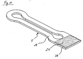
Weist der Kern eine Isolierummantelung auf, kann eine besonders kompakte Baugröße des Sensors erzielt werden, wenn vorteilhaft auf der Isolierummantelung eine Auswerteeinrichtung zu Ermittlung der Position des Magneten angeordnet wird. Hierbei ist die Auswerteeinrichtung bevorzugt neben dem Kern angeordnet.If the core has an insulating sheathing, a particularly compact size of the sensor can be achieved if an evaluation device for determining the position of the magnet is advantageously arranged on the insulating sheathing. In this case, the evaluation device is preferably arranged next to the core.
Vorteilhaft können die Leiterbahnen mittels Via-Bohrungen miteinander verbunden sein. Dies ist insbesondere dann zweckmäßig, wenn Teile der Spulen auf zwei entgegengesetzten Oberflächen einer Isolierummantelung ausgebildet sind. In diesem Fall ist die Leiterplatte bzw. die Isolierummantelung durchkontaktiert, d.h., die Leiterplatte weist metallisierte Bohrungen auf, die von einer Oberfläche der Leiterplatte zu der davon abgewandten Oberfläche verlaufen und eine Leitungsverbindung zwischen den einzelnen Leiterbahnabschnitten schaffen. So wird es möglich, die Leiterbahnen, welche Windungsabschnitte einer Spule auf den beiden entgegengesetzten Oberflächen der Leiterplatte bilden, beispielsweise durch Metallisierung der Bohrungen oder sonstige metallische Leiter, welche in die Bohrungen eingebracht werden, elektrisch leitend zu vollständigen Windungen der Spule zu verbinden.Advantageously, the conductor tracks can be connected to each other by means of via holes. This is particularly useful when parts of the coils are formed on two opposite surfaces of an insulating sheath. In this case, the circuit board or the Isolierummantelung is plated through, that is, the circuit board has metallized holes extending from a surface of the circuit board to the surface facing away therefrom and provide a line connection between the individual conductor track sections. Thus, it is possible, the conductor tracks, which form winding sections of a coil on the two opposite surfaces of the circuit board, for example, by metallization of the holes or other metallic conductors, which are introduced into the holes to connect electrically conductive to complete turns of the coil.
Wie bereits angemerkt worden ist, ist das erfindungsgemäße Wegsensorsystem auch zur berührungslosen Positionsbestimmung eines Bauteils durch eine Wand, z.B. durch ein Aluminiumgehäuse hindurch, geeignet. Insofern können der Magnet und der Sensor vorteilhaft an voneinander abgewandten Seiten einer Wand angeordnet sein. So ist es mit dem erfindungsgemäßen Wegsensorsystem möglich, den Verfahrweg eines in einem geschlossenen Gehäuse angeordneten Bauteils zu ermitteln, indem dieses Bauteil in dem Gehäuse mit dem Magneten bewegungsgekoppelt wird, wobei der Sensor außenseitig des Gehäuses angebracht wird.As has already been noted, the displacement sensor system according to the invention is also suitable for the non-contact position determination of a component through a wall, for example through an aluminum housing. In this respect, the magnet and the sensor can advantageously be arranged on opposite sides of a wall. Thus, it is possible with the displacement sensor system according to the invention to determine the travel of a arranged in a closed housing component by this component is motion-coupled in the housing with the magnet, wherein the sensor is mounted on the outside of the housing.
Nachfolgend wird die Erfindung beispielhaft anhand der, in den beigefügten Zeichnungsfiguren dargestellten Ausführungsbeispiele näher erläutert. In diesen zeigt:
- Fig. 1
- schematisch den Aufbau eines Weg- sensorsystems,
- Fig. 2
- ein schematisches Schaltbild eines Sensors des Wegsen- sorsystems nach
Fig. 1 . - Fig. 3
- schematisch den Aufbau des erfindungsgemäßen Weg- sensorsystems in einem Ausführungsbeispiel,
- Fig. 4
- ein schematisches Schaltbild eines Sensors, des Wegsen- sorsystems nach
Fig. 3 , - Fig. 5
- schematisch den Aufbau des erfindungsgemäßen Weg- sensorsystems in einem weiteren Ausführungsbeispiel,
- Fig. 6
- schematisch einen Sensor des Wegsensorsystems nach
Fig. 5 ohne eine Isolierummantelung des Kerns, - Fig. 7
- schematisch den Aufbau des erfindungsgemäßen Weg- sensorsystems in einem weiteren Ausführungsbeispiel,
- Fig. 8
- schematisch einen Sensor des Wegsensorsystems nach
Fig. 7 ohne eine Isolierummantelung des Kerns, - Fig. 9
- schematisch den Aufbau eines Weg- sensorsystems,
- Fig. 10
- schematisch einen Sensor des Wegsensorsystems nach
Fig. 9 ohne eine Isolierummantelung des Kerns und - Fig. 11
- schematisch einen Sensor mit einer darauf angeordneten Auswerteeinrichtung.
- Fig. 1
- schematically the structure of a position sensor system,
- Fig. 2
- a schematic diagram of a sensor of the sensor system according to
Fig. 1 , - Fig. 3
- 1 schematically the structure of the sensor system according to the invention in one exemplary embodiment,
- Fig. 4
- a schematic diagram of a sensor, the sensor system according to
Fig. 3 . - Fig. 5
- 2 shows a schematic of the construction of the sensor system according to the invention in a further exemplary embodiment,
- Fig. 6
- schematically a sensor of the displacement sensor system according to
Fig. 5 without an insulating sheath of the core, - Fig. 7
- 2 shows a schematic of the construction of the sensor system according to the invention in a further exemplary embodiment,
- Fig. 8
- schematically a sensor of the displacement sensor system according to
Fig. 7 without an insulating sheath of the core, - Fig. 9
- schematically the structure of a position sensor system,
- Fig. 10
- schematically a sensor of the displacement sensor system according to
Fig. 9 without an insulating sheath of the core and - Fig. 11
- schematically a sensor with an evaluation device arranged thereon.
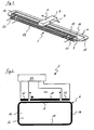
Um den Kernabschnitt 8 ist eine Primärspule 18 angeordnet. Außenseitig eines ersten Endes der Primärspule 18 ist eine Sekundärspule 20 und außenseitig eines zweiten Endes der Primärspule 18 ist eine zweite Sekundärspule 22 angeordnet. Die Spulen können herkömmlich gewickelt oder, wie unten beschrieben, in Planartechnik ausgebildet sein. Insbesondere dann, wenn die Spulen in herkömmlicher Weise auf den Kern 6 aufgewickelt werden, ist der Kern 6 bevorzugt zweiteilig ausgebildet. In diesem Fall besteht der Kern 6 aus einem ersten Teil, der von einem Kernabschnitt gebildet wird, und einem zweiten Teil, der von den übrigen Kernabschnitten gebildet wird. Beispielsweise können in den Kernabschnitten 12 und 14 Trennfugen vorgesehen sein, welche den Kern 6 in zwei U-förmige Kernteile teilen. Diese Ausgestaltung des Kerns 6 erleichtert das Aufwickeln der Primärspule 18 und der Sekundärspulen 20 und 22 auf dem Kern 6 oder ermöglicht es, die Primärspule 18 sowie die Sekundärspulen 20 und 22 vorgewickelt auf den Kern 6 aufzustecken. Anschließend werden die beiden Kernteile z.B. durch Löten oder Schweißen zu dem vollständigen Kern 6 verbunden. Wie aus dem Schaltbild der
Beabstandet von dem Kern 6 und beabstandet von der um den Kern 6 gewickelten Primärspule 18 ist der Magnet 4 parallel zu dem Kernabschnitt 8 in eine Richtung A und eine hierzu entgegengesetzte Richtung B bewegbar angeordnet. Hierbei sind die beiden Pole des Magneten 4 in Richtung der Längsausdehnung des Kernabschnitts 8 ausgerichtet. Der Magnet 4 ist mit einem nicht dargestellten Bauteil bewegungsgekoppelt, dessen Bewegungsweg bzw. Position ermittelt werden soll. Hierzu bildet die Primärspule 18 eine Messstrecke, wie nachfolgend ausführlich erläutert wird. Das mit dem Magneten 4 bewegungsgekoppelte Bauteil kann in einem geschlossenen Gehäuse angeordnet sein, wobei der Sensor 2 außerhalb dieses Gehäuses angeordnet ist. D.h. eine Wand liegt zwischen dem Magnet 4 und dem Sensor 2.Spaced apart from the
Das in den
Bei den in den
Bei dem in den
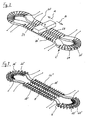
Auf zwei einander entgegengesetzten Oberflächen der Isolierummantelung 28 sind jeweils in dem Bereich, in dem zukünftig die Kernabschnitte 8', 10' 12' und 14' angeordnet sind, parallel zueinander angeordnete elektrisch leitende Leiterbahnen bzw. Leiterbahnabschnitte 30 aufgetragen. Die Leiterbahnabschnitte 30 bilden jeweils Abschnitte einer Spulenwindung. In dem Bereich, in dem später die geraden Kernabschnitte 8' und 10' angeordnet sind, sind die Leiterbahnabschnitte 30 im Wesentlichen quer zur Längsausdehnung dieser Kernabschnitte 8' und 10' ausgerichtet, während sie in dem Bereich, in dem später die Kernabschnitte 12' und 14' angeordnet sind, im Wesentlichen radial ausgerichtet sind. Die Leiterbahnabschnitte 30 erstrecken sich nicht über die gesamte Breite der Oberflächen der Isolierummantelung 28 sondern enden jeweils beabstandet von deren Längskanten. An allen Enden der Leiterbahnabschnitte 30 erstrecken sich Bohrungen 32 senkrecht zu den Oberflächen der Isolierummantelung 28 außenseitig der künftigen Anordnung des Kerns 6' durch die Substrathälften. Die Bohrungen 32 sind als elektrisch leitende Via-Bohrungen 32 ausgebildet. Auf diese Weise bilden die Leiterbahnabschnitte 30 zusammen mit den Bohrungen 32 vollständige Windungen und somit im Bereich des Kernabschnitts 8' eine Primärspule 18', im Bereich des Kernabschnitts 10' eine Primärspule 26', im Bereich des Kernabschnitts 12' eine Sekundärspule 20' und im Bereich des Kernabschnitts 14' eine Sekundärspule 22' (
Auch bei dem in den
Das in den
Die Funktionsweise des in den
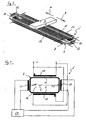
- An
der Primärspule 18 liegt Wechselspannung an. In Folge dieser Wechselspannung wird inden beiden Sekundärspulen 20 und 22 jeweils eine Spannung induziert. Bewegt sich das Bauteil, dessen Wegänderung und/oder Position mit Hilfe des Wegsensorsystems ermittelt werden soll, bewegt sich auch der mit diesem Bauteil bewegungsgekoppelteMagnet 4entlang der Primärspule 18. In Folge des Magnetfeldes desMagneten 4 wird derKern 6 im Bereich des Kernabschnitts 8 und des Kernabschnitts 10 auf Höhe desMagneten 4 in Sättigung gebracht, wodurch indem Kernabschnitt 8und dem Kernabschnitt 10 ein virtueller Luftspalt erzeugt wird. Hierdurch wird das Feld der Primärspule 18 differenziell in zwei Einzelfelder aufgeteilt, wobei die Einzelfelder inden Sekundärspulen 20 und 22 zur Position desMagneten 4 proportionale Induktionsspannungen erzeugen. Diese Induktionsspannungen werden inder Auswerteeinrichtung 24, bei der es sich beispielsweise um einen Mikrocontroller handeln kann, erfasst und dort z.B. mittels einer Subtraktionsschaltung oder einer Verhältnisbildung zu einem Wert für die Position des Bauteils weiterverarbeitet.
- At the
primary coil 18 is AC voltage. As a result of this alternating voltage, a voltage is respectively induced in the twosecondary coils magnet 4 coupled with this component also moves along theprimary coil 18. As a result of the magnetic field of themagnet 4, thecore 6 will be in the region of thecore portion 8 and thecore portion 10 at the level of themagnet 4 brought into saturation, whereby in thecore portion 8 and thecore portion 10, a virtual air gap is generated. As a result, the field of theprimary coil 18 is differentially divided into two individual fields, wherein the individual fields in thesecondary coils magnet 4 proportional induction voltages produce. These induction voltages are detected in theevaluation device 24, which may be, for example, a microcontroller, and further processed there, for example, by means of a subtraction circuit or a ratio formation to a value for the position of the component.
- 2, 2'2, 2 '
- - Sensor- Sensor
- 44
- - Magnet- magnet
- 6, 6',6"6, 6 ', 6 "
- - Kern- Core
- 8, 8', 8"8, 8 ', 8 "
- - Kernabschnitt- Core section
- 10, 10', 10"10, 10 ', 10 "
- - Kernabschnitt- Core section
- 12, 12', 12"12, 12 ', 12 "
- - Kernabschnitt- Core section
- 14, 14', 14"14, 14 ', 14 "
- - Kernabschnitt- Core section
- 1616
- - Freifläche- open space
- 18, 18', 18", 18"'18, 18 ', 18 ", 18"'
- - Primärspule- Primary coil
- 20, 20', 20",20"'20, 20 ', 20 ", 20"'
- - Sekundärspule- Secondary coil
- 22, 22', 22",22"'22, 22 ', 22 ", 22"'
- - Sekundärspule- Secondary coil
- 2424
- - Auswerteeinrichtung- Evaluation device
- 26, 26', 26", 26"'26, 26 ', 26 ", 26"'
- - Primärspule- Primary coil
- 2828
- - Isolierummantelung- Insulating jacket
- 30, 30', 30"30, 30 ', 30 "
- - Leiterbahnabschnitt- trace section
- 3232
- - Bohrung, Via-Bohrung- Hole, via hole
- 34, 34'34, 34 '
- - Leiterbahnabschnitt- trace section
- 3838
- - Erweiterung- Extension
- 4040
- - Spulenabschnitt- Coil section
- 4242
- - Spulenabschnitt- Coil section
- 4444
- - Spulenabschnitt- Coil section
- 4646
- - Spulenabschnitt- Coil section
- 4848
- - Leiterbahnabschnitt- trace section
- 5050
- - Leiterbahnabschnitt- trace section
- AA
- - Richtung- Direction
- BB
- - Richtung- Direction
- CC
- - Mittelachse- central axis
Claims (9)
- A magnetic displacement sensor system with at least one magnet (4) and at least one sensor (2, 2') which are movably arranged relative to one another, wherein the sensor (2, 2') comprises a soft-magnetic core (6, 6', 6") which encloses an inner free area (16), characterised in that two primary coils (18, 18', 18", 18"', 26, 26', 26", 26"') and two secondary coils (20, 20', 20", 20"', 22, 22' 22", 22"') are arranged on the core (6, 6', 6"), wherein the magnet (4) is arranged outside the area spanned by the core (6, 6', 6") and is designed for producing a magnetic saturation in the core (6, 6', 6"), and the core (6, 6', 6") comprises two linear core sections (8, 8', 8", 10, 10', 10") which are aligned parallel to one another and which at their axial ends are each connected to a core section (12, 12' 12", 14, 14', 14") connecting in a transverse or arched manner, and wherein in each case a secondary coil (20, 20', 20", 20"', 22, 22' 22", 22"') is arranged on the two core sections (12, 12' 12", 14, 14', 14") connecting in a transverse or arched manner.
- A magnetic displacement sensor system according to claim 1, with which the core (6) forms an essentially rectangular frame.
- A magnetic displacement sensor system according to one of the preceding claims, with which the first (18, 18', 18", 18"') and the second primary coil (26, 26', 26", 26"') are arranged on two core sections (8, 8', 8", 10, 10', 10") which are arranged lying opposite one another.
- A magnetic displacement sensor system according to one of the preceding claims, with which the primary coils (18', 18", 18"', 26', 26", 26"') and/or the secondary coils (22', 22", 22"') are formed from strip conductors (30, 30', 30") which are connected to one another.
- A magnetic path sensor system according to claim 4, with which the strip conductors (30) are connected to one another by way of Via-holes.
- A magnetic displacement sensor system according to claim 4, with which the strip conductors (30', 30") are connected to one another by way of lateral connections (34, 34').
- A magnetic displacement sensor system according to one of the claims 4 to 6, with which the core (6, 6', 6") comprises an insulation casing (28).
- A magnetic displacement sensor system according to claim 7, with which an evaluation device (24) for determining the position of the magnet (4) is arranged on the insulation casing (28).
- A magnetic displacement sensor system according to one of the preceding claims, with which the magnet (4) and the sensor (2, 2') are arranged on sides of a wall which are away from one another.
Priority Applications (1)
| Application Number | Priority Date | Filing Date | Title |
|---|---|---|---|
| EP20080013718 EP2149784B1 (en) | 2008-07-31 | 2008-07-31 | Magnetic path sensor system |
Applications Claiming Priority (1)
| Application Number | Priority Date | Filing Date | Title |
|---|---|---|---|
| EP20080013718 EP2149784B1 (en) | 2008-07-31 | 2008-07-31 | Magnetic path sensor system |
Publications (2)
| Publication Number | Publication Date |
|---|---|
| EP2149784A1 EP2149784A1 (en) | 2010-02-03 |
| EP2149784B1 true EP2149784B1 (en) | 2012-04-04 |
Family
ID=40134865
Family Applications (1)
| Application Number | Title | Priority Date | Filing Date |
|---|---|---|---|
| EP20080013718 Expired - Fee Related EP2149784B1 (en) | 2008-07-31 | 2008-07-31 | Magnetic path sensor system |
Country Status (1)
| Country | Link |
|---|---|
| EP (1) | EP2149784B1 (en) |
Cited By (2)
| Publication number | Priority date | Publication date | Assignee | Title |
|---|---|---|---|---|
| CN105008862A (en) * | 2013-03-01 | 2015-10-28 | 大陆-特韦斯贸易合伙股份公司及两合公司 | Sensor for detecting a position of a transducer magnet |
| WO2020104656A1 (en) | 2018-11-22 | 2020-05-28 | Vitesco Technologies Germany Gmbh | Magnetic position sensor system and sensor module |
Families Citing this family (5)
| Publication number | Priority date | Publication date | Assignee | Title |
|---|---|---|---|---|
| DE102012005344B4 (en) * | 2012-03-16 | 2014-12-18 | Tyco Electronics Amp Gmbh | TOUCH-FREE CONTACTOR ACCORDING TO THE PLCD PRINCIPLE |
| DE102012215862B4 (en) * | 2012-09-06 | 2022-10-06 | Deutsches Zentrum für Luft- und Raumfahrt e.V. | Surface mount choke |
| KR102160324B1 (en) | 2013-02-01 | 2020-09-25 | 콘티넨탈 테베스 아게 운트 코. 오하게 | Method for producing a sensing device |
| US9577185B1 (en) * | 2016-04-28 | 2017-02-21 | Texas Instruments Incorporated | Fluxgate device with low fluxgate noise |
| US11333529B2 (en) | 2018-05-22 | 2022-05-17 | Swoboda Schorndorf KG | Magnetic position sensor |
Family Cites Families (19)
| Publication number | Priority date | Publication date | Assignee | Title |
|---|---|---|---|---|
| US3480854A (en) * | 1964-11-09 | 1969-11-25 | Sybron Corp | Movable magnet magnetic flux transducers and transduction systems for indicating magnet position |
| GB1347329A (en) * | 1971-01-27 | 1974-02-27 | Westinghouse Electric Corp | Magnetic position indicator |
| DE2415232A1 (en) * | 1974-03-29 | 1975-10-02 | Philips Patentverwaltung | Electromagnetic inductive displacement transducer - has improved ratio between length and effective stroke |
| US4380928A (en) * | 1980-08-29 | 1983-04-26 | Aisin Seiki Company, Limited | Rotational angle sensor |
| DE3610479A1 (en) | 1986-03-27 | 1987-10-01 | Vacuumschmelze Gmbh | MAGNETIC TRAVEL SENSOR |
| DE4425904A1 (en) | 1994-07-21 | 1996-01-25 | Vacuumschmelze Gmbh | Magnetic displacement sensor |
| DE4425903C2 (en) | 1994-07-21 | 1997-03-20 | Siemens Ag | Device with a measuring transformer for detecting the position of a linearly movable object |
| DE69837694T2 (en) * | 1997-05-21 | 2008-01-10 | Sony Manufacturing Systems Corp., Kuki | Magnetic metal probe and method of detecting a magnetic metal |
| DE19805621A1 (en) * | 1998-02-12 | 1999-08-19 | Hydraulik Ring Gmbh | Arrangement for contactless position determination of a measurement object, preferably a selector shaft of a motor vehicle transmission |
| DE19805783C2 (en) * | 1998-02-12 | 2000-06-08 | Siemens Ag | Arrangement for two-dimensional, contactless position determination of a measurement object |
| DE19919424A1 (en) | 1999-04-28 | 2000-11-30 | Tyco Electronics Logistics Ag | Magnetic position sensor, its use and manufacture |
| DE10139707A1 (en) * | 2001-08-11 | 2003-02-20 | Philips Corp Intellectual Pty | circuit board |
| KR100432661B1 (en) * | 2002-03-09 | 2004-05-22 | 삼성전기주식회사 | A weak-magnetic field sensor using printed circuit board and its making method |
| DE10354694C5 (en) * | 2003-11-22 | 2008-10-09 | Sick Ag | Inductive sensor |
| DE102004004100B4 (en) * | 2004-01-27 | 2007-02-01 | Siemens Ag | Position sensor and corresponding method for detecting the position of a rotating body |
| DE102004016622B4 (en) * | 2004-04-03 | 2008-11-27 | Festo Ag & Co. Kg | Position sensor arrangement |
| KR100619368B1 (en) * | 2004-07-05 | 2006-09-08 | 삼성전기주식회사 | Printed circuit board having weak-magnetic field sensor and method for manufacturing the same |
| KR100619369B1 (en) * | 2004-07-24 | 2006-09-08 | 삼성전기주식회사 | Printed circuit board having weak-magnetic field sensor and method for manufacturing the same |
| FR2873807B1 (en) | 2004-07-27 | 2007-04-27 | Electricfil Automotive Soc Par | NON-CONTACT POSITION MAGNETIC SENSOR |
-
2008
- 2008-07-31 EP EP20080013718 patent/EP2149784B1/en not_active Expired - Fee Related
Cited By (2)
| Publication number | Priority date | Publication date | Assignee | Title |
|---|---|---|---|---|
| CN105008862A (en) * | 2013-03-01 | 2015-10-28 | 大陆-特韦斯贸易合伙股份公司及两合公司 | Sensor for detecting a position of a transducer magnet |
| WO2020104656A1 (en) | 2018-11-22 | 2020-05-28 | Vitesco Technologies Germany Gmbh | Magnetic position sensor system and sensor module |
Also Published As
| Publication number | Publication date |
|---|---|
| EP2149784A1 (en) | 2010-02-03 |
Similar Documents
| Publication | Publication Date | Title |
|---|---|---|
| EP2149784B1 (en) | Magnetic path sensor system | |
| EP3602785A1 (en) | Door handle assembly for a motor vehicle having a capacitive sensor and near-field communication | |
| EP0557608A1 (en) | Coil assembly | |
| EP2037286A1 (en) | Measuring device for measuring a magnetic field | |
| WO2006005766A1 (en) | Device for detecting a collision | |
| DE102008037893B4 (en) | Inductive conductivity sensor | |
| EP0814321B1 (en) | Inductive displacement sensor | |
| EP2302328B1 (en) | Positioning device with multiple crossing transmitter coil assembly | |
| WO2014111218A1 (en) | Coil arrangement having two coils | |
| DE10354694B4 (en) | Inductive sensor | |
| EP3245480B1 (en) | Inductive position determination | |
| EP3417245B1 (en) | Sensor | |
| DE102016216330A1 (en) | Flexible coil arrangement for a magnetoelectric displacement sensor, displacement sensor and manufacturing method | |
| EP3417244B1 (en) | Sensor | |
| EP0797078A1 (en) | Inductive sensor for measuring the angle of rotation | |
| DE102011010682B3 (en) | Coil arrangement for non-contact distance measurement sensor, has core tube around with measuring and compensation coils are wound, such that layers of buckling coil are wound in opposition to layer of measuring coil | |
| EP3557188B1 (en) | Magnetized piston rod for measuring displacement | |
| DE102019132963B4 (en) | Current measurement arrangement | |
| DE102018222569A1 (en) | Measuring device for determining a path and / or angle change between the measuring device and an opposite position element and measuring method | |
| DE102008011971A1 (en) | Magnetic position sensor system has magnet and sensor which is arranged relative to each other in movable manner, where sensor has soft magnetic core, on which two separately-spaced coil pairs are arranged | |
| DE102008047960A1 (en) | Annular coil for use in inductive conductivity sensor utilized for measuring conductivity of liquid medium, has electrical conductor with two conductive strip sections, where current flow in one of sections is directed against component | |
| EP1306649A1 (en) | Inductive sensor arrangement for determining a rotation or a displacement | |
| EP3884240A1 (en) | Magnetic position sensor system and sensor module | |
| DE102009058835A1 (en) | Sensor coil e.g. linear variable differential transformer, for determining degree of opening of electromagnetically controllable proportional valve of hydraulic/pneumatic system, has conductive strips formed on coil carrier geometry | |
| DE102020119985A1 (en) | Position sensor for determining the position of a valve stem of a control valve |
Legal Events
| Date | Code | Title | Description |
|---|---|---|---|
| PUAI | Public reference made under article 153(3) epc to a published international application that has entered the european phase |
Free format text: ORIGINAL CODE: 0009012 |
|
| AK | Designated contracting states |
Kind code of ref document: A1 Designated state(s): AT BE BG CH CY CZ DE DK EE ES FI FR GB GR HR HU IE IS IT LI LT LU LV MC MT NL NO PL PT RO SE SI SK TR |
|
| AX | Request for extension of the european patent |
Extension state: AL BA MK RS |
|
| 17P | Request for examination filed |
Effective date: 20100802 |
|
| 17Q | First examination report despatched |
Effective date: 20100827 |
|
| AKX | Designation fees paid |
Designated state(s): DE |
|
| GRAP | Despatch of communication of intention to grant a patent |
Free format text: ORIGINAL CODE: EPIDOSNIGR1 |
|
| GRAS | Grant fee paid |
Free format text: ORIGINAL CODE: EPIDOSNIGR3 |
|
| GRAA | (expected) grant |
Free format text: ORIGINAL CODE: 0009210 |
|
| AK | Designated contracting states |
Kind code of ref document: B1 Designated state(s): DE |
|
| REG | Reference to a national code |
Ref country code: DE Ref legal event code: R096 Ref document number: 502008006842 Country of ref document: DE Effective date: 20120531 |
|
| PLBE | No opposition filed within time limit |
Free format text: ORIGINAL CODE: 0009261 |
|
| STAA | Information on the status of an ep patent application or granted ep patent |
Free format text: STATUS: NO OPPOSITION FILED WITHIN TIME LIMIT |
|
| 26N | No opposition filed |
Effective date: 20130107 |
|
| REG | Reference to a national code |
Ref country code: DE Ref legal event code: R097 Ref document number: 502008006842 Country of ref document: DE Effective date: 20130107 |
|
| PGFP | Annual fee paid to national office [announced via postgrant information from national office to epo] |
Ref country code: DE Payment date: 20180705 Year of fee payment: 11 |
|
| REG | Reference to a national code |
Ref country code: DE Ref legal event code: R119 Ref document number: 502008006842 Country of ref document: DE |
|
| PG25 | Lapsed in a contracting state [announced via postgrant information from national office to epo] |
Ref country code: DE Free format text: LAPSE BECAUSE OF NON-PAYMENT OF DUE FEES Effective date: 20200201 |