EP3141869A1 - Phase-based position detection using termination blind resistors - Google Patents
Phase-based position detection using termination blind resistors Download PDFInfo
- Publication number
- EP3141869A1 EP3141869A1 EP15002662.3A EP15002662A EP3141869A1 EP 3141869 A1 EP3141869 A1 EP 3141869A1 EP 15002662 A EP15002662 A EP 15002662A EP 3141869 A1 EP3141869 A1 EP 3141869A1
- Authority
- EP
- European Patent Office
- Prior art keywords
- receiving module
- transmitting element
- longitudinal
- along
- conductor component
- Prior art date
- Legal status (The legal status is an assumption and is not a legal conclusion. Google has not performed a legal analysis and makes no representation as to the accuracy of the status listed.)
- Withdrawn
Links
Images


Classifications
-
- G—PHYSICS
- G01—MEASURING; TESTING
- G01D—MEASURING NOT SPECIALLY ADAPTED FOR A SPECIFIC VARIABLE; ARRANGEMENTS FOR MEASURING TWO OR MORE VARIABLES NOT COVERED IN A SINGLE OTHER SUBCLASS; TARIFF METERING APPARATUS; MEASURING OR TESTING NOT OTHERWISE PROVIDED FOR
- G01D5/00—Mechanical means for transferring the output of a sensing member; Means for converting the output of a sensing member to another variable where the form or nature of the sensing member does not constrain the means for converting; Transducers not specially adapted for a specific variable
- G01D5/12—Mechanical means for transferring the output of a sensing member; Means for converting the output of a sensing member to another variable where the form or nature of the sensing member does not constrain the means for converting; Transducers not specially adapted for a specific variable using electric or magnetic means
- G01D5/14—Mechanical means for transferring the output of a sensing member; Means for converting the output of a sensing member to another variable where the form or nature of the sensing member does not constrain the means for converting; Transducers not specially adapted for a specific variable using electric or magnetic means influencing the magnitude of a current or voltage
- G01D5/20—Mechanical means for transferring the output of a sensing member; Means for converting the output of a sensing member to another variable where the form or nature of the sensing member does not constrain the means for converting; Transducers not specially adapted for a specific variable using electric or magnetic means influencing the magnitude of a current or voltage by varying inductance, e.g. by a movable armature
- G01D5/2006—Mechanical means for transferring the output of a sensing member; Means for converting the output of a sensing member to another variable where the form or nature of the sensing member does not constrain the means for converting; Transducers not specially adapted for a specific variable using electric or magnetic means influencing the magnitude of a current or voltage by varying inductance, e.g. by a movable armature by influencing the self-induction of one or more coils
- G01D5/202—Mechanical means for transferring the output of a sensing member; Means for converting the output of a sensing member to another variable where the form or nature of the sensing member does not constrain the means for converting; Transducers not specially adapted for a specific variable using electric or magnetic means influencing the magnitude of a current or voltage by varying inductance, e.g. by a movable armature by influencing the self-induction of one or more coils by movable a non-ferromagnetic conductive element
- G01D5/2026—Mechanical means for transferring the output of a sensing member; Means for converting the output of a sensing member to another variable where the form or nature of the sensing member does not constrain the means for converting; Transducers not specially adapted for a specific variable using electric or magnetic means influencing the magnitude of a current or voltage by varying inductance, e.g. by a movable armature by influencing the self-induction of one or more coils by movable a non-ferromagnetic conductive element constituting a short-circuiting element
-
- G—PHYSICS
- G01—MEASURING; TESTING
- G01D—MEASURING NOT SPECIALLY ADAPTED FOR A SPECIFIC VARIABLE; ARRANGEMENTS FOR MEASURING TWO OR MORE VARIABLES NOT COVERED IN A SINGLE OTHER SUBCLASS; TARIFF METERING APPARATUS; MEASURING OR TESTING NOT OTHERWISE PROVIDED FOR
- G01D5/00—Mechanical means for transferring the output of a sensing member; Means for converting the output of a sensing member to another variable where the form or nature of the sensing member does not constrain the means for converting; Transducers not specially adapted for a specific variable
- G01D5/12—Mechanical means for transferring the output of a sensing member; Means for converting the output of a sensing member to another variable where the form or nature of the sensing member does not constrain the means for converting; Transducers not specially adapted for a specific variable using electric or magnetic means
- G01D5/14—Mechanical means for transferring the output of a sensing member; Means for converting the output of a sensing member to another variable where the form or nature of the sensing member does not constrain the means for converting; Transducers not specially adapted for a specific variable using electric or magnetic means influencing the magnitude of a current or voltage
- G01D5/20—Mechanical means for transferring the output of a sensing member; Means for converting the output of a sensing member to another variable where the form or nature of the sensing member does not constrain the means for converting; Transducers not specially adapted for a specific variable using electric or magnetic means influencing the magnitude of a current or voltage by varying inductance, e.g. by a movable armature
- G01D5/204—Mechanical means for transferring the output of a sensing member; Means for converting the output of a sensing member to another variable where the form or nature of the sensing member does not constrain the means for converting; Transducers not specially adapted for a specific variable using electric or magnetic means influencing the magnitude of a current or voltage by varying inductance, e.g. by a movable armature by influencing the mutual induction between two or more coils
- G01D5/2053—Mechanical means for transferring the output of a sensing member; Means for converting the output of a sensing member to another variable where the form or nature of the sensing member does not constrain the means for converting; Transducers not specially adapted for a specific variable using electric or magnetic means influencing the magnitude of a current or voltage by varying inductance, e.g. by a movable armature by influencing the mutual induction between two or more coils by a movable non-ferromagnetic conductive element
- G01D5/206—Mechanical means for transferring the output of a sensing member; Means for converting the output of a sensing member to another variable where the form or nature of the sensing member does not constrain the means for converting; Transducers not specially adapted for a specific variable using electric or magnetic means influencing the magnitude of a current or voltage by varying inductance, e.g. by a movable armature by influencing the mutual induction between two or more coils by a movable non-ferromagnetic conductive element constituting a short-circuiting element
-
- G—PHYSICS
- G01—MEASURING; TESTING
- G01D—MEASURING NOT SPECIALLY ADAPTED FOR A SPECIFIC VARIABLE; ARRANGEMENTS FOR MEASURING TWO OR MORE VARIABLES NOT COVERED IN A SINGLE OTHER SUBCLASS; TARIFF METERING APPARATUS; MEASURING OR TESTING NOT OTHERWISE PROVIDED FOR
- G01D5/00—Mechanical means for transferring the output of a sensing member; Means for converting the output of a sensing member to another variable where the form or nature of the sensing member does not constrain the means for converting; Transducers not specially adapted for a specific variable
- G01D5/12—Mechanical means for transferring the output of a sensing member; Means for converting the output of a sensing member to another variable where the form or nature of the sensing member does not constrain the means for converting; Transducers not specially adapted for a specific variable using electric or magnetic means
- G01D5/243—Mechanical means for transferring the output of a sensing member; Means for converting the output of a sensing member to another variable where the form or nature of the sensing member does not constrain the means for converting; Transducers not specially adapted for a specific variable using electric or magnetic means influencing the phase or frequency of ac
Definitions
- the present invention relates to a device and a method for position determination and in particular for contactless position, angle and / or motion measurement.
- US 4,007,454 discloses an apparatus for remotely sensing angular positions, velocities, and / or rotational directions of objects.
- a rotating electric field is generated in the vicinity of a rotating element, wherein the axes of rotation of the electric field and of the rotating element coincide.
- an electric field sensor is positioned to detect changes in the electric field as it passes the rotating element.
- the sensor generates an electrical output signal whose relative phase depends on the angular position of the rotating element.
- the rotating electric field is generated by six arranged on a circle electrodes, which are successively supplied periodically with electrical signals from a phase splitter.
- the object of the present invention is to provide an apparatus and a method for simpler and more cost-effective position determination with a high resolution capability and high measurement reliability. This object is achieved by a device having the features according to claim 1 and by a method according to claim 12. Preferred embodiments are subject of the dependent claims.
- each of the cross connections has a predetermined electrical reactance value X instead of the predetermined electrical resistance value R
- the first electrically conductive end connection instead of the first electrical reactance value X 1 has first electrical resistance value R 1 .
- the transmitting element is designed to generate a periodic magnetic field which causes the periodic electrical current flow or the periodic electrical voltage in the longitudinal conductor components of the receiving module.
- the phase relationship of a first periodic electrical voltage or current signal between the longitudinal conductor components at the first end portion as a first periodic signal relative to the phase position of the magnetic field depends on the position of the transmitting element relative to the phase relationship of the resistance elements in the cross connections and the reactance in the end connection or vice versa from the first end section.
- a periodic reference signal can in particular serve a periodic electrical signal, which has a known, fixed phase position (reference phase) relative to the magnetic field generated by the transmitting element.
- a second periodic signal which detects the evaluation device at the second end section can serve as the reference signal.
- the evaluation device is thus preferably designed to transmit the second periodic signal (eg second voltage signal or second Current signal) at the second end section and, depending on a phase difference between the first periodic signal and the second periodic signal, determine the position p of the transmitting element along the longitudinal extent x of the receiving module.
- the receiving module also particularly preferably comprises a second electrically conductive end connection, which connects the first longitudinal conductor component and the second longitudinal conductor component to one another at the second end portion.
- the second end connection preferably has a predetermined second electrical reactance value X 2 .
- the second end connection preferably has a predetermined second electrical resistance value R 2 .
- the phase position ⁇ 1 or ⁇ 2 depends, for example, on a voltage U 1 and / or U 2 used for the position determination relative to a reference phase position of a reference voltage from the position of the sensor element along the longitudinal extent.
- the position of the sensor element relative to the transmission module, in particular relative to its end sections, can be determined via the phase position ⁇ 1 and / or ⁇ 2 of the determined voltage relative to the reference phase value of the reference voltage.
- the reference voltage is also a periodically oscillating AC voltage.
- the determined electrical voltage or the determined phase position ⁇ 1 and / or ⁇ 2 is dependent on the position p of the sensor element along the longitudinal extent.
- the position of the sensor element along the longitudinal extension x of the receiving module, in particular relative to its end sections, can be determined or, for example, its center determined.
- the voltage U 2 can serve as a reference voltage for the voltage U 1 or vice versa.
- the phase position ⁇ 2 would then be the reference phase to the phase position ⁇ 1 or vice versa.
- the position p of the transmitting element can be determined along the longitudinal extension x as a function of a difference or a difference between the phase positions ⁇ 1 and ⁇ 2 .
- the position determination according to the invention is not dependent on the detection and evaluation of signal intensities.
- the position determination according to the invention is not dependent on an evaluation of the amplitude of the voltage U 1 and / or the voltage U 2 .
- the position determination based on the determination of relative phase angles of the voltages U 1 and / or U 2 to each other and / or to a reference phase, preferably substantially independent of their intensity.
- the invention achieves a high interference insensitivity or immunity to interference and a high resolution with comparatively simple means.
- the transmission module can be constructed comparatively simply.
- the position determination according to the invention has the advantage that intended and / or unintended changes in a distance between the transmitting element and the receiving module have essentially no influence on the position determination, since this has essentially no influence on the phase position ⁇ 1 and / or ⁇ 2 . While the amplitudes of the voltage U 1 and / or U 2 can become smaller at a greater distance of the transmitting element to the receiving module, this has essentially no influence on the phase positions ⁇ 1 and ⁇ 2 . Substantially no influence here means that typically expected small deviations of the distance between the transmitting element and the receiving module do not cause a reduction of the measuring accuracy, the one would make position determination impossible.
- the electrical voltage U 1 and the electrical voltage U 2 at the first end portion or at the second end portion of the receiving module is significantly determined by the induction of a current flow I ind or a voltage U ind in the longitudinal conductor components and in the cross-connections of the receiving module.
- the value of the voltage value U 1 at the first end section of the receiving module and the phase position ⁇ 1 relative to a phase position ⁇ ind of the induced voltage U ind depend in particular on the distance of the transmitting element from the first end section along the longitudinal extent x of the receiving module.
- the measured voltage value U 1 and the first phase position ⁇ 1 relative to a phase position ⁇ ind of the induced voltage U ind depend on the number of electrically conductive cross connections with predetermined resistances which extend between the first end section and the position of the transmitting element along the longitudinal extension x are located.
- the value of the voltage value U 2 at the second end section of the receiving module and the second phase position ⁇ 2 relative to the phase position ⁇ ind of the induced voltage U ind depend in particular on the distance of the transmitting element from the second end section along the longitudinal extent x of the receiving module.
- the measured voltage value U 2 and the second phase position ⁇ 2 relative to the phase position ⁇ ind of the induced voltage U ind depend on the number of electrically conductive cross-connections with predetermined resistances, which extend between the position of the transmitting element along the longitudinal extension x and the second End section are located.
- another alternating voltage can also serve as a reference voltage or as a reference phase position.
- the voltage value U 1 is greater the closer the transmitting element is to the first end section and the smaller the number of electrically conductive cross connections between the first end section and the position of the transmitting element, since thus the resulting electrical resistance of the parallel connections between the first End section and the position of the transmitting element increases.
- the further the position of the transmitting element is from the first end section, and the greater the number of electrically conductive transverse connections between the first end section and the position of the transmitting element the smaller is the voltage value U 1 , since this results in the resulting electrical resistance of the parallel connections between the first end portion and the position of the transmitting element decreases.
- the difference of the first phase position ⁇ 1 relative to the phase position ⁇ ind of the induced voltage U ind is also influenced or determined by the number of electrically conductive cross connections between the first end section and the position of the transmitting element.
- the voltage value V 2 is the larger, the transmission element is located nearer to the second end portion and the smaller the number of electrically conductive cross-connections with predetermined resistance between the second end portion and the position of the end member. Accordingly, the voltage value is U 2 the farther the position of the transmitting element is removed from the second end portion and the smaller and the larger the number of the electrically conductive cross connections with predetermined resistance between the second end portion and the position of the end member. Furthermore, the difference of the second phase angle ⁇ 2 relative to the phase position ⁇ ind of the induced voltage U ind is also influenced or determined by the number of electrically conductive cross connections between the second end section and the position of the transmitting element.
- the difference between the first phase position ⁇ 1 and / or the second phase position ⁇ 2 relative to one another and / or the phase position of the induced voltage ⁇ ind is determined by a phase angle of the complex impedance, which in turn is determined by the value of the (real) effective resistance and the value of imaginary reactance depends.
- the evaluation device is designed in such a way, from the first phase position ⁇ 1 and / or the second phase position ⁇ 2 relative to the reference signal or from the phase difference between the first periodic signal and the second periodic signal to determine the position of the transmitting element along the longitudinal extent x of the receiving module. For this it does not have to be necessary for the voltage values U 1 and / or U 2 and / or their respective phase position ⁇ 1 or ⁇ 2 itself to be measured by the measuring or evaluation device, but it may already be sufficient to produce a difference of two phase positions ⁇ 1 and ⁇ 2 to determine.
- the voltage U 1 and / or U 2 can be subjected to a change process before the evaluation of the phase position ⁇ 1 or ⁇ 2 , for example, to facilitate the evaluation.
- a process of change may include gain (voltage gain).
- gain voltage gain
- the first end connection and / or the second end connection each comprise a capacitor and / or a coil.
- the first electrical reactance substantially corresponds to the reactance of a capacitor and / or a coil which is or are formed in the first end connection.
- the second electrical reactance substantially corresponds to the reactance of a capacitor and / or a coil which is or are formed in the second end connection.
- Each end connection thus has a complex impedance in which the imaginary part of the impedance is nonzero. At least the imaginary portion of the impedance can be dependent in its amplitude and in its phase angle or angle of the oscillation frequency of the voltage applied to the respective end connection voltage or AC voltage.
- the impedance of each end connection may further include a real portion of the impedance, such as an ohmic resistance.
- the real resistance can be caused for example by additional components or components which are formed in the end connection, and / or determined by a line resistance be.
- the reactance of the end connection may substantially correspond to the capacitance of the capacitor.
- the reactance of the end connection may substantially correspond to the inductive reactance (inductance) of the coil.
- “Essentially” means that in addition parasitic charges or effects can occur, which contribute to the reactance.
- the first end connection and the second end connection can have identical capacitors and / or coils and thus have substantially the same reactance values.
- the first end connection and the second end connection may have different capacitors and / or coils and still have substantially similar reactance values or have different reactance values.
- Each end connection can have one or more capacitors and / or one or more coils. If several coils and / or capacitors are present in an end connection, these can be connected in parallel and / or in series.
- a plurality of capacitors may have different or equal capacitances and / or a plurality of coils may have different or similar inductances.
- each cross-connection substantially exclusively has an ohmic resistance, wherein preferably each of the predetermined electrical resistance values (R) of the cross-connections is determined essentially exclusively by the ohmic resistance.
- each cross connection of the plurality of cross connections, to which according to the invention the end connections do not count only has an effective resistance.
- the resistance of a cross connection is determined solely by a real value of an impedance of this cross connection, ie that the impedance of the cross connection substantially none has imaginary share or that this is equal to zero. "Essentially” means that nevertheless parasitic charges or effects can occur, which cause a reactance.
- a cross connection has exclusively an ohmic resistance.
- a cross connection may also have a reactance, i. have an impedance that has a real and a complex component that are nonzero.
- the real effective resistance and the imaginary reactance of the transverse connection must each be different, in particular different in their magnitude, to the effective resistance or reactance of each end connection.
- the first reactance value and / or the second reactance value at the frequency of the periodic signal generated by the transmitting element has at least 1 ⁇ and / or at most 10 k ⁇ , preferably at least 10 ⁇ and / or at most 1 k ⁇ , more preferably at least 20 ⁇ and / or at most 0.5 k ⁇ , even more preferably at least 30 ⁇ and / or at most 0.2 k ⁇ , most preferably at least 50 ⁇ and / or at most 0.1 k ⁇ .
- the indicated values of the reactances are imaginary resistances, i. around an imaginary part of a complex impedance.
- the transmitting element is designed, an alternating magnetic field having a frequency in the range of at least about 100 Hz, more preferably in the range of at least about 1 kHz, more preferably in the range of at least about 10 kHz and / or in a range of not more than about 10 MHz, more preferably in a range of not more than about 1 MHz, more preferably in a range of not more than about 100 kHz, most preferably in a range of about 10 kHz to about 50 kHz.
- the frequency of the alternating magnetic field is determined for a particular device and / or does not change during a measurement or position determination.
- the transmitting element to an electromagnetic resonant circuit, by the resonant frequency substantially the frequency of the alternating magnetic field is determined.
- the values for impedances and / or resistances and / or reactances given above correspond to the corresponding values at the resonant frequency of the resonant circuit, provided that the values depend on the oscillation frequency of an applied electrical voltage.
- the receiving module comprises a number of electrically conductive cross-links in the range of at least about 5, preferably in a range of at least about 20, more preferably in a range of at least about 50, and / or in a range of not greater than about 1000, more preferably in a range of not more than about 500, more preferably in a range of not more than about 200.
- the predetermined effective resistance values R of the plurality of electrically conductive cross-connections are each in the range of at least about 0.1 k ⁇ , preferably in a range of at least about 0.5 k ⁇ , more preferably in a range of at least about 1 k ⁇ and / or in one Range of not more than about 10 M ⁇ , more preferably in a range of not more than about 1 M ⁇ , more preferably in a range of not more than about 100k ⁇ , most preferably in a range of not more than about 10 k ⁇ .
- this is the respective real component, insofar as it relates to a complex impedance which also has an imaginary reactance.
- the transmitting element preferably comprises a conductor loop and / or a coil.
- the transmitting element preferably comprises an electrical resonant circuit which comprises the conductor loop and / or the coil and a capacitor.
- a capacitor formed in the transmitting element will be referred to below as a transmitting element capacitor in order to avoid confusion.
- a coil formed in the transmitting element is to be referred to below as a transmitting element coil in order to avoid confusion.
- the position determining device comprises a power supply device, wherein the power supply device comprises a Conductor loop comprises, which preferably extends substantially in a plane spanned by the first and the second longitudinal conductor component and which at least partially surrounds the receiving module and wherein the conductor loop of the power supply means preferably at least partially includes the first and the second longitudinal conductor component.
- the power supply device comprises a Conductor loop comprises, which preferably extends substantially in a plane spanned by the first and the second longitudinal conductor component and which at least partially surrounds the receiving module and wherein the conductor loop of the power supply means preferably at least partially includes the first and the second longitudinal conductor component.
- the transmitting element can be part of a transmitting module.
- the transmission module may comprise, in addition to the transmission element, one or more power supply devices for supplying power to the transmission element.
- the conductor loop is arranged in a plane which is at least partially parallel to a plane which is spanned by the two longitudinal conductor components of the receiving module.
- the transmitter element coil when using a transmitter element coil, is preferably arranged such that the longitudinal axis of the transmitter element coil, which runs through the centers of the inner surfaces spanned by the windings, is perpendicular to the plane which is spanned by the two longitudinal conductor components of the receiver module and / or perpendicular to a plane tangent to the two longitudinal conductor components in their nearest the transmitting element points.
- the transmitter element coil has at least two turns. Preferably, however, the number of turns is greater than two, such as 10, 50 or 100 turns. Also, a larger number of turns, such as several hundred or even more than 1000 turns, may be advantageous.
- the transmitter element coil may include a ferromagnetic core to increase and / or focus the magnetic flux generated in the coil.
- the core of the coil can be made for example of ferromagnetic materials and / or ferrites.
- the device for determining the position preferably comprises a power supply device.
- the electrical current in the conductor loop or in the transmitter element coil are provided by the power supply device.
- the power supply device may be designed such that it applies an electrical voltage to the conductor loop or to the transmitter element coil, which in turn causes a current flow through the conductor loop or through the coil.
- the transmitting element preferably comprises an electrical oscillating circuit which comprises the conductor loop and / or the transmitting element coil and a capacitor.
- the resonant circuit may have one or more resistors, which may comprise separately incorporated resistance elements and / or electrical resistances, in particular resistors, which otherwise occur. For example, such an otherwise occurring resistance by the line resistance in the electrical conductor of the resonant circuit or by the resistances of other electrical components in the resonant circuit occur.
- the transmitting element comprises a resonant circuit
- this offers the advantage that electromagnetic oscillations and / or a magnetic field oscillating with the resonant frequency of the oscillating circuit can occur in and around the transmitting element coil, even if a supply of the oscillating circuit with electrical power is no longer present.
- the power supply device may be formed as a DC voltage source, for example as a battery or as a DC power supply, which is designed to charge the transmitter element capacitor.
- the power supply device can also be designed as an alternating voltage source, for example as an alternating voltage power supply, which excites an alternating current flow in the transmitting element (transmitting element current), provided that the Power supply device is electrically connected to the resonant circuit of the transmission element.
- an oscillating circuit can alternatively or additionally also be supplied with electrical energy by inductive coupling.
- a power supply device which in turn is designed as a coil or as a conductor loop, and which generates an alteration of the magnetic flux in the transmission element coil of the resonant circuit of the transmitting element by means of an alternating current flow or a variable current flow in the power supply device, whereby an electrical voltage and / or an electrical current flow in the transmitting element (transmitting element current) is induced.
- the power supply device comprises a conductor loop, which in particular inductively couples to the transmitting element in order to supply it with the necessary energy or power.
- the conductor loop of the power supply device preferably extends substantially in a plane spanned by the first and the second longitudinal conductor component and at least partially surrounds the receiving module. "Substantially in a plane spanned by the first and the second longitudinal conductor component” means that the conductor loop runs in such a way that the transmitting element can be arranged at a small distance, for example at a distance of 1 mm to 10 mm, above the receiving module, without the positionability of the transmitting element is impaired by the power supply device.
- the resonant circuit of the transmitting element can be supplied with electrical power, regardless of at which position the transmitting element along the Longitudinal x of the receiving module is located.
- the transmitting element is supplied essentially continuously or continuously, ie in particular also during a measuring operation with electrical power.
- the transmitting element is supplied in particular with electrical power while no measuring operation is running. In this case, the transmitting element is somewhat charged while no measuring operation is in progress.
- the supply of electrical power and the measuring process take place alternately. In the following, the process of supplying electric power as a power cycle and the measuring process as a measuring cycle will be referred to.
- the conductor loop of the power supply device at least partially includes the first and the second longitudinal conductor component.
- the conductor loop of the power supply device is formed inter alia by the longitudinal conductor components of the receiving module.
- the longitudinal conductor components and a very low electrical resistance electrical interconnect at an end portion for powering the transmitting element may be connected to an AC voltage source.
- the longitudinal conductor components are to be separated from the voltage source in order to compensate for those of the Induction by the transmitting element resulting voltage values U 1 and / or U 2 or their phase angles ⁇ 1 and / or ⁇ 2 to measure.
- each cross connection preferably has an identical resistance value R.
- the cross-connections have an equidistant spacing between 1 mm and 200 mm. Even more preferably, the cross connections have one equidistant distance between 3 mm and 50 mm. Most preferably, the cross connections have an equidistant spacing between 5 mm and 15 mm.
- the cross connections have a length between 3 mm and 100 mm. Even more preferably, the cross connections have a length between 5 mm and 50 mm. Most preferably, the cross connections have a length between 10 mm and 20 mm.
- the electrical cross-connections are rectilinear and perpendicular to the longitudinal extent x of the longitudinal conductor components and the cross-connections all have the same length.
- the conductor longitudinal components are parallel to each other and the distance between the longitudinal conductor components is equal to the length of the cross connections.
- the method described for the device according to the invention applies analogously.
- the role of the electrically conductive cross-connections and the end connection can also be reversed so that each of the cross connections has a predetermined electrical reactance value X instead of the predetermined electrical resistance value R , while the first electrically conductive end connection instead of the first electrical reactance value X 1 has a first electrical resistance value R 1 .
- the position p of the transmitting element along the longitudinal extent x of the receiving module is preferably determined as a function of a phase shift of the first phase position ⁇ 1 of the first electrical voltage U 1 and / or the second phase position ⁇ 2 of the second electrical voltage U 2 relative to a reference phase of a reference voltage
- the reference voltage can be, for example, the voltage present in the resonant circuit of the transmitting element, such as at the transmitting element capacitor, and / or an externally provided AC voltage signal.
- the position of the transmitting element along the longitudinal extent x of the receiving module is particularly preferably determined as a function of a phase shift of the first phase position ⁇ 1 of the first electrical voltage U 1 relative to the second phase position ⁇ 2 of the second electrical voltage U 2 .
- the second phase position ⁇ 2 preferably serves as the reference phase for the first phase position ⁇ 1 or vice versa.
- this has the advantage that any interference that affects the induction of current or voltage through the transmitting element in the receiving module, on both voltage signals U 1 and U 2 and / or on both phase ⁇ 1 and ⁇ 2 substantially the same Have influence and thus can avoid negative influences on the position determination.
- the first phase position ⁇ 1 and / or the second phase position ⁇ 2 or the phase shift changes substantially linearly with a change in the position (p) of the transmitting element along the longitudinal extension (x) of the receiving module (12).
- the inventive method or device for position determination is designed such that the phase shift or the first phase position ⁇ 1 and / or the second phase position ⁇ 2 directly proportional to a change in position of the position p of the transmitting element along the longitudinal extent x of Reception module is x.
- a power supply device inductively couples to the transmitting element and induces an electrical current flow and / or an electrical voltage in the transmitting element.
- the transmitting element preferably inductively couples in a measuring cycle to the receiving module and induces an electrical current flow and / or an electrical voltage in the receiving module.
- the power cycle (LZ) and the measurement cycle (MZ) preferably overlap at least not completely in time.
- the first phase position ⁇ 1 and / or the second phase position ⁇ 2 or the phase shift is determined, in particular exclusively, during a measuring cycle in which no inductive power supply of the transmitting element takes place by the power supply device. This is to prevent electromagnetic interference caused by the inductive Power supply, the measurement of the voltages U 1 and U 2 and the first phase ⁇ 1 and / or the second phase ⁇ 2 or their relationship to each other and / or falsify to a reference phase position.
- inventive method and devices according to the invention are also suitable for a position determination in several dimensions or directions.
- multiple receiving modules can be ranked side by side.
- a plurality of receiving modules are preferably arranged side by side by devices for position determination such that their longitudinal conductor components run parallel to one another.
- the position determination of a transmitting element in one dimension, ie in one direction, is carried out as already described by means of a single corresponding receiving module, over which the transmitting element is located at the time of measurement.
- voltage values U 1 and U 2 are induced in the first end section and in the second end section of the longitudinal conductor components, ie at the end connections, so that the position of the transmitting element can be determined perpendicular to the longitudinal extent x of the longitudinal conductor components. by determining at which receiving module the maximum voltages U 1 and U 2 abut the end sections. The position determination in the other dimension or direction, ie along the longitudinal extent x of the longitudinal conductor components can then be carried out, as already described for the case of one-dimensional position determinations.
- the two-dimensional position determination takes place in that the receiving module is arranged running meandering. This makes it possible to realize the two-dimensional position determination by means of a single receiving module.
- the two-dimensional position determination takes place in that at least two receiving modules are arranged such that their longitudinal extensions x (and y) not parallel to each other, but in particular intersect each other.
- the longitudinal extensions x and y are perpendicular to one another, but it is also possible to use another angle adapted to the specific application.
- the two-dimensional position determination is carried out in particular in a region or a surface in which the two receiving modules substantially overlap, ie in which the magnetic field of the transmitting element (or its position to be determined) passes (or is) between the longitudinal conductor components of both receiving modules.
- Fig. 1 shows a schematic representation of a receiving module 12 of a preferred embodiment of a device according to the invention for position determination 10.
- the receiving module 12 includes a rectilinear, first longitudinal conductor component 14a and a parallel to the first longitudinal conductor component 14a formed second longitudinal conductor component 14b.
- the two longitudinal conductor components 14a and 14b are x i connected at a plurality of positions each defined by a plurality of electrically conductive cross-connections 16 electrically conductive to each other.
- the number of x max equidistantly arranged cross connections 16 at the positions x 1 to x max subdivides the receiving module 12 along the longitudinal extent x into x max-1 receiving module segments 12 a of equal size.
- Each cross connection 16 has a certain electrical resistance value R i , which is due to the line resistance and to a possibly formed additional effective resistance element 16 a.
- R i electrical resistance value
- an additional resistance element 16a in the form of an ohmic resistance is formed.
- Ohmic resistance in this context means that the active resistance element 16a in particular having a resistance value R i, which is preferably independent of the frequency of an alternating voltage is preferably used in the context of an inventive apparatus for determining the position 10th
- the proportion of the line resistance of the cross-connection 16 is negligible compared to the proportion of the resistance element 16a on the resistance value of the cross-connection 16, which is why it is assumed in the following that the resistance of the cross-connection 16 the Resistance value R i of the effective resistance element 16a corresponds.
- the resistive elements 16a of the plurality of interconnects 16 are formed identically so that the resistance values R i of the interconnections 16 are substantially equal.
- Substantially equal here means that the effective resistance elements 16a are similar in the context of usual manufacturing tolerances and have the same effective resistance values R i lying in this frame.
- the similarity of the effective resistance values R i of the multiplicity of cross connections 16 is not a mandatory prerequisite since the use of different resistance elements 16 a, with different but known resistance values R i, is also possible.
- a temporal change of the magnetic flux ⁇ in this context means that the derivative of the magnetic flux ⁇ is not equal to zero after the time: d ⁇ dt ⁇ 0
- the induction current flows essentially circularly through the longitudinal conductor components 14a and 14b and through the cross connections 16 and the end connections 19a and 19b.
- Circular means that the induction current flows in the second longitudinal conductor component 14b opposite to the current flow direction in the first longitudinal conductor component 14a and in the cross connections 16 between the position of the induction effect (receiving module segment in which the Flow change occurs) and the second end portion 18b opposite to the current flow direction in the cross connections 16 between the position of the induction action and the first end portion 18a flows.
- an induction current I ind flows in the opposite direction, respectively.
- This induction current I ind leads to a voltage drop with a first voltage value U 1 to the effective resistance elements 16a in the cross connections 16 between the first end portion 18a and the position of the induction effect and a voltage drop with a second voltage value U 2 to the effective resistance elements 16a in the cross connections 16 between the position of the induction action and the second end portion 18b.
- the induction current I ind causes a voltage drop in the first end connection 19a and the second end connection 19b.
- each end connection 19 a and 19 b each have a capacitor 17.
- the value or the height or the amplitude of the first voltage value U 1 depends on the number of cross connections 16 between the first end section 18 a and the position of the induction effect. If the induction effect occurs at the position p in the receive module segment, these are p cross connections. Accordingly, the value or the height or the amplitude of the second voltage value U 2 depends on the number of cross connections 16 ( p max -p cross connections) between the position of the induction effect and the second end section 18 b and the resistance values R i of the corresponding cross connections 16 ,
- R i denotes the effective resistance value of the respective transverse connection 16 at the position x i
- C 1 denotes the capacitance of the capacitor 17, ⁇ the oscillation circuit frequency of the induction voltage U ind and j the imaginary unit.
- the resistances R i and the reactance of the capacitor form a parallel connection of resistors, in which the induction current I ind is divided.
- the induced by the transmitting element 20 in the receiving module 12 induction voltage U ind is independent of the position p and therefore can be considered in some ways as a constant reference.
- both the impedances Z 1 and Z 2 in the first end section 19 a and in the second end section 19 b are dependent on the position p of the transmitting element along the longitudinal extent x of the receiving module.
- the voltages U 1 and U 2 which drop therefrom are dependent on the position p of the transmitting element with regard to their amplitude or their magnitude and their phase position ⁇ 1 or ⁇ 2 .
- the inventors have recognized that the position p of the transmitting element along the longitudinal extent x of the receiving module can be determined particularly efficiently as a function of the phase position ⁇ 1 and / or ⁇ 2 .
- the position-dependent phase position ⁇ 1 ( p ) of the voltage U 1 is calculated below from the known variables in order to allow a position determination of the transmitting element 20.
- U 1 U ind - 2 ⁇ 2 R 2 C 2 - p Max - p ⁇ p m + j ⁇ R C p Max - 2 p - 4 ⁇ 2 R 2 C 2 - p Max 2
- first phase position ⁇ 1 ( p ) and / or the second phase position ⁇ 2 ( p ) are dependent on the position p of the transmitting element along the longitudinal extent x of the receiving module. Therefore, depending on the first phase position ⁇ 1 (p) and / or the second phase position ⁇ 2 ( p ), the position p of the transmitting element can be determined.
- Fig. 2 shows a first preferred embodiment of a device according to the invention for determining position 10 with a transmitting element 20.
- the transmitting element 20 comprises an electromagnetic resonant circuit 22.
- the resonant circuit in turn has a resistor 24, which by a line resistance in the resonant circuit 22 and / or by a separately formed resistive element can be caused.
- the resonant circuit comprises a transmitter element capacitor 26, which is connected at each end to one end of a transmitter element coil 28.
- the transmitter element coil 28 may preferably have 100 turns wound with a diameter of about 5 mm.
- the diameter of the transmitting element coil 28 or the windings perpendicular to the central axis of the transmitting element coil 28 can be chosen freely in its shape.
- a round or a square shape can be selected, which are adapted in their dimensions to the dimensions of the receiving module segments 12a.
- such an adaptation is particularly efficient if the surface extent of the temporal change of the magnetic flux change d ⁇ / dt in the plane spanned by the first longitudinal conductor component 14a and the second longitudinal conductor component 14b corresponds approximately to the dimensions of a receiving module segment 16a.
- the dimensions used for such an adaptation can be determined, for example, by averaging over all the reception module segments 12a.
- the transmitter element coil 28 includes a coil core 30.
- This may include ferromagnetic materials (such as Fe, Ni and / or Co) and / or ferromagnetic alloys (such as AlNiCo and / or SmCo and / or Permalloy).
- the coil core 30 ferrimagnetician, in particular electrically poorly conductive or non-conductive, substances such as ferrites (for example, hematite Fe 2 O 3 or magnetite Fe 3 O 4 ) have. Ferrites have the advantage that loss-making eddy currents in the coil core 30 can be suppressed by the poor or nonexistent conductivities.
- the spool core 30 is preferably adapted to the internal dimensions of the transmitter element coil 28 and fills these out.
- the transmitting element coil 28 has a round cross section with an inner diameter of 5 mm and a length of 50 mm
- a spool core 30 also having a circular cross section of 5 mm diameter and 50 mm length, so that this through the Windings of the transmitting element coil 28 spanned inner volume of the coil 28 as well as possible fills.
- the coil core 30 may also have a greater length than the transmitting element coil 28 and project beyond it.
- the distance between transmitting element coil 28 and coil core 30 or transmitting element 20 to the receiving module 12 can be selected to be very small, for example in the range of 1 mm to 5 mm. Due to such a small distance between the transmitting element 20 and the receiving module 12, the temporal change of the magnetic flux ⁇ in the receiving module 12, which is caused by induction due to a transmitting element current I se , are maximized.
- the position determining apparatus 10 may also have other shapes and / or sizes of the spool core 30 and / or arrangements of the transmitting element coil 28 about the spool core 30.
- further preferred embodiments may comprise a substantially U-shaped or horseshoe-shaped coil core 30, which may be partially or completely wrapped by the transmitter element coil 28.
- the induction of electrical power from the transmitting element 20 into the receiving module 12 can be particularly efficient if one end of the U-shaped or horseshoe-shaped spool core 30 is located directly above the receiving module 12 and the other end of the spool core 30 directly below the receiving module 12 is arranged.
- the induction can be particularly efficient when the receiving module 12 passes through the "open" end of the U-shaped or horseshoe-shaped spool core 30.
- the transmitter element coil 28 can be wound, for example, along the entire coil core 30 from one end of the coil core 30 to the other end of the coil core 30, or only along a portion of the coil core 30. In this way, for example, a particularly efficient leadership or bundling of magnetic field lines through the receiving module 12 can be achieved.
- an E core (core in "E" shape) is used as the coil core, wherein in particular the central web for coupling the alternating magnetic field in a region between the longitudinal conductor components 14a, 14b and the outer webs of the E core for returning the magnetic field in each case outside the first or second longitudinal conductor component is used.
- a time-varying transmission element current I se in the resonant circuit 22 of the transmitting element 20 is formed in the transmitting element coil 28 a time-varying magnetic field.
- the coil core 30 enhances the formation of this magnetic field.
- the resonant frequency at which the voltage and the transmitting element current I se oscillates in the resonant circuit 22 after termination of the power supply is determined in the preferred embodiment shown mainly by the capacitance of the capacitor 26 and the inductance of the transmitting element coil 28.
- another oscillator for example a quartz oscillator, may also be used in the transmitting element.
- the oscillation by the transmission element coil 28 transmitting element current I caused se in the receiving module 12 locally a temporal change of the magnetic flux ⁇ , which follows the temporal change of the transmission element current I se. Accordingly, in the receiving module 12, an induction current I ind is excited, which also follows the time change of the transmission element current I se .
- the induced current I ind causes the occurrence of voltage signals at the first end portion 18a and at the second end portion 18b of the receiving module 12, which respectively have the voltage value U 1 and U 2 .
- the voltage values U 1 and U 2 also follow the time change of the transmission element current I se .
- the voltage values U 1 and U 2 at the end sections 18a and 18b can have a different phase position ⁇ 1 or ⁇ 2 , which is decisively influenced by the respective reactance of the end connections 19a or 19b, in particular by a capacitor formed therein and / or one therein formed coil, are caused.
- a power supply conductor 32 This comprises a conductor loop, which runs around the receiving module 12 in the plane spanned by the first longitudinal conductor component 14a and by the second longitudinal conductor component 14b.
- a power supply device which preferably comprises the power supply conductor 32
- the transmitting element 20 can be supplied with electrical power.
- a time-varying power supply current I LV is generated in the power supply conductor 32 by the power supply device.
- a transmission element current I se be induced and the resonant circuit 22 are excited to vibrate. This is particularly efficient when the power supply current I LV is formed in the power supply conductor 32 as an alternating current, which oscillates with the resonant frequency of the resonant circuit 22.
- a phase-locked loop (PLL) is used (not shown), which determines the oscillation frequency of the power supply current I LV such that it minimizes deviation from the resonant frequency of the resonant circuit 22 has.
- PLL phase-locked loop
- the resonant frequency can be determined from the current induced by the resonant circuit 22 in the power supply conductor 32.
- the resonant circuit is first excited with an excitation signal which contains the resonance frequency of the resonant circuit or is close to the resonant frequency of the resonant circuit in order subsequently to determine from the "response" of resonant circuit 22 its resonance frequency. Should In the first attempt no sufficient power supply of the resonant circuit 22 take place, the process can be repeated with other oscillation frequencies of the excitation signal.
- Such a power supply of the oscillating circuit 22 by means of a power supply conductor 32 offers the advantage that the transmitting element 20 does not have to be wired for power supply and that no batteries or other power sources requiring renewal must be provided in the movable transmitting element 20. This makes it possible to reduce the complexity and the size of the transmitting element 20 and to avoid disturbing influences on its mobility by a possible wiring.
- Fig. 3 shows a second preferred embodiment of a device according to the invention for determining the position 10. Descriptions of components of the device for position determination 10 according to the invention, which are already in the context of in Fig. 2 are discussed, are analogous to the second embodiment, if any, applicable and are therefore not discussed again.
- the power supply conductor 32 has multiple turns.
- the power supply conductor 32 may have three turns around the receiving module 12. This has the effect of multiplying the change in the magnetic flux within the turns of the power supply conductor 32 caused by the power supply current I LV and the resulting induction of the transmitter element current I se by approximately the number of turns.
- a lower power supply current I LV may be sufficient to effect efficient powering of the transmitting element 20.
- the power supply current I LV may have a value of 20 mA (milliamperes).
- the power supply conductor 32 three turns This causes approximately an induction of a transmission element current I se , for which in the case of only one conductor loop in the power supply conductor 32 a power supply current I LV of 60 mA would be necessary.
- other multiplication values are possible by a correspondingly different number of turns.
- Fig. 4 shows a third preferred embodiment of a device according to the invention for determining the position 10. Descriptions of components of the device for position determination 10, which are already in the context of in Fig. 2 or Fig. 3 Embodiments discussed are analogous to the third embodiment, if any, applicable and will therefore not be discussed again.
- the power supply conductor 32 includes the first longitudinal conductor component 14a and the second longitudinal conductor component 14b of the receiving module. That is, the two longitudinal conductor components 14a and 14b serve on the one hand as a power supply conductor 32 to inductively supply the transmitting element 20 with electrical power and on the other hand serve as part of the receiving module 12 to guide the induced by the transmitting element 20 induction current I ind .
- a plurality of switching contacts 34 are provided in the embodiment described.
- the longitudinal conductor components 14a and 14b on the one hand by the power supply device (not shown), in particular by a power supply of the power supply device, separated and on the other hand can be interrupted at the other end portion 18b formed electrical short circuit of the two longitudinal conductor components 14a and 14b.
- Said electrical short is required for use as a power supply conductor 32 for powering the transmitting element 20 by means of the power supply device,
- the electrical short circuit would be a hindrance during the measurement of the voltage values U 1 and U 2 or during the determination of the phase angle ⁇ 1 and / or ⁇ 1 .
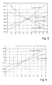
- Fig. 5 shows diagrams of progressions of the first phase ⁇ 1 and the second phase position ⁇ 2 as a function of the position p of the transmitting element for various preferred embodiments.
- the phases of the phase positions ⁇ 1 and ⁇ 2 are plotted for two different devices 10, which are identical in the parameters set out above, but which differ in the capacitors 17 in the respective end connections 19 a and 19 b.
- the different capacitances which distinguish the two configurations of the device 10, thereby cause a different slope of the change of the phase positions ⁇ 1 and ⁇ 2 .
- the somewhat larger capacitance of 150 nF of the capacitors 17 results in a smaller slope of the change of the phase positions ⁇ 1 and ⁇ 2 with changing position p of the transmitting element 20 than the somewhat small capacitance of 68 nF of the capacitors 17.
- the device has greater sensitivity than the otherwise similar device, which, unlike the first configuration, each has a capacitor 17 having a capacitance of 150 nF in the first and the second end connection 19a and 19b.
- the dependence of the gradient of the course of the phase positions ⁇ 1 and ⁇ 2 can in particular be understood by the term ( ⁇ RC ) 2 in the denominator of the formulas for the first phase position ⁇ 1 and the second phase position ⁇ 2 increasing capacity C increases quadratically, while the remaining terms in the denominator, which depend on p, do not grow with increasing capacity C.
- the ( ⁇ RC ) 2 dominates the denominator or the phase position ⁇ 1 or ⁇ 2 and / or the further terms which depend on p become increasingly negligible.
- phase positions ⁇ 1 and ⁇ 2 can be expressed by the following formulas: ⁇ 1 p ⁇ arctan 1 ⁇ RC p - p Max 2 ⁇ 2 p ⁇ - arctan 1 ⁇ RC p - p Max 2
- FIG. 12 shows plots of phase shift characteristics between the first phase ⁇ 1 and the second phase ⁇ 2 as a function of the position p of the transmission element for the two different configurations of the device 10 already described with reference to FIG Fig. 5 have been described.
- Fig. 6 It can be seen in this case also includes the graph of the phase shift ⁇ ⁇ (p) has a different slope for different capacitances of the capacitors 17 in the final compounds 19a and 19b.
- the deviations from a linear course are smaller than in the graphs of the individual phase positions ⁇ 1 and ⁇ 2 . This may be due, for example, to the fact that the contributions which lead to the deviation at least partially fall out during the subtraction or during the phase shift ⁇ ( p ).
- Figs. 7A to 7C show schematic representations of the time course of different voltage variables in a preferred embodiment of a device according to the invention for determining the position during operation.
- Fig. 7A shows the time course of the electrical voltage U ind , which is induced by the transmitting element 20 in the receiving module 10.
- Figs. 7B and 7C show the voltage U 1 and U 2 dropping at the first end connection 19 a and at the second end connection 19 B, respectively.
- the illustrated time profiles of the respective voltages are limited to a measurement cycle MZ, ie the course of the voltage during the power cycle LZ is not shown, since this is typically not taken into account for the position determination.
- a vertical auxiliary line VH which extends over all three figures Figs. 7A to 7C extends, marks an arbitrary point in time at which the respective phase angle ⁇ ind the induced voltage U ind , the first phase position ⁇ 1 of the first voltage U 1 and the second phase position ⁇ 2 of the second voltage U 2 are considered. It can be seen that the three voltages U ind , U 1 and U 2 do not oscillate in phase, but that the first phase ⁇ 1 of the voltage U1 and the second phase ⁇ 2 of the voltage U 2 both with each other and from the phase position of the induced Voltage U ind are different.
- the differences in the phase positions are due to the reactances in the end connections 19a and 19b, which cause a phase shift of the voltage signal falling in the end connections 19a and 19b relative to the induced voltage U ind .
- the differences in the phase positions are dependent on p, ie on the number of electrically conductive cross connections 16, which are located between the respective end connection 19a or 19b and the position of the transmitting element 20 along the longitudinal extension x of the receiving module 12.
- phase position ⁇ 1 and / or the phase position ⁇ 2 relative to one another and / or relative to the phase position of the induced voltage U ind as the reference phase and / or the phase shift or phase difference between ⁇ 1 and ⁇ 2 are used, in accordance with the invention, the position p of the transmission module along the longitudinal extension x of the reception module to investigate.
- the invention has been described in some embodiments, especially on the basis of the implementation with resistance values in the interconnections and reactance values in the end connections, it can also be used in an analogous manner with the reversed roles of active and Reactance values are implemented and used.
- the implementations of the components and / or numerical values of the first and / or second electrical reactance values in the respective end connection of the first implementation are also transferable to the predetermined electrical reactance values in the plurality of interconnections in the second implementation.
- the explanations concerning the components and / or numerical values of the predetermined electrical resistance values in the cross connections of the first implementation are preferably also applicable to the first and / or second electrical resistance value in the respective end connection of the second implementation.
Abstract
Die Erfindung betrifft ein Verfahren zur Positionsbestimmung sowie eine Vorrichtung zur Positionsbestimmung (10). Die Vorrichtung umfasst dabei in einer Implementierung: - zumindest ein Empfangsmodul (12) mit zumindest einer ersten und einer zweiten Längsleiterkomponente (14a, 14b), die sich entlang einer Längserstreckung (x) des Empfangsmoduls (12) von einem ersten Endabschnitt (18a) des Empfangsmoduls (12) zu einem zweiten Endabschnitt (18b) des Empfangsmoduls (12) erstrecken; einer Vielzahl von elektrisch leitenden Querverbindungen (16), welche an einer Vielzahl von Positionen ( x i ) entlang der Längserstreckung (x) des Empfangsmoduls (12) die erste und die zweite Längsleiterkomponente (14a, 14b) elektrisch leitend miteinander verbinden, wobei jede Querverbindung (16) einen vorbestimmten elektrischen Wirkwiderstandswert (R) aufweist; und zumindest eine erste elektrisch leitende Endverbindung (19a), welche am ersten Endabschnitt (18a) die erste Längsleiterkomponente (14a) und die zweite Längsleiterkomponente (14b) miteinander verbindet, wobei die erste Endverbindung (19a) einen vorbestimmten ersten elektrischen Blindwiderstandswert ( X 1 ) aufweist; - ein entlang der Längserstreckung (x) relativ zum Empfangsmodul (12) bewegbares Sendeelement (20), welches ausgelegt ist, im Empfangsmodul einen periodischen elektrischen Stromfluss ( I ind ) und/oder eine periodische elektrische Spannung ( U ind ) zu induzieren; - eine Auswerteeinrichtung, welche ausgelegt ist, ein erstes periodisches Signal ( U 1 ) am ersten Endabschnitt zu erfassen und abhängig von einer von einer Position (p) des Sendeelements (20) entlang der Längserstreckung (x) des Empfangsmoduls (12) abhängigen Phasenverschiebung zwischen dem ersten periodischen Signal ( U 1 ) und einem periodischen Referenzsignal die Position (p) des Sendeelements (20) entlang der Längserstreckung (x) des Empfangsmoduls (12) zu bestimmen.The invention relates to a method for position determination and to a device for position determination (10). The device comprises in one implementation: - At least one receiving module (12) having at least a first and a second longitudinal conductor component (14a, 14b) extending along a longitudinal extent (x) of the receiving module (12) from a first end portion (18a) of the receiving module (12) to a second end portion (18b) of the receiving module (12); a plurality of electrically conductive cross-connections (16), which at a plurality of positions (xi) along the longitudinal extension (x) of the receiving module (12) connect the first and the second longitudinal conductor components (14a, 14b) in an electrically conductive manner, each cross-connection ( 16) has a predetermined electrical resistance value (R); and at least one first electrically conductive end connection (19a) which connects the first longitudinal conductor component (14a) and the second longitudinal conductor component (14b) at the first end section (18a), wherein the first end connection (19a) has a predetermined first electrical reactance value (X 1). having; a transmitting element (20) which is movable along the longitudinal extent (x) relative to the receiving module (12) and which is designed to induce a periodic electrical current flow (I ind) and / or a periodic electrical voltage (U ind) in the receiving module; - An evaluation device which is designed to detect a first periodic signal (U 1) at the first end portion and depending on a of a position (p) of the transmitting element (20) along the longitudinal extent (x) of the receiving module (12) dependent phase shift between the position (p) of the transmitting element (20) along the longitudinal extension (x) of the receiving module (12) to determine the first periodic signal (U 1) and a periodic reference signal.
Description
Die vorliegende Erfindung betrifft eine Vorrichtung und ein Verfahren zur Positionsbestimmung und insbesondere zur kontaktlosen Positions-, Winkel- und/oder Bewegungsmessung.The present invention relates to a device and a method for position determination and in particular for contactless position, angle and / or motion measurement.
Derzeit übliche Positions- oder Wegsensoren arbeiten beispielsweise mit Bändern, in die kleine Dauermagnete implementiert sind. Die Position dieser kleinen Magnete wird über magnetfeldabhängige Widerstände erfasst. Die aktuelle Position bzw. Lage zwischen den Magneten und den magnetfeldabhängigen Widerständen wird ausgezählt, d.h. die Anzahl der Magnete, die von den Widerständen passiert wurde, wird detektiert und damit die Position der Widerstände relativ zu den Magneten ermittelt. Zur Verbesserung der räumlichen Auflösung wird oft eine analoge Zwischeninterpolation vorgenommen. Für eine sichere Funktion müssen die magnetfeldabhängigen Widerstände nah am Magnetband positioniert sein.Currently common position or displacement sensors, for example, work with bands in which small permanent magnets are implemented. The position of these small magnets is detected by magnetic field dependent resistors. The current position between the magnets and the magnetic field dependent resistors is counted out, i. the number of magnets that has passed through the resistors is detected, thereby determining the position of the resistors relative to the magnets. To improve the spatial resolution, an analog intermediate interpolation is often performed. For safe operation, the magnetic field dependent resistors must be positioned close to the magnetic tape.
Ferner sind aus
Aufgabe der vorliegenden Erfindung ist es, eine Vorrichtung und ein Verfahren zur einfacheren und kostengünstigeren Positionsbestimmung mit einem hohen Auflösungsvermögen und großer Messzuverlässigkeit bereitzustellen. Diese Aufgabe wird durch eine Vorrichtung mit den Merkmalen nach Anspruch 1 und durch ein Verfahren gemäß Anspruch 12 gelöst. Bevorzugte Ausführungsformen sind Gegenstand der abhängigen Ansprüche.The object of the present invention is to provide an apparatus and a method for simpler and more cost-effective position determination with a high resolution capability and high measurement reliability. This object is achieved by a device having the features according to
In einem Aspekt betrifft die Erfindung somit eine Vorrichtung zur Positionsbestimmung, umfassend:
- zumindest ein Empfangsmodul mit
- -- zumindest einer ersten und einer zweiten Längsleiterkomponente, die sich entlang einer Längserstreckung x des Empfangsmoduls von einem ersten Endabschnitt des Empfangsmoduls zu einem zweiten Endabschnitt des Empfangsmoduls erstrecken;
- -- einer Vielzahl von elektrisch leitenden Querverbindungen, welche an einer Vielzahl von Positionen xi entlang der Längserstreckung x des Empfangsmoduls die erste und die zweite Längsleiterkomponente elektrisch leitend miteinander verbinden, wobei jede Querverbindung einen vorbestimmten elektrischen Wirkwiderstandswert R aufweist;
- -- eine erste elektrisch leitende Endverbindung, welche am ersten Endabschnitt die erste Längsleiterkomponente und die zweite Längsleiterkomponente miteinander verbindet, wobei die erste Endverbindung einen vorbestimmten ersten elektrischen Blindwiderstandswert X1 aufweist;
- ein entlang der Längserstreckung x relativ zum Empfangsmodul bewegbares Sendeelement, welches ausgelegt ist, im Empfangsmodul einen periodischen elektrischen Stromfluss Iind und/oder eine periodische elektrische Spannung Uind zu induzieren;
- eine Auswerteeinrichtung, welche ausgelegt ist, ein erstes periodisches Signal (z.B. Spannungssignal und/oder Stromsignal) am ersten Endabschnitt zu erfassen und abhängig von einer von einer Position p des Sendeelements entlang der Längserstreckung x des Empfangsmoduls abhängigen Phasenverschiebung zwischen dem ersten periodischen Signal und einem periodischen Referenzsignal die Position p des Sendeelements entlang der Längserstreckung x des Empfangsmoduls zu bestimmen.
- at least one receiving module with
- - At least a first and a second longitudinal conductor component extending along a longitudinal extent x of the receiving module from a first end portion of the receiving module to a second end portion of the receiving module;
- - A plurality of electrically conductive cross-connections, which at a plurality of positions x i along the longitudinal extension x of the receiving module, the first and the second longitudinal conductor component electrically conductively connect to each other, each cross-connection has a predetermined electrical resistance value R;
- - A first electrically conductive end connection, which connects the first longitudinal conductor component and the second longitudinal conductor component to each other at the first end portion, wherein the first end connection has a predetermined first electrical reactance value X 1 ;
- a transmitting element which is movable along the longitudinal extent x relative to the receiving module and which is designed to induce a periodic electrical current flow I ind and / or a periodic electrical voltage U ind in the receiving module ;
- an evaluation device, which is designed, a first periodic signal (For example, voltage signal and / or current signal) to detect at the first end portion and depending on a dependent on a position p of the transmitting element along the longitudinal extension x of the receiving module phase shift between the first periodic signal and a periodic reference signal, the position p of the transmitting element along the longitudinal extent x of To determine receiving module.
In analoger Weise kann die Rolle der elektrisch leitenden Querverbindungen und der Endverbindung auch vertauscht werden, so dass jede der Querverbindungen anstelle der vorbestimmten elektrischen Wirkwiderstandswerts R einen vorbestimmten elektrischen Blindwiderstandswert X aufweist, während andererseits die erste elektrisch leitende Endverbindung anstelle des ersten elektrischen Blindwiderstandswertes X1 einen ersten elektrischen Wirkwiderstandswert R1 aufweist.In an analogous manner, the role of the electrically conductive cross-connections and the end connection can also be reversed so that each of the cross connections has a predetermined electrical reactance value X instead of the predetermined electrical resistance value R, while on the other hand the first electrically conductive end connection instead of the first electrical reactance value X 1 has first electrical resistance value R 1 .
Insbesondere ist das Sendeelement dabei ausgelegt, ein periodisches Magnetfeld zu erzeugen, welches den periodischen, elektrischen Stromfluss bzw. die periodische, elektrische Spannung in den Längsleiterkomponenten des Empfangsmoduls bewirkt. Durch die Kombination aus Wirkwiderständen in den Querverbindungen und dem Blindwiderstand in der Endverbindung oder umgekehrt hängt die Phasenlage eines ersten periodischen elektrischen Spannungs- oder Stromsignals zwischen den Längsleiterkomponenten am ersten Endabschnitt als ein erstes periodisches Signal relativ zur Phasenlage des Magnetfeldes von der Position des Sendelements relativ zum ersten Endabschnitt ab. Durch die Erfassung einer entsprechenden relativen Phasenlage des ersten periodischen Signals lässt sich also diese Position ermitteln.In particular, the transmitting element is designed to generate a periodic magnetic field which causes the periodic electrical current flow or the periodic electrical voltage in the longitudinal conductor components of the receiving module. The phase relationship of a first periodic electrical voltage or current signal between the longitudinal conductor components at the first end portion as a first periodic signal relative to the phase position of the magnetic field depends on the position of the transmitting element relative to the phase relationship of the resistance elements in the cross connections and the reactance in the end connection or vice versa from the first end section. By detecting a corresponding relative phase angle of the first periodic signal, therefore, this position can be determined.
Als periodisches Referenzsignal kann dabei insbesondere ein periodisches elektrisches Signal dienen, welches eine bekannte, feste Phasenlage (Referenzphase) relativ zu dem vom Sendelement erzeugten Magnetfeld hat. In einer weiteren bevorzugten Ausführungsform kann als Referenzsignal ein zweites periodisches Signal dienen, welches die Auswerteeinrichtung am zweiten Endabschnitt erfasst. Dabei ist die Auswerteeinrichtung also vorzugsweise ausgelegt ist, das zweites periodisches Signal (z.B. zweites Spannungssignal oder zweites Stromsignal) am zweiten Endabschnitt zu erfassen und abhängig von einer Phasendifferenz zwischen dem ersten periodischen Signal und dem zweiten periodischen Signal die Position p des Sendeelements entlang der Längserstreckung x des Empfangsmoduls zu bestimmen. Besonders bevorzugt umfasst das Empfangsmodul dabei außerdem eine zweite elektrisch leitende Endverbindung, welche am zweiten Endabschnitt die erste Längsleiterkomponente und die zweite Längsleiterkomponente miteinander verbindet. Insbesondere im Fall von vorbestimmten elektrischen Wirkwiderstandswerten R in den Querverbindungen und dem ersten elektrischen Blindwiderstandswert X1 in der ersten Endverbindung weist die zweite Endverbindung vorzugsweise einen vorbestimmten zweiten elektrischen Blindwiderstandswert X2 auf. Analog weist vorzugsweise im Fall von vorbestimmten elektrischen Blindwiderstandswerten X in den Querverbindungen und dem ersten elektrischen Wirkwiderstandswert R1 in der ersten Endverbindung die zweite Endverbindung einen vorbestimmten zweiten elektrischen Wirkwiderstandswert R2 auf.As a periodic reference signal can in particular serve a periodic electrical signal, which has a known, fixed phase position (reference phase) relative to the magnetic field generated by the transmitting element. In a further preferred embodiment, a second periodic signal which detects the evaluation device at the second end section can serve as the reference signal. In this case, the evaluation device is thus preferably designed to transmit the second periodic signal (eg second voltage signal or second Current signal) at the second end section and, depending on a phase difference between the first periodic signal and the second periodic signal, determine the position p of the transmitting element along the longitudinal extent x of the receiving module. In this case, the receiving module also particularly preferably comprises a second electrically conductive end connection, which connects the first longitudinal conductor component and the second longitudinal conductor component to one another at the second end portion. In particular, in the case of predetermined electrical resistances R in the interconnections and the first electrical reactance value X 1 in the first end connection, the second end connection preferably has a predetermined second electrical reactance value X 2 . Similarly, in the case of predetermined electrical reactance values X in the cross connections and the first electrical resistance value R 1 in the first end connection, the second end connection preferably has a predetermined second electrical resistance value R 2 .
Insbesondere hängt dabei die Phasenlage ϕ 1 bzw. ϕ 2 beispielsweise einer für die Positionsbestimmung herangezogenen Spannung U1 und/oder U2 relativ zu einer Referenzphasenlage einer Referenzspannung von der Position des Sensorelements entlang der Längserstreckung ab. Über die durch die Sensoreinrichtung ermittelte Phasenlage ϕ 1 und/oder ϕ 2 der ermittelten elektrischen Spannung relativ zu dem Referenzphasenwert der Referenzspannung lässt sich die Position des Sensorelements relativ zum Sendemodul, insbesondere relativ zu dessen Endabschnitten bestimmen. Insbesondere ist dabei die Referenzspannung auch eine periodisch oszillierende Wechselspannung.In particular, the phase position φ 1 or φ 2 depends, for example, on a voltage U 1 and / or U 2 used for the position determination relative to a reference phase position of a reference voltage from the position of the sensor element along the longitudinal extent. The position of the sensor element relative to the transmission module, in particular relative to its end sections, can be determined via the phase position φ 1 and / or φ 2 of the determined voltage relative to the reference phase value of the reference voltage. In particular, the reference voltage is also a periodically oscillating AC voltage.
Die ermittelte elektrische Spannung bzw. die ermittelte Phasenlage ϕ 1 und/oder ϕ 2 ist dabei von der Position p des Sensorelements entlang der Längserstreckung abhängig. Über die ermittelte Phasenlage ϕ 1 bzw. ϕ 2 der Spannung an den Endabschnitten relativ zu einem periodischen Referenzsignal lässt sich somit die Position des Sensorelements entlang der Längserstreckung x des Empfangsmoduls, insbesondere relativ zu dessen Endabschnitten bestimmen oder beispielsweise dessen Mittelpunkt bestimmen.The determined electrical voltage or the determined phase position φ 1 and / or φ 2 is dependent on the position p of the sensor element along the longitudinal extent. By means of the determined phase position φ 1 or φ 2 of the voltage at the end sections relative to a periodic reference signal, the position of the sensor element along the longitudinal extension x of the receiving module, in particular relative to its end sections, can be determined or, for example, its center determined.
Beispielsweise kann die Spannung U2 als Referenzspannung für die Spannung U1 dienen oder umgekehrt. In diesem Falle wäre sodann die Phasenlage ϕ 2 die Referenzphase zur Phasenlage ϕ 1 oder umgekehrt. In anderen Worten kann die Position p des Sendelements entlang der Längserstreckung x in Abhängigkeit eines Unterschieds bzw. einer Differenz zwischen den Phasenlagen ϕ 1 und ϕ 2 bestimmt werden.For example, the voltage U 2 can serve as a reference voltage for the voltage U 1 or vice versa. In this case, the phase position φ 2 would then be the reference phase to the phase position φ 1 or vice versa. In other words, the position p of the transmitting element can be determined along the longitudinal extension x as a function of a difference or a difference between the phase positions φ 1 and φ 2 .
Dabei ist die erfindungsgemäße Positionsbestimmung nicht auf die Detektion und Auswertung von Signalintensitäten angewiesen. Insbesondere ist die erfindungsgemäße Positionsbestimmung nicht auf eine Auswertung der Amplitude der Spannung U1 und/oder der Spannung U2 angewiesen. Anstelle dessen basiert die Positionsbestimmung auf der Ermittlung relativer Phasenlagen der Spannungen U1 und/oder U2 zueinander und/oder zu einer Referenzphase, vorzugsweise im Wesentlichen unabhängig von deren Intensität. Damit erreicht die Erfindung eine hohe Störungsunempfindlichkeit bzw. Störfestigkeit und ein hohes Auflösungsvermögen mit vergleichsweise einfachen Mitteln. Insbesondere kann das Sendemodul vergleichsweise einfach aufgebaut sein.The position determination according to the invention is not dependent on the detection and evaluation of signal intensities. In particular, the position determination according to the invention is not dependent on an evaluation of the amplitude of the voltage U 1 and / or the voltage U 2 . Instead, the position determination based on the determination of relative phase angles of the voltages U 1 and / or U 2 to each other and / or to a reference phase, preferably substantially independent of their intensity. Thus, the invention achieves a high interference insensitivity or immunity to interference and a high resolution with comparatively simple means. In particular, the transmission module can be constructed comparatively simply.
Aufgrund der hohen Empfindlichkeit der erfindungsgemäßen Phasenauswertung kann eine sehr genaue Positionsbestimmung bereits mit sehr niedrigen elektrischen Feldstärken und somit bei überraschend geringem Energieverbrauch erreicht werden. Ferner hat die erfindungsgemäße Positionsbestimmung den Vorteil, dass beabsichtigte und/oder unbeabsichtigte Änderungen eines Abstands zwischen dem Sendelement und dem Empfangsmodul im Wesentlichen keinen Einfluss auf die Positionsbestimmung haben, da dies im Wesentlichen keinen Einfluss auf die Phasenlage ϕ 1 und/oder ϕ 2 hat. Während die Amplituden der Spannung U1 und/oder U2 bei einem größeren Abstand des Sendeelements zu dem Empfangsmodul kleiner werden können, hat dies im Wesentlichen keinen Einfluss auf die Phasenlagen ϕ 1 und ϕ 2. Im Wesentlichen keinen Einfluss bedeutet dabei, dass typischerweise zu erwartende kleine Abweichungen des Abstands zwischen dem Sendeelement und dem Empfangsmodul keine Reduktion der Messgenauigkeit verursachen, die eine Positionsbestimmung unmöglich machen würden.Due to the high sensitivity of the phase evaluation according to the invention, a very accurate position determination can already be achieved with very low electric field strengths and thus with surprisingly low energy consumption. Furthermore, the position determination according to the invention has the advantage that intended and / or unintended changes in a distance between the transmitting element and the receiving module have essentially no influence on the position determination, since this has essentially no influence on the phase position φ 1 and / or φ 2 . While the amplitudes of the voltage U 1 and / or U 2 can become smaller at a greater distance of the transmitting element to the receiving module, this has essentially no influence on the phase positions φ 1 and φ 2 . Substantially no influence here means that typically expected small deviations of the distance between the transmitting element and the receiving module do not cause a reduction of the measuring accuracy, the one Would make position determination impossible.
Die elektrische Spannung U1 und die elektrische Spannung U2 an dem ersten Endabschnitt bzw. an dem zweiten Endabschnitt des Empfangsmoduls wird dabei maßgeblich durch die Induktion eines Stromflusses Iind bzw. einer Spannung Uind in den Längsleiterkomponenten und in den Querverbindungen des Empfangsmoduls bestimmt. Der Wert des Spannungswertes U1 am ersten Endabschnitt des Empfangsmoduls sowie die Phasenlage ϕ 1 relativ zu einer Phasenlage ϕind der induzierten Spannung Uind hängt dabei insbesondere von der Entfernung des Sendelements vom ersten Endabschnitt entlang der Längserstreckung x des Empfangsmoduls ab. Insbesondere hängt der gemessene Spannungswert U1 sowie die erste Phasenlage ϕ 1 relativ zu einer Phasenlage ϕind der induzierten Spannung Uind von der Anzahl der elektrisch leitenden Querverbindungen mit vorbestimmten Widerständen ab, welche sich zwischen dem ersten Endabschnitt und der Position des Sendeelements entlang der Längserstreckung x befinden. Der Wert des Spannungswertes U2 am zweiten Endabschnitt des Empfangsmoduls sowie die zweite Phasenlage ϕ 2 relativ zu der Phasenlage ϕind der induzierten Spannung Uind hängt dabei insbesondere von der Entfernung des Sendelements vom zweiten Endabschnitt entlang der Längserstreckung x des Empfangsmoduls ab. Insbesondere hängt der gemessene Spannungswert U2 sowie die zweite Phasenlage ϕ 2 relativ zu der Phasenlage ϕind der induzierten Spannung Uind von der Anzahl der elektrisch leitenden Querverbindungen mit vorbestimmten Widerständen ab, welche sich zwischen der Position des Sendeelements entlang der Längserstreckung x und dem zweiten Endabschnitt befinden. Alternativ oder zusätzlich zur Phasenlage ϕind der induzierten Spannung Uind kann auch eine andere Wechselspannung als Referenzspannung bzw. als Referenzphasenlage dienen.The electrical voltage U 1 and the electrical voltage U 2 at the first end portion or at the second end portion of the receiving module is significantly determined by the induction of a current flow I ind or a voltage U ind in the longitudinal conductor components and in the cross-connections of the receiving module. The value of the voltage value U 1 at the first end section of the receiving module and the phase position φ 1 relative to a phase position φ ind of the induced voltage U ind depend in particular on the distance of the transmitting element from the first end section along the longitudinal extent x of the receiving module. In particular, the measured voltage value U 1 and the first phase position φ 1 relative to a phase position φ ind of the induced voltage U ind depend on the number of electrically conductive cross connections with predetermined resistances which extend between the first end section and the position of the transmitting element along the longitudinal extension x are located. The value of the voltage value U 2 at the second end section of the receiving module and the second phase position φ 2 relative to the phase position φ ind of the induced voltage U ind depend in particular on the distance of the transmitting element from the second end section along the longitudinal extent x of the receiving module. In particular, the measured voltage value U 2 and the second phase position φ 2 relative to the phase position φ ind of the induced voltage U ind depend on the number of electrically conductive cross-connections with predetermined resistances, which extend between the position of the transmitting element along the longitudinal extension x and the second End section are located. As an alternative or in addition to the phase angle φ ind of the induced voltage U ind , another alternating voltage can also serve as a reference voltage or as a reference phase position.
Der Spannungswert U1 ist umso größer je näher sich das Sendeelement an dem ersten Endabschnitt befindet und je kleiner die Anzahl der elektrisch leitenden Querverbindungen zwischen dem ersten Endabschnitt und der Position des Sendelements ist, da damit der resultierende elektrische Widerstand der parallel geschalteten Querverbindungen zwischen dem ersten Endabschnitt und der Position des Sendelements steigt. Entsprechend ist der Spannungswert U1 umso kleiner je weiter die Position des Sendeelements von dem ersten Endabschnitt entfernt ist und je größer die Anzahl der elektrisch leitenden Querverbindungen zwischen dem ersten Endabschnitt und der Position des Sendelements ist, da damit der resultierende elektrische Widerstand der parallel geschalteten Querverbindungen zwischen dem ersten Endabschnitt und der Position des Sendelements sinkt. Ferner ist auch die Differenz der ersten Phasenlage ϕ 1 relativ zu der Phasenlage ϕind der induzierten Spannung Uind durch die Anzahl der elektrisch leitenden Querverbindungen zwischen dem ersten Endabschnitt und der Position des Sendelements beeinflusst bzw. bestimmt.The voltage value U 1 is greater the closer the transmitting element is to the first end section and the smaller the number of electrically conductive cross connections between the first end section and the position of the transmitting element, since thus the resulting electrical resistance of the parallel connections between the first End section and the position of the transmitting element increases. Correspondingly, the further the position of the transmitting element is from the first end section, and the greater the number of electrically conductive transverse connections between the first end section and the position of the transmitting element, the smaller is the voltage value U 1 , since this results in the resulting electrical resistance of the parallel connections between the first end portion and the position of the transmitting element decreases. Furthermore, the difference of the first phase position φ 1 relative to the phase position φ ind of the induced voltage U ind is also influenced or determined by the number of electrically conductive cross connections between the first end section and the position of the transmitting element.
Umgekehrt ist auch der Spannungswert U2 umso größer je näher sich das Sendeelement an dem zweiten Endabschnitt befindet und je kleiner die Anzahl der elektrisch leitenden Querverbindungen mit vorbestimmten Widerständen zwischen dem zweiten Endabschnitt und der Position des Sendelements ist. Entsprechend wird der Spannungswert U2 auch umso kleiner je weiter die Position des Sendeelements von dem zweiten Endabschnitt entfernt ist und je größer die Anzahl der elektrisch leitenden Querverbindungen mit vorbestimmten Widerständen zwischen dem zweiten Endabschnitt und der Position des Sendelements ist. Ferner ist auch die Differenz der zweiten Phasenlage ϕ2 relativ zu der Phasenlage ϕind der induzierten Spannung Uind durch die Anzahl der elektrisch leitenden Querverbindungen zwischen dem zweiten Endabschnitt und der Position des Sendelements beeinflusst bzw. bestimmt.Conversely, the voltage value V 2 is the larger, the transmission element is located nearer to the second end portion and the smaller the number of electrically conductive cross-connections with predetermined resistance between the second end portion and the position of the end member. Accordingly, the voltage value is U 2 the farther the position of the transmitting element is removed from the second end portion and the smaller and the larger the number of the electrically conductive cross connections with predetermined resistance between the second end portion and the position of the end member. Furthermore, the difference of the second phase angle φ 2 relative to the phase position φ ind of the induced voltage U ind is also influenced or determined by the number of electrically conductive cross connections between the second end section and the position of the transmitting element.
Insbesondere bestimmt sich der Unterschied zwischen der ersten Phasenlage ϕ 1 und/oder der zweiten Phasenlage ϕ 2 zueinander und/oder zur Phasenlage der induzierten Spannung ϕind durch einen Phasenwinkel der komplexen Impedanz, welcher wiederum vom Wert des (reellen) Wirkwiderstands und dem Wert des imaginären Blindwiderstands abhängt.In particular, the difference between the first phase position φ 1 and / or the second phase position φ 2 relative to one another and / or the phase position of the induced voltage φ ind is determined by a phase angle of the complex impedance, which in turn is determined by the value of the (real) effective resistance and the value of imaginary reactance depends.
Insbesondere ist die Auswerteeinrichtung derart ausgelegt, aus der ersten Phasenlage ϕ 1 und/oder der zweiten Phasenlage ϕ 2 relativ zum Referenzsignal bzw. aus der Phasendifferenz zwischen dem ersten periodischen Signal und dem zweiten periodischen Signal die Position des Sendeelements entlang der Längserstreckung x des Empfangsmoduls zu bestimmen. Dafür muss es nicht erforderlich sein, dass die Spannungswerte U1 und/oder U2 und/oder deren jeweilige Phasenlage ϕ 1 bzw. ϕ 2 selbst von der Mess- bzw. Auswerteeinrichtung gemessen werden, sondern es kann bereits ausreichend sein, eine Differenz der beiden Phasenlagen ϕ 1 und ϕ 2 zu bestimmen.In particular, the evaluation device is designed in such a way, from the first phase position φ 1 and / or the second phase position φ 2 relative to the reference signal or from the phase difference between the first periodic signal and the second periodic signal to determine the position of the transmitting element along the longitudinal extent x of the receiving module. For this it does not have to be necessary for the voltage values U 1 and / or U 2 and / or their respective phase position φ 1 or φ 2 itself to be measured by the measuring or evaluation device, but it may already be sufficient to produce a difference of two phase positions φ 1 and φ 2 to determine.
Die Spannung U1 und/oder U2 kann dabei vor der Auswertung der Phasenlage ϕ 1 bzw. ϕ 2 einem Veränderungsprozess unterzogen werden, beispielsweise um die Auswertung zu erleichtern. Beispielsweise kann ein solcher Veränderungsprozess eine Verstärkung (Spannungsverstärkung) umfassen. Entscheidend ist dabei lediglich, dass der Veränderungsprozess nicht zu einer (unbekannten) Veränderung der jeweiligen Phasenlage führt, welche das Verhältnis bzw. die relative Lage der Phasenlagen ϕ 1 und ϕ 2 untereinander verändert.The voltage U 1 and / or U 2 can be subjected to a change process before the evaluation of the phase position φ 1 or φ 2 , for example, to facilitate the evaluation. For example, such a process of change may include gain (voltage gain). The only decisive factor here is that the change process does not lead to an (unknown) change in the respective phase position, which changes the ratio or the relative position of the phase positions φ 1 and φ 2 with one another.
Vorzugsweise umfasst die erste Endverbindung und/oder die zweite Endverbindung jeweils einen Kondensator und/oder eine Spule. Insbesondere entspricht der erste elektrische Blindwiderstand im Wesentlichen der Reaktanz eines Kondensators und/oder einer Spule, welcher bzw. welche in der ersten Endverbindung ausgebildet ist bzw. sind. Insbesondere entspricht der zweite elektrische Blindwiderstand im Wesentlichen der Reaktanz eines Kondensators und/oder einer Spule, welcher bzw. welche in der zweiten Endverbindung ausgebildet ist bzw. sind.Preferably, the first end connection and / or the second end connection each comprise a capacitor and / or a coil. In particular, the first electrical reactance substantially corresponds to the reactance of a capacitor and / or a coil which is or are formed in the first end connection. In particular, the second electrical reactance substantially corresponds to the reactance of a capacitor and / or a coil which is or are formed in the second end connection.
Jede Endverbindung weist somit eine komplexe Impedanz auf, bei welcher der Imaginärteil der Impedanz ungleich Null ist. Zumindest der imaginäre Anteil der Impedanz kann dabei in seiner Amplitude und in seinem Phasenwinkel bzw. Winkel von der Oszillationsfrequenz der an der jeweiligen Endverbindung anliegenden Spannung bzw. Wechselspannung abhängig sein. Beispielsweise kann die Impedanz einer jeden Endverbindung ferner einen reellen Anteil der Impedanz aufweisen, wie etwa einen ohmschen Widerstand. Der reelle Widerstand kann dabei beispielsweise durch zusätzliche Komponenten bzw. Bauteile verursacht sein, welche in der Endverbindung ausgebildet sind, und/oder durch einen Leitungswiderstand bestimmt sein.Each end connection thus has a complex impedance in which the imaginary part of the impedance is nonzero. At least the imaginary portion of the impedance can be dependent in its amplitude and in its phase angle or angle of the oscillation frequency of the voltage applied to the respective end connection voltage or AC voltage. For example, the impedance of each end connection may further include a real portion of the impedance, such as an ohmic resistance. The real resistance can be caused for example by additional components or components which are formed in the end connection, and / or determined by a line resistance be.
Im Falle, dass eine Endverbindung einen Kondensator aufweist, kann der Blindwiderstand der Endverbindung im Wesentlichen der Kapazitanz des Kondensators entsprechen. Im Falle, dass eine Endverbindung eine Spule aufweist, kann der Blindwiderstand der Endverbindung im Wesentlichen dem induktiven Blindwiderstand (Induktanz) der Spule entsprechen. "Im Wesentlichen" bedeutet dabei, dass darüber hinaus parasitäre Ladungen bzw. Effekte auftreten können, welche einen Beitrag zu dem Blindwiderstand leisten.In the case where an end connection has a capacitor, the reactance of the end connection may substantially correspond to the capacitance of the capacitor. In the case where an end connection has a coil, the reactance of the end connection may substantially correspond to the inductive reactance (inductance) of the coil. "Essentially" means that in addition parasitic charges or effects can occur, which contribute to the reactance.
Die erste Endverbindung und die zweite Endverbindung können dabei gleichartige Kondensatoren und/oder Spulen aufweisen und somit im Wesentlichen gleiche Blindwiderstandswerte aufweisen. Alternativ können die erste Endverbindung und die zweite Endverbindung unterschiedliche Kondensatoren und/oder Spulen aufweisen und dennoch im Wesentlichen gleichartige Blindwiderstandswerte aufweisen oder unterschiedliche Blindwiderstandswerte aufweisen. Jede Endverbindung kann dabei einen oder mehrere Kondensatoren und/oder eine oder mehrere Spulen aufweisen. Sofern in einer Endverbindung mehrere Spulen und/oder Kondensatoren vorhanden sind, können diese parallel und/oder in Reihe geschaltet sein. Ferner können mehrere Kondensatoren unterschiedliche oder gleiche Kapazitäten aufweisen und/oder mehrere Spulen unterschiedliche oder gleichartige Induktivitäten aufweisen.The first end connection and the second end connection can have identical capacitors and / or coils and thus have substantially the same reactance values. Alternatively, the first end connection and the second end connection may have different capacitors and / or coils and still have substantially similar reactance values or have different reactance values. Each end connection can have one or more capacitors and / or one or more coils. If several coils and / or capacitors are present in an end connection, these can be connected in parallel and / or in series. Furthermore, a plurality of capacitors may have different or equal capacitances and / or a plurality of coils may have different or similar inductances.
Vorzugsweise weist jede Querverbindung im Wesentlichen ausschließlich einen ohmschen Widerstand auf, wobei vorzugsweise jeder der vorbestimmten elektrischen Wirkwiderstandswerte (R) der Querverbindungen jeweils im Wesentlichen ausschließlich durch den ohmschen Widerstand bestimmt ist.Preferably, each cross-connection substantially exclusively has an ohmic resistance, wherein preferably each of the predetermined electrical resistance values (R) of the cross-connections is determined essentially exclusively by the ohmic resistance.
Vorzugsweise weist jede Querverbindung der Vielzahl von Querverbindungen, zu welchen erfindungsgemäß die Endverbindungen nicht zählen, lediglich einen Wirkwiderstand auf. In anderen Worten ist der Widerstand einer Querverbindung ausschließlich durch einen reellen Wert einer Impedanz dieser Querverbindung bestimmt, d.h. dass die Impedanz der Querverbindung im Wesentlichen keinen imaginären Anteil hat bzw. dass dieser gleich Null ist. "Im Wesentlichen" bedeutet dabei, dass dennoch parasitäre Ladungen bzw. Effekte auftreten können, welche einen Blindwiderstand verursachen. Vorzugsweise weist eine Querverbindung ausschließlich einen ohmschen Widerstand auf.Preferably, each cross connection of the plurality of cross connections, to which according to the invention the end connections do not count, only has an effective resistance. In other words, the resistance of a cross connection is determined solely by a real value of an impedance of this cross connection, ie that the impedance of the cross connection substantially none has imaginary share or that this is equal to zero. "Essentially" means that nevertheless parasitic charges or effects can occur, which cause a reactance. Preferably, a cross connection has exclusively an ohmic resistance.
Alternativ kann eine Querverbindung auch einen Blindwiderstand aufweisen, d.h. eine Impedanz aufweisen, welche eine reelle und eine komplexe Komponente hat, die ungleich Null sind. In diesem Fall müssen jedoch erfindungsgemäß der reelle Wirkwiderstand und der imaginäre Blindwiderstand der Querverbindung jeweils unterschiedlich, insbesondere unterschiedlich in ihrem Betrag, zu dem Wirkwiderstand bzw. dem Blindwiderstand einer jeden Endverbindung sein.Alternatively, a cross connection may also have a reactance, i. have an impedance that has a real and a complex component that are nonzero. In this case, however, according to the invention, the real effective resistance and the imaginary reactance of the transverse connection must each be different, in particular different in their magnitude, to the effective resistance or reactance of each end connection.
Vorzugsweise weist der erste Blindwiderstandswert und/oder der zweite Blindwiderstandswert bei der Frequenz des vom Sendeelement erzeugten bzw. induzierten periodischen Signals mindestens 1 Ω und/oder höchstens 10 kΩ, bevorzugt mindestens 10Ω und/oder höchstens 1 kΩ, weiter bevorzugt mindestens 20 Ω und/oder höchstens 0,5 kΩ, noch weiter bevorzugt mindestens 30 Ω und/oder höchstens 0,2 kΩ, am meisten bevorzugt mindestens 50 Ω und/oder höchstens 0,1 kΩ auf. Insbesondere handelt es sich bei den angegebenen Werten der Blindwiderstände um imaginäre Widerstände, d.h. um einen imaginären Teil einer komplexen Impedanz.Preferably, the first reactance value and / or the second reactance value at the frequency of the periodic signal generated by the transmitting element has at least 1 Ω and / or at most 10 kΩ, preferably at least 10Ω and / or at most 1 kΩ, more preferably at least 20 Ω and / or at most 0.5 kΩ, even more preferably at least 30 Ω and / or at most 0.2 kΩ, most preferably at least 50 Ω and / or at most 0.1 kΩ. In particular, the indicated values of the reactances are imaginary resistances, i. around an imaginary part of a complex impedance.
Vorzugsweise ist das Sendeelement ausgelegt ist, ein magnetisches Wechselfeld mit einer Frequenz im Bereich von zumindest etwa 100 Hz, besonders bevorzugt im Bereich von zumindest etwa 1 kHz, weiter bevorzugt im Bereich von zumindest etwa 10 kHz und/oder in einem Bereich von nicht mehr als etwa 10 MHz, besonders bevorzugt in einem Bereich von nicht mehr als etwa 1 MHz, weiter bevorzugt in einem Bereich von nicht mehr als etwa 100 kHz, am meisten bevorzugt in einem Bereich von etwa 10 kHz bis etwa 50 kHz zu erzeugen. Vorzugsweise ist die Frequenz des magnetischen Wechselfeldes für eine bestimmte Vorrichtung festgelegt und/oder ändert sich nicht während einer Messung bzw. Positionsbestimmung. Vorzugsweise weist das Sendeelement einen elektromagnetischen Schwingkreis auf, durch dessen Resonanzfrequenz im Wesentlichen die Frequenz des magnetischen Wechselfeldes bestimmt ist. Insbesondere entsprechen die oben angegebenen Werte für Impedanzen und/oder Widerstände und/oder Blindwiderstände den entsprechenden Werten bei der Resonanzfrequenz des Schwingkreises, sofern die Werte von der Oszillationsfrequenz einer anliegenden elektrischen Spannung abhängen.Preferably, the transmitting element is designed, an alternating magnetic field having a frequency in the range of at least about 100 Hz, more preferably in the range of at least about 1 kHz, more preferably in the range of at least about 10 kHz and / or in a range of not more than about 10 MHz, more preferably in a range of not more than about 1 MHz, more preferably in a range of not more than about 100 kHz, most preferably in a range of about 10 kHz to about 50 kHz. Preferably, the frequency of the alternating magnetic field is determined for a particular device and / or does not change during a measurement or position determination. Preferably, the transmitting element to an electromagnetic resonant circuit, by the resonant frequency substantially the frequency of the alternating magnetic field is determined. In particular, the values for impedances and / or resistances and / or reactances given above correspond to the corresponding values at the resonant frequency of the resonant circuit, provided that the values depend on the oscillation frequency of an applied electrical voltage.
Vorzugsweise umfasst das Empfangsmodul eine Anzahl an elektrisch leitenden Querverbindungen im Bereich von zumindest etwa 5, vorzugsweise in einem Bereich von zumindest etwa 20, weiter bevorzugt in einem Bereich von zumindest etwa 50 und/oder in einem Bereich von nicht mehr als etwa 1000, besonders bevorzugt in einem Bereich von nicht mehr als etwa 500, weiter bevorzugt in einem Bereich von nicht mehr als etwa 200.Preferably, the receiving module comprises a number of electrically conductive cross-links in the range of at least about 5, preferably in a range of at least about 20, more preferably in a range of at least about 50, and / or in a range of not greater than about 1000, more preferably in a range of not more than about 500, more preferably in a range of not more than about 200.
Vorzugsweise liegen die vorbestimmten Wirkwiderstandswerte R der Vielzahl von elektrisch leitenden Querverbindungen jeweils im Bereich von zumindest etwa 0,1 kΩ, vorzugsweise in einem Bereich von zumindest etwa 0,5 kΩ, besonders bevorzugt in einem Bereich von zumindest etwa 1 kΩ und/oder in einem Bereich von nicht mehr als etwa 10 MΩ, besonders bevorzugt in einem Bereich von nicht mehr als etwa 1 MΩ, weiter bevorzugt in einem Bereich von nicht mehr als etwa 100kΩ, am meisten bevorzugt in einem Bereich von nicht mehr als etwa 10 kΩ liegen. Insbesondere handelt es sich dabei um den jeweiligen reellen Anteil, sofern es eine komplexe Impedanz betrifft, welche auch einen imaginären Blindwiderstand aufweist.Preferably, the predetermined effective resistance values R of the plurality of electrically conductive cross-connections are each in the range of at least about 0.1 kΩ, preferably in a range of at least about 0.5 kΩ, more preferably in a range of at least about 1 kΩ and / or in one Range of not more than about 10 MΩ, more preferably in a range of not more than about 1 MΩ, more preferably in a range of not more than about 100kΩ, most preferably in a range of not more than about 10 kΩ. In particular, this is the respective real component, insofar as it relates to a complex impedance which also has an imaginary reactance.
Das Sendeelement umfasst vorzugsweise eine Leiterschleife und/oder eine Spule. Insbesondere umfasst das Sendeelement vorzugsweise einen elektrischen Schwingkreis, welcher die Leiterschleife und/oder die Spule und einen Kondensator umfasst. Ein im Sendelement ausgebildeter Kondensator soll im Folgenden als Sendeelementkondensator bezeichnet werden, um Verwechslungen zu vermeiden. Ferner soll eine im Sendelement ausgebildete Spule im Folgenden als Sendeelementspule bezeichnet werden, um Verwechslungen zu vermeiden.The transmitting element preferably comprises a conductor loop and / or a coil. In particular, the transmitting element preferably comprises an electrical resonant circuit which comprises the conductor loop and / or the coil and a capacitor. A capacitor formed in the transmitting element will be referred to below as a transmitting element capacitor in order to avoid confusion. Furthermore, a coil formed in the transmitting element is to be referred to below as a transmitting element coil in order to avoid confusion.
Vorzugsweise umfasst die Vorrichtung zur Positionsbestimmung eine Leistungsversorgungseinrichtung, wobei die Leistungsversorgungseinrichtung eine Leiterschleife umfasst, welche vorzugsweise im Wesentlichen in einer von der ersten und der zweiten Längsleiterkomponente aufgespannten Ebene verläuft und welche das Empfangsmodul zumindest teilweise umgibt und wobei die Leiterschleife der Leistungsversorgungseinrichtung die erste und die zweite Längsleiterkomponente vorzugsweise zumindest teilweise beinhaltet.Preferably, the position determining device comprises a power supply device, wherein the power supply device comprises a Conductor loop comprises, which preferably extends substantially in a plane spanned by the first and the second longitudinal conductor component and which at least partially surrounds the receiving module and wherein the conductor loop of the power supply means preferably at least partially includes the first and the second longitudinal conductor component.
Das Sendeelement kann Teil eines Sendemoduls sein. Beispielsweise kann das Sendemodul neben dem Sendeelement noch eine oder mehrere Leistungsversorgungseinrichtungen zur Leistungsversorgung des Sendeelements umfassen. Vorzugsweise ist die Leiterschleife in einer Ebene angeordnet, welche zumindest teilweise parallel zu einer Ebene ist, welche durch die beiden Längsleiterkomponenten des Empfangsmoduls aufgespannt wird. Entsprechend ist bei der Verwendung einer Sendeelementspule die Sendeelementspule vorzugsweise derart angeordnet, dass die Längsachse der Sendeelementspule, welche durch die Mittelpunkte der von den Wicklungen aufgespannten Innenflächen verläuft, senkrecht zu der Ebene ist, welche durch die beiden Längsleiterkomponenten des Empfangsmoduls aufgespannt wird und/oder senkrecht zu einer Ebene steht, welche die beiden Längsleiterkomponenten in deren dem Sendeelement am nächsten liegenden Punkten tangiert. Die Sendeelementspule weist zumindest zwei Windungen auf. Vorzugsweise ist jedoch die Anzahl der Windungen größer als zwei, wie beispielsweise 10, 50 oder 100 Windungen. Auch eine größere Anzahl von Windungen, wie beispielsweise mehrere 100 oder gar mehr als 1000 Windungen, kann vorteilhaft sein. Ferner kann die Sendeelementspule einen ferromagnetischen Kern aufweisen, um den in der Spule erzeugten magnetischen Fluss zu erhöhen und/oder zu konzentrieren bzw. zu fokussieren. Der Kern der Spule kann dabei beispielsweise aus ferromagnetischen Werkstoffen und/oder Ferriten gefertigt sein.The transmitting element can be part of a transmitting module. By way of example, the transmission module may comprise, in addition to the transmission element, one or more power supply devices for supplying power to the transmission element. Preferably, the conductor loop is arranged in a plane which is at least partially parallel to a plane which is spanned by the two longitudinal conductor components of the receiving module. Accordingly, when using a transmitter element coil, the transmitter element coil is preferably arranged such that the longitudinal axis of the transmitter element coil, which runs through the centers of the inner surfaces spanned by the windings, is perpendicular to the plane which is spanned by the two longitudinal conductor components of the receiver module and / or perpendicular to a plane tangent to the two longitudinal conductor components in their nearest the transmitting element points. The transmitter element coil has at least two turns. Preferably, however, the number of turns is greater than two, such as 10, 50 or 100 turns. Also, a larger number of turns, such as several hundred or even more than 1000 turns, may be advantageous. Further, the transmitter element coil may include a ferromagnetic core to increase and / or focus the magnetic flux generated in the coil. The core of the coil can be made for example of ferromagnetic materials and / or ferrites.
Fließt ein elektrischer Strom durch die Leiterschleife bzw. durch die Sendeelementspule, erzeugt dies ein Magnetfeld bzw. einen magnetischen Fluss. Um das Sendelement mit der nötigen Energie bzw. Leistung zu versorgen, umfasst die Vorrichtung zur Positionsbestimmung vorzugsweise eine Leistungsversorgungseinrichtung. In einer bevorzugten Ausführungsform kann der elektrische Strom in der Leiterschleife bzw. in der Sendeelementspule durch die Leistungsversorgungseinrichtung bereitgestellt werden. Beispielsweise kann die Leistungsversorgungseinrichtung derart ausgelegt sein, dass diese eine elektrische Spannung an die Leiterschleife bzw. an die Sendeelementspule anlegt, welche wiederum einen Stromfluss durch die Leiterschleife bzw. durch die Spule hervorruft.If an electric current flows through the conductor loop or through the transmitter element coil, this generates a magnetic field or a magnetic flux. In order to supply the transmitting element with the necessary energy or power, the device for determining the position preferably comprises a power supply device. In a preferred embodiment, the electrical current in the conductor loop or in the transmitter element coil are provided by the power supply device. For example, the power supply device may be designed such that it applies an electrical voltage to the conductor loop or to the transmitter element coil, which in turn causes a current flow through the conductor loop or through the coil.
Vorzugsweise umfasst das Sendeelement einen elektrischen Schwingkreis, welcher die Leiterschleife und/oder die Sendeelementspule und einen Kondensator umfasst. Ferner kann der Schwingkreis einen oder mehrere Widerstände aufweisen, welche separat eingebaute Wirkwiderstandselemente und/oder anderweitig auftretende elektrische Widerstände, insbesondere Wirkwiderstände, umfassen können. Beispielsweise kann ein solcher anderweitig auftretender Widerstand durch den Leitungswiderstand im elektrischen Leiter des Schwingkreises oder durch die Widerstände anderer elektrische Komponenten im Schwingkreis auftreten.The transmitting element preferably comprises an electrical oscillating circuit which comprises the conductor loop and / or the transmitting element coil and a capacitor. Furthermore, the resonant circuit may have one or more resistors, which may comprise separately incorporated resistance elements and / or electrical resistances, in particular resistors, which otherwise occur. For example, such an otherwise occurring resistance by the line resistance in the electrical conductor of the resonant circuit or by the resistances of other electrical components in the resonant circuit occur.
Sofern das Sendeelement einen Schwingkreis umfasst, bietet dies den Vorteil, dass elektromagnetische Schwingungen und/oder ein mit der Resonanzfrequenz des Schwingkreises oszillierendes Magnetfeld in und um die Sendeelementspule herum auftreten können, auch wenn eine Versorgung des Schwingkreises mit elektrischer Leistung nicht mehr vorhanden ist. Mit anderen Worten ist es mittels eines Schwingkreises möglich, ein oszillierendes Magnetfeld bzw. einen oszillierenden magnetischen Fluss innerhalb der Sendeelementspule und um die Sendeelementspule herum auch dann zu erzeugen, wenn die Leistungsversorgungseinrichtung nicht mehr mit dem Schwingkreis verbunden ist bzw. nicht mehr an den Schwingkreis koppelt bzw. den Schwingkreis nicht mehr (aktiv) zur Schwingung anregt. Im Falle eines Schwingkreises kann die Leistungsversorgungseinrichtung als Gleichspannungsquelle ausgebildet sein, beispielsweise als Batterie oder als Gleichspannungsnetzteil, welche dazu ausgelegt ist, den Sendeelementkondensator aufzuladen. Alternativ kann die Leistungsversorgungseinrichtung auch als Wechselspannungsquelle, beispielsweise als Wechselspannungsnetzteil, ausgebildet sein, welche einen Wechselstromfluss im Sendeelement (Sendeelementstrom) anregt, sofern die Leistungsversorgungseinrichtung mit dem Schwingkreis des Sendelementes elektrisch verbunden ist.If the transmitting element comprises a resonant circuit, this offers the advantage that electromagnetic oscillations and / or a magnetic field oscillating with the resonant frequency of the oscillating circuit can occur in and around the transmitting element coil, even if a supply of the oscillating circuit with electrical power is no longer present. In other words, it is possible by means of a resonant circuit, to generate an oscillating magnetic field or an oscillating magnetic flux within the transmitter element coil and around the transmitter element coil even when the power supply device is no longer connected to the resonant circuit or no longer couples to the resonant circuit or the resonant circuit no longer (actively) to vibrate. In the case of a resonant circuit, the power supply device may be formed as a DC voltage source, for example as a battery or as a DC power supply, which is designed to charge the transmitter element capacitor. Alternatively, the power supply device can also be designed as an alternating voltage source, for example as an alternating voltage power supply, which excites an alternating current flow in the transmitting element (transmitting element current), provided that the Power supply device is electrically connected to the resonant circuit of the transmission element.
Des Weiteren kann ein Schwingkreis alternativ oder zusätzlich auch durch induktive Kopplung mit elektrischer Energie versorgt werden. So ist beispielsweise eine Leistungsversorgungseinrichtung denkbar, welche wiederum als Spule oder als Leiterschleife ausgebildet ist, und welche mittels eines Wechselstromflusses oder eines veränderlichen Stromflusses in der Leistungsversorgungseinrichtung eine Änderung des magnetischen Flusses in der Sendeelementspule des Schwingkreises des Sendeelements erzeugt, wodurch eine elektrische Spannung und/oder ein elektrischer Stromfluss im Sendeelement (Sendeelementstrom) induziert wird.Furthermore, an oscillating circuit can alternatively or additionally also be supplied with electrical energy by inductive coupling. Thus, for example, a power supply device is conceivable, which in turn is designed as a coil or as a conductor loop, and which generates an alteration of the magnetic flux in the transmission element coil of the resonant circuit of the transmitting element by means of an alternating current flow or a variable current flow in the power supply device, whereby an electrical voltage and / or an electrical current flow in the transmitting element (transmitting element current) is induced.
In einer weiteren bevorzugten Ausführungsform umfasst die Leistungsversorgungseinrichtung eine Leiterschleife, welche insbesondere induktiv an das Sendeelement koppelt, um dieses mit der nötigen Energie bzw. Leistung zu versorgen. Insbesondere verläuft die Leiterschleife der Leistungsversorgungseinrichtung vorzugsweise im Wesentlichen in einer von der ersten und der zweiten Längsleiterkomponente aufgespannten Ebene und umgibt das Empfangsmodul zumindest teilweise. "Im Wesentlichen in einer von der ersten und der zweiten Längsleiterkomponente aufgespannten Ebene" bedeutet dabei, dass die Leiterschleife derart verläuft, dass das Sendelement in geringem Abstand, beispielsweise in einem Abstand von 1 mm bis 10 mm, über dem Empfangsmodul angeordnet werden kann, ohne dass die Positionierbarkeit des Sendeelements durch die Leistungsversorgungseinrichtung beeinträchtigt wird. Ferner bedeutet dies, dass sich die Senkrechte der Ebene der Leiterschleife der Leistungsversorgungseinrichtung in einem geeigneten Winkel zur Mittelachse der Spule des Sendelements befindet, so dass eine ausreichende Induktion von elektrischer Spannung und/oder elektrischem Strom in das Sendelement erfolgen kann.In a further preferred embodiment, the power supply device comprises a conductor loop, which in particular inductively couples to the transmitting element in order to supply it with the necessary energy or power. In particular, the conductor loop of the power supply device preferably extends substantially in a plane spanned by the first and the second longitudinal conductor component and at least partially surrounds the receiving module. "Substantially in a plane spanned by the first and the second longitudinal conductor component" means that the conductor loop runs in such a way that the transmitting element can be arranged at a small distance, for example at a distance of 1 mm to 10 mm, above the receiving module, without the positionability of the transmitting element is impaired by the power supply device. Furthermore, this means that the perpendicular of the plane of the conductor loop of the power supply device is located at a suitable angle to the central axis of the coil of the transmission element, so that a sufficient induction of electrical voltage and / or electrical current in the transmitting element can take place.
Mittels einer derartig ausgebildeten Leistungsversorgungseinrichtung kann der Schwingkreis des Sendeelements mit elektrischer Leistung versorgt werden, unabhängig davon, an welcher Position sich das Sendeelement entlang der Längsrichtung x des Empfangsmoduls befindet. In einer bevorzugten Ausführungsform wird das Sendeelement im Wesentlichen kontinuierlich bzw. durchgängig, d.h. insbesondere auch während eines Messvorgangs mit elektrischer Leistung versorgt. In einer anderen bevorzugten Ausrührungsform wird das Sendeelement insbesondere mit elektrischer Leistung versorgt, während kein Messvorgang läuft. In diesem Fall wird das Sendeelement gewissermaßen geladen, während kein Messvorgang läuft. Besonders bevorzugt erfolgen in dieser Ausführungsform die Versorgung mit elektrischer Leistung und der Messvorgang abwechselnd. Dabei soll im Folgenden der Vorgang des Versorgens mit elektrischer Leistung als Leistungszyklus und der Messvorgang als Messzyklus bezeichnet werden.By means of such a trained power supply device, the resonant circuit of the transmitting element can be supplied with electrical power, regardless of at which position the transmitting element along the Longitudinal x of the receiving module is located. In a preferred embodiment, the transmitting element is supplied essentially continuously or continuously, ie in particular also during a measuring operation with electrical power. In another preferred embodiment, the transmitting element is supplied in particular with electrical power while no measuring operation is running. In this case, the transmitting element is somewhat charged while no measuring operation is in progress. Particularly preferably, in this embodiment, the supply of electrical power and the measuring process take place alternately. In the following, the process of supplying electric power as a power cycle and the measuring process as a measuring cycle will be referred to.
In einer bevorzugten Ausführungsform beinhaltet die Leiterschleife der Leistungsversorgungseinrichtung zumindest teilweise die erste und die zweite Längsleiterkomponente. In anderen Worten wird die Leiterschleife der Leistungsversorgungseinrichtung unter anderem von den Längsleiterkomponenten des Empfangsmoduls gebildet. Beispielsweise können die Längsleiterkomponenten und eine elektrische Querverbindung mit sehr kleinem elektrischem Widerstand an einem Endabschnitt zur Leistungsversorgung des Sendeelements mit einer Wechselspannungsquelle verbunden sein. Zur Bestimmung der ersten Phasenlage ϕ 1 und/oder der zweiten Phasenlage ϕ 2, welche außerhalb von Leistungszyklen stattfinden, in denen gemäß der vorliegenden Ausführungsform die Längsleiterkomponenten mit der Spannungsquelle verbunden sind, sind hingegen die Längsleiterkomponenten von der Spannungsquelle zu trennen, um die von der Induktion durch das Sendeelement resultierenden Spannungswerte U1 und/oder U2 bzw. deren Phasenlagen ϕ 1 und/oder ϕ 2 messen zu können.In a preferred embodiment, the conductor loop of the power supply device at least partially includes the first and the second longitudinal conductor component. In other words, the conductor loop of the power supply device is formed inter alia by the longitudinal conductor components of the receiving module. For example, the longitudinal conductor components and a very low electrical resistance electrical interconnect at an end portion for powering the transmitting element may be connected to an AC voltage source. In order to determine the first phase position φ 1 and / or the second phase position φ 2 , which take place outside of power cycles in which, according to the present embodiment, the longitudinal conductor components are connected to the voltage source, the longitudinal conductor components are to be separated from the voltage source in order to compensate for those of the Induction by the transmitting element resulting voltage values U 1 and / or U 2 or their phase angles φ 1 and / or φ 2 to measure.
Vorzugsweise sind die Vielzahl von Querverbindungen äquidistant entlang der Längserstreckung x des Empfangsmoduls angeordnet. Besonders bevorzugt weist jede Querverbindung vorzugsweise einen identischen Wirkwiderstandswert R auf.Preferably, the plurality of cross connections are arranged equidistantly along the longitudinal extent x of the receiving module. Particularly preferably, each cross connection preferably has an identical resistance value R.
Vorzugsweise weisen die Querverbindungen einen äquidistanten Abstand zwischen 1 mm und 200 mm auf. Noch mehr bevorzugt weisen die Querverbindungen einen äquidistanten Abstand zwischen 3 mm und 50 mm auf. Am meisten bevorzugt weisen die Querverbindungen einen äquidistanten Abstand zwischen 5 mm und 15 mm auf.Preferably, the cross-connections have an equidistant spacing between 1 mm and 200 mm. Even more preferably, the cross connections have one equidistant distance between 3 mm and 50 mm. Most preferably, the cross connections have an equidistant spacing between 5 mm and 15 mm.
Vorzugsweise weisen die Querverbindungen eine Länge zwischen 3 mm und 100 mm auf. Noch mehr bevorzugt weisen die Querverbindungen eine Länge zwischen 5 mm und 50 mm auf. Am meisten bevorzugt weisen die Querverbindungen eine Länge zwischen 10 mm und 20 mm auf.Preferably, the cross connections have a length between 3 mm and 100 mm. Even more preferably, the cross connections have a length between 5 mm and 50 mm. Most preferably, the cross connections have a length between 10 mm and 20 mm.
In einer bevorzugten Ausführungsform verlaufen die elektrischen Querverbindungen geradlinig und senkrecht zur Längserstreckung x der Leiterlängskomponenten und die Querverbindungen weisen alle dieselbe Länge auf. In diesem Falle verlaufen die Leiterlängskomponenten parallel zueinander und der Abstand zwischen den Leiterlängskomponenten ist gleich der Länge der Querverbindungen.In a preferred embodiment, the electrical cross-connections are rectilinear and perpendicular to the longitudinal extent x of the longitudinal conductor components and the cross-connections all have the same length. In this case, the conductor longitudinal components are parallel to each other and the distance between the longitudinal conductor components is equal to the length of the cross connections.
In einem weiteren Aspekt betrifft die Erfindung ein Verfahren zur Positionsbestimmung umfassend die Schritte:
- Bereitstellen zumindest eines Empfangsmoduls mit
- -- zumindest einer ersten und einer zweiten Längsleiterkomponente, die sich entlang einer Längserstreckung x des Empfangsmoduls von einem ersten Endabschnitt des Empfangsmoduls zu einem zweiten Endabschnitt des Empfangsmoduls erstrecken;
- -- einer Vielzahl von elektrisch leitenden Querverbindungen, welche an einer Vielzahl von Positionen xi entlang der Längserstreckung x des Empfangsmoduls die erste und die zweite Längsleiterkomponente elektrisch leitend miteinander verbinden, wobei jede Querverbindung einen vorbestimmten elektrischen Wirkwiderstandswert R aufweist;
- -- eine erste elektrisch leitende Endverbindung, welche am ersten Endabschnitt die erste Längsleiterkomponente und die zweite Längsleiterkomponente miteinander verbindet, wobei die erste Endverbindung einen vorbestimmten ersten elektrischen Blindwiderstandswert aufweist;
- Induzieren eines elektrischen Stromflusses Iind und/oder einer elektrischen Spannung Uind mittels eines entlang der Längserstreckung x relativ zum Empfangsmodul bewegbaren Sendeelements;
- Bestimmen einer Position p des Sendeelements entlang der Längserstreckung x des Empfangsmoduls abhängig von einer Phasenverschiebung (erste Phasenlage ϕ 1) zwischen einem ersten periodischen Signal (z.B. elektrische Spannung oder elektrischer Strom) an dem ersten Endabschnitt und einem periodischen Referenzsignal.
- Providing at least one receiving module with
- - At least a first and a second longitudinal conductor component extending along a longitudinal extent x of the receiving module from a first end portion of the receiving module to a second end portion of the receiving module;
- - A plurality of electrically conductive cross-connections, which at a plurality of positions x i along the longitudinal extension x of the receiving module, the first and the second longitudinal conductor component electrically conductively connect to each other, each cross-connection has a predetermined electrical resistance value R;
- - A first electrically conductive end connection, which connects the first longitudinal conductor component and the second longitudinal conductor component with each other at the first end portion, wherein the first end connection has a predetermined first electrical reactance value;
- Inducing an electric current flow I ind and / or an electrical voltage U ind by means of a along the longitudinal extent x relative to Receiving module movable transmitting element;
- Determining a position p of the transmitting element along the longitudinal extent x of the receiving module as a function of a phase shift (first phase position φ 1 ) between a first periodic signal (eg electrical voltage or electric current) at the first end portion and a periodic reference signal.
Im Zusammenhang mit dem erfindungsgemäßen Verfahren und weiteren bevorzugten Ausführungsformen dazu gilt das zur erfindungsgemäßen Vorrichtung beschriebene in analoger Weise. Insbesondere kann in analoger Weise die Rolle der elektrisch leitenden Querverbindungen und der Endverbindung auch vertauscht werden, so dass jede der Querverbindungen anstelle der vorbestimmten elektrischen Wirkwiderstandswerts R einen vorbestimmten elektrischen Blindwiderstandswert X aufweist, während andererseits die erste elektrisch leitende Endverbindung anstelle des ersten elektrischen Blindwiderstandswertes X1 einen ersten elektrischen Wirkwiderstandswert R1 aufweist.In connection with the method according to the invention and further preferred embodiments thereof, the method described for the device according to the invention applies analogously. In particular, in an analogous manner, the role of the electrically conductive cross-connections and the end connection can also be reversed so that each of the cross connections has a predetermined electrical reactance value X instead of the predetermined electrical resistance value R , while the first electrically conductive end connection instead of the first electrical reactance value X 1 has a first electrical resistance value R 1 .
Bevorzugt erfolgt das Bestimmen der Position p des Sendeelements entlang der Längserstreckung x des Empfangsmoduls abhängig von einer Phasenverschiebung der ersten Phasenlage ϕ 1 der ersten elektrischen Spannung U1 und/oder der zweiten Phasenlage ϕ 2 der zweiten elektrischen Spannung U2 relativ zu einer Referenzphase einer Referenzspannung. Die Referenzspannung kann beispielsweise die im Schwingkreis des Sendelementes, wie etwa am Sendeelementkondensator, anliegende Spannung und/oder ein extern bereitgestelltes Wechselspannungssignal sein.The position p of the transmitting element along the longitudinal extent x of the receiving module is preferably determined as a function of a phase shift of the first phase position φ 1 of the first electrical voltage U 1 and / or the second phase position φ 2 of the second electrical voltage U 2 relative to a reference phase of a reference voltage , The reference voltage can be, for example, the voltage present in the resonant circuit of the transmitting element, such as at the transmitting element capacitor, and / or an externally provided AC voltage signal.
Besonders bevorzugt erfolgt das Bestimmen der Position des Sendeelements entlang der Längserstreckung x des Empfangsmoduls abhängig von einer Phasenverschiebung der ersten Phasenlage ϕ 1 der ersten elektrischen Spannung U1 relativ zu der zweiten Phasenlage ϕ 2 der zweiten elektrischen Spannung U2. In anderen Worten dient vorzugsweise die zweite Phasenlage ϕ 2 als Referenzphase für die erste Phasenlage ϕ 1 oder umgekehrt. Insbesondere kann es ausreichend sein, zur Positionsbestimmung lediglich die Differenz bzw. Phasenverschiebung zwischen der ersten und zweiten Phasenlage ϕ 1 und ϕ 2 zu ermitteln. Dies hat beispielsweise den Vorteil, dass keine weitere Referenzspannung separat bereitgestellt werden muss. Ferner hat dies den Vorteil, dass eventuell auftretende Störeinflüsse, welche die Induktion von Strom bzw. Spannung durch das Sendeelement in das Empfangsmodul beeinflussen, auf beide Spannungssignale U1 und U2 und/oder auf beide Phasenlagen ϕ 1 und ϕ 2 im Wesentlichen den gleichen Einfluss haben und sich somit negative Einflüsse auf die Positionsbestimmung vermeiden lassen.The position of the transmitting element along the longitudinal extent x of the receiving module is particularly preferably determined as a function of a phase shift of the first phase position φ 1 of the first electrical voltage U 1 relative to the second phase position φ 2 of the second electrical voltage U 2 . In other words, the second phase position φ 2 preferably serves as the reference phase for the first phase position φ 1 or vice versa. In particular, it may be sufficient to Position determination only the difference or phase shift between the first and second phase position φ 1 and φ 2 to determine. This has the advantage, for example, that no further reference voltage has to be provided separately. Furthermore, this has the advantage that any interference that affects the induction of current or voltage through the transmitting element in the receiving module, on both voltage signals U 1 and U 2 and / or on both phase φ 1 and φ 2 substantially the same Have influence and thus can avoid negative influences on the position determination.
Vorzugsweise ändert sich die erste Phasenlage ϕ 1 und/oder die zweite Phasenlage ϕ 2 bzw. die Phasenverschiebung im Wesentlichen linear mit einer Änderung der Position (p) des Sendeelements entlang der Längserstreckung (x) des Empfangsmoduls (12) ändert. In anderen Worten ist das erfindungsgemäße Verfahren bzw. die erfindungsgemäße Vorrichtung zur Positionsbestimmung derart ausgestaltet, dass die Phasenverschiebung bzw. die erste Phasenlage ϕ 1 und/oder die zweite Phasenlage ϕ 2 direkt proportional zu einer Positionsänderung der Position p des Sendeelement entlang der Längserstreckung x des Empfangsmoduls x ist.Preferably, the first phase position φ 1 and / or the second phase position φ 2 or the phase shift changes substantially linearly with a change in the position (p) of the transmitting element along the longitudinal extension (x) of the receiving module (12). In other words, the inventive method or device for position determination is designed such that the phase shift or the first phase position φ 1 and / or the second phase position φ 2 directly proportional to a change in position of the position p of the transmitting element along the longitudinal extent x of Reception module is x.
Vorzugsweise koppelt während eines Leistungszyklus eine Leistungsversorgungseinrichtung induktiv an das Sendeelement und induziert einen elektrischen Stromfluss und/oder eine elektrische Spannung in dem Sendeelement.Preferably, during a power cycle, a power supply device inductively couples to the transmitting element and induces an electrical current flow and / or an electrical voltage in the transmitting element.
Ferner koppelt bevorzugt in einem Messzyklus das Sendeelement induktiv an das Empfangsmodul und induziert einen elektrischen Stromfluss und/oder eine elektrische Spannung in dem Empfangsmodul. Der Leistungszyklus (LZ) und der Messzyklus (MZ) überlappen vorzugsweise zeitlich zumindest nicht vollständig.Furthermore, the transmitting element preferably inductively couples in a measuring cycle to the receiving module and induces an electrical current flow and / or an electrical voltage in the receiving module. The power cycle (LZ) and the measurement cycle (MZ) preferably overlap at least not completely in time.
Vorzugsweise erfolgt das Bestimmen der ersten Phasenlage ϕ 1 und/oder der zweiten Phasenlage ϕ 2 bzw. der Phasenverschiebung, insbesondere ausschließlich, während eines Messzyklus, in welchem keine induktive Leistungsversorgung des Sendeelements durch die Leistungsversorgungseinrichtung erfolgt. Dies soll verhindern, dass elektromagnetische Störeinflüsse durch die induktive Leistungsversorgung die Messung der Spannungen U1 und U2 bzw. der ersten Phasenlage ϕ 1 und/oder der zweiten Phasenlage ϕ 2 oder deren Verhältnis zueinander und/oder zu einer Referenzphasenlage verfälschen.Preferably, the first phase position φ 1 and / or the second phase position φ 2 or the phase shift is determined, in particular exclusively, during a measuring cycle in which no inductive power supply of the transmitting element takes place by the power supply device. This is to prevent electromagnetic interference caused by the inductive Power supply, the measurement of the voltages U 1 and U 2 and the first phase φ 1 and / or the second phase φ 2 or their relationship to each other and / or falsify to a reference phase position.
Darüber hinaus eignen sich das erfindungsgemäße Verfahren sowie erfindungsgemäße Vorrichtungen auch für eine Positionsbestimmung in mehreren Dimensionen bzw. Richtungen. Um beispielsweise eine zweidimensionale Positionsbestimmung zu ermöglichen, können mehrere Empfangsmodule nebeneinander gereiht werden. Vorzugsweise werden dabei mehrere Empfangsmodule von Vorrichtungen zur Positionsbestimmung derart nebeneinander angeordnet, dass deren Längsleiterkomponenten parallel zueinander verlaufen. Die Positionsbestimmung eines Sendeelements in einer Dimension, also in einer Richtung, erfolgt dabei wie bereits beschreiben mittels eines einzelnen entsprechenden Empfangsmoduls, über welchem sich das Sendeelement zum Messzeitpunkt befindet. In dem Empfangsmodul, über welchem sich das Sendeelement befindet werden im ersten Endabschnitt und im zweiten Endabschnitt der Längsleiterkomponenten, also an den Endverbindungen, Spannungswerte U1 und U2 induziert, so dass die Position des Sendeelements senkrecht zur Längserstreckung x der Längsleiterkomponenten bestimmt werden kann, indem ermittelt wird, an welchem Empfangsmodul die maximalen Spannungen U1 und U2 an den Endabschnitten anliegen. Die Positionsbestimmung in der anderen Dimension bzw. Richtung, d.h. entlang der Längserstreckung x der Längsleiterkomponenten kann sodann, wie bereits für den Fall der eindimensionalen Positionsbestimmungen beschrieben, erfolgen.In addition, the inventive method and devices according to the invention are also suitable for a position determination in several dimensions or directions. For example, to enable a two-dimensional position determination, multiple receiving modules can be ranked side by side. In this case, a plurality of receiving modules are preferably arranged side by side by devices for position determination such that their longitudinal conductor components run parallel to one another. The position determination of a transmitting element in one dimension, ie in one direction, is carried out as already described by means of a single corresponding receiving module, over which the transmitting element is located at the time of measurement. In the receiving module, over which the transmitting element is located, voltage values U 1 and U 2 are induced in the first end section and in the second end section of the longitudinal conductor components, ie at the end connections, so that the position of the transmitting element can be determined perpendicular to the longitudinal extent x of the longitudinal conductor components. by determining at which receiving module the maximum voltages U 1 and U 2 abut the end sections. The position determination in the other dimension or direction, ie along the longitudinal extent x of the longitudinal conductor components can then be carried out, as already described for the case of one-dimensional position determinations.
In einer weiteren bevorzugten Ausführungsform erfolgt die zweidimensionale Positionsbestimmung dadurch, dass das Empfangsmodul mäanderförmig verlaufend angeordnet wird. Damit ist es möglich, die zweidimensionale Positionsbestimmung mittels eines einzigen Empfangsmoduls zu realisieren.In a further preferred embodiment, the two-dimensional position determination takes place in that the receiving module is arranged running meandering. This makes it possible to realize the two-dimensional position determination by means of a single receiving module.
In wiederum einer weiteren bevorzugten Ausführungsform erfolgt die zweidimensionale Positionsbestimmung dadurch, dass zumindest zwei Empfangsmodule derart angeordnet sind, dass deren Längserstreckungen x (und y) nicht parallel zueinander verlaufen, sondern einander insbesondere kreuzen. In einer besonders bevorzugten Ausführungsform liegen die Längserstreckungen x und y senkrecht zueinander, wobei aber auch ein auf die konkrete Anwendung angepasster anderer Winkel verwendet werden kann. Die zweidimensionale Positionsbestimmung erfolgt dabei insbesondere in einem Bereich bzw. einer Fläche in dem die beiden Empfangsmodule im Wesentlichen überlappen, d.h. in dem das Magnetfeld des Sendeelements (bzw. dessen zu bestimmende Position) zwischen den Längsleiterkomponenten beider Empfangsmodule hindurchtritt (bzw. liegt).In yet another preferred embodiment, the two-dimensional position determination takes place in that at least two receiving modules are arranged such that their longitudinal extensions x (and y) not parallel to each other, but in particular intersect each other. In a particularly preferred embodiment, the longitudinal extensions x and y are perpendicular to one another, but it is also possible to use another angle adapted to the specific application. The two-dimensional position determination is carried out in particular in a region or a surface in which the two receiving modules substantially overlap, ie in which the magnetic field of the transmitting element (or its position to be determined) passes (or is) between the longitudinal conductor components of both receiving modules.
Weitere Vorteile, Eigenschaften und Merkmale der Erfindung werden nachfolgend mit Bezug auf Zeichnungen bevorzugter Ausführungsformen beispielhaft beschrieben. Es zeigt:
- Fig. 1
- eine schematische Darstellung einer bevorzugten Ausführungsform eines erfindungsgemäßen Empfangsmoduls;
- Fig. 2
- eine bevorzugte Ausführungsform einer erfindungsgemäßen Vorrichtung zur Positionsbestimmung;
- Fig. 3
- eine zweite bevorzugte Ausführungsform einer erfindungsgemäßen Vorrichtung zur Positionsbestimmung;
- Fig. 4
- eine dritte bevorzugte Ausführungsform einer erfindungsgemäßen Vorrichtung zur Positionsbestimmung;
- Fig. 5
- graphische Darstellungen von Verläufen der ersten Phasenlage ϕ 1 und der zweiten Phasenlage ϕ 2 in Abhängigkeit der Position p des Sendelements für verschiedene bevorzugte Ausführungsformen;
- Fig. 6
- graphische Darstellungen von Verläufen einer Phasenverschiebung zwischen der ersten Phasenlage ϕ 1 und der zweiten Phasenlage ϕ 2 in Abhängigkeit der Position p des Sendelements für verschiedene bevorzugte Ausführungsformen;
- Fig. 7A bis 7C
- schematische Darstellungen des zeitlichen Verlaufs verschiedener Spannungsgrößen in einer bevorzugten Ausführungsform einer erfindungsgemäßen Vorrichtung zur Positionsbestimmung während des Betriebs.
- Fig. 1
- a schematic representation of a preferred embodiment of a receiving module according to the invention;
- Fig. 2
- a preferred embodiment of a device for position determination according to the invention;
- Fig. 3
- a second preferred embodiment of a device for position determination according to the invention;
- Fig. 4
- a third preferred embodiment of a device according to the invention for determining the position;
- Fig. 5
- graphical representations of progressions of the first phase position φ 1 and the second phase position φ 2 as a function of the position p of the transmission element for various preferred embodiments;
- Fig. 6
- graphs showing progressions of a phase shift between the first phase position φ 1 and the second phase position φ 2 as a function of the position p of the transmission element for various preferred ones Embodiments;
- Figs. 7A to 7C
- schematic representations of the time course of different voltage variables in a preferred embodiment of a device according to the invention for determining the position during operation.
Vorzugsweise sind die Wirkwiderstandselemente 16a der Vielzahl von Querverbindungen 16 identisch ausgebildet, so dass die Widerstandswerte Ri der Querverbindungen 16 im Wesentlichen gleich sind. Im Wesentlichen gleich bedeutet dabei, dass die Wirkwiderstandselemente 16a im Rahmen üblicher Fertigungstoleranzen gleichartig sind und in diesem Rahmen liegende gleiche Wirkwiderstandswerte Ri aufweisen. Die Gleichartigkeit der Wirkwiderstandswerte Ri der Vielzahl von Querverbindungen 16 ist allerdings keine zwingende Voraussetzung, da auch die Verwendung von unterschiedlichen Wirkwiderstandselementen 16a, mit unterschiedlichen aber bekannten Widerstandswerten Ri möglich ist.Preferably, the
Ereignet sich zwischen den beiden Längsleiterkomponenten insbesondere innerhalb eines der Empfangsmodulsegmente 12a (also zwischen zwei benachbarten Querverbindungen 16) eine zeitliche Änderung des magnetischen Flusses Φ, so wird in beiden Längsleiterkomponenten 14a und 14b ein elektrischer Stromfluss (Induktionsstrom) induziert, welcher nach Art eines Wirbelstroms gemäß den Gesetzen der elektromagnetischen Induktion wiederum einen magnetischen Fluss im Empfangsmodul 12 erzeugt, welcher der ursächlichen, zeitlichen Änderung des magnetischen Flusses Φ (d Φ/dt) entgegen wirkt. Eine zeitliche Änderung des magnetischen Flusses Φ bedeutet in diesem Zusammenhang, dass die Ableitung des magnetischen Flusses Φ nach der Zeit ungleich Null ist: 
Der Induktionsstrom fließt dabei im Wesentlichen zirkular durch die Längsleiterkomponenten 14a und 14b sowie durch die Querverbindungen 16 und die Endverbindungen 19a und 19b. Zirkular bedeutet dabei, dass der Induktionsstrom in der zweiten Längsleiterkomponente 14b entgegengesetzt zur Stromflussrichtung in der ersten Längsleiterkomponente 14a fließt und in den Querverbindungen 16 zwischen der Position der Induktionswirkung (Empfangsmodulsegment, in dem die Flussänderung auftritt) und dem zweiten Endabschnitt 18b entgegengesetzt zur Stromflussrichtung in den Querverbindungen 16 zwischen der Position der Induktionswirkung und dem ersten Endabschnitt 18a fließt.The induction current flows essentially circularly through the
Insbesondere fließt in den Abschnitten der Längsleiterkomponenten 14a und 14b, welche das Empfangsmodulsegment 12a begrenzen, in dem die magnetische Flussänderung (also die Induktionswirkung) auftritt, ein Induktionsstrom Iind jeweils in entgegengesetzte Richtung. Dieser Induktionsstrom Iind führt zu einem Spannungsabfall mit einem ersten Spannungswert U1 an den Wirkwiderstandselementen 16a in den Querverbindungen 16 zwischen dem ersten Endabschnitt 18a und der Position der Induktionswirkung und einem Spannungsabfall mit einem zweiten Spannungswert U2 an den Wirkwiderstandselementen 16a in den Querverbindungen 16 zwischen der Position der Induktionswirkung und dem zweiten Endabschnitt 18b. Ferner bewirkt der Induktionsstrom Iind einen Spannungsabfall in der ersten Endverbindung 19a und der zweiten Endverbindung 19b. Gemäß der gezeigten bevorzugten Ausführungsform weist jede Endverbindung 19a bzw. 19b jeweils einen Kondensator 17 auf.Specifically, in the portions of the
Die Summe der induzierten Spannungen U1 und U2 ist gemäß dem Induktionsgesetz gleich der zeitlichen Änderung des magnetischen Flusses Φ: ![]()
![]()
Der Wert bzw. die Höhe bzw. die Amplitude des ersten Spannungswertes U1 hängt dabei von der Anzahl der Querverbindungen 16 zwischen dem ersten Endabschnitt 18a und der Position der Induktionswirkung ab. Tritt die Induktionswirkung im Empfangsmodulsegment an der Position p auf, so sind dies p Querverbindungen. Entsprechend hängt der Wert bzw. die Höhe bzw. die Amplitude des zweiten Spannungswertes U2 von der Anzahl der Querverbindungen 16 (pmax-p Querverbindungen) zwischen der Position der Induktionswirkung und dem zweiten Endabschnitt 18b und den Widerstandswerten Ri der entsprechenden Querverbindungen 16 ab.The value or the height or the amplitude of the first voltage value U 1 depends on the number of
Die erste Spannung U1 bestimmt sich demnach aus dem Induktionsstrom Iind und dem Wert der Wirkwiderstandselemente Ri der Querverbindungen 16 zwischen dem ersten Endabschnitt 18a (i=1) und der letzten Querverbindung 16 vor Erreichen der Position der Induktionswirkung (i=p) sowie dem Kondensator 17 in der ersten Endverbindung 19a. Da der Kondensator 17 einen Blindwiderstand, also einen imaginären Widerstand, aufweist, ist nicht nur der reelle Widerstand sondern die komplexe Impedanz zu berücksichtigen. Die Impedanz Z1 in der ersten Endverbindung 19a und der zweiten Endverbindung 19b ergibt sich in Abhängigkeit von dem Kondensator 17 in der ersten Endverbindung 19a und den Wirkwiderstandselementen 16a in den Querverbindungen 16 zwischen dem ersten Endabschnitt 18a und der Position der Induktionswirkung zu: 
Ri bezeichnet dabei den Wirkwiderstandswert der jeweiligen Querverbindung 16 an der Position xi , Ferner bezeichnet C1 die Kapazität des Kondensators 17, ω die Oszillationskreisfrequenz der Induktionsspannung Uind und j die imaginäre Einheit. Die Wirkwiderstände Ri und der Blindwiderstand des Kondensators bilden eine Parallelschaltung von Widerständen, in der sich der Induktionsstrom Iind aufteilt. R i denotes the effective resistance value of the respective
Entsprechend ergibt sich die Impedanz Z2 zwischen der ersten Querverbindung 16 entlang der Längserstreckung x nach der Position der Induktionswirkung (i=p+1) und dem zweiten Endabschnitt 18b (i=pmax ) in Abhängigkeit von dem Kondensator 17 mit einer Kapazität C2 in der zweiten Endverbindung 19b und den Wirkwiderstandselementen 16a in den Querverbindungen 16 zwischen dem zweiten Endabschnitt 18b und der Position der Induktionswirkung zu: 
Im Falle einer besonders bevorzugten Ausführungsform, in welcher die Kapazitäten C1 und C2 der Kondensatoren 17 in den Endverbindungen gleich groß sind, d.h. die gleiche Kapazität C aufweisen, und auch die Wirkwiderstandselemente 16a in jeder Querverbindung 16 gleich groß sind, d.h. den gleichen Widerstandswert R aufweisen, ergeben sich die Impedanzen Z1 und Z2 gemäß der folgenden Formeln: 
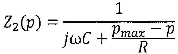
Aufgrund der Induktionsspannung Uind fließt in den Endverbindungen 19a und 19b ein Induktionsstrom Iind, dessen Zusammenhang mit den Spannungen in den Endverbindungen 19a und 19b durch die folgenden Gleichungen beschrieben ist: ![]()
![]()
![]()
![]()
![]()
![]()
Für den Induktionsstrom Iind folgt ferner ![]()
![]()
![]()
![]()
![]()
![]()
Dabei ist die durch das Sendeelement 20 in das Empfangsmodul 12 induzierte Induktionsspannung Uind unabhängig von der Position p und kann daher in gewisser Weise als eine konstante Bezugsgröße betrachtet werden. Dagegen sind sowohl die Impedanzen Z1 und Z2 im ersten Endabschnitt 19a und im zweiten Endabschnitt 19b von der Position p des Sendeelements entlang der Längserstreckung x des Empfangsmoduls abhängig. Ferner sind die daran abfallenden Spannungen U1 bzw. U2 hinsichtlich ihrer Amplitude bzw. ihres Betrages und ihrer Phasenlage ϕ 1 bzw. ϕ 2 von der Position p des Sendelements abhängig.The induced by the transmitting
Wie bereits eingangs dargelegt wurde, haben die Erfinder erkannt, dass sich in Abhängigkeit der Phasenlage ϕ 1 und/oder ϕ 2 die Position p des Sendelements entlang der Längserstreckung x des Empfangsmoduls besonders effizient bestimmen lässt. Die von der Position abhängige Phasenlage ϕ 1(p) der Spannung U1 wird im Folgenden aus den bekannten Größen berechnet, um eine Positionsbestimmung des Sendeelements 20 zu erlauben. Für die Spannung U1 gilt: 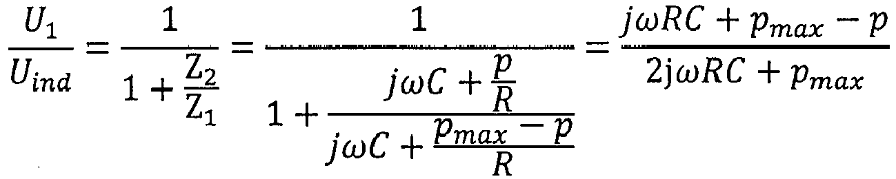
![]()

![]()
Die Phasenlage ϕ 1(p) bestimmt sich gemäß der Gleichung ![]()
![]()
Entsprechend ergibt sich für die Phasenlage ϕ 1(p) ![]()
![]()
![]()
![]()
Für eine besonders bevorzugte Ausführungsform, welche ein Empfangsmodul aufweist, das in der Richtung der Längserstreckung x achsensymmetrisch bezüglich einer Achse senkrecht zur Längserstreckung x durch den Mittelpunkt des Empfangsmoduls ist, kann die mathematische Darstellung der ersten Phasenlage ϕ 1(p) wie folgt dargestellt werden: 
![]()
![]()
In entsprechender Weise gilt für die Spannung U2, welche in der zweiten Endverbindung 19b abfällt: 


Die von der Position p des Sendelements 20 abhängige zweite Phasenlage ϕ 2(p) ergibt sich demnach zu ![]()
![]()

![]()
![]()
Dies zeigt, dass die erste Phasenlage ϕ 1(p) und/oder die zweite Phasenlage ϕ 2(p) abhängig von der Position p des Sendelements entlang der Längserstreckung x des Empfangsmoduls sind. Daher kann in Abhängigkeit der ersten Phasenlage ϕ 1 (p) und/oder der zweiten Phasenlage ϕ 2(p) die Position p des Sendeelements bestimmt werden.This shows that the first phase position φ 1 ( p ) and / or the second phase position φ 2 ( p ) are dependent on the position p of the transmitting element along the longitudinal extent x of the receiving module. Therefore, depending on the first phase position φ 1 (p) and / or the second phase position φ 2 ( p ), the position p of the transmitting element can be determined.
Insbesondere ist eine derartige Anpassung besonders effizient, wenn die Flächenausdehnung der zeitlichen Änderung der magnetischen Flussänderung d Φ/dt in der durch die erste Längsleiterkomponente 14a und die zweite Längsleiterkomponente 14b aufgespannten Ebene in etwa den Abmessungen eines Empfangsmodulsegments 16a entspricht. Bei unterschiedlich groß ausgebildeten Empfangsmodulsegmenten 16a können die für eine derartige Anpassung herangezogenen Abmessungen beispielsweise durch Mittelung über sämtliche Empfangsmodulsegmente 12a ermittelt werden.In particular, such an adaptation is particularly efficient if the surface extent of the temporal change of the magnetic flux change d Φ / dt in the plane spanned by the first
Des Weiteren umfasst die Sendeelementspule 28 in der gezeigten Ausführungsform einen Spulenkern 30. Dieser kann ferromagnetische Stoffe (wie beispielsweise Fe, Ni und/oder Co) und/oder ferromagnetische Legierungen (wie beispielsweise AlNiCo und/oder SmCo und/oder Permalloy) aufweisen. Zusätzlich oder alternativ kann der Spulenkern 30 ferrimagnetische, insbesondere elektrisch schlecht-leitende oder nichtleitende, Substanzen wie etwa Ferrite (beispielsweise Hämatit Fe2O3 oder Magnetit Fe3O4) aufweisen. Ferrite haben dabei den Vorteil, dass durch die schlechten oder nicht vorhandenen Leitfähigkeiten verlustbringende Wirbelströme im Spulenkern 30 unterdrückt werden können. Der Spulenkern 30 ist dabei vorzugsweise an die Innenmaße der Sendeelementspule 28 angepasst und füllt diese aus. Hat beispielsweise die Sendeelementspule 28 einen runden Querschnitt mit einem Innendurchmesser von 5 mm und eine Länge von 50 mm, so ist es besonders effizient einen Spulenkern 30 mit ebenfalls einem runden Querschnitt von 5 mm Durchmesser und 50 mm Länge zu verwenden, damit dieser das durch die Wicklungen der Sendeelementspule 28 aufgespannte Innenvolumen der Spule 28 so gut wie möglich ausfüllt. Allerdings kann der Spulenkern 30 auch eine größere Länge als die Sendeelementspule 28 aufweisen und über diese hinausragen. Besonders effizient ist es jedoch, wenn der Spulenkern 30 bündig mit derjenigen Öffnung der Sendeelementspule 28 abschließt, welche dem Empfangsmodul 12 zugewandt ist. Dies hat den Vorteil, dass der Abstand zwischen Sendeelementspule 28 und Spulenkern 30 bzw. Sendeelement 20 zum Empfangsmodul 12 sehr klein gewählt werden kann, beispielsweise im Bereich von 1 mm bis 5 mm. Durch einen derart geringen Abstand zwischen Sendeelement 20 und Empfangsmodul 12 kann die zeitliche Änderung des magnetischen Flusses Φ im Empfangsmodul 12, die durch Induktion aufgrund eines Sendeelementstroms Ise verursacht wird, maximiert werden.Further, in the embodiment shown, the
Jedoch können andere bevorzugte Ausführungsformen der erfindungsgemäßen Vorrichtung zur Positionsbestimmung 10 auch andere Formen und/oder Größen des Spulenkerns 30 und/oder Anordnungen der Sendeelementspule 28 um den Spulenkern 30 aufweisen. Beispielsweise können weitere bevorzugte Ausführungsformen einen im Wesentlichen U-förmigen oder Hufeisen-förmigen Spulenkern 30 aufweisen, welcher teilweise oder vollständig von der Sendeelementspule 28 umwickelt sein kann. Beispielsweise kann die Induktion von elektrischer Leistung vom Sendeelement 20 in das Empfangsmodul 12 besonders effizient erfolgen, wenn ein Ende des U-förmigen bzw. Hufeisen-förmigen Spulenkerns 30 direkt über dem Empfangsmodul 12 angeordnet ist und das andere Ende des Spulenkerns 30 direkt unterhalb des Empfangsmoduls 12 angeordnet ist. In anderen Worten kann die Induktion besonders effizient erfolgen, wenn das Empfangsmodul 12 durch das "offene" Ende des U-förmigen bzw. Hufeisen-förmigen Spulenkerns 30 hindurch verläuft. Die Sendeelementspule 28 kann dabei beispielsweise entlang des gesamten Spulenkerns 30 von einem Ende des Spulenkerns 30 zu dem anderen Ende des Spulenkerns 30 gewickelt sein, oder auch nur entlang eines Teils des Spulenkerns 30. Auf diese Weise kann beispielsweise eine besonders effiziente Führung bzw. Bündelung von magnetischen Feldlinien durch das Empfangsmodul 12 hindurch erreicht werden. In einer anderen bevorzugten Ausführungsform wird als Spulenkern ein E-Kern (Kern in "E"-Form) verwendet, wobei insbesondere der mittlere Steg zur Einkopplung des magnetischen Wechselfeldes in einen Bereich zwischen den Längsleiterkomponenten 14a, 14b und die äußeren Stege des E-Kerns zur Rückführung des magnetischen Feldes jeweils außerhalb der ersten bzw. zweiten Längsleiterkomponente dient. Mit dieser Anordnung kann besonders effizient das Auftreten von magnetischen Streufeldern zwischen den Längsleiterkomponenten aber abseits von der Position des Sendeelements verringert werden.However, other preferred embodiments of the
Durch das Fließen eines sich zeitlich ändernden Sendeelementstroms Ise im Schwingkreis 22 des Sendeelements 20 entsteht in der Sendeelementspule 28 ein sich zeitlich änderndes Magnetfeld. Der Spulenkern 30 verstärkt die Entstehung dieses Magnetfeldes. Wird der Schwingkreis 22 nicht durch eine externe Spannungsquelle getrieben (beispielsweise durch ein Wechselspannungsnetzteil) so oszilliert eine ggf. vorhandene Spannung am Kondensator 26 und der ggf. vorhandene Sendeelementstrom Ise durch die Spule 28 mit der Resonanzfrequenz des Schwingkreises. Insbesondere oszillieren die Spannung und der Strom dann, wenn dem Schwingkreis zuvor elektrische Leistung hinzugefügt wurde, d.h. wenn der Schwingkreis 22 zuvor mit Wechselspannung bzw. mit Wechselstrom getrieben wurde oder der Kondensator mit Gleichspannung aufgeladen wurde und die Schwingungen noch nicht abgeklungen sind. Die Resonanzfrequenz, mit der die Spannung und der Sendeelementstrom Ise nach Beendigung der Leistungsversorgung im Schwingkreis 22 oszilliert, ist in der gezeigten bevorzugten Ausführungsform hauptsächlich durch die Kapazität des Kondensators 26 und die Induktivität der Sendeelementspule 28 bestimmt. Anstelle eines LC-Schwingkreises oder zusätzlich kann im Sendelement auch ein anderer Oszillator, z.B. ein Quarzoszillator, verwendet werden.By flowing a time-varying transmission element current I se in the
Ist das Sendelement 20 über dem Empfangsmodul 12 angeordnet, so verursacht der durch die Sendeelementspule 28 oszillierende Sendeelementstrom Ise im Empfangsmodul 12 lokal eine zeitliche Änderung des magnetischen Flusses Φ, welche der zeitlichen Änderung des Sendeelementstrom Ise folgt. Entsprechend wird im Empfangsmodul 12 auch ein Induktionsstrom Iind angeregt, welcher ebenfalls der zeitlichen Änderung des Sendeelementstrom Ise folgt. Wie bereits oben beschrieben verursacht der Induktionsstrom Iind das Auftreten von Spannungssignalen am ersten Endabschnitt 18a und am zweiten Endabschnitt 18b des Empfangsmoduls 12, welche jeweils den Spannungswert U1 bzw. U2 aufweisen. Auch die Spannungswerte U1 und U2 folgen dabei der zeitlichen Änderung des Sendeelementstrom Ise . Die Spannungswerte U1 und U2 an den Endabschnitten 18a und 18b können dabei eine unterschiedliche Phasenlage ϕ 1 bzw. ϕ 2 aufweisen, welche maßgeblich durch den jeweiligen Blindwiderstand der Endverbindungen 19a bzw. 19b, insbesondere durch einen darin ausgebildeten Kondensator und/oder eine darin ausgebildete Spule, hervorgerufen werden.Is the
Ferner weist die in
Für eine besonders vorteilhafte und effiziente Leistungsversorgung des Sendelements 20 durch den Leistungsversorgungsstrom ILV wird daher eine Phasenregelschleife (PLL = phase -locked loop) verwendet (nicht gezeigt), welche die Oszillationsfrequenz des Leistungsversorgungsstrom ILV derart bestimmt, dass diese eine möglichst geringe Abweichung von der Resonanzfrequenz des Schwingkreises 22 aufweist. Dies kann beispielsweise dadurch geschehen, dass zunächst der Schwingkreis durch einen Leistungsversorgungsstrom ILV beispielsweise mit einer nahe der Resonanzfrequenz vermuteten bzw. liegenden Oszillationsfrequenz oder einem kurzen Anregungspuls angeregt wird, und daraufhin der nach ggf. erfolgreicher Anregung des Schwingkreises 22 wiederum vom Schwingkreis 22 im Leistungsversorgungsleiter 32 induzierte Strom detektiert wird. Da der Schwingkreis 22 nach Beendigung der Leistungsversorgung durch die Leistungsversorgungseinrichtung stets mit seiner eigenen Resonanzfrequenz oszilliert, kann aus dem vom Schwingkreis 22 im Leistungsversorgungsleiter 32 induzierten Strom die Resonanzfrequenz bestimmt werden. Mit anderen Worten wird der Schwingkreis zunächst mit einem Anregungssignal angeregt, das die Resonanzfrequenz des Schwingkreises enthält oder nahe der Resonanzfrequenz des Schwingkreises liegt, um anschließend aus der "Antwort" des Schwingkreises 22 dessen Resonanzfrequenz zu bestimmen. Sollte beim ersten Versuch keine ausreichende Leistungsversorgung des Schwingkreises 22 stattfinden, kann der Vorgang mit anderen Oszillationsfrequenzen des Anregungssignals wiederholt werden.For a particularly advantageous and efficient power supply of the transmitting
Eine derartige Leistungsversorgung des Schwingkreises 22 mittels eines Leistungsversorgungsleiters 32 bietet den Vorteil, dass das Sendeelement 20 zur Leistungsversorgung nicht verkabelt werden muss und dass keine Batterien oder sonstige erneuerungsbedürftige Spannungsquellen im beweglichen Sendeelement 20 vorgesehen werden müssen. Dies erlaubt es, die Komplexität und die Größe des Sendeelements 20 zu reduzieren und störende Einflüsse auf dessen Bewegbarkeit durch eine etwaige Verkabelung zu vermeiden.Such a power supply of the
Im Unterschied zur vorherigen Ausführungsform weist in der zweiten bevorzugten Ausführungsform der Leistungsversorgungsleiter 32 mehrere Windungen auf. Beispielsweise kann der Leistungsversorgungsleiter 32 drei Windungen um das Empfangsmodul 12 herum aufweisen. Dies hat den Effekt, dass die durch den Leistungsversorgungsstrom ILV verursachte Änderung des magnetischen Flusses innerhalb der Windungen des Leistungsversorgungsleiters 32 und die daraus resultierende Induktion des Sendeelementstrom Ise in etwa um die Anzahl der Windungen vervielfacht wird. Somit kann ein geringerer Leistungsversorgungsstrom ILV ausreichend sein, um eine effiziente Leistungsversorgung des Sendeelements 20 zu bewirken.Unlike the previous embodiment, in the second preferred embodiment, the
Beispielsweise kann der Leistungsversorgungsstrom ILV einen Wert von 20 mA (Milliampere) aufweisen. Wenn der Leistungsversorgungsleiter 32 drei Windungen aufweist, verursacht dies in etwa eine Induktion eines Sendeelementstroms Ise , für den bei nur einer Leiterschleife im Leistungsversorgungsleiter 32 ein Leistungsversorgungsstrom ILV von 60 mA nötig wäre. Auch andere Vervielfachungswerte sind durch eine entsprechend andere Anzahl von Windungen möglich.For example, the power supply current I LV may have a value of 20 mA (milliamperes). When the
In der dritten bevorzugten Ausführungsform umfasst der Leistungsversorgungsleiter 32 die erste Längsleiterkomponente 14a und die zweite Längsleiterkomponente 14b des Empfangsmoduls. D.h. dass die beiden Längsleiterkomponenten 14a und 14b einerseits als Leistungsversorgungsleiter 32 dienen, um das Sendelement 20 induktiv mit elektrischer Leistung zu versorgen und andererseits als Teil des Empfangsmoduls 12 dienen, um den vom Sendeelement 20 induzierten Induktionsstrom Iind zu leiten.In the third preferred embodiment, the
Um beide Funktionen der Längsleiterkomponenten 14a und 14b, nämlich einerseits als Leistungsversorgungsleiter 32 und andererseits als Teil des Empfangsmoduls 12, störungsfrei ausführen zu können, sind in der beschriebenen Ausführungsform mehrere Schaltkontakte 34 vorgesehen. Mittels dieser Schaltkontakte 34 können die Längsleiterkomponenten 14a und 14b einerseits von der Leistungsversorgungseinrichtung (nicht gezeigt), insbesondere von einer Spannungsversorgung der Leistungsversorgungseinrichtung, getrennt werden und andererseits kann ein am anderen Endabschnitt 18b ausgebildeter elektrischer Kurzschluss der beiden Längsleiterkomponenten 14a und 14b unterbrochen werden. Der genannte elektrische Kurzschluss ist zur Verwendung als Leistungsversorgungsleiter 32 erforderlich, um mittels der Leistungsversorgungseinrichtung das Sendeelement 20 mit Leistung zu versorgen, allerdings wäre der elektrische Kurzschluss während der Messung der Spannungswerte U1 und U2 bzw. während dem Ermitteln der Phasenlage ϕ 1 und/oder ϕ 1 hinderlich.In order to perform both functions of the
Aus diesem Grund müssen die Schaltkontakte 34 während Leistungsversorgungs-Phasen bzw. in Leistungszyklen LZ, in denen das Sendeelement 20 mit elektrischer Leistung versorgt wird, geschlossen und somit elektrisch leitend sein. Entsprechend müssen die Schaltkontakte 34 während Mess-Phasen bzw. in Messzyklen MZ, in denen Messung der Spannungswerte U1 und U2 bzw. der Phasenlage ϕ 1 und/oder ϕ 2 im Empfangsmodul erfolgt, geöffnet und somit nicht-leitend sein.For this reason, the
Die Verläufe der Phasenlage ϕ 1 und ϕ2 sind für zwei verschiedene Vorrichtungen 10 aufgetragen, welche in den oben dargelegten Parametern identisch sind, die sich jedoch in den Kondensatoren 17 in den jeweiligen Endverbindungen 19a und 19b unterscheiden. In der ersten Konfiguration weist die Vorrichtung 10 an den Endverbindungen 19a und 19b jeweils einen Kondensator 17 mit einer Kapazität von 68 nF auf, weshalb somit die Endverbindungen 19a und 19b einen Blindwiderstandswert gemäß der Formel ![]()
![]()
![]()
![]()
Für beide Konfigurationen ist in
Die verschiedenen Kapazitäten, welche die beiden Konfigurationen der Vorrichtung 10 unterscheiden, bewirken dabei eine unterschiedliche Steigung der Änderung der Phasenlagen ϕ 1 und ϕ 2. Die etwas größere Kapazität von 150 nF der Kondensatoren 17 hat dabei eine geringere Steigung der Änderung der Phasenlagen ϕ 1 und ϕ 2 mit sich ändernder Position p des Sendeelements 20 zur Folge, als die etwas kleine Kapazität von 68 nF der Kondensatoren 17. In anderen Worten weist die Vorrichtung in der Konfiguration mit jeweils einem Kondensator mit einer Kapazität 68 nF in den Endabschnitten 19a und 19b eine größere Empfindlichkeit auf als die ansonsten gleichartige Vorrichtung, welche im Unterschied zur ersten Konfiguration jeweils einen Kondensator 17 mit einer Kapazität von 150 nF in der ersten und der zweiten Endverbindung 19a und 19b aufweist. Andererseits ist erkennbar, dass im Beispiel mit der höheren Kapazität von 150 nF die Linearität des Zusammenhangs zwischen der Position und der Phasenlage gegenüber dem Beispiel mit niedrigerer Kapazität verbessert wird. Mittels einer geeigneten Wahl des Blindwiderstandes der jeweiligen Endverbindungen 19a und 19b kann somit auf effiziente Weise ein gewünschtes Maß an Sensitivität und Linearität eingestellt und die Vorrichtung zur Positionsbestimmung auf die Erfordernisse und gewünschten Eigenschaften hin optimiert werden.The different capacitances, which distinguish the two configurations of the
Die Abhängigkeit der Steigung des Verlaufs der Phasenlagen ϕ 1 und ϕ 2 kann insbesondere dadurch verstanden werden, dass der Term (ωRC)2 im Nenner der Formeln für die ersten Phasenlage ϕ 1 und die zweite Phasenlage ϕ 2 mit zunehmender Kapazität C quadratisch wächst, während die verbleibenden Terme im Nenner, welche von p abhängen, nicht mit zunehmender Kapazität C wachsen. Dies führt dazu, dass mit zunehmender Kapazität C der (ωRC)2 den Nenner bzw. die Phasenlage ϕ 1 bzw. ϕ 2 dominiert und/oder die weiteren Terme, welche von p abhängigen, zunehmend vernachlässigbar werden.The dependence of the gradient of the course of the phase positions φ 1 and φ 2 can in particular be understood by the term ( ωRC ) 2 in the denominator of the formulas for the first phase position φ 1 and the second phase position φ 2 increasing capacity C increases quadratically, while the remaining terms in the denominator, which depend on p, do not grow with increasing capacity C. As a result, with increasing capacitance C, the ( ωRC ) 2 dominates the denominator or the phase position φ 1 or φ 2 and / or the further terms which depend on p become increasingly negligible.
Unter den Bedingungen, welche eine derartige Näherung erlauben, d.h. unter welchen die von p abhängigen Terme im Nenner der Funktion für die Phasenlagen ϕ 1 und ϕ 2 dominiert werden, können die Phasenlagen ϕ 1 und ϕ 2 durch die folgenden Formeln ausgedrückt werden: ![]()
![]()
![]()
![]()
Aufgrund des gemäß der Näherung dominierend Terms ωRC, wird zudem das Argument der Arkustangens-Funktion klein, sodass die Arkustangens-Funktion lokal durch eine Taylorreihe unter Berücksichtigung der ersten Näherungsordnung durch arctan(x) ≈ x genähert werden kann, womit sich die obigen Formeln wie folgt vereinfachen: ![]()
![]()
![]()
![]()
Dies entspricht einer linearen Funktion, welche sich wie in
Die Phasenverschiebung entspricht dabei der Differenz der beiden Phasenlagen ϕ 1 und ϕ 2: ![]()
![]()
Wie in
Aus diesem Grund kann es besonders vorteilhaft sein, die Positionsbestimmung in Abhängigkeit der Phasenverschiebung Δϕ durchzuführen, da unter Umständen eine größere Messgenauigkeit erzielt werden kann, als bei Verwendung der einzelnen Phasenlagen ϕ 1 und/oder ϕ 2 ohne die Bildung einer Differenz.For this reason, it may be particularly advantageous to carry out the position determination as a function of the phase shift Δφ , since under certain circumstances a greater accuracy of measurement can be achieved than when using the individual phase positions φ 1 and / or φ 2 without the formation of a difference.
Eine vertikale Hilfslinie VH, welche sich über alle drei Figuren
Auch wenn die Erfindung in einigen Ausführungsformen vor allem anhand der Implementierung mit Wirkwiderstandswerten in den Querverbindungen und Blindwiderstandswerten in den Endverbindungen beschrieben wurde, kann sie in analoger Weise auch mit den vertauschten Rollen von Wirk- und Blindwiderstandswerten implementiert und genutzt werden. Somit sind insbesondere die Ausführungen zu den Bauteilen und/oder Zahlenwerten des ersten und/oder zweiten elektrischen Blindwiderstandswerts in der jeweiligen Endverbindung der ersten Implementierung auch auf die vorbestimmten elektrischen Blindwiderstandswerte in der Vielzahl von Querverbindungen in der zweiten Implementierung übertragbar. Entsprechend sind vorzugsweise die Ausführungen zu den Bauteilen und/oder Zahlenwerten der vorbestimmten elektrischen Wirkwiderstandswerte in den Querverbindungen der ersten Implementierung auch auf den ersten und/oder zweiten elektrischen Wirkwiderstandswert in der jeweiligen Endverbindung der zweiten Implementierung übertragbar.Although the invention has been described in some embodiments, especially on the basis of the implementation with resistance values in the interconnections and reactance values in the end connections, it can also be used in an analogous manner with the reversed roles of active and Reactance values are implemented and used. Thus, in particular, the implementations of the components and / or numerical values of the first and / or second electrical reactance values in the respective end connection of the first implementation are also transferable to the predetermined electrical reactance values in the plurality of interconnections in the second implementation. Accordingly, the explanations concerning the components and / or numerical values of the predetermined electrical resistance values in the cross connections of the first implementation are preferably also applicable to the first and / or second electrical resistance value in the respective end connection of the second implementation.
- 1010
- Vorrichtung zur PositionsbestimmungDevice for determining position
- 1212
- Empfangsmodulreceiver module
- 12a12a
- EmpfangsmodulsegmentReceiver module segment
- 14a14a
- erste Längsleiterkomponentefirst longitudinal conductor component
- 14b14b
- zweite Längsleiterkomponentesecond longitudinal conductor component
- 1616
- Querverbindungcross connection
- 16a16a
- WirkwiderstandselementResistive element
- 1717
- Kondensatorcapacitor
- 18a18a
- erster Endabschnittfirst end section
- 18b18b
- zweiter Endabschnittsecond end section
- 19a19a
- erste Endverbindungfirst end connection
- 19b19b
- zweite Endverbindungsecond end connection
- 2020
- Sendeelementtransmitting element
- 2222
- Schwingkreisresonant circuit
- 2424
- SchwingkreiswiderstandResonant circuit resistance
- 2626
- SendeelementkondensatorTransmitting element capacitor
- 2828
- SendeelementspuleTransmitting element coil
- 3030
- SpulenkernPlunger
- 3232
- LeistungsversorgungsleiterPower supply conductor
- 3434
- Schaltkontaktswitching contact
- xx
- Längserstreckung (des Empfangsmoduls)Longitudinal extension (of the receiving module)
- xi x i
- Position einer Querverbindung entlang der Längserstreckung x Position of a transverse connection along the longitudinal extension x
- pp
- Position des Sendeelements entlang der LängserstreckungPosition of the transmitting element along the longitudinal extent
- pmax p max
- Position der letzten QuerverbindungPosition of the last cross connection
- ΦΦ
- magnetischer Flussmagnetic river
- da/dt da / dt
- zeitliche Änderung des magnetischen Flussestemporal change of the magnetic flux
- U1 U 1
- erster Spannungswertfirst voltage value
- U2 U 2
- zweiter Spannungswertsecond voltage value
- Iind I ind
- Induktionsstrom (im Empfangsmodul)Induction current (in the receiving module)
- Ise I se
- SendeelementstromTransmitting element current
- ILV I LV
- LeistungsversorgungsstromPower supply current
- LZLZ
- Leistungszykluspower cycle
- MZMZ
- Messzyklusmeasuring cycle
- VHVH
- vertikale Hilfslinievertical guide
Claims (15)
wobei die vorbestimmten Wirkwiderstandswerte (R) der Vielzahl von elektrisch leitenden Querverbindungen (16) bzw. der erste Wirkwiderstandswert (R1 ) und/oder der zweite Wirkwiderstandswert (R2 ) jeweils im Bereich von zumindest etwa 0,1 kΩ, vorzugsweise in einem Bereich von zumindest etwa 0,5 kΩ, besonders bevorzugt in einem Bereich von zumindest etwa 1 kΩ und/oder in einem Bereich von nicht mehr als etwa 10 MΩ, besonders bevorzugt in einem Bereich von nicht mehr als etwa 1 MΩ, weiter bevorzugt in einem Bereich von nicht mehr als etwa 100 kΩ, am meisten bevorzugt in einem Bereich von nicht mehr als etwa 10 kΩ liegen bzw. liegt.Device according to one of the preceding claims, wherein the first reactance value ( X 1 ) and / or the second reactance value ( X 2 ) or the predetermined reactance values (X) of the plurality of electrically conductive cross-connections, in particular at least one inducible by the transmitting element periodic electric current flow ( I ind ) or at least one inducible by the transmitting element periodic electrical voltage ( U ind ) at least 1 Ω and / or at most 10 kΩ, preferably at least 10 Ω and / or at most 1 kΩ, more preferably at least 20 Ω and / or at most 0 , 5kΩ, even more preferably at least 30Ω and / or at most 0.2kΩ, most preferably at least 50Ω and / or at most 0.1kΩ; and or
wherein the predetermined effective resistance values (R) of the plurality of electrically conductive cross-connections (16) and the first resistive value (R 1) and / or the second effective resistance value ( R 2 ) is in each case in the range of at least about 0.1 kΩ, preferably in a range of at least about 0.5 kΩ, particularly preferably in a range of at least about 1 kΩ and / or in a range of not more than is about 10 MΩ, more preferably in a range of not more than about 1 MΩ, more preferably in a range of not more than about 100 kΩ, most preferably in a range of not more than about 10 kΩ.
wobei die Vielzahl von Querverbindungen (16) äquidistant entlang der Längserstreckung (x) des Empfangsmoduls (12) angeordnet sind, und/oder
wobei jede Querverbindung (16) vorzugsweise einen identischen Wirkwiderstandswert (R) bzw. Blindwiderstandswert (X) aufweist.Device according to one of the preceding claims, wherein the receiving module (12) a number of electrically conductive cross-connections (16) in the range of at least about 5, preferably in a range of at least about 20, more preferably in a range of at least about 50 and / or in a range of not more than about 1000, more preferably in a range of not more than about 500, more preferably in a range of not more than about 200; and or
wherein the plurality of cross connections (16) are arranged equidistantly along the longitudinal extension (x) of the receiving module (12), and / or
wherein each cross-connection (16) preferably has an identical resistance value (R) or resistance value (X).
wobei in einem Messzyklus (MZ) das Sendeelement (20) induktiv an das Empfangsmodul (12) koppelt und einen elektrischen Stromfluss und/oder eine elektrische Spannung in dem Empfangsmodul (20) induziert,
wobei der Leistungszyklus (LZ) und der Messzyklus (MZ) zeitlich zumindest nicht vollständig überlappen.Method according to one of claims 11 to 14, wherein during a power cycle, a power supply device inductively couples to the transmitting element (20) and induces an electric current flow and / or an electrical voltage in the transmitting element (20), and
wherein in a measuring cycle (MZ) the transmitting element (20) inductively couples to the receiving module (12) and induces an electric current flow and / or an electrical voltage in the receiving module (20),
wherein the power cycle (LZ) and the measurement cycle (MZ) at least do not completely overlap in time.
Priority Applications (1)
| Application Number | Priority Date | Filing Date | Title |
|---|---|---|---|
| EP15002662.3A EP3141869A1 (en) | 2015-09-11 | 2015-09-11 | Phase-based position detection using termination blind resistors |
Applications Claiming Priority (1)
| Application Number | Priority Date | Filing Date | Title |
|---|---|---|---|
| EP15002662.3A EP3141869A1 (en) | 2015-09-11 | 2015-09-11 | Phase-based position detection using termination blind resistors |
Publications (1)
| Publication Number | Publication Date |
|---|---|
| EP3141869A1 true EP3141869A1 (en) | 2017-03-15 |
Family
ID=54145522
Family Applications (1)
| Application Number | Title | Priority Date | Filing Date |
|---|---|---|---|
| EP15002662.3A Withdrawn EP3141869A1 (en) | 2015-09-11 | 2015-09-11 | Phase-based position detection using termination blind resistors |
Country Status (1)
| Country | Link |
|---|---|
| EP (1) | EP3141869A1 (en) |
Citations (2)
| Publication number | Priority date | Publication date | Assignee | Title |
|---|---|---|---|---|
| US4007454A (en) | 1975-09-12 | 1977-02-08 | Charles J. Cain | Apparatus for remotely determining the angular orientation, speed, and/or direction of rotation of objects |
| WO2007107353A1 (en) * | 2006-03-21 | 2007-09-27 | Hochschule Mannheim Hochschule Für Technik Und Gestaltung | Sensor for measuring distance using the phase shift of the magnetic field in an rc delay chain |
-
2015
- 2015-09-11 EP EP15002662.3A patent/EP3141869A1/en not_active Withdrawn
Patent Citations (3)
| Publication number | Priority date | Publication date | Assignee | Title |
|---|---|---|---|---|
| US4007454A (en) | 1975-09-12 | 1977-02-08 | Charles J. Cain | Apparatus for remotely determining the angular orientation, speed, and/or direction of rotation of objects |
| WO2007107353A1 (en) * | 2006-03-21 | 2007-09-27 | Hochschule Mannheim Hochschule Für Technik Und Gestaltung | Sensor for measuring distance using the phase shift of the magnetic field in an rc delay chain |
| DE102006012952A1 (en) | 2006-03-21 | 2008-01-03 | Fachhochschule Mannheim Hochschule für Technik und Gestaltung | Device and method for position determination |
Similar Documents
| Publication | Publication Date | Title |
|---|---|---|
| EP2895889B1 (en) | Metal foreign body-identification system for inductive energy transmission systems | |
| DE19631438C2 (en) | Eddy current sensor | |
| EP3335011B1 (en) | Device for measuring a variable | |
| EP3124314B1 (en) | Foreign object detection, in particular for wireless charging systems | |
| DE102010007620B9 (en) | Proximity sensor | |
| DE3840532C2 (en) | ||
| DE602004010486T2 (en) | Inductive proximity sensor | |
| EP2389564A1 (en) | Method for the inductive generation of an electrical measuring signal and associated sensor device | |
| WO2016149723A1 (en) | Lock or window or door fitting | |
| EP3293499B1 (en) | Method of operating a magnetic-inductive flow meter and magnetic-inductive flow meter | |
| WO2011138063A2 (en) | Detection of a metal or magnetic object | |
| EP0447653B1 (en) | Inductive position sensor | |
| DE102004053551A1 (en) | Detector of mobile, or movable part, electrically and/or magnetically conductive, incorporates two electric circuits and control and/or regulating device, with specified components of both electric circuits | |
| EP3141869A1 (en) | Phase-based position detection using termination blind resistors | |
| EP3357742A1 (en) | Device for detecting objects, in particular for charging systems | |
| EP3824323B1 (en) | Detector for detecting electrically conductive material | |
| EP3327431B1 (en) | Inductive conductivity sensor and method for operating an inductive conductivity sensor | |
| EP3557188A1 (en) | Magnetized piston rod for measuring displacement | |
| EP3975211B1 (en) | Unification of resolver and inductive rotor supply in one magnetic circuit | |
| EP0805423A2 (en) | Device for checking te validity of coins, tokens or other flat metallic objects | |
| EP3015826B1 (en) | Sensor device, operating tool and method for operating the same | |
| WO2020125994A1 (en) | Method and apparatus for detecting electrically conductive foreign bodies during inductive energy transmission | |
| EP2184623A2 (en) | Sensor device for detecting an object and its movement in a measurement area of the sensor device | |
| DE102013100841A1 (en) | Transducer for determining thread tensile force on textile machine, has sensor element with coil, plunger coil with annular body that has immersion opening for sensor element |
Legal Events
| Date | Code | Title | Description |
|---|---|---|---|
| PUAI | Public reference made under article 153(3) epc to a published international application that has entered the european phase |
Free format text: ORIGINAL CODE: 0009012 |
|
| AK | Designated contracting states |
Kind code of ref document: A1 Designated state(s): AL AT BE BG CH CY CZ DE DK EE ES FI FR GB GR HR HU IE IS IT LI LT LU LV MC MK MT NL NO PL PT RO RS SE SI SK SM TR |
|
| AX | Request for extension of the european patent |
Extension state: BA ME |
|
| STAA | Information on the status of an ep patent application or granted ep patent |
Free format text: STATUS: THE APPLICATION IS DEEMED TO BE WITHDRAWN |
|
| 18D | Application deemed to be withdrawn |
Effective date: 20170916 |